Preparing a design for simulation 3 Chapter overview This chapter provides introductory information to help you enter circuit designs that simulate properly. If you want an overview, use the checklist on page 3-56 to guide you to specific topics. Topics include: • Checklist for simulation setup on page 3-56 • Using parts that you can simulate on page 3-60 • Using global parameters and expressions for values on page 3-67 • Defining power supplies on page 3-74 • Defining stimuli on page 3-75 • Things to watch for on page 3-79 Refer to your OrCAD Capture User’s Guide for general schematic entry information.
Transcript
Preparing a design for simulation
3
Chapter overviewThis chapter provides introductory information to help you enter circuit designs that simulate properly. If you want an overview, use the checklist on page 3-56 to guide you to specific topics.
Topics include:
• Checklist for simulation setup on page 3-56
• Using parts that you can simulate on page 3-60
• Using global parameters and expressions for values on page 3-67
• Defining power supplies on page 3-74
• Defining stimuli on page 3-75
• Things to watch for on page 3-79
Refer to your OrCAD Capture User’s Guide for general schematic entry information.
Pspug.book Page 55 Wednesday, November 11, 1998 1:14 PM
Chapter 3 Preparing a design for simulation
56
Checklist for simulation setupThis section describes what you need to do to set up your circuit for simulation.
1 Find the topic that is of interest in the first column of any of these tables.
2 Go to the referenced section. For those sections that provide overviews, you will find references to more detailed discussions.
Typical simulation setup steps
For more information on this step... See this... To find out this...
✔ Set component values and other properties.
Using parts that you can simulate on page 3-60
An overview of vendor, passive, breakout, and behavioral parts.
Using global parameters and expressions for values on page 3-67
How to define values using variable parameters, functional calls, and mathematical expressions.
✔ Define power supplies.
Defining power supplies on page 3-74
An overview of DC power for analog circuits..
✔ Define input waveforms.
Defining stimuli on page 3-75
An overview of DC, AC, and time-based stimulus parts.
✔ Set up one or more analyses.
Chapter 7, Setting up analyses and starting simulation
Procedures, general to all analysis types, to set up and start the simulation.
Chapter 8 through Chapter 12 (see the table of contents)
Detailed information about DC, AC, transient, parametric, temperature, Monte Carlo, and sensitivity/worst-case..
Pspug.book Page 56 Wednesday, November 11, 1998 1:14 PM
Checklist for simulation setup
57
Advanced design entry and simulation setup steps
For more information on this step... See this...
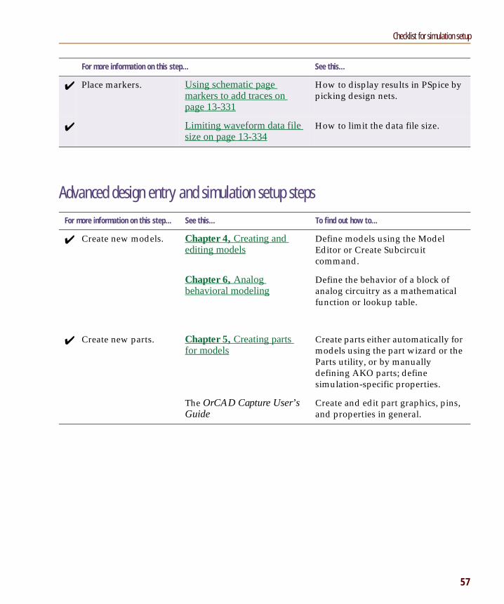
✔ Place markers. Using schematic page markers to add traces on page 13-331
How to display results in PSpice by picking design nets.
✔ Limiting waveform data file size on page 13-334
How to limit the data file size.
For more information on this step... See this... To find out how to...
✔ Create new models. Chapter 4, Creating and editing models
Define models using the Model Editor or Create Subcircuit command.
Chapter 6, Analog behavioral modeling
Define the behavior of a block of analog circuitry as a mathematical function or lookup table.
✔ Create new parts. Chapter 5, Creating parts for models
Create parts either automatically for models using the part wizard or the Parts utility, or by manually defining AKO parts; define simulation-specific properties.
The OrCAD Capture User’s Guide
Create and edit part graphics, pins, and properties in general.
Pspug.book Page 57 Wednesday, November 11, 1998 1:14 PM
Chapter 3 Preparing a design for simulation
58
When netlisting fails or the simulation does not startIf you have problems starting the simulation, there may be problems with the design or with system resources. If there are problems with the design, PSpice displays errors and warnings in the Simulation Output window. You can use the Simulation Output window to get more information quickly about the specific problem.
To get online information about an error or warning shown in the Simulation Output window
1 Select the error or warning message.
2 Press 1.
The following tables list the most commonly encountered problems and where to find out more about what to do.
Things to check in your designTable 5
Make sure that... To find out more, see this...
✔ The model libraries, stimulus files, and include files are configured.
Configuring model libraries on page 4-120
✔ The parts you are using have models. Unmodeled parts on page 3-79 and Defining part properties needed for simulation on page 5-139
✔ You are not using unmodeled pins. Unmodeled pins on page 3-82
✔ You have defined the grounds. Missing ground on page 3-83
✔ Every analog net has a DC path to ground. Missing DC path to ground on page 3-84
✔ The part template is correct. Defining part properties needed for simulation on page 5-139
✔ Hierarchical parts, if used, are properly defined.
The OrCAD Capture User’s Guide
✔ Ports that connect to the same net have the same name.
The OrCAD Capture User’s Guide
Pspug.book Page 58 Wednesday, November 11, 1998 1:14 PM
Checklist for simulation setup
59
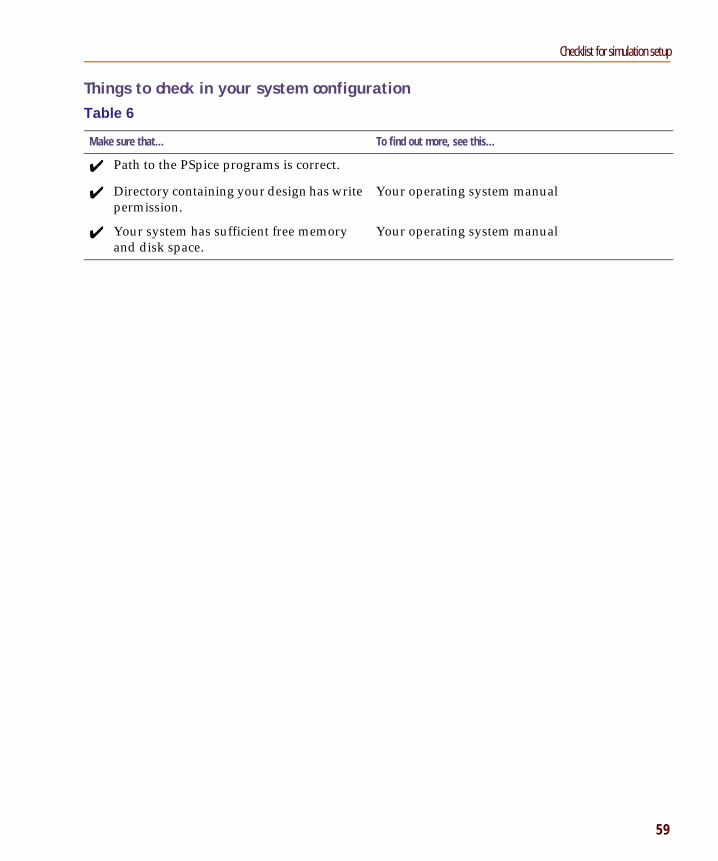
Things to check in your system configurationTable 6
Make sure that... To find out more, see this...
✔ Path to the PSpice programs is correct.
✔ Directory containing your design has write permission.
Your operating system manual
✔ Your system has sufficient free memory and disk space.
Your operating system manual
Pspug.book Page 59 Wednesday, November 11, 1998 1:14 PM
Chapter 3 Preparing a design for simulation
60
Using parts that you can simulateThe OrCAD part libraries supply numerous parts designed for simulation. These include:
• vendor-supplied parts
• passive parts
• breakout parts
• behavioral parts
At minimum, a part that you can simulate has these properties:
• A simulation model to describe the part’s electrical behavior; the model can be:
• explicitly defined in a model library,
• built into PSpice, or
• built into the part (for some kinds of analog behavioral parts).
• A part with modeled pins to form electrical connections in your design.
• A translation from design part to netlist statement so that PSpice can read it in.
Note Not all parts in the libraries are set up for simulation. For example, connectors are parts destined for board layout only and do not have these simulation properties.
The OrCAD part libraries also include special parts that you can use for simulation only. These include:
• stimulus parts to generate input signals to the circuit (see Defining stimuli on page 3-75)
• ground parts required by all analog circuits, which need reference to ground
• simulation control parts to do things like set bias values (see Appendix A, Setting initial state)
• output control parts to do things like generate tables and line-printer plots to the PSpice output file (see Chapter 14, Other output options)
Pspug.book Page 60 Wednesday, November 11, 1998 1:14 PM
Using parts that you can simulate
61
Vendor-supplied partsThe OrCAD libraries provide an extensive selection of manufacturers’ analog parts. Typically, the library name reflects the kind of parts contained in the library and the vendor that provided the models.
Example: MOTOR_RF.OLB and MOTOR_RF.LIB contain parts and models, respectively, for Motorola-made RF bipolar transistors.
Part naming conventionsThe part names in the OrCAD libraries usually reflect the manufacturers’ part names. If multiple vendors supply the same part, each part name includes a suffix that indicates the vendor that supplied the model.
Example: The OrCAD libraries include several models for the OP-27 opamp as shown by these entries in the online Library List.
For a listing of vendor-supplied parts contained in the OrCAD libraries, refer to the online Library List.
To find out more about each model library, read the comments in the .LIB file header.
Pspug.book Page 61 Wednesday, November 11, 1998 1:14 PM
Chapter 3 Preparing a design for simulation
62
Notice the following:
• There is a generic OP-27 part provided by OrCAD, the OP-27/AD from Analog Devices, Inc., and the OP-27/LT from Linear Technology Corporation.
• The Model column for all of these parts contains an asterisk. This indicates that this part is modeled and that you can simulate it.
Finding the part that you wantIf you are having trouble finding a part, you can search the libraries for parts with similar names by using either:
• the parts browser in Capture and restricting the parts list to those names that match a specified wildcard text string, or
• the online Library List and searching for the generic part name using capabilities of the Adobe Acrobat Reader.
To find parts using the parts browser
1 In Capture, from the Place menu, choose Part.
2 In the Part Name text box, type a text string with wildcards that approximates the part name that you want to find. Use this syntax:
<wildcard><part_name_fragment><wildcard>
where <wildcard> is one of the following:
The parts browser displays only the matching part names.
* to match zero or more characters
? to match exactly one character
Note This method finds any part contained in the current part libraries configuration, including parts for user-defined models.
If you want to find out more about a part supplied in the OrCAD libraries, such as manufacturer or whether you can simulate it, then search the online Library List (see page 3-63).
Pspug.book Page 62 Wednesday, November 11, 1998 1:14 PM
Using parts that you can simulate
63
To find parts using the online OrCAD Library List
1 In Windows Explorer, double-click LIBLIST.PDF, located in the directory where PSpice is installed.
Acrobat Reader starts and displays the OrCAD Library List.
2 From the Tools menu, choose Find.
3 In the Find What text box, type the generic part name.
4 Enter any other search criteria, and then click Find.
The Acrobat Reader displays the first page where it finds a match. Each page maps the generic part name to the parts (and corresponding vendor and part library name) in the OrCAD libraries.
5 If you want to repeat the search, from the Tools menu, choose Find Again.
Note If you are unsure of the device type, you can scan all of the device type lists using the Acrobat search capability. The first time you do this, you need to set up the across-list index. To find out more, refer to the online Adobe Acrobat manuals.
Note This method finds only parts that OrCAD supplies that have models.
If you want to include user-defined parts in the search, use the parts browser in Capture (see page 3-62).
or press C+F
Instead of the generic part name, you can enter other kinds of search information, such as device type or manufacturer.
press C+G
Pspug.book Page 63 Wednesday, November 11, 1998 1:14 PM
Chapter 3 Preparing a design for simulation
64
Passive partsThe OrCAD libraries supply several basic parts based on the passive device models built into PSpice. These are summarized in the following table.
Table 7 Passive parts
These parts are available... For this device type...
Which is this PSpice device letter...
CC_VAR
capacitor C
L inductor L
RR_VAR
resistor R
XFRM_LINEAR K_LINEAR
transformer K and L
T ideal transmission line T
TLOSSY Lossy transmission line T
TnCOUPLED*TnCOUPLEDX**KCOUPLEn**
* For these device types, the OrCAD libraries supply several parts. Refer to the online OrCAD PSpice A/D Reference Manual for the available parts.
coupled transmission line T and K
To find out more about how to use these parts and define their properties, look up the corresponding PSpice device letter in the Analog Devices chapter in the online OrCAD PSpice A/D Reference Manual, and then see the Capture Parts sections.
Pspug.book Page 64 Wednesday, November 11, 1998 1:14 PM
Using parts that you can simulate
65
Breakout partsThe OrCAD libraries supply passive and semiconductor parts with default model definitions that define a basic set of model parameters. This way, you can easily:
• assign device and lot tolerances to model parameters for Monte Carlo and sensitivity/worst-case analyses,
• define temperature coefficients, and
• define device-specific operating temperatures.
These are called breakout parts and are summarized in the following table.
Table 8 Breakout parts
Use this breakout part... For this device type...
Which is this PSpice device letter...
BBREAK GaAsFET B
CBREAK capacitor C
DBREAKx*
* For this device type, the OrCAD libraries supply several breakout parts. Refer to the online OrCAD PSpice Reference Manual for the available parts.
diode D
JBREAKx* JFET J
KBREAK inductor coupling K
LBREAK inductor L
MBREAKx* MOSFET M
QBREAKx* bipolar transistor Q
RBREAK resistor R
SBREAK voltage-controlled switch
S
TBREAK transmission line T
WBREAK current-controlled switch
W
XFRM_NONLINEAR transformer K and L
ZBREAKN IGBT Z
To find out more about models, see What are models? on page 4-87.
To find out more about Monte Carlo and sensitivity/worst-case analyses, see Chapter 12, Monte Carlo and sensitivity/worst-case analyses.
To find out more about setting temperature parameters, see the Analog Devices chapter in the online OrCAD PSpice A/D Reference Manual and find the device type that you are interested in.
To find out more about how to use these parts and define their properties, look up the corresponding PSpice device letter in the Analog Devices chapter of the online OrCAD PSpice A/D Reference Manual, and then look in the Capture Parts section.
Pspug.book Page 65 Wednesday, November 11, 1998 1:14 PM
Chapter 3 Preparing a design for simulation
66
Behavioral partsBehavioral parts allow you to define how a block of circuitry should work without having to define each discrete component.
Analog behavioral parts These parts use analog behavioral modeling (ABM) to define each part’s behavior as a mathematical expression or lookup table. The OrCAD libraries provide ABM parts that operate as math functions, limiters, Chebyshev filters, integrators, differentiators, and others that you can customize for specific expressions and lookup tables. You can also create your own ABM parts.
For more information, see Chapter 6, Analog behavioral modeling.
Pspug.book Page 66 Wednesday, November 11, 1998 1:14 PM
Using global parameters and expressions for values
67
Using global parameters and expressions for valuesIn addition to literal values, you can use global parameters and expressions to represent numeric values in your circuit design.
Global parametersA global parameter is like a programming variable that represents a numeric value by name.
Once you have defined a parameter (declared its name and given it a value), you can use it to represent circuit values anywhere in the design; this applies to any hierarchical level.
Some ways that you can use parameters are as follows:
• Apply the same value to multiple part instances.
• Set up an analysis that sweeps a variable through a range of values (for example, DC sweep or parametric analysis).
Declaring and using a global parameterTo use a global parameter in your design, you need to:
• define the parameter using a PARAM part, and
• use the parameter in place of a literal value somewhere in your design.
When multiple parts are set to the same value, global parameters provide a convenient way to change all of their values for “what-if” analyses.
Example: If two independent sources have a value defined by the parameter VSUPPLY, then you can change both sources to 10 volts by assigning the value once to VSUPPLY.
Pspug.book Page 67 Wednesday, November 11, 1998 1:14 PM
Chapter 3 Preparing a design for simulation
68
To declare a global parameter
1 Place a PARAM part in your design.
2 Double-click the PARAM part to display the Parts spreadsheet, then click New.
3 Declare up to three global parameters by doing the following for each global parameter:
a Click New.
b In the Property Name text box, enter NAMEn, then click OK.
This creates a new property for the PARAM part, NAMEn in the spreadsheet.
c Click in the cell below the NAMEn column and enter a default value for the parameter.
d While this cell is still selected, click Display.
e In the Display Format frame, select Name and Value, then click OK.
Note The system variables in Table 11 on page 3-73 have reserved parameter names. Do not use these parameter names when defining your own parameters.
4 Click Apply to update all the changes to the PARAM part.
5 Close the Parts spreadsheet.
To use the global parameter in your circuit
1 Find the numeric value that you want to replace: a component value, model parameter value, or other property value.
2 Replace the value with the name of the global parameter using the following syntax:
{ global_parameter_name }
The curly braces tell PSpice to evaluate the parameter and use its value.
Note For more information about using the Parts spreadsheet, see the OrCAD Capture User’s Guide.
Example: To declare the global parameter VSUPPLY that will set the value of an independent voltage source to 14 volts, place the PARAM part, and then create a new property named VSUPPLY with a value of 14v.
Example: To set the independent voltage source, VCC, to the value of the VSUPPLY parameter, set its DC property to {VSUPPLY}.
Pspug.book Page 68 Wednesday, November 11, 1998 1:14 PM
Using global parameters and expressions for values
69
ExpressionsAn expression is a mathematical relationship that you can use to define a numeric or boolean (TRUE/FALSE) value.
PSpice evaluates the expression to a single value every time:
• it reads in a new circuit, and
• a parameter value used within an expression changes during an analysis.
Specifying expressions
To use an expression in your circuit
1 Find the numeric or boolean value you want to replace: a component value, model parameter value, other property value, or logic in an IF function test (see page 3-72 for a description of the IF function).
2 Replace the value with an expression using the following syntax:
{ expression }
where expression can contain any of the following:
• standard operators listed in Table 9
• built-in functions listed in Table 10
• user-defined functions
• system variables listed in Table 11
• user-defined global parameters
• literal operands
The curly braces tell PSpice to evaluate the expression and use its value.
Example: A parameter that changes with each step of a DC sweep or parametric analysis.
Example: Suppose you have declared a parameter named FACTOR (with a value of 1.2) and want to scale a -10 V independent voltage source, VEE, by the value of FACTOR. To do this, set the DC property of VEE to:
{-10*FACTOR}
PSpice evaluates this expression to:
(-10 * 1.2) or -12 volts
For more information on user-defined functions, see the .FUNC command in the Commands chapter in the online OrCAD PSpice A/D Reference Manual.
For more information on user-defined parameters, see Using global parameters and expressions for values on page 3-67.
Pspug.book Page 69 Wednesday, November 11, 1998 1:14 PM
Chapter 3 Preparing a design for simulation
70
Table 9 Operators in expressions
This operator class...
Includes this operator... Which means...
arithmetic + addition or string concatenation
- subtraction
* multiplication
/ division
** exponentiation
logical*
* Logical and relational operators are used within the IF() function.
~ unary NOT
| boolean OR
^ boolean XOR
& boolean AND
relational* == equality test
!= non-equality test
> greater than test
>= greater than or equal to test
< less than test
<= less than or equal to test
Pspug.book Page 70 Wednesday, November 11, 1998 1:14 PM
Using global parameters and expressions for values
71
Table 10 Functions in arithmetic expressions
This function... Means this...
ABS(x) |x|
SQRT(x) x1/2
EXP(x) ex
LOG(x) ln(x) which is log base e
LOG10(x) log(x) which is log base 10
PWR(x,y) |x|y
PWRS(x,y) +|x|y (if x > 0)-|x|y (if x < 0)
SIN(x) sin(x) where x is in radians
ASIN(x) sin-1 (x) where the result is in radians
SINH(x) sinh(x) where x is in radians
COS(x) cos(x) where x is in radians
ACOS(x) cos-1 (x) where the result is in radians
COSH(x) cosh(x) where x is in radians
TAN(x) tan(x) where x is in radians
ATAN(x)ARCTAN(x)
tan-1 (x) where the result is in radians
ATAN2(y,x) tan-1 (y/x) where the result is in radians
TANH(x) tanh(x) where x is in radians
M(x) magnitude of x* which is the same as ABS(x)
P(x) phase of x* in degrees; returns 0.0 for real numbers
R(x) real part of x*
IMG(x) imaginary part of x*
which is applicable to AC analysis only
Pspug.book Page 71 Wednesday, November 11, 1998 1:14 PM
Chapter 3 Preparing a design for simulation
72
DDT(x) time derivative of x
which is applicable to transient analysis only
SDT(x) time integral of x which is applicable to transient analysis only
TABLE(x,x1,y1,...) y value as a function of x
where xn,yn point pairs are plotted and connected by straight lines
MIN(x,y) minimum of x and y
MAX(x,y) maximum of x and y
LIMIT(x,min,max) min if x < minmax if x > maxelse x
SGN(x) +1 if x > 00 if x = 0-1 if x < 0
STP(x) 1 if x > 00 otherwise
which is used to suppress a value until a given amount of time has passed
IF(t,x,y) x if t is truey otherwise
where t is a relational expression using the relational operators shown in Table 9
* M(x), P(x), R(x), and IMG(x) apply to Laplace expressions only.
Table 10 Functions in arithmetic expressions (continued)
This function... Means this...
Note In waveform analysis, this function is D(x).
Note In waveform analysis, this function is S(x).
Example: {v(1)*STP(TIME-10ns)} gives a value of 0.0 until 10 nsec has elapsed, then gives v(1).
Pspug.book Page 72 Wednesday, November 11, 1998 1:14 PM
Using global parameters and expressions for values
73
Table 11 System variables
This variable... Evaluates to this...
TEMP Temperature values resulting from a temperature, parametric temperature, or DC temperature sweep analysis. The default temperature, TNOM, is set in the Options dialog box (from the Simulation Settings dialog box, choose the Options tab). TNOM defaults to 27°C.Note TEMP can only be used in expressions pertaining to analog behavioral modelin.
TIME Time values resulting from a transient analysis. If no transient analysis is run, this variable is undefined.Note TIME can only be used in analog behavioral modeling expressions.
Note If a passive or semiconductor device has an independent temperature assignment, then TEMP does not represent that device’s temperature.
To find out more about customizing temperatures for passive or semiconductor devices, refer to the .MODEL command in the Commands chapter in the online OrCAD PSpice A/D Reference Manual.
Pspug.book Page 73 Wednesday, November 11, 1998 1:14 PM
Chapter 3 Preparing a design for simulation
74
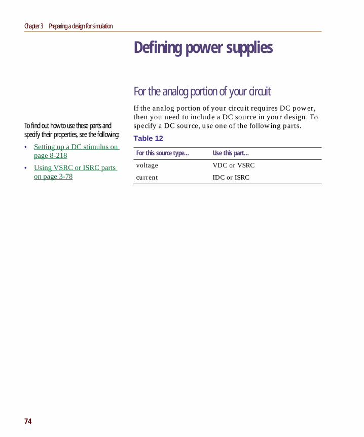
Defining power supplies
For the analog portion of your circuitIf the analog portion of your circuit requires DC power, then you need to include a DC source in your design. To specify a DC source, use one of the following parts.
Table 12
For this source type... Use this part...
voltage VDC or VSRC
current IDC or ISRC
To find out how to use these parts and specify their properties, see the following:
• Setting up a DC stimulus on page 8-218
• Using VSRC or ISRC parts on page 3-78
Pspug.book Page 74 Wednesday, November 11, 1998 1:14 PM
Defining stimuli
75
Defining stimuliTo simulate your circuit, you need to connect one or more source parts that describe the input signal that the circuit must respond to.
The OrCAD libraries supply several source parts that are described in the tables that follow. These parts depend on:
• the kind of analysis you are running,
• whether you are connecting to the analog portion of your circuit, and
• how you want to define the stimulus: using the Stimulus Editor, using a file specification, or by defining part property values.
Analog stimuliAnalog stimuli include both voltage and current sources. The following table shows the part names for voltage sources.
Table 13
If you want this kind of input... Use this part for voltage...
For DC analyses
DC bias VDC or VSRC
For AC analyses
AC magnitude and phase VAC or VSRC
For transient analyses
exponential VEXP or VSTIM*
periodic pulse VPULSE or VSTIM*
piecewise-linear VPWL or VSTIM*
piecewise-linear that repeats forever
VPWL_RE_FOREVER orVPWL_F_RE_FOREVER**
See Setting up a DC stimulus on page 8-218 for more details.
See Setting up an AC stimulus on page 9-233 for more details.
See Defining a time-based stimulus on page 10-252 for more details.
Pspug.book Page 75 Wednesday, November 11, 1998 1:14 PM
Chapter 3 Preparing a design for simulation
76
To determine the part name for an equivalent current source
1 In the table of voltage source parts, replace the first V in the part name with I.
Using VSTIM and ISTIMYou can use VSTIM and ISTIM parts to define any kind of time-based input signal. To specify the input signal itself, you need to use the Stimulus Editor. See The Stimulus Editor utility on page 10-253.
piecewise-linear that repeats n times
VPWL_N_TIMES orVPWL_F_N_TIMES**
frequency-modulated sine wave VSFFM or VSTIM*
sine wave VSIN or VSTIM*
* VSTIM and ISTIM parts require the Stimulus Editor to define the input signal.
** VPWL_F_RE_FOREVER and VPWL_F_N_TIMES are file-based parts; the stimulus specification is saved in a file and adheres to PSpice netlist syntax.
Table 13
If you want this kind of input... Use this part for voltage...
Example: The current source equivalent to VDC is IDC, to VAC is IAC, to VEXP is IEXP, and so on.
Pspug.book Page 76 Wednesday, November 11, 1998 1:14 PM
Defining stimuli
77
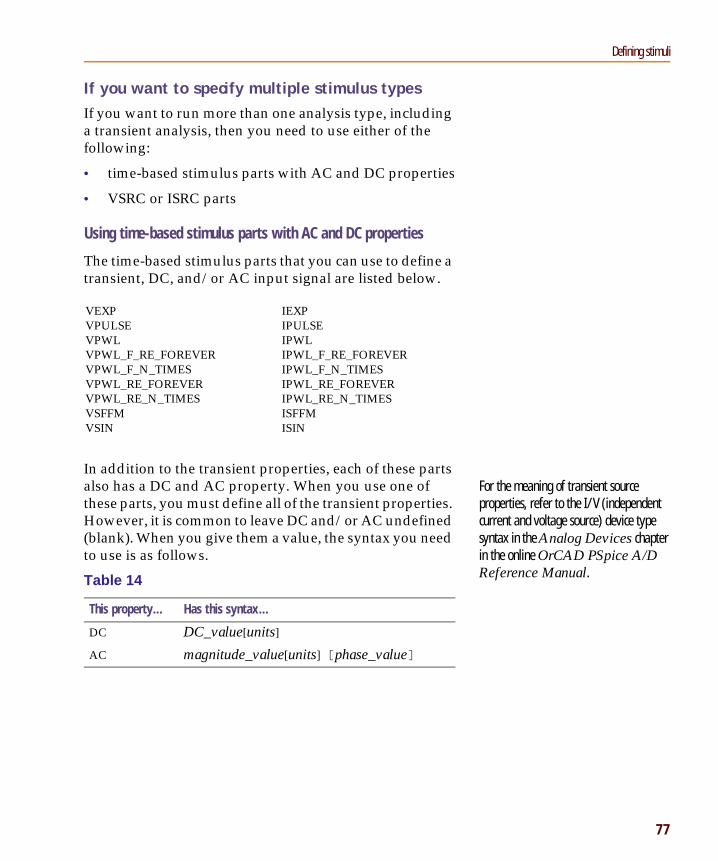
If you want to specify multiple stimulus typesIf you want to run more than one analysis type, including a transient analysis, then you need to use either of the following:
• time-based stimulus parts with AC and DC properties
• VSRC or ISRC parts
Using time-based stimulus parts with AC and DC properties
The time-based stimulus parts that you can use to define a transient, DC, and/or AC input signal are listed below.
In addition to the transient properties, each of these parts also has a DC and AC property. When you use one of these parts, you must define all of the transient properties. However, it is common to leave DC and/or AC undefined (blank). When you give them a value, the syntax you need to use is as follows.
For the meaning of transient source properties, refer to the I/V (independent current and voltage source) device type syntax in the Analog Devices chapter in the online OrCAD PSpice A/D Reference Manual.
Pspug.book Page 77 Wednesday, November 11, 1998 1:14 PM
Chapter 3 Preparing a design for simulation
78
Using VSRC or ISRC parts
The VSRC and ISRC parts have one property for each analysis type: DC, AC, and TRAN. You can set any or all of them using PSpice netlist syntax. When you give them a value, the syntax you need to use is as follows.
Note OrCAD recommends that if you are running only a transient analysis, use a VSTIM or ISTIM part if you have the standard package, or one of the other time-based source parts that has properties specific for a waveform shape.
Table 15
This property... Has this syntax...
DC DC_value[units]
AC magnitude_value[units] [phase_value]
TRAN time-based_type (parameters)where time-based_type is EXP, PULSE, PWL, SFFM, or SIN, and the parameters depend on the time-based_type.
For the syntax and meaning of transient source specifications, refer to the I/V (independent current and voltage source) device type in the Analog Devices chapter in the online OrCAD PSpice A/D Reference Manual.
Pspug.book Page 78 Wednesday, November 11, 1998 1:14 PM
Things to watch for
79
Things to watch forThis section includes troubleshooting tips for some of the most common reasons your circuit design may not netlist or simulate.
Unmodeled partsIf you see messages like this in the PSpice Simulation Output window,
Warning: Part part_name has no simulation model.
then you may have done one of the following things:
• Placed a part from the OrCAD libraries that is not available for simulation (used only for board layout).
• Placed a custom part that has been incompletely defined for simulation.
Do this if the part in question is from the OrCAD libraries• Replace the part with an equivalent part from one of
the libraries listed in the tables below.
• Make sure that you can simulate the part by checking the following:
• That it has a PSPICETEMPLATE property and that its value is non-blank.
• That it has an Implementation Type = PSpice MODEL property and that its Implementation property is non-blank.
For a roadmap to other commonly encountered problems and solutions, see When netlisting fails or the simulation does not start on page 3-58.
The libraries listed in the tables that follow all contain parts that you can simulate. Some files also contain parts that you can only use for board layout. That’s why you need to check the Pspice TEMPLATE property if you are unsure or still getting warnings when you try to simulate your circuit.
Pspug.book Page 79 Wednesday, November 11, 1998 1:14 PM
Chapter 3 Preparing a design for simulation
80
Table 16
Analog libraries with modeled parts (installed in Capture\Library\PSpice)To find out more about a particular library, refer to the online Library List or read the header of the model library file itself.
1_SHOT
ABM
ADV_LIN
AMP
ANALOG
ANA_SWIT
ANLG_DEV
ANL_MISC
APEX
BIPOLAR
BREAKOUT
BUFFER
BURR_BRN
CD4000
COMLINR
DIODE
EBIPOLAR
EDIODE
ELANTEC
EPWRBJT
FILTSUB
FWBELL
HARRIS
IGBT
JBIPOLAR
JDIODE
JFET
JJFET
JOPAMP
JPWRBJT
JPWRMOS
LIN_TECH
MAGNETIC
MAXIM
MOTORAMP
MOTORMOS
MOTORSEN
MOTOR_RF
NAT_SEMI
OPAMP
OPTO
PHIL_BJT
PHIL_FET
PHIL_RF
POLYFET
PWRBJT
PWRMOS
SIEMENS
SWIT_RAV
SWIT_REG
TEX_INST
THYRISTR
TLINE
XTAL
ZETEX
Pspug.book Page 80 Wednesday, November 11, 1998 1:14 PM
Things to watch for
81
Check for this if the part in question is custom-builtAre there blank (or inappropriate) values for the part’s Implementation and PSPICETEMPLATE properties?
If so, load this part into the part editor and set these properties appropriately. One way to approach this is to edit the part that appears in your design.
To edit the properties for the part in question
1 In the schematic page editor, select the part.
2 From the Edit menu, choose Part.
The part editor window appears with the part already loaded.
3 From the Edit menu, choose Properties and proceed to change the property values.
Unconfigured model, stimulus, or include filesIf you see messages like these in the PSpice Simulation Output window,
(design_name) Floating pin: refdes pinpin_name
Floating pin: pin_id
File not found
Can’t open stimulus file
or messages like these in the PSpice output file,
Model model_name used by device_name isundefined.
Subcircuit subckt_name used by device_nameis undefined.
Can’t find .STIMULUS “refdes” definition
then you may be missing a model library, stimulus file, or include file from the configuration list, or the configured file is not on the library path.
To find out more about setting the simulation properties for parts, see Defining part properties needed for simulation on page 5-139.
To find out more about using the part editor, refer to your OrCAD Capture User’s Guide.
Pspug.book Page 81 Wednesday, November 11, 1998 1:14 PM
Chapter 3 Preparing a design for simulation
82
Check for this• Does the relevant model library, stimulus file, or
include file appear in the configuration list?
• If the file is configured, does the default library search path include the directory path where the file resides, or explicitly define the directory path in the configuration list?
If the file is not configured, add it to the list and make sure that it appears before any other library or file that has an identically-named definition.
To view the configuration list
1 In the Simulation Settings dialog box, click the Include Files tab.
If the directory path is not specified, update the default library search path or change the file entry in the configuration list to include the full path specification.
To view the default library search path
1 In the Simulation Settings dialog box, click the Libraries tab.
Unmodeled pinsIf you see messages like these in the PSpice Simulation Output window,
Warning: Part part_name pin pin_name isunmodeled.
Warning: Less than 2 connections at nodenode_name.
or messages like this in the PSpice output file,
Floating/unmodeled pin fixups
then you may have drawn a wire to an unmodeled pin.
To find out more about how to configure these files and about search order, see Configuring model libraries on page 4-120.
To find out more about the default configuration, see How are models organized? on page 4-88.
To find out more about the library search path, see Changing the library search path on page 4-125.
Pspug.book Page 82 Wednesday, November 11, 1998 1:14 PM
Things to watch for
83
The OrCAD libraries include parts that are suitable for both simulation and board layout. The unmodeled pins map into packages but have no electrical significance; PSpice ignores unmodeled pins during simulation.
Check for thisAre there connections to unmodeled pins?
If so, do one of the following:
• Remove wires connected to unmodeled pins.
• If you expect the connection to affect simulation results, find an equivalent part that models the pins in question and draw the connections.
Missing groundIf for every net in your circuit you see this message in the PSpice output file,
ERROR -- Node node_name is floating.
then your circuit may not be tied to ground.
Check for thisAre there ground parts named 0 (zero) connected appropriately in your design?
If not, place and connect one (or more, as needed) in your design. You can use the 0 (zero) ground part in SOURCE.OLB or any other ground part as long as you change its name to 0.
To find out more about searching for parts, see Finding the part that you want on page 3-62.
Pspug.book Page 83 Wednesday, November 11, 1998 1:14 PM
Chapter 3 Preparing a design for simulation
84
Missing DC path to groundIf for selected nets in your circuit you see this message in the PSpice output file,
ERROR -- Node node_name is floating.
then you may be missing a DC path to ground.
Check for thisAre there any nets that are isolated from ground by either open circuits or capacitors?
If so, then add a very large (for example, 1 Gohm) resistor either:
• in parallel with the capacitor or open circuit, or
• from the isolated net to ground.
Example: The circuit shown below connects capacitors (DC open circuits) such that both ends of inductor L2 are isolated from ground.
When simulated, PSpice flags nets 2 and 3 as floating. The following topology solves this problem.
Note When calculating the bias point solution, PSpice treats capacitors as open circuits and inductors as short circuits.
Pspug.book Page 84 Wednesday, November 11, 1998 1:14 PM