37 Psychrornetry I. introduction- 2. Psychrometric Terms. 3. Dalton's Law of Partial Pressures. 4. Psychrometric Rarions. .5. EntPoJpy (Total Heat) of Moist Air. 6 Thermodynamic Wet Bulb Temperature or Adiabatic SQturalion Temperature. 7. Psychrometric Chart. 8. Psychrometric Processes. 9. Sensible Cooling. 10. Sensible Heating. 11. Humidification and Dehwnidiflcation. 12. Sensible Heat Factor. 13. Cooling and Dehumidjfjca tion . 12. Heating and Hwnid(fication. 15. Adiabatic Miring of Two Air Streams. - W.I. Introduction The psychrometly is that branch of engineering science, which deals with the study of moist air Le. dry air mixed with water vapour or humidity. It also includes the study of behaviour of dry air and water vapour mixture under various sets of conditions. Though the earth's atmosphere is a mixture of gases including nitrogen (N 2). oxygen (02). argon (At) ad carbon dioxide (CO2), yet for the purpose of psychrometry, it is considered to be a mixture of dry air and water vapour only. p.2. Psychrometric Terms Tough there are many psychrometric terms, yet the following are important from the subject point of view: I'. Thy air. The 6 iure dry air is a mixture of number of gases such as nitrogen, oxygen, nrbori-dioxide, hydrogen, argon, neon, helium etc. But the nitrogen and oxygen have the major portion of the combination. The dry air is considered to have the composition as given in the following table. Table 37.1. Composition of dry air. S.No. I Constituent 1. Nitrogen (Ni) 2. Oxygen (02) 3. Argon (At) 4. Carbon-dioxide (CO2) Byyo!ume By mass 78.03% 75.47% 20.99% 23.19% 0.94% 1.29% 0.03% 0.05% 5. Hydrogen (Ib) 0.01% I The molecular mass of dry air is taken as'28.966 and the gas constant for air (R) is equal to 0.287 Id/kg K. Notes: :a) The pure dry air does not, ordinarily, exist in nature because it always contain some water vapour. (b) The term air, wherever used in this text, means dry air containing moisture in the vapour form. (c) Both dry air and water vapour can be considered as perfect gases because both exist in the atmosphere at low pressure. Thus all the perfect gas terms can be applied to them individually. (d) The density of dry air is taken as 1.293 kg/m 3 at pressure 1.0135 bar or 101.35 kN/m 2 and at temperature O' C (273 K). 799
Transcript
37
Psychrornetry
I. introduction- 2. Psychrometric Terms. 3. Dalton's Law of Partial Pressures. 4. PsychrometricRarions. .5. EntPoJpy (Total Heat) of Moist Air. 6 Thermodynamic Wet Bulb Temperature or AdiabaticSQturalion Temperature. 7. Psychrometric Chart. 8. Psychrometric Processes. 9. Sensible Cooling. 10.Sensible Heating. 11. Humidification and Dehwnidiflcation. 12. Sensible Heat Factor. 13. Cooling andDehumidjfjcation. 12. Heating and Hwnid(fication. 15. Adiabatic Miring of Two Air Streams. -
W.I. IntroductionThe psychrometly is that branch of engineering science, which deals with the study of moist
air Le. dry air mixed with water vapour or humidity. It also includes the study of behaviour of dry airand water vapour mixture under various sets of conditions. Though the earth's atmosphere is a mixtureof gases including nitrogen (N 2). oxygen (02). argon (At) ad carbon dioxide (CO2), yet for thepurpose of psychrometry, it is considered to be a mixture of dry air and water vapour only.
p.2. Psychrometric TermsTough there are many psychrometric terms, yet the following are important from the subject
point of view:I'. Thy air. The 6iure dry air is a mixture of number of gases such as nitrogen, oxygen,
nrbori-dioxide, hydrogen, argon, neon, helium etc. But the nitrogen and oxygen have the majorportion of the combination.
The dry air is considered to have the composition as given in the following table.
The molecular mass of dry air is taken as'28.966 and the gas constant for air (R) is equal to
0.287 Id/kg K.Notes: :a) The pure dry air does not, ordinarily, exist in nature because it always contain some water vapour.
(b)The term air, wherever used in this text, means dry air containing moisture in the vapour form.
(c) Both dry air and water vapour can be considered as perfect gases because both exist in the atmosphereat low pressure. Thus all the perfect gas terms can be applied to them individually.
(d)The density of dry air is taken as 1.293 kg/m3 at pressure 1.0135 bar or 101.35 kN/m 2 and attemperature O' C (273 K).
799
799
2. Moist ,fr. It is a mixture of dry air and water vapour. The amount of water vapour,present in the air, depends upon the absolute pressure and temperature of the mixture.
3. Soturrited air. It is a mixture of dry air and water vapour, when the air has diffused themaximum amount of water vapour into it. The water vapours, usually, occur in the form of superheatedsteam as an invisible gas. However, when the saturated air is cooled, the water vapour in the air startscondensing, and the same maybe visible in the form of moist, fog or condensation on cold surfaces.
4 /)ei.'rr'e o(sotri,ahion. It is the ratio of actual mass of water vapour in a unit mass of dryair to the mass of water vapour in the same mass and pressure of dry air when it is saturated at thesame temperature.
5. lIu,niditv. It is the mass of water vapour present in I kg of dry air, and is generallyexpressed in terms of gm per kg of dry air. It is also called specific humidity or humidity ratio.
(s. Absolute humidit y. It is the mass of water vapour present in I m3 of dry air, and isgenerally expressed in terms of gm per cubic metre of dry air. It is also expressed in terms of grainsper cubic metre of dry air. Mathematically, one kg of water vapour is equal to 15430 grains.
7. Re/ative humidity. It is the ratio of actual mass of water vapour in a given volume ofmoist air to the mass of water vapour in the same volume of saturated air at the same temperature andpressure.
l. Dr-s bulb temperature. It is the temperature of air recorded by a thermometer, when it isnot affected by the moisture present in the air. The dry bulb temperature is generally denoted by ror
9. Wet bulb temperature. It is the temperature of air recorded by a thermometer, when itsbulb is surrounded by a wet cloth exposed to the air. Such a thermometer is called Wet bulbthermometer. The wet bulb temperature is generally denotedby ç or ç,,.
10. Wet bulb depression. It is the difference be-tween dry bulb temperature and wet bulb temperature at any
Handle
point. The wet bulb depression indicates relative humidity ofthe air.
II. Dew poi,f tempevalure. It is the temperature ofair recorded by a thermometer, when the moisture (watervapour) present in it begins to condense. In other words, thedew point temperature is the saturation te.iperature (t,,) cor-responding to the partial pressure of water vapour (p). It is. Wetusually, denoted by tdp thermNote For saturated air, the dry bulb temperature, wet bulb tem-perature and dew point temperature is same.
12. Dw pain! depression. It is the difference be-tween the dry bulb temperature and dew point temperature ofair..
II. Psv( /t,o,netcr. There are many types of psy-chrometers, but the sling payshrometer, as shown in Fig. 37.1,is widely used. It consists of a dry bulb thermometer and a wet Fig 37.1. Sling psychrometer.
* A wet bulb thermometer has its bulb covered with a niece of s.rfl cloth for silk wick) which is exposed tothe air. The tower part of this cloth is dipped in a small basin of water. The water from the basin rises upin the cloth by the capillary action, and then gets eaporatcd. It may be noted that if relative humidity ofair is high (i.e. the air contains more watervapour), there will be little evaporation and thus there will be asmall cooling effect. On the other hand. if relative humidity of air is low (i.e. the ar contains less Water
apour), there %% ill he more cvajoralion and thus there will be more cooling effect.
Dry bulb
Bulb covetedwith wetted
wick
gyj A Text Book of The, ma! Engineering
bulb thermometer mounted side by side in a protective case that is attached to a handle by a swivelconnection so that the case can be easily rotated. The dry bulb thermometeris directly exposed to airand measures the actual temperature of the air. The bulb of the wet bulb thermometer is cc'ered bya wick thoroughly wetted by distilled water. The temperature measured by this wick covered bulb ofa thermometer is the temperature of liquid water in the wick and is called wet bulb temperature.
The sling psychrometer is rotated in the air for approximately one minute after which thereadings from both the thermometers are taken. This process is repeated several times to assure thatthe lowest I &ssible wet bulb temperature is recorded.
373. Dalton's Law of Partial PressuresIt states, "The Iotal pressure exerted by the mixture of air and water vapour is equal to the
sum of the pressures, which each constituent would exert, if it occupied the same space by itself'. Inother words, the total pressure exerted by air and water vapour mixture is equal to the barometricpressure. Mathematically, barometric pressure of the mixture,
Pb = Po+Pvwhere p = Partial pressure of dry air, and
= Partial pressure of water vapour.
37.4. Psychrometric Relations
We have aircady discussed some psychrometric terms in Art. 37.2. These terms have somerelations between one another. The following psychrometric relations are important from the subjectpoint of view:
I. Humidity, specific or absolute humidity, humidity ratio or moisture content. It is thethass of water vapour present in 1 kg or iry air and is generally expresed in kg/kg of dry air. It mayalso be defined as the ratio of mass of water vapour to the mass of dry air in a given volume of theair-vapour mixture. Mathematically,
Humidity, specific or absolute humidity, humidity ratio or moisture conetnt,
W = 0.622x =P. PP
where p,, = Partial pressure of water vapour,
p. = Partial pressure of dry air, and
Ph = Barometric pressure.
For saturated air (i.e. when the air is holding maximum amount of water vapour), the humidityratio or maximum specific humidity,
= W,,., = 0.622 xPb P,
where p, = Partial pressure of air corresponding to saturation temperature(i.e. dry bulb temperature, t)
2. Degree of saturation or percentage humidify. We have already discussed that the degreeof saturation is the ratio of actual mass of water vapour in a unit mass of dry air to the mass of watervapour ia the same mass of dry air when it is saturated at the same temperature (dry bulb temperature).In other words, it maybe defined as the ratio of actual specific humidity to the si • cific humidity ofsaturated air at the same dry bulb temperature. It is, usually, denoted by j.t.
Psych ro,netry
Mathematically, degree of saturation.0.622 p,
W PP- - 0.622p
Ph - P,
- - P Pb
PLPhP) p, 1 1i'
LPb
Notes: (a) The partial pressure of saturated air ( p,) is obtained from the steam tables corresponding to thy bulbtemperature I,,.
(b) If the relative humidity, 4) = p,, Ip, is equal to zero, then the humidity ratio, W U, i.e., for dry air,
degree of saturation p = 0.(c) If the rc,lative humidity, 0 = p Ip, is equal to 1, then W= W,, and p = I Thus. de2nc of saturation,
It varies between 0 and I.3. Relative humidity. We have already discussed that the relative humidity is the ratio of
actual mass of water vapour (m),) in a given volume of moist air to the mass of water vapour t,n,) in
the same volume of saturated air at the same temperature and pressure.The relative humidity may also be defined as the ratio of actual ptiaI pressure of water vapour
in moist air( p) at a given temperature (dry bulb temperature) to the saturation pressure (p) of water
vapour (or partial pressure of water vapour in saturated air) at the same temperature. It is usuallydenoted by 4) . Mathematically, relative humidity,
fl,5 Pu' mp,
The relative humidity may also be obtained as discussed below:We know that degree of saturation,
l&P, Pt, Pb
11- l-4)x
Pb Pb
4)-p
Pb
Note: For saturated air, the relative humidity is IIX)%.4. Pressure of water vapour. According to Carrier's equation, the partial pressure of water
vapour,- (pt,_p) (t— t,)
1544—l.44ç
where p5, = Saturation pressure corresponding to wet bulb temperature (fromsteam tables),
Pb = Barometric pressure,
802 .4 Tea Book of Thermal EngineeringId = Dry bulb temperature, and
= Wet bulb temperature.
5. Vapour fr'isity or absolute hwniditv We have already discussed that the vapour densityor abso'ute numidity is the mass of water vapour present in I m3 of dry air. Mathematically, vapourdensity or absolute humidity,
- W(p_p)
- R - .. . C. p = P. +p)T R T
where p0 = Pressure of air in kNIm2,
W = Humidity ratio,
R0 = Gas constant for air 0.287 kJ/kg K, and
= Dry bulb temperature in K.
Example 37.1. The atmospheric air has a dry bulb temperature of 210 C and wet bulbtemperature 16° C. lithe barometer reads 750 mm of Jig, determine: I. partial pressure of watervapour; 2. Relative humidity; and 3. Dew point temperature.
Solution. Given: td = 21°C ç= 18°C ;Pb=750 nmofHg
1,. Partial pressure of water vapour
From steam tables, we find that saturation pressure of vapour corresponding to wet bulbtemperature of 18° C, is
= 0.02062 bar = 0.001330,02062 -
- 15.5 rnrnofHg.
... (.lmmofHg=0.00l33bj)
We know that partial pressurc of water vapour,
(pb--p,)Od--c)pv = l544-1.44ç
153_15.5)(2I_18)
1544- x 18 = 14 mm of Hg Ans.
2. Relative humidityFrom steam tables, we End that saturation pressure of vapour, corresponding to thy bulb
temperature of 21° C, is
p = 0.02485 bar = 0248S 0.00133 = 18.7 mm of Hg
We know that relative humidity.
= =18.7 = 0.748 or 74 % Ans.
3.Dew point temperatureWe know that dew point temperature has a saturation pressure equal to the pressure of water
vapour in the air. Front tables, we find that the temperature corresponding to 14 mm of Hg is16.4°C. Therefore dew point temperature,
=
IdP = 16.4°C Ans.
Ps y chro,net,y 803
Example 37.2. A sling psychrometer gives reading of 25 C dry bulb temperature and 15°C we: bulb temperature. The barometer indicates 760 nun ofllg. Assuming portial pressure of thevapour as 10 mm of Hg, detennine: 1. Specific humidity, and 2. Saturation ratio.
A Teu Book of Thermal EngineeringThe term(c,,, + Wc) is called humid specific heat (ca,,). It is the specific heat or heat capacity
of moist air, i.e. (I + W) kg/kg of dry air. At low temperature of air conditioning range, the value ofWis very small. The general value, of humid specific heat in air conditioning range is taken as 1.022kJ/kgK.
h = 1.022td + W Ihf8 +(4 2_I9)tdP] ...c = l9 kJ/kg K)
= I.022td+W[hP+2.3:,,,,1kJwhere
h1,, = Latent heat of vaporisation of water corresponding to dew point tem-perature (from steam tables).
Example 37.3. A sleeve psychrometer reads 40° Cdry bulb temperature and 28° C wet bulbtemperature. Assuming the barometric pressure as 1.013 bar, determine 1. Humidity ratio ; 2.Relative humidity; 3. Dew point temperature; and 4. Entl'alpy of the mixture per kg of dry air.
Solution. Given :td =40°C; z =28° C ; ph = 1.013 bar
I. Humidity ratioFirst of all, let us find the partial pressure of vapoui s, p. From steam tables, we find that the
Saturation pressure corresponding to wet bulb temperature of 28°C is0.037 78 bar
(Pb - p,,) (td - ç)'Va'
= 0.03778— (1.013-0.03778) (4O21544— I.44x28
0.03778—O.t0778 = 0.03 bar Ans.
We know that humidity ratio,
w=0622i
0.622x0.03 = 0.019kg/kg of dry air Ans.=Ph - P 1.013-0.03
2. Relative humidityFrom steam tables, we find that the saturation pressure of vapour, corresponding to dry bulb
temperature of 40°C isp, = 0.07375 bar
Reiative humidity,
P 0.03= p, = 0.07375 = 0.407 or 40.7% Ans.
3. Dew point temperatureSince the dew point temperature is the saturation temperature corresponding to the partial
pressure of water vapour (pr,), therefore from steam tables, corresponding to 0.03 bar, dew pointtemperature is
t,1 = 24°C Ans.
4. Enthalpy of mixture per kg of dty airFrom steam tables, we find that the latent heat of vaporisation of water at dew point
temperature of 24° C ishjg4, = 2445 kJ/kg
Psychrometry 805
Enthalpy of mixture per kg of dry air,
= 1.022 td W [hj a+ 2.3 t4J
= L022x40+0.019[2445+2.3x241 kJ/kg of dry air
88.4 kJlkg of dry air Ans.
Example 37.4, In a laboratory test, a sling psychrometer recorded dry bulb and wet bulbtemperatures as 30° C and 25° C respectively. Catcu!ate 1. vapour pressure, 2. relative humidity,3. specific humidity, 4. degree of saturation, 5. dew point temperature, and 6. enthalpy of the mixture.
Solution. Given: = 30°C; ç = 25°C
I. Vapour pressure
From steam tables, we find that saturation pressure of vapour corresponding to wet bulbtemperature of 250 C is
p. = 0.03166 bar
We know that vapour pressurc, (
TI- p,,) ('d - ç)P, 1
71 .I—l.44ç
= 01 66— (1.01330.031 66)(30-25)1544— I.44x25
= 0.03166 — 0,003 26 = 0.0284 bar Arts.
2. Relative humidity
From steam tables, we also find that the saturation pressure of vapour at 30°C.
= 0.042 42 bar
We know that relative humidity,
= p, = 0.04242 0.66 or 66% Ans.
3. Specific humidity
We know that specific humidity,
0.622 p'
0.622 x 0.0284W = = kg/kg of dry air
(PbPr) 1.0133-0.0284
= 0.018 kg / kg of dry air Ans.
4. Degree afsaturnt,o,,
We know that degree of saturation,
i' (Pb -
-0.0284(l.0133-0.04242)
= 004242(1.0133 - 0.0284)) 0.651 Aits.
5. l)ew poizi u,nj,erature
We know that dew point temperature has a saturation pressure equal to the pressure of watervapour in the air. From steam tables, we find that the temperature corresponding to 0.0284 bar is 23°C. Therefore dew point temperature,
tdp = 23°C Arts.
806
A Te.t I Book of Thermal Engineering
6. Enthalp) of the ,ni4 tore
From steam tables, we find that the latent heat of vaporisation of water at dew pointtemperature of 23° C. is
= 2447.21(1/kg
Enthalpy of the mixture
= 1.022td+W(/,+2.3t*)
= 1.022 x 30+0.018(2447.2+2.3 x 23)= 7566 kJ Ans.
37.6. Thermodynamic Wet Bulb Temperature or Adiabatic Saturation Temperature
The thermodynamic wet bulb temperature or adiabatic saturation temperature is the tempera-ture at which the air can be brought to saturation stale, adiabatically, by the evaporation of water intothe flowing air.
The equipment used for the adiabatic saturation of air, in its simplest form, consists of aninsulated chamber containing adequate quantity of water. There is also an arrangement forextra water(known as make-up water) to flow into the chamber from its top, as shown in Fig. 37.2
(Wa - W) .t,h,,,,Make up water Ins Ialed chamber
Unsaturated air -_.e.ft3 -Saturated airh,WId
-- Wat(() t)2.
Fig. 37.2. Adiabatic saturation of air.
Let the unsaturated air eiters the chamber at section I. As the air passes through the chamberover a long sheet of water, the water evaporates which is carried with the flowing stream of air, andthe specific humidity of the air increases. The make up vater is added to the chamber at thistemrature to make the water level constant. Both the air and water are cooled as the evaporationtakes place. This process continues until the energy transferred from the air to the water is equal tothe energy required to vaporise the water. When steady conditions are reached, the air flowing atsection 2 is saturated with water vapour. The temperature of the saturated air at section 2 is knownas thermodynamic we: bulb temperature or adiabatic saturation temperature.
The adiabatic saturation process can be represented on T-s diagram as shown by the curve 1-2in Fig. 37.3. During the adiabatic saturation process, the partial pressure of vapour increases, althoughthe total pressure of the air-vapour mixture remains constant. The unsaturated air initially at dry bulbtemperature tdl is cooled adiabatically to dry bulb temperature t, which is equal to the adiabaticsaturation temperature ç. It may be noted that the adiabatic Saturation temperature is taken equal tothe wet bulb temperature for all practical purposes.
Enthalpy of unsaturated air at section l,
W1 = Specific humidity of air at section I,
h2, % = Corresponding values of saturated air at section 2. and
= Sensible heat of water at adiabatic saturation temperature.
PschronIetIV 807
Balancing the enthalpies of air at inlet and outlet (i.e. at sections 1 and 2),• (I)
• (ii)111+(W2— WI) hfr = h2
or h1—W1ht. = h2 W2
Sat. air
Entropy
Unsaturated air (Initial condition)
Adiabatic saturation process
OnSlaflI pressure cooling
point of unsaturated air all
Fig. 37.3. T.sdiagram for adiabatic saluration process.
The term (h2 - W2 h) is known as sigma heat and remains constant during the adiabatic
process.
We know that h1 =h1+W1h,1
and = h02+W2h,2
where h1 = Enthalpy of I kg of dry air at dry bulb temperature t,.= Enthalpy of superheated vapour at :, per kg of vapour,
h 2 = Enthalpy of 1 kg of air at wet bulb temperature ç, and
h 2 = Enthalpy of saturated vapour at wet bulb temperaturc ç per kg
of vapour.
Now the equation (ii) may be written as
(h 1 + W1 h 1 ) - W1 h1,, = (h 2 + W2 h 2) - W2 h
hf.
W, (h,, ._h) W..(h,2_hfr)+hdZhaI
WI =- h1_
Example 375. Atmospheric air at 0.965 bar enters the adiabatic saturator. The wet bulbtemperature is 20° C and dry bulb temperature is 31° C during adiabatic saturation process.Determine I. humidity ratio of the entering air, 2. vapour pressure and relative humidity at 31 0 C,and 3. dew point temOerature.
Solution. Given :p,=0.965 bar; ç = 20°C; t d = 31'C
In psychromctry, the enthalpy of superheated vapour at dry bulb temperature I d , is taken equal to theenthalpy of saturated vapour corresponding to dry bulb temperature td]:
808 A Text Book of Thermal EngineeringI. Humidity ratio of the entering air
Let W1 = Humidity 13110 of the entering, air, and
W2 Humidity ratio of the saturated air.First of all, let us find the value of W2 . From steam tables, we find that saturation pressire of
vapour at 20° C,P, = 0.02337 bar
Enthalpy of saturated vapour at 20° C,
= Jig? = 2538.2 Id/kg
Sensible heat of water at 20'C,h = 83.9 kJ/kg
and enthalpy of saturated vapour at 31°C,
= h 1 = 2558 rkJ/kg
We know that enthalpy of unsaturated air corresponding to dry bulb temperature of 3j0 C,= mc,,:,, = IXI,005x3l = 31.155kJ/kg
... (Taking c,, for air =t.005kJflcK)Enthalpy of' kg of saturated air corresponding to wet bulb temperature of 20° C,
h,,2 = mc,,ç = Ix 1.005x20 = 20.1 kJ/kg
O.622p2 0622x002337Wc know that W2 - = 0965002337 = O.0154kg/kgof dry air
- W2(h,2—h)+h,,2—h1h,1—hfr
- 0.0154(2538.2-83.9)+20.1 —31.1552558.2-83.9
0.OlO8kg/kgof dry air Ans.2. Vapour pressure and relative humidity a( 31 ' C
Let p,,1 = Vapour pressure at3l°C.
O.622pWe know that W1 =
0.01080.622p
=0.965 —p1
0.0I04-0.0I08p 1 = 0.622p,,1
p,, 1 0.0164 bar Ans.
From steam tables, we find thatthe saturation pressure corresponding to dry bulb temperatureof 3 1° C is
p3 = 0.04491 bar
P,,1 0.0164
Relative humidity, 4 == 0.04491 = 0.365 or 36.5% Ans.
Psych rornetry 809
3. Dew point temperatureSince the dew point temperature (zdP) is the saturation temperature corresponding to the partial
pressure of water vapour (pd ). therefore from steam tables, corresponding to 0.0164 bar, we find that
tdp = 14.5°C Arts.
37.1. Psychrometric Chart
It is a graphical representa. on of the various thermodynamic properties of moist air. Thepsychrometric chart is very usefu l for finding Out the properties of air (which are required in the fieldof air conditioning) and eIimirit .. lot of calculations. There is a slight variation in the charts preparedby different air-conditioning ;anufactures but basically they are all alike. The psychrometric chartis normally drawn for stanrrd atmospheric pressure of 760 mm of Hg (or 1.01325 bar).
Dry bulb temperature ('C) _
Fig. 37.4. Psychrometric chart.
a'a
In a psychrometric chart, dry bulb temperature is taken as abscissa and specific humidity i.e.moisture contents as ordinate as shown in Fig. 31.4. Now the saturation curve is drawn by plottingthe various saturation points at corresponding dry bulb temperatures. The saturation curve represents100% relative humidity at various dry bulb temperatures. It also represents the wet bulb and dewpoint temperatures.
Though the psychrometric chart has a number of details, yet the following lines are importantfrom the subject point of view:
I. Dry bulb temperature lines. The dry bulb temperature lines are vertical i.e. parallel tothe ordinate and uniformly spaced as shown in Fig. 37.5. Generally, the temperature range of theselines on psychrometric chart is from — 6°C to 45'C. The dry bulb temperature lines are drawn withdifference of every 5°C and up to the saturation c'Jrve as shown in the figure. The values of dry bulbtemperature are also shown on the saturation curve.
2. Specific humidity or moisture content lines. The specific humidity (moisture content)lines are horizontal i.e. parallel to the abscissa and are also uniformly spaced as shown in Fig. 37.6.Generally, moisture content range of these lines on psychrometric chart is from 0 to 30 g / kg of dry
air (Or from 0 to 0.030 kg / kg of dry air). The moisture cot cnt lines are drawn with a difference ofevery I g (or 0.001 kg) and up to the saturation curve as shown in the figure.
Fig. 375. Dry bulb temperature lines. 1-ig.37,6, Specific humidit y lines.
3. Dew paint temperature lines. The dew point temperature Ii s are horizontal i.e. parallelto the abscissa and non-uniformly spaced as shown in Fig. 37.7. At any :-,in[ on the saturation curve,the dry bulb and dew point temperatures are equal.
The values of dew point temperatures are generally given along the saturation curve of thechart as shown in the figure.
Ib
V4 4%1`1111̂ Dew
:nuemh
-6 5 15 25 3545—Dry bulb temperature, 'C—.-
Fig. 37.7. Dew point temperature lines.
1'-o a Ia £3 j3
—Dry bulb temperature, C—.
Fig. 37.8. Wet bulb temperature lines.
4. Wet bulb temperatures lines. The wet bulb temperature lines are inclined straight linesand non-uniformly spaced as shown in Fig. 37.8. At any point on the saturation curve, the dry bulband wet bulb temperatures are equal.
The values of wet bulb temperatures are generally given along the saturation curve of the chaEtas shown in the figure.
5. Enthalpv (total heat) lines. The enthalpy (or total heat) li:.es are inclined straight linesand uniformly spaced as shown in Fig. 37.9. These lines are parallel to the wet bulb temperature lines,and are drawn up to the saturation curve. Some of these lines coincide with the wet bulb temperaturelines also.
The values of total enthalpy are given on a scale above the saturation curve as shown in thefigure.
6. Specific volume hues. The specific volume lines are obliquely inclined straight lines anduniformly spaced as shown in Fig. 37.10. These lines are drawn up to the saturation curve.
The values of volume lines are generally given at the base of the chart.
—Dry bulb temperature- —Dry bulb temperature
0
3=0.
E
0.(0
Fig. 37.11). Specific voirinre lines.Fig. 37.9. Enthalpy line,.
0EEC
PscIt lo,neti 811
7. Vapoutpresure Im. The vapour pressure lines are horizontal and uniformly spaced.Generally, the vapour pressure tines are not drawn in the main chart. But a scale showing vapourpressure in nun of Hg is given on the extreme left side of the chart as shown in Fig. 37.11.
S. ks'!aise humidity lines. The relative humidity lines are curved lines and follows thesaturation curve. Generally, these lines are drawn with values 10%, 20%, 30% etc., and upto 100%.The saturation t.Jrve represents 100% relative humidity. The values of relative humidity lines aregenerally given along the lines themselves as shown in Fig. 37.12.
Example 37.6. A:mospheri. , air at 760 mm of Hg barometric pressure has 25° C dry bulbtemperature and 15° C wet bulb temperature. By using psychrometric chart, determine: 1. Relativehumidity, 2. Humidity ratio, and 3. Dew point temperature.
Solution, p=760mmofHg;t ,,=25°C;ç= 15°C
The initial condition of the air, i.e. 25°C dry bulbtemperature and 15°C wet bulb temperature is marked onthe psychrometric chart at point P as shown in Fig. 37.13.
I. Relative humidityThe relative humidity, as read along the relative
humidity curve, is 35%. Ans.
2. Humidity ratioFrom point P. draw a horizontal line meeting the
humidity ratio line at point Q, as shown in Fig. 37.13. Now,the humidity ratio, as read on the scale at point Q, is 6.7g /..kg of dry air. Ads.
Superli usnis dan.
Sat, curve L35%
25-Dry bulb temperature,'C'
Fig. 37.13
12 .1 rext licol: at Ii/le,nial Engineen4g
3. Dew point temperature
From point I', draw a horizontal Tine meeting the saturation curve at point R, as shown inFig. 37.11 Now, the dew point temperature, as read on the saturation curve at point R is 8° C
Note: The dew point temperature may also be read on the dry bulb temperature scale. From point!?, draw avertical line meeting the dry bulb temperature scale at point S, as shown in Fig. 37.13. Now the reading at pointS is 8° C.
Example 37.7. With the help of psychrometric chart, find.' I. dew point temperature 2.Enthalpy; and 3. Vapour pressure Ofair having a dry bulb temperature of3fl° C and O% relative
hi:'nidity.
Solution. Given: rd = 300 C; 4' = 509o'
The initial condition ofair, i.e. 30°Cdry bulb temperature and 50% relative humidity is markedon the psychrometric chart at point P. as shown in Fig. 37.14.
I. Dew point zemperatue
From point P. draw a horizontal line meetingthe saturation curveat point Q. as shown in Fig. 37.14.Now the dew point temperature, as read on the satu-ration curve at point Q, is 18.5° C. Ans.
2. Enthalpy
From point P. draw a line parallel to enthalpyline (or wet bulb line) meeting the enthalpy scale atpoint R. Now the enthalpy as read on the scale at pointR is 64.7 kJ I kg of dry air. Ans.
3. Vapour pre.cure
NPA50%
1sz E
P
C
r0
- Dry bulb ierperatwe.0
Fig. 3714
Extend the horizontal line PQ to meet the vapcuf pressure scale at point S. Now the vapour
pressure, as read on the scale at point S, is 16 into of Hg. Ans.
37.8. P.sychronictric Processes
Though there are many psychrometric processes, yet the following are important from the
subject point ofview:
I. Sensible cooling. 2. Sensible heating. 3. Humidification and dehumidification.
We shall now discuss these processes, in detail, in the following pages.
37.9. Sen'ible Cooling
The cooling of air, without any change in its specific humidity, is known as sensible cooling.
Let air at temperature'di passes over a cooling coil of temperature z, as shown in Fig. 37.15 (a). A
little consideration will show that the temperature of air leaving the cooling coil (t, ) will be more
than ç. The process of sensible cooling, on the psychrometric chart, is shown by a horizontal Tine
1-2 extending from right to left, as shown in Fig. 37.15 (b). The point 3 represents the surfacetemperature of the cooling coil.
The heat rejected by airduring sensible cooling may be obtained from the psychrometric chartby the enthalpy difference (h, - h), as shown in Fig. 37.15 (b).
It may be noted that the specific humidity during the sensible cooling remains constant (i.e.
W 1 = W2). The dry bulb temperature reduces from ids to t and relative humidity increases from
to 4, as shown in Fig. 37.15 (b). The amount of heat rejected during sensible cooling may also be
obtained from the relation
Dry bulb tcrnpernt00 -
Air in (t
ViCoil 00)
out (tee)
0E
0.If)
—Dry bulb temperature. C-
P.rtehromelrv 813
Heat rejected. h = h 1 - h2 = c (t, - t, ) + Wc, ('dl -
The term (c, + We,,.,) is called humid specific heal (ce,,,) and its value is taken as
1.022 kJ/kg K.
Heat rejected, h = 1.022 - tf) Id/kg
We know that *by pass factor in sensible cooling,
B.P.F. =dl - 1J3
and coil efficiency, TIc = I - B.P.F. = I - dl - 10
Notes: 1. For sensible cooling, the cooling coil may have refrigerant, cooling water or cool gas flowing throughIt.
2. The sensible cooling can be done only upto the dew point temperaIure(I,), as shown in Fig. 37.15(b). The cooling below this temperature will result in the condensation of moisture.
Example 37.8. Atmospheric air with dry bulb temperature of 280 C and a wet bulbtemperature of 17° C is cooled to 150 C without changing its ,noisture content. Find: 1. Original
relative humidity; 2. Final relative humidity;and3. Final ____we: bulb temperature.
Solution. Given: t = 28°C; = 17°C; = l72..j215°C
The initial condition of air, i.e. 20° C dry bulbtemperature and 17° C wet bulb temperature is marked onthe psychrometric chart at point 1, as shown in Fig. 37.16.Now mark the final condition of air by drawing a horizon-tal line through point I (because there is no change inmoisture content of the air) to meet the 15° C dry bulbtemperature line at point 2, as shown in Fig. 37.16.
Fig. 37.16* Under ideal conditions. the dry bulb ICflipCIalUrC of the air leaving the apparatus (',r) shoul be equal to
that of the coolingcol But it is not us'. because of the inefficiency of hc coolingoil.This phenomenonis known as by pass factc
814
A Book of Thermal Etigineei'rg
Original relative humidity
From the psychrometric chart, we find that the original relative humidity at point I,
= 34% Ans.
2. Final relative humidity
From psychrometric chart, we find that the final relative humidity at point 2,
= 73% Ans.
3. Final we: bulb temperature
From the psychrometric chart, we find that the wet hoib temperature at point 2.
= 12.2°C Ans.
37.10. Sensible Heating
The heating of air, without any change in its specific humidity, is known as sensible heating.
Let air at temperature t passes over a heating coil of temperature r, as shown in Fig. 37 17(a). A
little consideration will show that the temperature of air leaving the heating coil (i.e.t, ) will be less
than t,. The process of sensible heating, on the psychrometric chart, is shown by a horizontal line
1-2 ektending from left to right, as shown in Fig. 37.17 (b). The point 3 represents the surface
The heat absorbed by the air during sensible heating may be obtained from the psychrometric
chart by the enthalpy difference (h, - h 1 ), as shown in Fig. 37.17(b). It may be noted that the specific
humidity during the sensible heating remains constant (i.e. W1 = W2). The thy bulb temperature
increases fromidI to r and relative humidity reduces from 4 to t2 ,as shown in Fig. 37.17(b). The
amount of heat added during sensible heating may also be obtained from the relation:
Heat added, h=h2—h1
=
= (c,,+Wc)(ç,.—tdl) =
The term (c + Wc) is called humid specific heat (c,,,,,) and its value is taken as
1.022 kg/kg K.
Heat added. h = 1.022 (t, - t,,) k.J/kg
II-Dry bulb temperature, C'
815Psvchromctrv
We know that by pass factor in sensible heating.
B.P.F. = tf3 -
'dland coil efficiency. 11c= 1 - B.P.F. I -
d3 - d1
Notes: I For sensible heating, steam or hot water is passed through the heating coil. The heating coil may beelectric resistance coil.
2. The sensible heating of moist air can be done to any desired temperature.Example 37.9. The atmospheric air at 760 mm of Hg, dry bulb temperature 150 Cand we:
bulb temperature /1 0 Centers a heating coil whose temperature is 41' C. Assuming by-pass factorof heating coil as 0.5, determine dry bulb temperature, wet bulb temperature and relative humidityof the air leaving the coil. Also determine the sensible heat added to the air per kg bf, dry air.
The initial condition of air entering the coil at dry bulb temperature of 15°C, and wet bulbtemperature of 11* C, is marker, by point 1 on the psychrometric chart as shown in Fig. 37.18. Nowdraw a constant specific humidity line from point Ito interest the vertical line drawn through 410 C
at point 3. The point 2 lies on the line 1-3.
Dry huTh temperature of the air leaving the coil
td2 = Dry bulb temperature ofthe airleaving the coil.
We know that by pass factor (BPF).
= = 4l—ç,
tJ3tJ1 41-15
41 -
26
t,28°CAns.
Wet 1,zrlIi temperature of the air leaving the coilFig. 37.18
From the psychrometric chart, we find that the wet bulb temperature of the air leaving thecoil at point 2 is
= 16.1°C Ans.
Relative hun!idiIv of the air leaving the coilFrom the psychrometric chart, we find that the relative humidity of the air leaving the coil at
point 2 is,= 29% Ans.
Sensible heat added to the air per kg of dry airFrom the psychrometric chart, we find that enthalpy of air at point 2,
h2 = 46 kJ/kgof dry air
and enthalpy of air atpoint I, h, = 31.8kjlkgofdryair
Sensible heat added to the air per kg of dry air.h = It 2—
= 46-31.8 = 14.2 kJ/kgof dry air Ans.
/W2.
E3Cd.0)
W,
816 A Text Rook of Thermal Engineering
3711. Humidification and Dehiiniidification
The addition of moisture to the air, without change in its dry bulb temperature, is knOwnas humidification. Similarly, removal of moisture from the air, without change in its dry bulbtemperature is known as dehumidification. The heat added during humidification process andheat removed during dehumidification process is shown on the psychrometric chart in Fig. 37.19and 37.20 respectively.
It may be noted that in humidification, therelative humidity increases frorn4 1 to 2 and specific
humidity also increases from W 1 to W2 , as shown in Fig. 37.19. Similarly, in dehumidification, the
relative humidity decreases from 0 to 02 and specific humidity also decreases from W 1 to W2 , as
shown in Fig. 37.20.
A 'ittle consideration will show, that in humidification, change in enthalpy is shown by theintercept (h2 - h 1 ) on the psychrometric chart. Since the dry bulb temperature of air during the
humidification remains Constant, therefore its sensible heat also remains constant. It is thus obviousthat the change in enthalpy per kg of dry air is the latent heat of vaporisation of the increased moisturecontent equal to (W2 -. W1 ) kg per kg of dry air. Mathematically,
(h2 —h 1 ) = hfgd(W2_Wt)
where h1,, is the latent heat of vaporisation at dry bulb temperature (Id).
Notes: I. For dehumidification, the above equation may be written as
(h 1 —h2) = h105 (WI —W2)
2. Absolute humidification and dehumidification processes are rarely found in practice. These arealways accompanied by heating or cooling processes.
37.12. Sensible Heat Factor
As a matter of fact, the heat added during a psychrometric process may be split up into sensibleheat and latent heat. The ratio of the sensible heat to the total heat is known as sensible heat factor(briefly written as SHF) or sensible heat ratio (briefly written as SHR). Mathematically,
SHF=Sensible heat =
SH
Total heat SH+LH
where SH = Sensible heat, and
LII = Latent heat.
The sensible heat factor scale is shown on the right hand side of the psychrometric chart.
=WA
—Dry bulb temperature..
Fig. 37.21. Cooling and dehumidification.
Psvchrometry 817
37.13. Cooling and DehumidificationThis process is generally used in summer air conditioning to cool and dehumidify the air. The
process of cooling and dehumidification is shown by line 1-2 on the psychrometric chart, as shownin Fig. 37.21. The air enters at condil.i I and leavesat condition 2. In this process, the dry bulb tempera-ture of air decreases from idl to t (i.e. cooling) and
specific humidity of air decreases from W to W2(i.e.dehumidification). The final relative humidity of theair is generally higher than that of the entering air.
Actually, the cooling and dehumidificationprocess follows the path as shown by a dotted curvein Fig. 37.2 1, but for the calculation of psychrometricproperties, only end points are important. Thus thecooling and dehumidification process shown by a line1-2 may be assumed to have followed a path I-A (i.e.c.' nc,hI coolin g) and A-2 (i.e. dehumidification) ashown in Fig. 3721 We see that the total heat removed from the air during the cooling and
dehumidification process ish =
= (h I_ hA)+(hA —h2) = SF! +tJI
where
SF1 = h 1 - hA = Sensible heat removed, and
LII = hA - h2 = Latent heat removed due to condensation of vapour
of the reduced moisture content (W 1 - W2).
We know that sensible heat factor,
OF Sensible heat = SH = h 1 - hA
Total heat SF1 + UI h 1 - 112
Example 37.10. Atmospheric air at 30° C dry bulb temperature and 45% R.H. is to beconditioned to 170 C dry bulb temperature and 15° C wet bulb temperature. Find the amount of heat
rejected by the air. Also find the sensible heat factor of the process.
Solution. Given :l,, =30°C;1 =45;'d I7°C;ç2 15°C
Amount of heat rejected by the airFirst of all, mark the initial condition of air, i.e. at 30° C dry bulb temperature and 45% relative
humidity on the psychrometric chart as point I. Then markthe final condition of air at 17° C dry bulb temperature and15°C wet bulb temperature on the psychrometric chart aspoint 2 shown in Fig 37.22. Now locate the point A bydrawing horizontal line through point I and vertical line ...through point 2. IX V.r. 4Y ff
From the psychrometric chart, we find that enthalpyof air at point 1.
h1 = 60kJ/kgofdly air
Similarly
h = 49 kJ/kg of dry air -Dry bulb temperature. C
and
112 = 4l kJ/kg o dry air Fig. 37.22
818
/t i't.rr B,oA of The,-,,,al Lngiu'ei'ir,g
We know that amount of heat rejected by the air
= h 1 —h2 = 60-41 = 19kJ/kg of dry air Ans.S'# .sible heat factor
We know that sensible heat factor,
h —h 60-49SHF = h 1 —h2 = 60-41 0.58 Ans.
37.14. Heating and HumidificationThis process is generally used in winter air conditioning to warm and humidify the air The
process of heating and humidification is shown by line 1-2 on the psychrometric chart, as shown inFig. 37.23. The air enters at condition I and leaves at condition 2. In this process, the dry temperatureof air increases from t to t (i.e. heating) and specifichumidity of air increases from W, to W2 (i.e. humidifica- /1
or higher than that of the entering air.Actually, the heating and humidification process - -- w- 2 E
a
tion). The final relative humidity of the air can be lower t
follows the path as shown by dotted curve in Fig. 37.23, ...but for the calculation of psychrometric properties, only W = WAthe end points are important. Thus, the heating and hu-midification process shown , by a line 1-2 on the psy-chrometric chart may be assumed to have followed the
'd2-_________path I-A (i.e. sensible heating) and A-2 (i.e. humidilica- —Dry bulb temperature—(ion), as shown in Fig. 37.23. We see that the total heatadded to the air during heating and humidification is F;. 37.23. llcaling and humidification.
h = h2—h1
= (ha —hA)+(hA —h l ) = JJ1+SH
where
LII = h2 - hA = Latent of vaporisalion of the increased moisture content(W2 — W1),and
SI! = hA - h 1 Sensible heat added.
We know that sensible heat factor,
SHF - Sensible heat - SH - hAhI- Total heat - SH+LH - h2—h1
Example 37.11. Atmospheric air at a dry bulb temperature of 160 C and 25% relativehumidity passes through afurnace and then through a humidifier, in such a way that the final drybulb temperature is 30° C and 50% relative humidity. Find the heat and moisture added to the air.Also determine the sensible heat factor of the process.
Solution.
Heat added to the airFirst of all, mark the initial Condition of.nir i.e. at 16°C dry bulb temperature and 25% relative
humidity in the psychrometric chart at point I, as shown in Fig. 37.24. Then mark the final conditionof air at 30°C dry bulb temperature and 50% relative humidity on the psychrometric chart as point
01^1
h3,W3
Pschronietrv 819
2. Now locate the point A by drawing horizontal line through point I and vertical line through point2. From the psychrometric chart, we find that enthalpy of air at p q,$ 1,
h 1 = 23 kJ/kg of dry air
Enthalpy of air at point A,
FIA 37.5kJ/kgof dry air
and enthalpy of air at point 2,
h2 = 64.5kJ/kgofdryair
.'.Heat added to the air
= h2 –h 1 = 64.5-23
= 41.5 kJ/kg of dry air Ans.16 30
—Dry bulb temperature, 'c.-
IA.ioixturc' added to the air Fig.37,24
From the psychrometric chart, we find that the specific humidity in the air at point I.
W1 = 0.0028 kg/kg of dry air
and specific humidity in the air at point 2,
W2 =0.0134kg/kgof dry air
Moisture added to the air
= W2 - W1 = (0.0134-0.0028) = 0.0106 kg! kg of dry air Ans.
Sensible hea factor oJ the process
We know that sensible heat factor of the process,
SHF -- hA–hi - 37.5-23
= 0.35h2 –h1 - 64.5-23
37.15. Adiabatic Mixing of Two Mr Streams
When two quantities of air having different enthalpies and different specific humidities aremixed, the final condition of the air mixture depends upon the masses involved, and on the enthalpyand specific humidity of each of the constituent masses which enter the mixture.
F-
(a)
—Dry bulb temperature-...
Fig. 3725. Adiabatic rnixullg oliwo air streams
Now consider two air streams I and 2 mixing adiabatically, as shown in Fig. 37.25 (a).
820 A Text Book of Thernial Engineering
Let m1 = Mass of air catering at I,
= Enthalpy of air entering at I,
W1 = Specific humidity of air entering at I,
M2' h2 , W2 = Corresponding values of air entering at 2, and
m 3, h3 , P73 = Corresponding values of the mixture leaving at 3.
Assuming no loss of enthalpy and specific humidity during the air mi'dng process, we havefor the mass balance,
m+m2 = m3
For the energy balance,(ii)m 1 h 1 +m2 h2 = M3 h3
and for the mass balance of water vapour,
mW1+m2W2=m3W3
From equations (I) and (ii),
m, hi +M2h2 = (m 1 +m2)h3 = m1h3+m2h3
or ,n1h1—m1h3 = m2h3—m2h2
m 1 (h 1 —h) = ,n2(h3—h2)
m 1 h3—h2
m2h—h3
Similarly, from equations (i) and (iii),
m1 W3 W2-=
M2 WI W3
Now from equations (iv) and (v),
- h3 — h2 - W3 — W2 (Vi)m2 h 1 - h3 - W1 - W3
The adiabatic mixing process is represented on the psychrometric chart, as shown in Fig. 37.25(b). The final condition of the mixture (point 3) ties on the straight line 1-2. The point 3 divides theline 1-2 in the inverse ratio of the mixing masses. By calculating the value of W3 from equation (vi),
the point 3 is plotted on the line 1-2.Example 37.12. One kg of air at 400 C 4,y bulb temperature and 50% relative humidity is
mixed with 2 kg of air at 20° Cdry bulb temperature and 20° Cdew point temperature. Calculate thetemperature and specific humidity of the mixture.
The condition of first mass of air at 400 C dry bulb temperature and 50% relative humidity ismarked on the psychrometric chart at point I, as shown in Fig. 37.26. Now mark the condition of
Psvchrometry 821
second mass of air at 20'C dry bulb temperature and 20°C dew point temperature at point 2, as shownin the figure. This point lies on the saturation curve. Join the po i nts I and 2. Frem the psychrometricchart, we find that specific humidity of the first mass of air,
W1 = 0.0238kg/kgof dry air
and specific humidity of the second mass of air,
W2 = 0.01 i8 kg/kgofdry air
We know thatMI W3-W2
M2 - W1-W3
I W3-0.0148
2 = 0.0238- W3
or 0.0238-% = 2W3-0.0296
Scuoaturationy
)iJw'w3
EC0.(a
20 td3 40-Dr' bulb temp °C-+
IKI = 0.0178 kg/kg of dry air Arts. Fig. 37.26
Temperature of the mixture
Now plot point 3 on the line joining the points I and 2 corresponding to specific humidityW3 = 00178 kg / kg of thy airas shown in Fig. 37.26. We find that at point 3, thedry bulb temperatureof the mixture is
= 26.8C Ans.
EXERUSESI. A sling psychrometer reads 44° C dry bulb temperature and 30° C wet bulb temperature. Calculate
1. vapour pressure; 2. specific humidity; 3. relative humidity ;4.dew point temperature ; and 5. enthalpy of themixture per kg of dry air. [Ant. 0.033 bar: 0.021 kg/kg of dry air; 36.7%; 25.9°C; 99.3 kJj
2. The humidity ratio of atmospheric air at 28° C dry bulb temperature and 760 mm of mercury is0.016 kg/kg of dry air. Determine : I. partial pressure of water vapour, 2. relative humidity. 3. dew pointtemperature, and 4. specific enthalpy. [Ant. 0.0253 bar; 67% :21.1°C; 68.6 kJ/kg of dry air)
3. The atmospheric air enters the adiabatic saturator at 33'C dry bulb temperature and 23° C wet bulbtemperature. The barometric pressure is 740 mm of Hg. Determine the specific humidity and vapour pressure at33°C. [Ans. 0.012 kg/kg of dry air; 13 mm of Hg)
4. A sample of air has 22° C DBT, relative humidity 30 percent at barometric pressure of 760 min ofHg. Calculate: I. Vapour pressure, 2. Humidity ratio, 3. Vapour density, and 4. Enthalpy.
Verify your results by psychrometric chart.[Ant. 0.009 bar; 0.005 kg/kg of dry air; 0.005 82kg/rn 3 of dry aii: 34.8 kJ/kg of dry air]
S. A quantity of air having a volume of 300 Ir1 at 30° C dry bulb temperature and 25° C wet bulbtemicrature is healed to 40" C dry bulb temperature. Estimate the amount of heat added, final rclativç humidityand wet bulb temperature: The air pressure is 1.01325 bar.
[Ans. 3533 .4 kiikg :39%; 27.5' C)6. 2 kgof air ar4O° C dry bulb temperature and 50% relative humidity is plixed with 3 kgof air at 20°
C dry bulb temperature and 12' C dew point temperature. Calculate specific humidity and the dry bulbtemperature of the mixture. [Ant. 14.5 g/kg of dry sir: 2' Cl
7. 800 mt/min of recirlculaled air at 22° C DEl and 10°C dew point temper3ture is lobe mixed with300 m 3/min of fresh ait at 30'C DBT and 50% RH. Determine the enthalpy, specific yr .me, humidity ratio anddew point temperature of the mixture. fAns. 47.6 kJ/kg .0,850 m 1/kg 9.2 b,/kg of dry air ; 13°C)
P22 .4 Text Book of ii7erma! Engineering
QUESTIONS
I. What do you understand by the term 'psychromefty'.2. Define the following:
I. Specific humidity; 2. Absolute humidity;3. Relative humidity; and 4. Dew point temperature.
3. Vhat is a sling psychrometer ? Make a neat sketch and explain its use.4. Establish the following expression for air-vapour mixture:
Specific humidity, W = 0.622 x P.Pb - Pp
where p. = Partial pressure of water vapour,
and Pb = Barometric pressure.
5. How does the wet bulb temperature differ from thermodynamic wet bulb temperature?6. Prove that the partial pressure of water vapour in the atmospheric air remains constant as
long as the specific humidity remains constant.7. Prove that the enthalpy of the humid air remains constant along a wet bulb temperature
line on the psychrometric chart.8. When is dehumidification of air neeeisary and how it is achieved.9. Define sensible heat factor.
10. Show the following processes on the skeleton psychrometric chart(a) Dehumidification of moist air by cooling ; and(b) Adiabatic mixing of two streams.
OBJECTIVE TYPE QUESTIONSI. A mixture of dry air and water vapour, when the air has diffused the maximum amount
of water vapour into it, is called(a) dry air (b) moist air (c) saturated air (d) specific humidity
2. ¶'he temperature of air recorded by a thermometer. when it is not effected by the moisturepresent in it, is called
(a) wet bulb temperature (b) dry bulb temperature(c) dew point temperature (d) none of these
3. For unsaturated air, the dew point temperature is .....wet bulb temperature.(a) equal to (b) less than (c) more than
4. The difference between dry bulb temperature and wet bulb temperature, is called(a) dry bulb depression (b) wet bulb depression
(c) dew point depression (d) degree of saturationS. The vertical and uniformly spaced linEs on a psychrometric chart indicates
(a) dry bulb temperature (b) wet bulb temperature
(c) dew point temperature (d) specific humidity6. The curved lines on a psychrometric chart indicates
(a) dry t -lb temperature (b) wet bulb temperature
(c) specific humidity (d) relative humidity
7. During sensible cooling of air, the .,ecific humidity(a) increases (b) decreases (c) remains constant
V%) t hronietrY 823
S. During sensible cooling of air, the dry bulb temperature(a) increases (b) decreases (c) remains constant
• During sensible cooling of air, the wet bulb temperature(a) increases (b) decreases (c) remains constant
Ii). The process generally used in winter air conditioning to warm and humidify the air, iscalled
(a) humidification (b) dehumidification
(c) heating and humidification
(d) cooling and dehumidification
ANSWERS
1(c) 2.(b) 3.(b) 4.(b) 5.(a)
6.(d) 1.(c) 8.(b) 9.(b) 10. (c)
Air Conditioning Systems
1. Introduction. 2. Factors Affecting Comfort Air Conditioning. 3. Air Conditioning System. 4.
Equipments used in on Air Conditioning Syst"m. 5. Classifications of Air Conditioning Systems. 6.Comfort Air Conditioning System. 7 Industrial Air Conditioning System. 8. Winter Air ConditioningSystem. 9. Summer Air Conditioning System. 10. Year-round Air Conditioning System. 11. Unitary AirConditioning System. 12. Central Air Conditioning System.
38.1. IntroductionThe air conditioning is that branch of engineering science which deals with the study of
conditioning of air for human comfort. This subject, in its broad sense, also deals with theconditioning of air for industrial purposes, food processing, storage of food and other materials.382. Factors Affecting Comfort Air Conditioning
The four important factors for comfort air conditioning are discussed as below:I. Temperature of air, In air conditioning, the- control of temperature means the mainte-
nance of any desired temperature within an enclosed space even though 4k twperature ofthe outsideair is above or below the desired room temperature. This is accomplished either by the addition orremoval off" from the enclosed space as and when demanded. It may be noted that a human beingfeels comfortable when the air is at 210 C with 56% relative humidity.
2. Humidity of air. The control of humidity of air means the increasing or decreasing ofmoisture contents of air during summer or winter respectively in order to produce comfortable andhealthy conditions. The control of humidry is not only necessary for human comfort but it alsoincreases the efficiency of the workers. In general, for summer air conditioning, the relative humidityshould not be less than 60% whereas for winter air conditioning it should not be more than 40%.
3. Purity of air. It is an important factor for the comfort of a human body. It has been noticedthat people do not feel comfortable when breathing contaminated air, even if it is within acceptabletemperature and humidity ranges. It is thus obvious that proper filtration, cleaning and purificationof air is essential to keep it free from dust and other impurities.
4. Motion of air. The motion or circulation of air is anothe, important facbr which shouldbe controlled, in order to keep constant temperatult throughout the conditioned space. It is, therefore,necessary that there should be equi-distribution of air throughout the space to be air conditioned.
• Strictly speaking, the human comfort depends upo physiological and psychological conditions. Thus it isdifficult to define the term 'human comfort'. There are many definitions given for this term by differentbies. Bat the most accepted definition, front the subject point of view, is given by the American Societyof Heating, Refrigeration and Air conditioning Engineers (ASHRAE) which stales human comfort is thatco,id:tion olin md i •hiclt expresses satisfaction with the thermal environment.emit.
824
Air conditioning Systems 825
383. Air Conditioning System
We have already discussed in Art. 38.2, the four important factors which effect the humancomfort. The system which effectively controls these conditions to produce the desired effects uponthe etcupants of the space, is known as an air conditioning system.38.4. Equipments Used in an Air Conditioning System
Following are the main cAuipments or parts used in an air conditioning system:I. Circulation fan. The main function of this fan is to move air to and from the room.2. Air condi:ioning.units. It is a unit, which consists of cooling and dehumidifying proc-
esses for summer air conditioning or heating and humidification processes for winter air conditioning.3. Supply duct. it directs the C onditioned air from the circulating fan to the space to be air
conditioned at proper point.4. Supply outlets. These are grills, which distribute the conditioned air evenly in the room.5. Return outlets. 'Fhese are the openings in a room surface which allow the room air to
enter the return duct.6. Filters. The main function of the filters is to remove dust, dirt and other harmfulaçteria
from the air.385. Classifications of Air Conditioning Systems
The air conditioning systems maybe broadly ciassifiel as follows:
I. According to the purpose(a)Comfort air conditioniog system, and(b)Industrial air conditioning system.
2. According to season of the year(a)Winter air conditioning system,(b)Summer air conditioning system, and(c)Year-round air conditioning system.
3. According to the arrar.genient of equipment(a)Unitary air conditioning system, and(b)Central air conditioning system.In this chapter, we shall discuss all the above mentioned air conditioning systems, one by one.
38.6. Comfort Air Conditioning System
In comfort air conditioning, the air is brought to &; i required dry bulb temperature and relativehumidity. If sufficient data of the required condition is not given, then it is assumed to be 2,°C drybulb temperature and 50% relative humidity. The sensible heat factor is, generally, kept as following:
For residence or private office = 0.9For restaurant or busy office = 0.8Auditorium or cinema hail = 0.7Ball room dance hall etc. = 0.6The comfort air conditioning may be adopted for small cabins, office halls or big halls like
cinema houses.Example 38.1. An air conditioning plant is required to supply ôO in 3 n/air per minute at
DBTof 2)0 C and 55% R.H. The outside air is at DBTof28° Cand 60% RH. Determine the mass ofwater drained and capacity of the cooling coil. Assume the air conditioning plant first to d€hutni.fyand then to cool the air.
Mass of water drainedFirst of all, mark the initial condition of air at 28°C dry bulb temperature and 60% relativt
humidity on the psychrometric chart as point I, as shown in Fig. 38.1. Now mark the final conditionof air at 21° C dry bulb temperature and 55% relativehumidity as point 2. From the psychrometric chart, wefind that
Specific humidity of air at point I. , 60% 1
:3
W1 = 0.0142 kg/kg of dry airESSpecific humidity of air at point 2,
W2 = 0.0088kg/kgof dry air — - - W2 ci(I)
and specific volume of air at point 2,21 28
P.2 = 0.845 m3/ kg of dry air -- Dry bulb temperature, C -We know that mass of air circulated, Fig 38.1
02 60m = = 71 kg /minVj2 .845
Mass of water drained - - -= m (W1 - W1) = 71(0.0142 - 0.0088) = 0.3834 kg / mm
=23kit/h Ans.Capacity of the cooling coil
From the psychrometric chart, we find thatEnthalpy of air at point 1,
h i = 63.8 kJ/kgofdry air
and enthalpy of air at point 2,h2 = 44.5 kJ/kgof dry air
Capacity of the cooling coil= m(h 1 —h2) = 71(63.8-44.5) = 1310.3 kJ/min Ans.
38.7. Industrial Air Conditioning SystemIt is an important system of airconditioning these days in which the inside dry bulb temperature
and relative humidity of the air is kept constant for proper working of the machines. Some of thesophisticated electronic and other machines need a particular dry bulb temperature and relativehumidity. Sometimes, these machines also require a particular method of psychrometric processes.
Example 38.2. Following data refers to an air conditioning system to be designed for anindustrial process for hot and wet climate:
Outside conditions = 30° C DBTan4 75% RHRequired inside conditions = 20° C DBT and 60% RH
The required condition is to be achieved first by cooling and dehumidifying and then byhewing. 1/20 nit of air is absorbed by the plant every minute. find: I. capacity of the cooling coil in
tonne of refrigeration; 2. capacity of the heating coil in kW; and 3. amount of water removed perhour..
Air Conditioning Sv.cte,n.s 827I. Capaciiv oft/It cooling coil in tonne of iejrrgc'ro,joil
First of all, mark the initial codition of air at 300 C dry bulb temperature and 75% relativehumidity on the psychrometric chart as point I, as shown in Fig. 38.2. Then mark the final conditionatair at 20'C dry bulb temperature and 60% relative humidity on the chart as point 3.
Now locate the points 2' and 2 on theSaturation curve by drawing horizontal linesthrough points I and 3, as shown in Fig. 38.2.On the chart, the process 1-2-2 represents thecooling and dehumidifying process and 2-3represents the heating process. From the psy-chrometric chart, we find that the specificvolume of air at point I,
v = 0.886 m3lkgof dry air
Enthalpy of airat point I,= 8l.8kJ/kgofdryair
and enthalpy of air at point 2,1:2 = 34.2kJ/kgof dry air
We know that mass of air absorbed by the plant.
i 20in = - = - =
0 0.886 22.6 kg / mm
Capacity of the cooling coil
= n0 (h 1 –h2) = 22.6(81.8-34.2) = lO75.76k1/min
- 1075.76 - 5.1 TR Ans.- 2l0 -
2. Capacity of the heating coil in kW
From the psychrometric chart, we find that enthalpy of air at point 3.h3 = 42.6 kY/kg of dry air
Capacity of the heating coilm(h3 –h2) = 22.6(42.6-34.2) = 189.84 kJ/min
=-= 3.16 kW Ans.
3. Amount of ware; removed per hour
From the psychrometric chart, we find that specific humidity of air at point I,
W1O.O202kg/ Jig of dry airand specific humidity of air at point 2,
W2 0.0088 kg/kg of dry airAmount of water removed per hour
= m, (W1 - W2) = 22.6(0.0202 - 0.0088) = 0.258 kg / mm= 15.48 kg/h Ans.
53-
0ECd(0
15 22
—Dry bulb temperature,
Fig. 38.438.4
828 4 Tc.tt Book of Thermal Engineering
38.8. Winter Air Conditioning SystemIn winter air conditioning, the air is heated, which is generally accompanied by humidifical,ion.
The schematic arrangement of the system is shown in Fig. 38.3.
__I Conditioned
Damper I Recirculated air d— space
Humidifier
-Outside airl
Filter "1 i.- •"
'P1t coil
reheater
Fig. 383. Winter air conditioning System.
The outside air flows through .a damper and mixes up with the recirculated air (which isobtained from the conditioned space). The mixed air passes through a filter to remove dirt, dust andother impurities. The air now passes through a preheat-coil in order to prevent the possible freezingOf water and to control the evaporation of water in the humidifier. After that, the air is made to passthrough a reheat coil to bring the air to the designed dry bulb temperature. Now, the conditioned airis supplied to the conditioned space by a fan. From the conditioned space, a part of the used air isexhausted to the atmosphere by the exhaust fans or ventilators. The remaining part of the used air(known as recirculated air) is again conditioned, as shown in Fig. 38.3.
The outside air is sucked and made to mix with the recirculated air, in order to make up forthe loss of conditioned (or used) air through exhaust fans or ventilation from the conditioned space.
Example 38.3. In a winter air conditioning system. 100 m 3 of air per minute at 150 C drybulb temperature and 80% RH is heated until its dry bulb temperature is 220 C Find heat added to
the air per minute.Solution. Given: v 1 = lOOm3/min ;' = 15°C =80% ;:=22°C
First of all, mark the initial condition of air at 15°C dry bulb temperature and 80% relativehumidity'on the psychrometric chart as point I. Now mark final condition of air by drawing ahorizontal line through point I up to 22° C dry bulbtemperature, as shown in Fig. 38.4. From the psy-chrometric chart, we find that enthalpy 0 air atpoint I, , / / 80%
Air Conditioning Systems 8293S9. Summer Air Conditioning System
It is the most important type of air conditioning, in which the air is cooled and generallydehumidified. The schematic arrangement of a typical summer air conditioning sysiErn is thown iiFig. 38.5.
spacecicuIated air .'.- Conditioned
jraled
air
Oamper
membrane
Fan
Coolingcoil Sump Healing Coil
Fig. 38.5. Summer air conditioning system.
The outside air flows through the damper, and mixes up with recirculated air (which is obtainedfrom the conditioned space). The mixed air passes through a filter to remove dirt, dust and otherimpurities. The air now passes through a cooling coil. The coil has a temperature much below therequired dry bulb temperature of the air in the conditioned space. The cooled air passes through aperforated membrane and looses its moisture in the condensed form which is collected in a sump.After that, the air is made to pass through a heating coil which heats up the air slightly. This is doneto bring the air to the designed dry bulb temperature and relative humidity.
Now the conditioned air is supplied to the conditioned space by a fan. From the conditionedspace a part of the used air is exhausted to the atmosphere by the exhaust fans or ventilators. Theremaining part of the used air (known as recirculated air) is again conditioned, as shown in Fig. 38.5.The outside air is sucked and made to mix with the recirculated air in order to make up for the lossof conditioned (or used) air through exhaust fans or ventilation from the conditioned space.
Example 38.4. A theatre of 1200 searing capacity is to be air conditioned for summer-conditions with the following data
Outdoor conditions 30° CDBTand55%J?HRequired conditions 20° CDBT and 6O% RHAmount of air supplied 0.25 m3/miWperson
Find the sensible heat, latent heat removed from the air per minute and sensible heat factorfor the system.
/1 h/ /—Solution. Given : Seating capacity = 1200
persons dI = 30° C = 55% t = 22° C = b
I0.25 m 3/min / person = 0.25 x 1200 = / t300m 3/mm Z7
E
0.(0
Sensible heat re,novedfro,n the airFirst of all, mark the initial condition of air at
30'C dry bulb temperature and 55% relative humidityon the psychrometric chart as point 1, as shown in Fig.38.6. Now mark the final condition of air at 20°C drybulb temperature and 60% relative humidity on thechart as point 2. Now locate point 3 on the chart by Dry bulb temperature. C
Fig. 31i.6
830 A Text Book of Thermal Engineering
drawing horizontal line through point 2 and vertical line through point I. From the psychrometric
cha,we find that enthalpy 0 air point I.
hi = 68kJ/kgof dry air
Similarly h2 = 42 U /kg of dry air
and h3 = 52.Skilkgof dry air
Moreover, specific volume of air at point 1,
0.890/kg
Mass of air cooled per minute
In = -UI
= L00- - 340.9 kga p51 0.88 -
and sensible heat removed from the air.
SH m(h3 —h) = 340.9(52.5-42) = 3579.5 It] /nhifl Ans.
Latent heal removed from the air
We know that the latent heat removed from the air.
LH = m (h 1 - h3) = 340.9 (68— 52.5) = 5284 Id I min Ans.
Sensible heat factor for the system
We also know that sensible heat factor for the system,
SH - 35741.5 = 0.4 Ans.= SH+LH - 3579.5+$284
38.10. Year-round Air Conditioning System
An Year-round air conditioning system should have equipment for both the winter and summerair conditioning. There can be so many combinations for providing year-round air conditioning. The
arrangement of the combination should be such that one pail is working in winter and the other in
summer. For example, heating and humidification is needed in winter, whereas cooling and dehu-
midification is needed in summer.
38.11. Unita.y Air Conditioning System
In this system, factory assembled air conditioners are installed in or adjacent to the space to
be conditioned. The unitary air conditioning systems are of the following two types:
I. Window units. These are self-contained units of small capacity of I tonne to 3 tonnes, and
are mounted in a window or through the wall. They are employed to condition the air of oneIaOm
only. If the room is bigger in size, then two or more units are installed.
2. Vertical packed units. These are also self-contained units of bigger capacity of 5 to 10
scenes and are installed adjacent to the space to be conditioned. This is very useful for conditioning
the air of a restaurant, bank or small office.The unitary air conditioning system may be adopted for winter, summer or year-round air
conditioning.
38.12. Central Air Conditioning System
This is the most important type of air conditioning system, which is adopted when the coolingcapacity required is 25 tonnes or mote. The central air conditioning system is also adopted when the
air flow is more than 300 m3/ min or different zones in a building are to be conditioned.
VI 15m0 — = 8--= 18.52kg/mm
/ I
Air ('o?:Ig l,,r?slI?g S.ie,ri.s 831Example 383. An air conditioning plant is to he designed for a small qffice for Willie,
conditionsOut-door conditions = /0° CDBT8° C WBTRequired indoor conditions = 20° C DBT and 60% RHAmount of air circulation = 0.3 m 11min/personSeating capacity of the office = 50 persons
The required conditions is achievedfirs: by heating and he b adiabatic humidifring. Find:I. heating capacity of the coil in kW; and 2. capacity oft/u' humidifier.
Solution. Given = 10°C; = 8°C; t,, = 20° C ; = 60% ; Seating capacity = 50persons; v 1 = 0.3 m3/min / person = 0.3 x 50 = 15 m3/min
First of all, mark the initial condition of air at 10C dry bulb temperature and 8°C wet bulbtemperature on the psychrometric chart as point I ,as shown in Fig. 38.7. Now mark the final conditionof air at 200 C dry bulb temperature and 60% relative humidity on the chart as point 2. Now locatepoint 3 on the chart by drawing horizontal line through point I and constant enthalpy line throughpoint 2. From the psychrometric chart, we find that the specific volume at point I,
= 0.81 m3/ kg of dry air
Mass of air supplied per minute,
-Dry bulb temperature, 'C
Fig. 38.7
Hi'wwç' co ,m jl r,f the coil in k tVFrom the psychromelric chart, we find that enthalpy at point I.
24.8 ki / kg of dry air
and enthalpy at point 2, h2 = 42.6 kJ I kg of dry air
We know that heating capacity of the coil
= rn(h2 —h 1 ) = 18.52(42.6-24.8) = 329.6kJ/min
329.6= 5.49 kW Ans.
- Dry bulb tenlperatu(e°G —.-P.Fig. 38.8
EC
832 A Text Book of Thermal Engineering
2. Capacity of the humidifierFrom the psychrometric chart, we find that specific humidity at point 1.
0.0058 kg /kg of dry air
and specific humidity at point 2,W2 0.0088kg/kgof dry air
We know that apacityof the humidifier,= m (W2 - W1 ) = 18.52 (0.0088 - 0.0058) = 0.055 kg! mm
= 3.3kg/h Ans.
Example 38.6. A small office hail of 25 persons capacity is provided with summer owconditioning system with the following data:
Outside conditions 340 C DBT and 28° C WBT
Inside condition.t = 240 C DBTand 50% RH
Volume of air supplied = 0.4 m3/minJpeta
Sensible heat load in room = 125 600 ki,l
Latent heal load in the room 42000kM
Find the sensible heat factor of the plant.Solution.
=42000 U/hFirst of all, mark the initial condition of air at 340 C dry bulb temperature and 28°C wet bulb
temperature on the psychrometric chart as point 1, as shown in Fig. 38.8. Now mark the final conditionof air at 24°C dry bulb temperature and 50% relative humidity on the chart as point 2. Now locatepoint 3 on the chart by drawing horizontal linethrough point 2 and vertical line through pointl . From the psychrometric chart, we find that the tspecific volume at point I.
= 0.9m3/ . kgof dry air
Enthalpy of air at point 1.= 9OkJ/kgof dry air
Enthalpy of air at point 2,= 48.2kJ/kgof dry air
and enthalpy of air at point 3,
h3 = 59.kilkgof dry air
We know that mass of air supplied per mm,
=0.9 = 11.1 kg/nun
and sensible heat removed from the air= m0 (h3 —h2) = 11.1 (59-48.2) = 1l9.88kJ/min
= 7192.8 Id/h
Air Conditioning Systems 833
Total sensible heat of the room,
SH= 7192.8+125600 = 132792.8 kJ/h
We know that latent heat removed from the air
= m(h1 - h3) = ii I (90-59) = 344.1 Id I mm = 20646 kJ/h
Total latent heat of the room
LH 20646+42000 = 62646kJ/h
We know that sensible heat factor.
su - SH - 132792.8- SH+LH - 132 792.+62646 = 0.679 Ans.
EXERCISES1. An air conditioning plant is handling 30 m 3 of air per minute at 32° C dry bulb temperature and 22°
C wet bulb temperature. If the final conditions of air are 22°C dry bulb temperature and 50% relative humidity,find the heating capacity of the dehumidifier. [Ans. 73 kfliJ
2. A cin•ma hall of seating capacity 1500 persons has been provided with an air conditioned plantwith the following data:
Outdoor conditions = 40'0 DBT and 20'C WETRequired conditions = 20° C DBT and 60% RHAmount of air supplied = 0.3 m3/min/person
If the required condition is achieved first by adiabatic humidifying and then cooling, find thecapacity of cooling coil and capacity of the humidifier, [Ans. 31.6 TR ; 542 kg/hI
3. Anofficz hail of 70 persons capacity is to be provided with summer air conditioning plant with thefollowing data:
Outside conditions = 35°C DBT and 26° WETInside conditions = 20° C DBT and 45% RHVolume of air supplied = 0.3 0/min/persoo
Find the sensible heat factor for the plant.4. The amount of air supplied to an air conditioned hail is 300 m 3/min. The atmospheric conditions
are 35'C DBT and 55% RH. The required conditions are 20°C DBT and 60% RH. Find out the sensible heatand l'tent heat removed from the air per minute. Also find sensible heat factor for the system.
[Ans. 5040 kJ/min ;9517kJ/min ;0.346]5. An auditorium of 300 seating capacity is to be provided with air conditioning with the following
data:Outdoor conditions 12°C DBT and 70% RHIndoor conditions = 20°C DBT and 50% RHAmount of air supplied = 0.25 m3/min.,ersn
Find the heating capacity of the coil. [Ans. 13.6 kW]6. A restaurant with a capacity of 100 persons is to be air-conditioned with the following conditions:
Outside conditions = 30°C DRT, 70% RHDesired inside conditions = 23'C D T, 55% RHQuantity of air supplied 0.5 m'/min/peron
The desired conditions are achieved by cooling, dehumidifying and then heating. Determine: I.Capacityofccoling coils in tonnes of refrigeration; 2. Capacity ofheatingcoil : and 3. Amount of water removedby dehumidifier. [Ans. 9.3 TR ; 8.7 kW; 315 kglhj
834 A Text Book of Thermal Engineering
QUESTIONS
1. Define comfort. What are the factors which affect comfort air conditioning?
2. How does industrial air conditioning is different from comfort air conditioning?
3. Draw a line diagram of air conditioning system required in winter season. Explain theworking of different components in the circuit.
4. Draw a block diagram of a simple year round air conditioning system and briefly explainthe process on a psychrometric chart.
5. Describe unitary and central air conditioning systems.
OBJECTIVE TYPE QUESTIONS
1. For summer air conditioning, the relative humidity should not be less than
(a) 40% (b) 60% (c) 75% (d) 90%
2. For winter air conditioning, the relative humidity should not be more than(a) 40% (b) 60% (c) 75% (d) 90%
3. The sensible heat factor for auditorium or cinema hail is generally kept as(a) 0.6 (6) 0.7 (c) 0.8 (d) 0.9
4. The conditioned air supplied to the room must have the capacity to take up
1. Introduction, 2. Helmholtz function. 3. Gibbs Function. 4. Mathematical.Fundamentals. 5, Maxwell's Equations. 6. Co-efficient of , Volume Expansion. 7. IsothermalCompressibility: 8. Adiabatic Compressibility. 9. Iatio of Co-efficient of Volume Expansion andIsothermal Ctmpres.UbilltY 10 General Equations for Change in Internal Energy II US Equations12 Specific Heats 13 Specific Heat Relations 14 Joule Thomson Co efficient 15 Equationsof State. 16, CompreisibililY Factor.
39.1. Introduction
We have already discussed, in the previous chapters, the six thermodynamic properties, i.e.pressure (p). volume (v). temperature (T), internal energy (U), enthalpy (H and entropy (S).
There ale other two important properties also which are known as Helmholtz function (A) and
Gibbs function (G). In this chapter, we shall discuss some important thermodynamic relationsbetween different properties. It may be noted that only the three thermodynamic properties (i.e.pressure, volume and temperature) are directly measurable while the other properties are evaluatedin terms of these measurable properties. Thus, it is very important to developthe thermodynamicrelations for the properties which cannot be measured directly in terms of thu combination ofproperties which can be measured directly or evaluated experimentally. These all combinationsare defined as the rate of change of one property with respect to another while the third propertyis held constant. The thermodynamic relations have been derived with the help of first and secondlaws of thermodynamics and the mathematical concepts of differentiation, particularly partial
differentiation.39.2. Helmholtz Function
Helmholtz function (A) is a property of a system and is given by substracting the product
of absolute temperature ( T) and entropy ( S ) from the internal energy (LI). Mathematically,
Helmholtz function, A =U—TS .. - (i)
Since (-U - TS) is made up entirely of properties, therefore Helmholtz function (A) is also
a properly.For per unit mass, specific Helmholtz function,
a=u- T s
where U = Specific internal energy, and
s = Specific entropy.
835
836
A Text Book of Thermal Engineering
The general gas energy equation is
6Q=dU+8W or 6W=8Q—du -(ii)The equation (ii) implies that the energy converted into work is provided partly b the heat
reservoir with which the system is in contact and which gives up a quantity of heat 6Q and partlyby the system whose internal energy decreases by— Al.
Let us now, derive the relationship for the maximum work that can be done when a systemundergoes a process between two equilibrium states. Assume that the system exchanges heat onlywith a single heat reservoir at a temperature T0.
Let dS= Increase in entropy of the system,
dS0 = Increase in entropy of the surroundings (reservoir),
8Q = Heat absorbed by the system from the reservoir, andTo = Temperature of the reservoir.
From the*principle of increase of entropy, it is known that the sum of the increase inentropy of the system and that of the surroundings is equal to or greater than zero.
dS+dS0^O
We know that
• —6QdS0 = —-- - . - (: Reservoir has given Out heat, therefore 8Q is —ye)0Substituting this value of dS0 in equation (iii), we get
dS — SQ ^ 0TO
or
T0dS2!3Q . .(iv)From equations (ii) and (iv), we get
8W5T0dS—dU .(v)On integrating the above equation from state Ito state 2,
5 T0 JdS_ jdU. (. T0 isa constant )
or W1_2:^ T0 (S2—S1)—((J2-1J1)
W,_2:5(U1—(J2)_ T0 (S1—S7) ...(vi)When initial and final temperatures are equal and are the same as that of the heat reservoir,then
T=
where
T= Temperature of the system.Now, equation (vi) can be written as
(W.01_2 <(U1 —"2)1— T(S J —S2)1 (vi,)
Refer Chapter 4, Art. 4.7.
General Thermodynamic Relations - 837
We know that , Helmholtz function,
A=U—TS
Fdr a small change, the Helmholtz function can be written as
dA=dU—d(TS). .. (viii)
On integrating the above equation from state Ito state 2. keeping temperature (T) constant,-
we have
JdA=dU_TdS
(A 2 — AI)T =(U2 — UI)T— T(S2 —S1)1
or
(A1 _A2)T = (UI - U2)T—T(Sl —S2) 1 .. . (ix)
From equations (vii) and (ix), we have(x)
Thus, the work done In any process between two equilibrium states keeping the temperature
constant is equal to the decrease in Helmholtz function of the system but the energy converted intowork is provided partly by the system and the remaining heat is taken from the heat reservoir.
The work done is maximum when the process is reversible. If the process is irreversible,ay bethe work done is less than the maximum. Therefore, for maximum work, equation (x) m
-written as
Note: llelmhoIIi function (A) is useful when considering chemical reactions and is of fundamental
importance in statistical thermodynamics.
39.3. Gibbs Function
The Gibbs function (also known as thermodynamic potential) is also a property of a system
and is denoted by G. Mathematically, Gibbs function;
G=U—TS+pV
=H—TS H=U+pU)
Since (H - TS) is made up entirely of properties, therefore Gibbs function (C) is also a
property.
For per unit mass, specific Gibbs function,
g.h—Ts
where = Specific enthalpy, and
s = Specific entropy.
Consider a system that can do other forms of work, in addition to (p do) like electrical
work, magnetic work etc.
Let = Some other form of work in addition top dv.
öW=pdv+WoOn integrating the above equation from state 1 to state 2, keeping the pressure p (equal to,
838 A Text Book of Thermal Engineeringthe external pressure, p0 ) constant, we have
or W1...2p0(u2- VI) +W0' ...(:p=p0)
We have already discussed that when a system exchanges heat with a reservoir whosetemperature is T0 , then work done.
W1 _2 ^5(U1 -U2)-T0(S1 2)
.(ii)Substituting the value of W1 _2 from equation (i) in equation (ii), we get
p0 (v2 -v 1 )+ W0 !5((1 1 -U2)-T0 (S1 -S2)
or W0"'(U1_LJ2)T0(s1 -S2) -PO (v2-p1) (iii)When the initial and final equilibrium states are at the same temperature and pressure, then
For a small change, the Gibbs function can be written as
dG = dU - d (TS) + d (p a,)On integrating from state I to state 2, keeping both pressure (p) and temperature (T)constant, we have
2 2 2 2fdG=fdU-TJdS+pjdv :p and Tare constant)I I I I
G2-Gl=((J2_u1)...T(s2....s1)+p(v2..v1)
or (G1 - G2) 1 = (U1 - 112)p.T - T(SI -S2)P T+p (v 1 V )p . . .(v)From equations (iv) and (v), we have
( Wo),,T 15 (G 1 - G2)PT ('i)Thus, the difference between Gibbs function of a system between two equilibrium states
sets the maximum limit to the work that can be performed in addition topdo work, provided thattwo equilibrium states are at the same pressure and temperature and the system exchange heat witha single heat reservoir.
The work done is maximum when the process is reversible. If the process is irreversible,
• Wo maybe electrical work as in case of voltaic cell which is equal to —Ed! or for a magnetic material,it may be magnetic work which is equal to -mdH.
General Thermodynamic Relations839
the work done is less than the maximum. Therefore, for maximum work, equation (vi) can be
written as:
((W& ,, . (w .T),. = (os — G21T
Note : The Gibbs function (G) is also useful when considering chemical reactions. It is also useful when
considering processes involving a change of phase.
39.4. Mathematical FundamentalsThe following mathematical fundamentals are important front subject point of view
I. Exact differential. Suppose z is a function of two independent properties x and y, such that
zf(x,y)
According to the condition of exact differentials.
dz= (' ) dx+ (1dY . . .(ii)
11x —1Y
wherePartial derivative of z with respect (ox. when y is held
(ax h constant, and
= Partial derivative of z with respect toy, when x is held, ")X constant.
Now, the above equation (ii) can be written as
dr=Mdx+Ndy . . .(iii)
Pwhere
M= and N=zay
We know that,
(am 'l I a (az'l 1 ( a2z '1
jjJ . . . (iv)ax I
a a az a-zand
= { () 1= a . xa) . . .
According to calculus, the magnitude of second mixed partial derivatives of a function areindependent of the order of differentiation and hence are equal.
(am (aNt..ay)iax
2. Cyclic relation. We know that, when z is a function of two independent variables x and y. then
we can writez=f(x,y)
It may be noted that from above equation, x can be similarly expressed explicitly in terms
of other two variables i.e. y and z, such that
x =f( y, z) . . . (ii)
840
A Text Book of Thermal Engineering
According to the condition of exact differentials,
dx(jdY+(dZ
Similarly y can Le expressed explicitly in terms ofx and z, so thatyf(x,z) . .. (iv)
According to the condition of exact differentials,
(v)
Now front (iii), we have
Ia"
(2—x'1dx = J— I dz+
azi
Substituting the value of dy from equation (v) in the above equation, we have
dx =
(^,x
1 dz
+ ('j [(I1 dx +
(11
dzj
= (P14z + ( (x + (
(X z
=ft)+ (P3 1)]dz+dx
or1,a,
oraz (az
or aylPx– razi(5-4The above relation is known as cyclic relation.
Note For thermodynamic properties p, v and T, the cyclic relation is(e.' (."it''__1
')T Tj, j, -
39.5. Maxwell's Equations
Now let us derive the Maxwell's equation.We know that for a system undergoing an infinitesimal reversible process from one
equilibrium state to another:
I. Internal energy, dU=6Q–W . . .(Gencralgasencrgyequation)
=TdS–pdv ... ('TtJS and 6Wpdv) ...(i)The above equation (1) is of the form
dz=Mdxi-Ndy
General Thermodynamic Relations
where MT, N-p, xS and yv
• (t'1 (apkv,1s as
2. Enthalpy, dHdU+d(PV)=dU+pdv+VdP
=(TdS_pdv)+pdL'+VdP
= Tds + v dp
The above equation (iii) is of the form
dz = Mdx + N dy
where
M=T,NV,XS and
PT) (ai
3. Helmholtz function (A),dA = dU - d (T S)
= dU - TdS - S dT
=(TdS-pdv)-- TdS-S&'
= - p dv - S ciT
The above equation (v) is of the formdzMdr+NdyM = -p. N = - S, x = v, y = T
aT) JTOp) PFITI
ol
4. Gibbs function (G), dG=dH-d(TS)dl! - TdS - S 1.7
841
:dlJ=TdS-pdv)(iii)
(iv)
:dU=TdS-pdv)(v)
(vi)
where
or
=(TdS+Vdp)-TdS-.SdT :dH=TdS+vdp)
=vdp-S€ff . . .(vii)
The above equation (vii) is of the formd-Mdx+Ndy
where M=v,N=-S, x=p,y=T
(av'(as' • . (vu:)
FITI The equations (ii). (iv), (vi) and (viii) are known as Maxwell's equations in thermodynamics.
39.6. ,'Co-efficient of Volume ExpansionThe co-efficient of volume expansion is defined as the change in volume with chenge in
P=C/ p=C., / o=c
Slope = I t(
842 A Text Rock of Thermal Engineering
temperature per unit volume keeping the pressure constant. It is denoted by 0. Mathematically,co-efficient of volume expansion,
VTj, •1For specific volume, the coefficient of
volume expansion is written as,
where R, = Specific volume in m3 /kg.
The volume-temperature (v–T ) diagram —Temperature (T)—+
at copstant pressure is shown in Fig. 39.1. The Fig 39.1. Coefficient at volurric expansion.
slope at any point A is given by (p),. If this slope
is divided by the volume at that point, then we get co-efficient of volume expansion (1).
39.7. Isothermal Compressibility
The isothermal compressibility of a substance is defined as the change in volume with thechange in pressure per unit volume, keeping thetemperature constant. It is denoted by K. Constant
ureMathematically, isothermal compressibility, f Iine
K=--'i')vp)T
For specific volume, the isothermalcompressibility is written as
rap T
where 05 = Specific volume in m3 /kg. Fig 39.2. Isothermal compressibility.
The pressure-volume (p - v) diagram at constant temperature is shown is Fig. 39.2. The
Slope at a point is given by–( .) . If this slope is divided by the volume at that point, thenwc
get isothermal compressibility (K.39.8. Adiabatic Compressibility
The adiabatic compressibility is defined as the change in volume with change in pressureper unit volume when entropy is kept constant. It is denoted by K. Mathematically, adiabaticcompressibility,
(TpvKs = --v
The minus sign in the equation indicates that the slope is decreasing.
Slop. ^_ - ^^O'
—Pressure(p)
General The svnodynasnic Relations 843
For specific volume, the adiabatic compressibility is written as
(av5Ks =--
VS
where v, = Specific volume in m3/kg
Note : K may be noted that the ratio of specific heats (i.e. Cp/Cv) is equal to the ratio of isothermalcompressibility and adiabatic compressibility. Mathematically, adiabatic index.
= K - (liv) (&/)r = (apiav)sCv K5 - (I /V) (&/ap)s (ap/iJD)r
For specific volume, the adiabatic index is written as- (7/v,)s
OOTOTSince y is always greater than unity, therefore K is always greater than K5•
39.9. Ratio of Co-efficient of Volume Expansion and Isothermal CompressibilityWe know that the co-efficient of volume expansion,
(avor
and isothermal compressibility,lK=—(avrap
or (2a;i
=—Kv
We also know by cyclic property of differentials,
() =—1(avJ,
(av"
PaP2Substituting the value of
"and I from equations (i) and (it), we get
(1(;)EK0)1
( Jvor aTj,KvK
The ratio of co-efficient of volume expansion and isothermal compressibility is defined asthe change in pressure with temperature when volume is kept constant. Thus
x(,,ar
39.10. General Equations for Change in Internal Energy
We have already discussed that internal energy (U) is a property of a system which cannotbe measured directly or experimentally. Hence thcrmodyiiamic general cquatiqns are derived interms of pressure (p), volume (v) and temperature (T) and specific heats to dteasure change ininternl energy (dU).
Let us now derive the following equations for the change in internal energy.
54-
844 A Text Book of Thermal Engineering
I. When pressure (p) and volume (v) are independent. When p and v are taken as independentvariablesi then change in internal energy,
dU=(L1dp+(1du .(i)
It may be noted that
(au (du OT) K
J,i7=rncoXi
[...(U T K=mc and frj =}We know that H= U+p v . (iii)Taking the partial derivative of equation (iii) with respect to volume (v) keeping the
pressure (p) constant, we get
dli dli d dU(1(1+P0)=(1+PS(au all('or
=- (iv)
It may be noted that
(v)
and (j =i:;]
vJ, aTj, (avj, Ov
• R)P
Substituting this value of in equation (iv), we get
(au mc,,- p (vi)
Now substituting the values of(1 from equation (ii) and (1 fr om equation (vi), in
equation (I), we get
dlJ=(mctx.)dP+(5_P)dv
Note: The change is specific internal energy (ha) is given as
( x\ (c,, 'du=1c5 x- d+1—j-.jdv
where ,, = Specific volume of the gas in m3/kg.
2. When volume (v) and temperature (T) are independent. When v and Tare taken as independentvariables, then change in internal energy,
du= ( )r dv+ (adT .(i)
General Thermody namic Relations 845• By definition, we know that,
(au
wil= m c,
dlJ=(J1du+mcu&'
From the first law of thermodynamics,
iiQ=dU+5W=dU+pdv .(iii)and from the second Jaw of thermodynanlics,
dS= or Q=TdS
From equations (iii) and (iv),
TdS=dlJ+pth, .(v)We know that enthalpy,
HU+pvDifferentiating the above equation, we get
dH=dU+d(pv)=dlJ+pdu+ vdp= TdS+vdp
TdS=d(J+pdv)
or TdS=dH—vdpWhen Tand p are taken as independent variables, then change in enthalpy,
dH(dT+()dPmcp dT+()dP.(vll)aTj
=rnCPj
p
From equations (v) and (vi).dU+pdo=dH—vdp
Substituting the values of dU and dli in above equation, we getau(JdV+mCvdT+PdV=ntcpdT+(.ti)dP_VdP
or mcvr+[P+(] ]dv=mcsr_[v_(1 Jdav
When pressure is assumed to be constant, then dp = 0.
m (c - c) (dT) =[ p +
(dy)1,
or m(cp_cv)=[P+() I11
846
(au 1or rn(c_ CU) {P + IJI I tv' TJ
m(cc,) Iau\i+ 1.. jT
(au m(c—c,)—p
A Text Book of Thermal Engineering
(av"Iu
p
(viii)
Substituting this value in equation (ii), we getIm(c—c) 1
dU={_I' L Pj +mcdT
The change in specific internal energy (dv) is given as
du4
= Specific volume of the gas in ,n3/kg.
3. When temperature (T) and pressure (p) are independent. When Tandp are take,i as independentvariables, then change in internal energy,
dU= ( 1 6T+ ( ) dP . . .(t)
we know that,By definition,a (U + RI)l
(au=•ai- mc,=
P-I aT p
...(:H=U+pv)
P (av
J, + P (: Pressure is constant)
(1=mcp_p(1mcp_Pv [(1 =v] . ..(ii)
Also, from the first law of thennedynamics.Q=dU+5W=dU+pdV
If Tandp are taken as independent variables, then we can say
FaT I FaP ^ I FaTI rapv)T dP1r"at (ar' I
rau=IIi +J ^ti ^()]L' i
We know that
(au (av)rnc+PIiij,,
Note
where
Genera! Tl:ern:odnamic Relations 847
&2=mc .1('i (av' 1I,
If volume is assumed to be constant, then
[J'au'
(5p-
&,\ 1(82) = m c, (dT)0 = in c1, (dT)1, I V iT +
(dp),
1(au (au 1 (encv=rnc+ftaJ "Ij han
I
But 1"1 —Kv and P-ap. - 0taP)T Tj K
Pkajj
au m(c — c)KThus (..PKv_ " °
. ...(iii)
From equations (ii) and (iii),
1p c) K1
dU=(mc—pI3v)dT+Kv— "R
1dp
Note: For per unit mass, the change in specific internal energy (du) is given as
du = (cP_ PDv)dT+{PKv__T -'J dp
where u= Specific volume of the gas in m3/kg.
39.11. TdS Equations
The First Law of Thermodynamics as applied to a closed system undergoing a reversibleprocess is given by
öQdU+&W=dU+pdv .8W=pth) ... (1)According to Second Law of Thermodynamics, we know that
or &Q=TdS
From equations (i) and (ii),
TdS=dU+pdvThe above eqution (iii) is sometimes called as general TdS equation. Let us derive the
following useful relationships for the TdS equation.I. When temperature (T)and volume (v) are independent. When TaM v are taken as independentvariables, then change in internal energy,
dU=(1dT+ (au
)dv .
We know that
TdS = dU + p dv
48
A Text Book of Thermal Engineering
Substituting the value of dU in the above equation, we get
t' ), &I
or dS={('jdT+()dvJ+do
=T+ .4P+() IdvI
But, we know that for uS, taking T and v as independent variables, we can write
dS=(1dT^()dv•(iii)
Comparing equations (ii) and (iii), we get•(as , (au (iv)
1r au
J T
1and
)
(as
L( jT
Taking the partial derivative of equation (iv) with respect to volume (v), we get
a2s a2uv2TT
[ ITaking the partial derivative of equation (v) with respect to temperature (T), we get
]+f[c) + • (vii)
We have already derived that the magnitude of second mixed partial derivative of a functionare independent of the order of differentiation and hence are equal.
a2s ills
ay.aT- ar.av
I I a2u 1 i I (au' 1 I I (a U
or I [P+(aUfl=-LraP)
or[P + (LU) ] = (c1 = •• [t .02) I • : (viii)
Also, we know that
m = T (as) or (as)
= mcv
j,
• (ii)
General Thermodynamic Relations 849where m = Mass of the gas in kg.
From equation (iv), we know that
(as) i(au( aT L TaT
ori au mcv.. (...(as) = mcp
--J . . . (a)Substituting the values from equation (Viii) and (ix) in equation (ii), we get
dS = mc
dT+ dv
TjOf
TdS=mcvdT+-k-dt . . .(x)
The above equation (x) is called the first US equation.2. When temperature (T) and pressure (p) are independent. When T and pare taken as independentvariables, then change in internal energy,
dU=(F1dT+()dP ...
and change in volume,
d.
P) dp ..(ii)
But, we have discussed when Tand v are taken as independent variables, then change ininternal energy (dU) can be expressed as
,n
I (c -c)K]dU=(mc-pv)dT+ pKo- r' dp . . (iii)
We also know that
m(c_cv)=[P+(J I 1i,=1=!.fl_ . . . ( iv)
and
Substituting this value of m (c-c) in equation (iii) we get
dU=(mc-pv)dT+(pKv-vT)dp . .
We also know that
and (PJT
Substituting these values in equation (ii), we get
dvI3vdT-. Kvdp . . .(vi)We know tlt
TdS=dU+pdzt
850 A Text Book of thermal Engineering
Substituting the values of dU and dv in the above equation, we getTdS(mc_v)dT+KVVT13)dP+P(13VdTKVdP)
= mcd7 —vT I3dP . . .(vii)
The above equation (vii) is calleJ the second TdS equation.
3. When pressure (p) and volume (v) are independent. When p and v are taken as independent
variables, then change in internal energy,
dU=(1dP+
(au
], dv . . (i)
But we have already discussed *bat when p and v are taken as independent variables, then
change in internal energy,Kmt (mc 'I (ii)
We know thatTdS = du + pdv
1.eic (mc
)=
Km..= - dp + ndv
13
The above equation (iii) is calhd the third US equation.
I Front (ii)1
(iii)
39.12. Specific HeatWe know that, there are two specific heats of a gas, i.e. specific heat at a constant volume
(c0) and specific heat at a constant pressure (c e). These two specific heats can be measured
experimentally. Joly's differential steam calorimeter is used to determine specific heat of a gas atconstant volume and Regnault's method is used to determine specific heat of a gas at constantpressure experimentally*. Now let us discuss the two specific heats as follows:
I. Specifi c lien! a, constant volume 1c 1). The specific heat at constant volume is given by
(au)
=(1' (l=[ . . .[..' T=()]2. Specific hear at constant pressure (c,,). The specific heat at constant pressure is given by
(aucp=
_() (s" T(ias) aT
... [.._7.=(Ih) ]
The detailed study of these experiments are beyond the scope qf this book.
General Thermodynamic Relations 851
39.13. Specific Heat RelationsWe have already derived the results of first and second US equations in Ait39.I I.
The first US equation is given by
TdS mc0 dT+ Q dv
=mcvdT+T(f)dV
and the second US equation is given by
TdS=mcdT—VTPdP
=mcpdT_T(1dP
Equating the equations (i) and (ii), we get
mcvT+T(1dVmcph1T_T(1dPoT
or m(q,_co)dTT(dV+T(€1P
IT a
dT=- kaT dv + T(L
dpm(c_co) m(c— c)
(i)tKiaT)
(ii)
(iii)
and
Taking p and v as i.idependent variables, the change in temperature (dT) can he expressed as
dT=(LaT . . . (iv)
Comparing equations (iv) and (iii), we get
Aor " i — T ( ( •.. (v)
— in (ce, - c) dT1, VTI
arT(1
(1,m(cpor m(c — c) = T FaTI CaTj
Thus from both equatidns (v) and (vi). it may be concluded that
m (c — c)
We know that by cyclic property of differentials,
( (FaP --taT,J,
(vi)
(vii)
A Text Book of Thermal Engineering- I
(1P1
Substituting this value of (( equation (vii), we get
M (c,, - c) = T[ - (P) () 1 ("(a))
j aT
TI'
T
c_cv=_i(f32v2)xL!Ku mK K
I• I and
Vv=—= Specific volume of gas in M3 /kg.
39.14. Joule Thomson Co-efficjet
The change in temperature with drop in pressure at constant enthalpy is termed asJoule-Thomson coefficient (ji). Mathematically,
.(dfl
11=k;J.(I)
It varies with both the temperature and pressure of the gas.The magnitude of the Joule-Thomson coefficient is a measure of the imperfection of a gas
or its deviation from perfect gas behaviour. For real gases, J.t may be either positive or negativedepending upon the thermodynamic state of the gas.When 9 is zero, the temperature of the gasremains constant with throttling. The temperature at which .t=O, is called the inversiontemperature for a given pressure. If 11 is greater than zero, the temperature of the gas decreaseswith throttling and when ji is less than zero, the temperature of the gas increases with throttling.Thus, in cooling of a gas by throttling, we require that the gas shows a large positive value of p.
The Joule-Thomson coefficient is not a constant but is a function of both pressure andtemperature. We shall now derive the functional relationship for the coefficient.
We know that enthalpy,
HU+pv (is)Differentiating equation (ii), we get
We also know that dH = dU + d (p v) = dU + p du + a' dp (iii)
Substituting the value of dU in equation (iii), we get
TdS=dU+pdv or d(JTdS—pdv - (iv)
dH= TdS_pdu+pth)+vdp=T&+vdp
When Tand p are taken as independent variables, then we can write
* For details, refer Chapter 3, Art. 3.21.
852
or
or
where
General Thermodynamic Relations
dH=Tft]()T
d]+vd
=TJjdT+[T(j) +v]dP
We know that
(as'iT—vmcp
where
nz Mass of the gas in kg.
Also, from Maxwell relations.
(s) (v' (viii)
Substituting the value from equations (vi) and (vii) in equation (v), we get
dH=mcpdT+[V_T(J)]dP ...(viii)
Solving the above equation (viii) for dT, we have
(avTI :;;;I —v
dli _______dT=+ dp
me1, mci,,
(av,'
dh • 4' dp . . .(zx)C1, Cp
where dh = dH/m = Change in specific enthalpy in kJ/kg,
= [!?]= Change in specific volume with temperature, andTT ai
V5 = v/rn = Specific volume of gas in m3 /kg.
When specific enthalpy (h) and pressure (p) are token as independent variables, then for
dT we can write
dT=(ff.
(x)
Comparing equations (ix) and (x), we get
T(t
(aT i
and
853
(vi)
.&54
A Text Book of Theirnal Engineering
We know that
(aT"-
= Joule-Thomson coefficient,ap
(apaT 2fTJ 1 r21a
T 2 M,(Multiplying the numerator and denominator by T2)
Note We have derived above that
T 2 ía (tp
For an ideal gas,
pv.,=RT orT
Substituting this value of(v,./T) in the above equation,
T 2 F (R
'R and 1, are Constants)
p
Thus, the Joule Thomson coefficient for an ideal gas is zero and the ideal gas passing through theporous gas does not show any change in temperature.39.15. Equations of State
Practically there is no real gas which obeys the gas laws perfectly. The deviation is smallat ordinary temperatures and pressures, but it is large at high pressure and low temperatures. Inderiving the perfect gas laws on the basis of kinetic theory of gases, the following assumptionswere made which do not hold true for real gases
l.Jhe molecules of gas are mere mass-points occupying no space; and2. There is no attraction or repulsion between the molecules.
In actual practice, the molecules of all actual or real gases do occupy some space and doattract each other. Hence no real gas equation conforms to the perfect gas equation
p V3 = RT.Some of the equations used to correct the perfect gas equation are defined below.
(a) Vander Waal 's equation*. The Dutch physicist J.D. Vander Waal was the first scientistto correct the perfect gas equation pv, = R T. Van der Waal proposed an equation of slate, toaccount for non ideal gas behaviour. Thus the equation given by Van der Waal has the form
+
(v - b) R TV11 )
where a is a constant of proportionality which takes into account the molecular force-fieldinteractions and b is a constant of proportionality which takes account of the volume occupied byall molecules per kg of gas.
(b) Clausius equation. The Clausius equation is a modification of Van der Waal'sequation. It neglects molecular force-field interactions, a. Thus, the equation has the form
p (v, - b) = R T
r details, refer Chapters. Art. 5.11.
General Thermodynamic Relations 855
where b = Volume occupied by all molecules.
(c)Beattie Bridgeman equation. Beattie Bridgeman in 1928 proposed an equation of statewhich gives accurate results. Thus, the equation has the form
RT(1—c)(v, + B)
Vi I's
where A =Ao(l
(—V.CT,
and A0, a, B0, b and c are constants whose values are different for different gases.
Beattie Bridgeman equation of State gives properties accurately (within 2 percent) inregions where the density is less than 0.8 times the critical density.
(d) Bertholet equa(ion. Bertholet equation is similar to the Van der Waals equationexcept for the inclusion of the temperature in the denominator of second term. Thus, the equation
has the form
P _
(v, - b) = RTTV3)
where a and b are constants, as in Van-der Waals equation.
Bertholet equation gives accurate properties within I percent.
(e) Diererici equation. Dieterici equation of State gives properties very near to exact valuesof the properties in the neighbourhood of the critical point and on the critical isotherm (constanttemperature). This equation does not give satisfactory results in other region and may produce largeerrors if applied away from critical region. Thus, the equation has the form
RT –u/RTV
where a and ! are Constants.
(f) Redlich .Kwong equation. The equation given by Redlich-Kwong has the form
(P_V5+b))_b)=RT
where a and b are constants.
(g) Benedict- Webb-Rubin equation. Benedict-Webb-Rubin equation of State is used forhigh density regions upto approximately two times the critical density. Thus, the equation involveseight experimentally determined constants and has the form
RTB0 RTA0 C0/T 2 bRT—a act Ce'°__V_I
1+ -12)+V3 v v Is ( z^,
where A0, B0, CO, a, b, c, a and y are constants.
856 A Text Book of Thermal Engineering
(h) Viral equation. The viral equation of state was first introduced by the Dutch physicistKammerlingh Onnes, and is only applicable to gases of low and medium densities. Basically, theviral equation of state represents an expansion of the p v product in infinite series form. It is givenas
( pv=RT1 l+_B+
Cj+
D5 + .....
$ V5 0,)
It is sometimes convenient to express the viral equation of state with pressure as theindependent variable, i.e.
PV$__RT(I+BP+C'P2+DP3+)
...(ii)
In the above equations, B, B', C, C. D, LI etc. are called viral coefficients. B and B' arecalled second viral coefficients, C and C are called third viral coefficients, D and /)' are called;ourth viral coefficients and so on. Also, there exists a relation between the viral coefficients inequation (i) to the corresponding viral coefficients in equation (ii), such that
LI,D_3BC+283,and soonRT
(RT)2 (RT)339.16. Compressibility Factor
We have discussed that the viral equation of state is given by
= I +—+—+—pv, RTI B C D ......
or i'' = 1 B C D— .....(
RT 5 V,1 v,
The ratio of p V3 /R T is called the compressibilily factor. It is denoted by Z For the ideal gas,Z = I and for real gases, Z is determined from experimental data. The magnitude of Z for a certaingas at particular pressure and temperature is a measure of deviation of the real gas from the idealgas behaviour.
2. Derive the Maxwell's thermodynamic relations and explain their importance inthermodynamics.
3. Show from the consideration of Maxwell's thermodynamic relations that(a)Fora perfect gas, c, — c R
(b)For a gas obeying Van der Waal's equation.
RP0 l-2a(v,–b)2/RTv
General Thermodynamic Relations 85
4. Show that for specific helmholtz function, a = U - T
(aa1
(c)u=a_T(I1 (d)(a2a
5. Show that for specific Gibbs function, g = h - Ts
(a)(1,_s
(C)UgT('1 - (d) c,,=—T(.- arJ, ' aP)r aT2J
6. Show that the equation of state of a substance maybe written in the form
= - K dp + dTV
7. A substance has the volume expansivity () and isothermal compressibility (K) as
and
Show that the equation of state is v IT = constant
S. Using the cyclic relation, prove that( 0
9. Derive the following thermodynamic relations(ah\ + = - (ar) b) ()T (f), + (AL(
Ps - ( T
()(') = T v, \ (d) -
10. Show that for a Van der Waal's gas
(acv)
OBJECTIVE TYPE QUESTIONS1. Helmholtz function (A) is given as
(a)AU—TS (b)AU+TS(c)A=TS—U (d)A=U—T/S
858
A Text Book of Thermal Engineering
2. Gibbs function (G) is given as
(a)G=1I+TS (b)G—H—TS
(c) G=TS—ii (d) G'M+T/S
3. Difference in specific heat at constant pressure (c, ) and specific heat at constant
volume (CV) i.e. (c - c) is
(a) (b)Kv, V5
(c) ((K k
4. TdS equation taking temperature (T) and volume (v ) as independent variables is
(a) mcvdT+Tdv (b) mcodT+TKdv
(c) mcvdT+Tdv (d) mc0dT+Tidv
S. Vander Waal's equation of state is
(a) pv,=RT
(c) p=—RT —a--2
Vt—j
I. (a) 2. (b)
(b) pv3=l+ B—+ C—1Vs
(d) Vs=RT K—---j
ANSWERS
3. (d) 4. (c) 5 (c)
Variable Specific Heat
1. Introduction. 2. Molar Specific Heats ofa Gas. 3. Variation of Specific Heat with Temperature.4. Atmospheric Air. J. Heat Transfer during a Process with Variable Specific Heat. 6. Heat Transferduring Polytropic Expansion or Compression Process. 7. Change in Thermodynamic Properties withVariable Specific Heat. 8. Isentropic Expansion with Variable Specific heats. 9. Effect of VariableSpecific Heat in I.C. Engines. 10. Effect of Variable Specific Heat on Otto Cycle. II. Effect of Variable
Specific '3cat on Diesel Cycle.
40.1. IntroductionWe have already discussed in Chapter I (Art. 1.40), that specific heat of a substance may
be broadly defined as the amount of heat required to raise the temperature of a unit mass of any
substance through one degree. It is generally denoted by c. In S.I. system of units, the unit of
specific heat (c) is taken as Id/kg K.Since the solids and liquids does not have appreciable change in their volume on heating
therefore they have only one specific heat. But the gases have the following two specific heatsdepending upon the process adopted for heating the gas.
1. Specific heat at constant pressure (c) and
2. Specific heat at constant volume (c0).
In general, specific heat is not constant. The specific heat of any gas increases significantlywith rise in temperature, but it does not increase significantly with pressure, except at highpressure. Thus, for simple calculations, the change in specific heat with pressure is neglected.
401. Molar Specific Heats of a Gas
The molar or volumetric specific heat of a gas may be defined as the amount of heatrequired to raise the temperature of unit mole of gas through one degree. it is generally denoted
by Cm . In S.I. system of units, the unit of molar specific heat (Cm) S kJ/kg-mol K. Mathematically,
molar specific heat (cm) is given as
c,.,, Mx c
where M= Molarmass Of the gas, and
C Specific heat of the gas.
* For further details, refer Chapter 2 (Art. 2.10.
859
55-
80
A Test Book of lher,,ioI Engineering
In the similar way, tc molar specific heat at Constant volume
= M
and molar specific heat at constant pressure,
cmi, = lvi c,
40.3. Variation of Specific heat with Temperature
We have already discussed that the specific heat of any gas increases with increase intemperature. The specific heat increases because of increase in energy Of.viuraon of moleculesat high temperature. The vibrations are caused because of collisions among molecules which aresignificant at higher temperature. Therefore, the energy of vibration of a polyatornic gas willundergo a considerable change at ordinary temperature, thus increasing the value of specific heat.
It is assumed for gases that in a temperature range of 300 K to 1500 K, the specific heat isa linear function of temperature and maybe expressed as
= a + K T , and
c0 = b + K T
where a, band K are constants.
We know that characteristic gas constant,
= c -
= (a + K T) - (b + K T) = a - b
60.0
f 56.4
49.5-I-
46.0-1-
42.6-1-
c•
CO I N2
0 500 1000 1500 2000 2500 3000
Temperature (K) —+
Fig. 40.1. Variation of molar specific heat at constant pressure with temperature.
Above 1500 K. the specific heats increases very rapidly and is given by the followingexpressions
ca+K1T+K2T2, and
cu = b + K1 T+ K2T2
* For details. refer Chapter 2 (Art. 2.17).
40.4. Atmospheric Air
+10+8+6
E+4
C . +2.2
0> a —2
01
—6—8
—10
Variable Specific Heal961
In the above equations, if the term involving T 2 is neglected, then the expression for ci., and
cv becomes same as for the temperature range of 300 K to 1500 K. Fig. 40.1 shows the variation
of molar specific heat (c,) for CO2, 02 . CO and N2 with temperature.
The following table shows the expressions for variable molar specific heat at low pressure.l'ah!e 40.1. Variable molar specific heat at low pressure.
S.No. I Name of gas
I. Air
2. Carbon dioxide (CO2)
3. Oxygen (02)
4. Nitrogen (N2)
5 Ammonia (NH3)
6. Carbon monoxide (CO)
7. Hydrogen (142)
8...ulphur dioxide (SO2'
9. Methane (CH4)
tO. Water vapour
Wolecular Temp. ceq (kJ/kg .mol K)
mass (M) range (K)
29 280-1500 26.63+7473.44X io T— 115.97X 10 T2
44 280-3500 67.83— 15156.22 T _ + 181.71 x j4 r2
32 280-2800 48.21 - 535.917 + 3516.91 T
28 280-5000 39.65— 8080.52 T' + 1494.69 T 2
Il 280-1000 25.92+330.76X T-305.64x 19- 8 T2
28 280-2800 39.61-7640.91 r I + 138.16x IO T2
2 300-2200 24.12+43.54x l0 T+ 62.38 T _
3004900 49.78+46.05x10 4 T+ 110.11x ()-4 T _
16 280-1500 14.15+753.62x l0 T— 1808.70x 10 8 T2
18 280-3000 i 83.15— 1863.13T° 5 - 173.75 T -'
U V.VC
Moisture (kg/kg of air)
Fig. 40.2. EIIet of moisture on properties or air.
The atmospheric air is a mixture of a number of gases such as nitrogen, oxygen,carbon-dioxide, hydrogen, argon, neon, helium etc. But the nitrogen and oxygen have the majorportion of the combination. The atmospheric air consists of 23.19% oxygen and 75.47% nitrogenby mass.
862 A Text Rook of Thermal Engineering
However, the atmospheric air also contains water vapours known as moisture. The amountof water vapour, present in the air, depends upon the absolute pressure and temperature of the
mixture. Fig. 40.2 shows the effect of moisture on the properties of air, like characteristic gasconstant (R), specific heat at constant volume (Cu), specific heat at constant pressure (ce ). andratio ofspecific heats ().
40.5. Heat Transfer during a Process with Variable Specific Heat
We know that for a small change in the state of a working substance, the general gas energyequation is
= dU + 8wor 8Q=mcdT+pdvwhere dT Change in temperature, and
dv= Change in volume.
Dividing both sides of equation (1) by dv,8Q dl'= m c, X + pdv
We know that according to general gas equation,
pv=mR T
or T='--
mR . . . (iii)
Differentiating equation (iii),
[pdt'+vdpjmRDividing both sides of the above equation by dv,
4rj... ( ( iv)dv mR dv)
Substituting the value of dT in equation (ii).
v dp
'=mc0 (+.)J+mR
or8Q c, (.4)+du
We know that c=a+KT,
cb+KT, and
R — Cr, = (a + K T) — (b + K T) = a — b
Substituting this value of cr, and R in equation (v),
dv a—b
863Variable Specific Heat
(bp.bt"'P,KTpl dv, +aP_bP)
a-bdv b b dv b
j___
1dv b b dv bj
1+_4)a
l, b dv) a-bk dv)
Let b
I (dvy' -l ' dv) a_b(dv)
...(vi)
Note For constant specific heats. K= 0. Thus the above equation (vi) becomes
±i ('v'p+dv y'40.6. Heat Transfer during Polytropic Expansion or Compression Process
We know that for a polytropic process,
pv ConstantDifferentiating the above equation with respect to v,
dv duldv
...[._(UxV) dx dxnpv" +v"x=O = MX - + V X
dp n-iV X1j_flpV
V X dv =-"p-
We have already derived that
_L (7 ,'P ( +dvy'-1 dv) o- b ' dv
Substituting the value of v x in the above equation, we getdv
I (.; KT(dvy PP
* We know thatc=a+KT or a=c-KT
• cb+KT or b=CvKT
• 0c_KTbc-KT
864 A Text Book of Thermal Engineering
= 1 1—fKT-LJ p
. .(vii)Note: Since forconstant specific heats, K= 0, therefore the above equaticn ('ii) becomes
du y' — I "
40.7. Change in Thermodynamic Properties with Variable Specific Heat
We have already discussed that when a gas is heated, its specific heat increases. Since thethermodynamic properties like internal energy, enthalpy and entropy depends upon specific heatalso, thus there is a considerable change in these properties with change in temperature. Considerm kg of gas being heated from the initial state Ito the final State 2.
Let ni Mass of the gas,
P, v1 and T1 = Pressure, volume and temperature respectively at the initial state I,
P2' V2 and T2 =Pressure, volume and temperature respectively at the final state 2.
c5, = Specific heat at constant pressure = a + K T, and
= Specific heat at constant volume = b + K T
Now, let us derive the following relations for the change in thermodynamic properties withvariable specifc heat.
Change in internal energy
We know that change in internal energy of gas.
dU=mc0d7' ... Joule's law)
= in (b + K T) dT
mbdT+mKTdTOn integrating from state 1 to state 2,
IdU=mbjdT+mKjTdT
(T—T)or U2—Uj=mb(T2—T1)+,nKx__--
I (T2+T1)1=rn(T2 —T1 ) fb+Kx2 j=tfl(T2_TJ)(b+KTm)
= mcvm ('2 - T1)
where T. = Mean temperature = .?i?::i., and2
c0,,1 Mean specific heat at constant volume = b + K T0,
Note: For per unit mass of gas, the expression for change in internal energy may be written as
u2 —u 1 =c,,(T2—T1)
where a2 - a = Change in specific internal energy in kJ/kg.
865Variable Specific Heat
2. Change in enthalpy
We know that change in enthalpy of gas,
dli = me1, dT= m (a + K T) dT
= m a dT+ m K T dT
On integrating from state ito state 2,
dH = in al dT + m K T dT
(T—T)
or H2_Hma(T2_ TI ) + mKXj
1m(T2—T1)a+KX2
=m(T2 — TI ) (a+KTm)
=m cp. (T2-TI)
'2 + T1
where Tm = Mean temperature = 2
and
Cpm = Mean specific heat at constant pressure = a + K Tm.
Note For per unit mass of gas, the expression for change in enthalpy can be written as
- = c1,,,, ('2 - T1)
where h2 - h 1 Change in specific enthalpy in kJ/kg.
3. Change in entropy
We know that change in entropy of the gas,
dS= . (i)
where Beat transferred in Id, and
T= Absolute temperature in K.
Now the relation for the change of entropy for variable specific heat can be expressed in
the following three ways
(a) In terms of volume and absoute temperature
We know that for a small change in the state of a working substance, the general gas energy
equation isQ=dU+öW (First Law of Thermodynamics)
=m c0dT+pdv (ii)
where dT= Change in temperature, and
dv = Change in volume.
866
A Text Book of Thermal EngineeringDividing throughout equation (ii) by 1',
Q mc €fF pdv
T T
Sincepv mRT or P
= an MR
d = dS. therefore--Tv
dS = mc0dT ,nRdv
+V
. . . (iii)
4T +
b)
...(°:c5=b+KT and R=a-b)
uT dT dv= m b x + m K Tx + m (a - b) -
r mbx+mKxd1'+m(a_b) ...(iv)
On integrating equation (iv) from state I to state 2,
1dS = mbj - -dl'+mK j dT+m(a-b)I I I
(T,)
or S2-S1=mblog -+mK(T2-Tt)+m(a_b)lo& -
2.3mb log ()+m K (T2-T1)+2.3m(a-b)log (]
Note: For per unit mass the above expression may be written as
P-)
(1,22—i =2.3b log+ kz^'- )
where S2- = Change in specific entropy in kJ/kg K, and
v 1 and v,, = Specific volume at states I and 2 in m3 /kg of gas.
(b) In terms of pressure and absolute temperatureWe know from the general gas equation,
p 1 v 1 p2 v2 V2 PI T2or —=—x—
T1 T2 V1 P2 T1
(v2
(P2
Pt (r2or loge —1=logVI )
Substituting the value of log (V2)in equation (v'),
V
(T2 )+S2_ S I =mb loge mK(T2_Tl)+rn(a_b)1Ioge() loge+(T2^
For details, refer Art. 405.
Variable Specific Heat 867
=mIo8e[)(b+a_b) --I-mK(T2 T1)+m(a b)log€(^2P)
(P2)
p,) loge -ma Iog
(T2 mK(T2 - T1 ) + m(a—b e
= 2.3 in io[J+m K(T2 — T1 ) + 2.3m (a—b) to[.)
Note : For per Unit mass, the above expression may be written as:
2— J = 2.30 io(J+x ('2— T1 ) + 2.3 (a - b) lo8[.)
where - s = Change in specific entropy in kJ/kg K.
(c) In ternis of pressure and volumeWe know from the general gas equation,
p1v1p2v2 '2 P2 V2or —=—X
Tl P1 V1
or loge (T2) = (P2 (V2
T,
VI)
Substituting the value of loge (T2 in equation (v),
= nib (P̂2 (^V2 V2
S2 S1 )+ 1)=mb loge I— I+mloge
(^V2) (b+a—b +mK(T2_Tl)
(pl'= m b loge - + in logog4—j+mK(T2_T1)
2 .3mblog P2 (v2\
= - +2.3ma log —I+mK(T2_TI)1pjNote: For per unit mass, the above expression may be written as
- s = 2.3 b log (.)+ 23a log (! ,2) + K (T2 - T1)II I V'I
where S2 - s = Change in specific entropy in kJ/kg K, and
t and 0,2 Change in specific volume at states I and 2 in M3 /kg of gas.
EanpIe 40.1. 2 k of a certain gas is hea:edfrom 400 K to 1000K. Calculate the changein internat energy and enthalpy.
Take c = 0.946+ 0.184x ]OF T kJ/kg K. and c0 = 0.653+ 0.184x IfI" I kJ/kg K.
Solution Given : m=2kg; T 1 =400 K T2 = 1000 K ; a=O.946 kJ/kg K
bO.653 kJ/kg K; K=O.184x10 3 kJ/kgK2
Vt V2
—Volume -*
Fig. 40.3
1 2
868
A Text Book of Thermal Engineering
We know that mean temperature,T1 +T2 400+I000_2 = 2--700K
Mean specific heat at constant volume,
cvm =b+KTm =0•653+0•l84X 10 3 x700=0.782 kJ/kgK
and mean specific heat at constant pressure,
cp. a+KTm O.946+O.I84X I0 3 x700=1.075 kJ/kgK
Change in internal energyWe know that change in internal energy.
dU=U2-U1mc(T2-TI)
= 2 X 0.782(1000- 400) =938.4 kJ Ans.Change in enthalpy
We know that change in enthalpy,dH=H2 -H1 =m cp. (T2-TI)
=2x I.075(I000-400)=1290 kJ Ans.
Example 40.2. A certain quantity of gas having a volume of 5 m3 at! bar and 27°C iheated at Constant pressure to 55°C. Determine: 1. mass of the gas, 2. heat transfer during theprocess, and 3. change of entropy.
Take c,,=O.946+O.!84xJli 3 T k//kg K,andc_-O.653+O.184xIO 3 T kJ/kgK
Solution. Given: o 1 =5m3 p =lbar= lOOkN/m2 ; T1 =27°C=27+273=300 K;
In Fig. 40.3, 1-2 represents the Constantpressure process.
I. Massofihe gasLet ,n= Mass of the gas.
First.of all, let us find the characteristicgas constant ( R). We know that
R=c_c0=a_b=0.946_0.653
=0.293 kJ/kgK
We know that
Pi V1 =niR T1
p1 01 100x5m=--= 0293300 =5.69 kg Ans.
Variable Specific Heat 869
2. 1/eat transfer during the proces:First of all, let us find the value of mean temperature (Tm). We know that
'I '2 300+328
Tm= 2 = 2 =314K
Mean specific heat at constant pressure,
cpm = a+KTm = 0.946+0.184x10 3 x314 = 1 kJ/kgK
We know that heat transfer during the process,
= m Cpm ('2 - T1)
=5.69x I (328-300)= 159.32 kJ Ans.
3. Change in entropy
We know that change in entropy,
S2 - S 1 2.3 in log m K ('2 - T1 ) + 2.3 m (a - b) log[
= 2.3 x 5.69 x 0.946 log (J+ 5.69x 0.184 x I0 (328-300)
=0.48+0.029. 0.509 kJ/K Asia.
40.8. Isentropic Expansion with Variable Specific Heat
Isentropic expansion is a reversible adiabatic process, in which no heat enters or leaves thegas. Thus
6Q=0
We know that change in entropy,
dS =
Since 8Q=0, therefore dS=0.
The expression for isentropic expansion with variable specific heat may be expressed inthe following ways:
(a) in terms of volume and absolute temperature
We know that for a small change in the state of a working substance, the general gas energyequation is,
8Q=dU+8W . . . ( FirstLawof'Thermodynamics)
=rnc0dT+pdv
where dT= Small change in temperature, anddv = Small change in volume.
Since p 1 = P2. therefore log Pi
(J= 0
870 A Text Book of Thermal Engineering
Dividing throughout equation (i) by T
in=, +
Since pv=mRT or : and =dS=0, thereforeMR
dTmc, x— +mR x
dv—=0T V
or m(b+KT)+m(a—b)'0 ...(; c,,=b+KT and Ra—b)
mbx ç+mKdT+m(a—b)=O . ..(ii)
On integrating equation (ii),
nibj ¶ +mK JdT+ni(a_b)J =J 0
mb loge T+ ntKT+ m (a - b) loge v = Constant
Dividing throughout by nib, we get
LT— (a '!il)lov = Constant
KTlb
or log, T+log, be +log v' Constant
I (a-i)
or T b v"" Constant . . . (iii)
KTT
C T V 1' = Constant— V
The more useful form of above equation is
KT. a KT3 a
b b T2 b. b T3 b b- e V1 = - e V2 =-- e v3 =, ... = ConstantV1 V2 V3
where suffixes 1.2 and 3.. . refer to different sets of condition.
Note : For per Unit mass, the above expression may be written as
KT aKT KT
b b T2 ' b T3 b h-- e v =—e v,2 = — e v, =...=Constant
vs1 V,3
where v,1, v,2 and v,3 Specific volumes at states 1,2 and 3 respectively in in /kg of gas.
(b) In terms of pressure and volumeWe know that the general gas equation is
PpvmRT or
TPv mR ,n(a—b)
Substituti..g this value of T1v in equation (iv), we get
(iv)
Variable Specific Heat
871
KT aP b b
e v = Constantma–o)
KT a
or
p e v b = Constant .['.'in (a - b) is constant for a particular gas]
The more useful form of above equation isKT1 a KT, U KT,
e b= P2 C
b= p3 e b = = Constant
where suffixes I' 2 and 3 refer to different Sets of condition.
Note: For per unit mass, the above expression may be written asKT KT, , Kr,
pi e h 0,1F=2b uj'=pe" v31'=...=Constant
where v, 0,2 and V,3= Specific volumes at states I • 2 and 3 rcspcetively in in of gas
• Example 40.3. A mass of 1.5 kg and volume of 0.14 m3 of certain gas at 40 bar isexpanded isentropically such that temperature falls to 500 K. Determine: 1. Initial temperatureof the gas, 2. Work done during the process, and 3. Pressure at the end of expansion.
Take c=0.946+0.000I84T kJ/kgK. and c 0 = 0.653+0.000184T kJ/kg K
Solution. Given : m= l.5 kg v1=O.14 in P1=40 bar =4x 10⁶ N/m2 =4x io
40.9. Effect of Variable Specific heat in I.C. Engines
We have already discussed that with the increase in temperature, the specific heat of anygas also increases. In an I.C. engine, the pressure and temperature developed during iombustionare much less than that calculated by assuming specific heat to be constant. This results in lowerefficiency of the cycle. This effect of variable specific heat on air standard efficiencies of Otto andDiesel cycles is discussed in the following pages.
40.
11Ilft
Volume------*
Ideal cycleWill vanable
4 - - )!:^
Entropy
- c, = R
Dividing throughout by ci,,
orCl, Cl, Cl,
-.(...
Y=c/cJ
Variable Specific Heat 873
40.10. Effect of Variable Specific Heat on Otto Cycle
The effect of variable specific heat on Otto cycle is shown on p-v and T-s diagram in Fig.40.5. The ideal Otto cycle is represented by 1-2-3-4. When the variation in specific heat is takeninto account, the cycle is represented by l'-2'- 3-4' (i.e. by dotted lines).
(a) p-v diagram. b) T-s diagram.Fig, 40.5. Effect of variable specific heat on Otto cycle,
Let us derive the relation for the variation in air standard efficiency of Otto cycle withpercentage variation in c. We have already discussed in Chapter 6 (Art. 6.16), that air standardefficiency of Otto cycle is
= I I fr)-I)= 1 —(r)(r)
where r = Compression ratio, and
Y = Ratio of specific heats = c/c0
Taking loge on both sides, we get
I \.—Rlo&l 1_il l=—CV
log, r\ /
Differentiating the above equation, we get
1 —1 \- -i----
dq = - R log, r ! —i- dc J= R log, r C0)CV
We know that -
874 A Text Book (If flienijal Engineering
R dc,
or —dfl=(l—Tl) - log rx—C1, C1,
Dividing both sides by T, we get
• 1_Il —11 R dc0- log, r x
nJ cu cv
dr = — (I.Lll R dc,logrX—
ii
or)C1 c1,
(R dc,,2.3 - logrx
C1,
Hence the above equation shows the percentage variation in air standard efficiency of Ottocycle with the percentage variation in c,
The minus sign indicates that the efficiency decreases with increase in c0.
Example 40.4. in an air standard Otto cycle, the compression ratio is 7. Calculate the
change in efficiency if the specific heat a: constant volume increases by 2%. Take 1=1.4.
Solution. Given: r=i; dc/c1,=2%=0.02 ; y= 1.4
We know that air standard efficiency for Otto cycle,
I I
1 = I = I (7) t4- =
=1-0,46=0.54 or 54%
Change inefficiency,
dn 2.3R Iogrx
dc.
TI^ 11 ) C', c"
2.3
= ——
(I —0.54 (1.4—I) log lxO.02 I)
= -FO.54 ) .
01 c c,,
=-0.0133=— 1.33% Ans.
The minus sign indicates that there is a decrease in the efficiency of Otto cycle.
Example 40.5. In an Otto cycle ,the compression ratio is 7and the compression begins
at bar and 325 K. The air fuel ratio is 15: I and the calorific value of fuel is 46 000 kJ/kg.
Determine the maximum pressure in the cycle, if the mean index ofcompression is I. 37andspecific
heat at constant volume is given by
c0=0.7!16+0.21X!03k1/kgK
If value of c, remains coistant as 0.7116 kJ/kg, and the, value of compression index is
unaltered, what will be the maximum pressure ?
Solution. Given: r v3/v4 =v2/v = 7; p3 = l bar = 100 kN/m2 T3 = 325 K; Air-fuel
ratio 15:1; C.V46000 kJ/ kg;n1.37;b0.71l6 kJ/kg K;K0.21X 10 kJ/kg K2.
Variable Specific Heat 875The p-v diagram for the Otto cycle with variable specific heat (c) is shown in Fig. 40.6.
First of all, let us find the pressure and temperatureat the end of compression. 1
Let n. =, ,,,i ofr -----------... .-"'.compression, and
= Tcmperaturc at the endof compression.
We know that, during compression process 3-4,
P3 (v3J j4 (1'4
Constant
3
- Volume -,Fig. 40.6
or P4=P3(f=P3xr'100(7)137 1438 kN/m2...( vVv=r)
,-IT4 (p ' fl
Also. —=t—1'3
1.37-I(P4 ' 1438 1.31T4=T3_J
=3251_j.) = 667.54 K
Now, let us find the temperature at the end of constant volume heat addition process 4-1.Let T, = Temperature at the end of constant volume heat addition process.
We know that mean temperature,
T T4 +T1 667.54+T1
T. 2 2Mean specific heat at constant voF'me,
_____Cvm=b+KT.n=0.77l6+02lXl0 (-
JkJ/kK
Now, let us find out the amount of heat added during the process 4-I,Let Q4-1 = Amount of heat added in kJ.
We know that, Air fuel ratio IS I . . . (Given)i.e. One kg of fuel mixes with 15 kg of air and thus total mass of mixture
(.m) = 15+ I = 16kg.
Since the calorific value of fuel is 46 000 kJ/kg of fuel therefore,
Qj = Mass of fuel C.V I x46000=46000 kJ
We know that in constant volume process, the amount of heat added is equal to change ininternal energy, i.e.
04-1 = U 1 - U4
56-
876
A Tel Book of Thentini E;igineethig
= rn C 71111 (T1 - I'3 ) U1 - U4 = H ci,,,, ( l 'i - 1'4 i II _, (667.54 + T, ^
Maximum pressure in the cycle if e remains constant
Let p,' = Maximum pressure in the cycle if c 0 remains constant.
First of all, let us find temperature at the end of compression again with c1, as constant.
Let T,' = Temperature at the end of compression.
We know that
Q4_ 1 =mc0 (T1'-T4)
Variable Specific Heat 877
46000=16x0.7116 (T1'_667.54)
T1'-667.54= 46000
16xo.71l640402
or
= 4040.2 + 667.54 = 4707.74 K
Maximum pressure air the cycle,
' 4707,74
P
)PI 'P4 Jr 1438( 667_______
54J= 10.141x 10 kN/m2
= 101.41 bar Ans.
Example 40.6. An engine working on Otto cycle (constant volume cycle) has acompression ratio 01 10. The temperature rise during compression is from 320 K to 820 K and atthe beginning and end of expansion. the temperatures are 1720K and 688K, both the compressionand expansion being adiabatic and occupying the whole stroke.
Assuming that the specific heat at constant volume has the form b + KTwhere b and K areconstants and Tie the absolute temperature, and the value of R = 287 f/kg K, find.' 1. The valuesof b and K, and 2. the theoreticqi efficiency.
Solution. Given r=O3/v4 =v2/vIO T3 =320K T4 = 820 K T1=1720KT2 = 688 K ; R = 287 J/kg K
I. The values of b and K
The p-v diagram for Otto cycle with variablespecific heat (ce ) is shown in Fig. 40.7.
We know that during the expansion process 1-2,
PI v - P2 V2TI -
orPi(T,-OX-°=25
P2 LVi) T2) 688
We also know that for compression process 3-4,
1 Co reioEani
Volume
Fig 40.7
P3 V3 P4 V4 P4- --=---- or _=_)X(_±)=IOX_0r25625
We know that the equation for reversible adiabatic process with variable specific heat is
KT a
p e b vb = Constant
Hence for the expansion process 1-2,
p1 e v7 =p2 eb v
or
loge p1+ KT1 a Kr2 a--+Iog v 1 =logCp2+_._+_ log, v2
A Text Book of Thermal Engineering
—2.3 log -'-1+2.3 a (t'2' K
P2)Xb Iog_J=rirz)
-2.3 log(25)+2.3 x log (io) = (172o_688)
—3.22b+2.3xa=1032K
Similarly for the compression process 3-4,
KT3 a Ka
P3 a5 v3b=p4eb
KT3 a KT4 aloge v3=109p4+-1lOgçV4
—2.3 log ''l+2.3 a ('1=(T4 _r1)
,,P3)xblo) b
—2.3 log (25.625) + 2.3 x log (10) (820-320)
—3.24+2.3 x g = 500 x
or —3.24b+2.3a500K . . .(ii)
From equations (i) and (ii), we get
0.02 b = 532 K or b = 26600 K ... (iii)
We know that
c = b+ KT ; and c=a+KT
R=c—c0=a—b
or
a=R+b=287+26600K ...(iv)
Substituting the value of b and a from equations (ii:) and (iv) respectively in equation (ii),
we get
_3.24(26600K)+2.3(287+26600K)500K
—86 184K+660.1+61 180K=500K
or 25 504 K = 660.1 or K = 0.0259 i/kg K2 Ans.
b =26600K = 26600 x 0.0259 = 688.9 i/kg Ans. . . . From equation (iii)]
2, Theoretical efficiency
We know that theoretical efficiency,
YJ = I- _"- = I - (bY4
= I —0.40 = 0.60 or 60°!. Ans.
878
or
or
Va,jabk' Specific Heat 879
40.11. Effect of Variable Specific Heat on Diesel Cycle
The effect of variable specific heat on Diesel cycle is shown on p-v and T-s diagram inFig.40.8. The ideal Diesel cycle is represented by 1-2-3-4. When the variation in specific heat istaken into account, the cycle is represented by I'-2'-3'-4.
I
I:Ihcvyacrleiable
Lheat
or
- Volume Entropy
(a) p-v diagram. (h) T-sdiagram.Fig. 40.8. Effect of variable specific heat on Diesel cycle.
Let us derive the relation for the percentage variation in air standard efficiency of Dieselcycle with the percentage variation of c1,.
We have already discussed in Chapter 6 ( Art. 6.17) that the efficiency of Diesel cycle is
I 1p-' 1
where r = Compression ratio,
p = Cut-off ratio, and
y= Ratio of specific heats = c1/c0.
p1 -1 1r ['p_l)J
I - = -(Y- I)
pY_i ]
I1(p-l)j
Taking loge on both sides, we get
loge (I _ i ) =_ (_ I) 108e r + loge (p_ l)_ loge y- loge ( - I)
Now, differentiate the above equation with respect toy,
I 411pTlogp
1--------x = - log r+ --,T_1 y
880 A Text Book of Thermal Engineering
por drl =(l_1
pY'log
)[Ioger_+]
dy
Dividing both sides by il ,we get
4q_Ij__l pTlogp
{o&r — + dy
We know that
c - c0 = R
Dividing equation (iii) by c0, we get
Ct, C0
1?or
Cv
Differentiating the above equation, we get
dy = - R—R dct,
- dct, = - x -C2 Ct, Ct,
or d=_(_ i) C
Substituting this value of dyin equation (ii), we get
(iii)
ii 1i_!11 [Tlogp I ( Y_ \ dct,
ogr— p
+_] lJ_
r—d - IJ_nl (.. i) [ioep loge p
ordci,
j -p1'—1 Yj Ct,
1i__!1l (y_i)[2.3ioger_23l0+fl
TI j pT_i Yj Ct,
Hence the above equation shows the percentage variation in air stndard efficiency ofDiesel cycle with the percentage variation in ct,.
The minus sign indicates that there is a decrease in efficiency with increase in c.
Example 40.7. In an air standard Diesel cycle, the compression ratio is 13 and the fuelis cut-offal 8% of the stroke. Calculate the change in efficiency if the specific heat at constantvolume increases by 2%.. Take y= 1.4.
Solution. Given r = 13 Cut- off = 8% of stroke volume ; dc/ct, 2% = 0.02 = 1.4
Variable Specific Heat 881
First of all, let us find out the cut-off ratio. We know that cut-off ratio,
Cut-off% (p=l+ r-1
=I +-(_ 1= I +0.08x 12= 1.96
Air standard efficiency for Diesel cycle,
[p-1 ]
I 1(1.96)14I111 =1 - .._ i
p I) -I-(r) - (13) [1.4(1.96_1)j
=1-0.417=0.583 or 58.3%
We know that change in efficiency for Diesel cycle,
dq =_ [I —T11j(Y_l)[2.3 log r_ p - l Y]
II _0.5831 1.4-1 J [
2.3 x (l.96)" 4 log (l.9) i 1
= 2.3 log 13-
(1.96)1.4 - - + _1 0.020.02
--0,0I24=_ 1.24% Ans.
The minus sign indicates that there is a decrease in the efficiency of Diesel cycle.
Example 40.8. In an Diesel cycle, she compression ratio is IS and the comp, ssion beginsa:! bar and 420 K. The air-fuel raio is 25: 1 and the calorific value offuel is 42 000 kllkg. Thelaw of compression follows the relation p v' 35 = constant Determine the percentage at which theConstant pressure combustion stops. Neglect molecular changes during combustion.
Take c=0.7II6+0.21x !(1 3 T k//kg K, and Rr0.287 kJ/kgK:
Solution. Given r= v4/v 1 = 15; p4 = I bar= 100 kN/m2 ; T4 = 420K; Air-fuel ratio =
• —8.46 x ± 'I(8.46 x 10³)2_4 x I x (-25.73x 10')T2— 2
—8.46x 10±V71.57x 106 + 102.92x 10⁶
2
—8.46 io ± 13.21 x 10²
T2 =2375K or T2=-10830K
Taking positive value of T2, we get
T2 = 2375 K
We know that for constant pressure process 1-2,
P2 T2 2315 2.19V 1 - T1 - 1083.63
Percentage as which the constant pressure combustion stops
We know that the percentage at which the constant pressure combustion stops
1l_v2 — V l
xVt
- lOO=—xIOOV4—Vt
V1
2.19-1 x 100= 8.5% Ans.
EXERCISES1. One kg of a certain gas is heated from 500 K to 1300 K. Calculate the change in internal energy
and enthalpy.
Take cp=0.946+O.000I84T kJ/kgK and c=0.653+O.00Ol84T kJ/kgK.
tAns. 655 2 kJ; 889.6 ki]
884 A Text Book of Thermal Engineering2. A certain quantity of gas having a volume of 4 m 3 at 1.2 bar and 30°C is heated at constant
pressure to 50°C. Determine : I. Mass of the gas 2. Heat transfer during the process and 3. Change ofentropy.
Takec=0.946+OI84x OF- 3 T kJ/kgK and cD =O.946+0.184x I0 T kJ/kg K
[Ans. 5.41 kg; 108.2 kJ
3. Amass of 1.8 kg and volume ofO. 15 m 3 of certain gas at 45 bar is expanded isentropically suchthat the temperature fails to 600 K. Determine : I. Initial temperature of the gas, 2. Work done during theprocess, and 3. Pressure at the end of expansion.
Take cp = 0.946 + 0.000 184 T kJ/kgK and c, = 0.653+0.000I84T kJ/kgK
[Ans. 1279.86K; 1010.82 kJ ; 2.532 bar]4. In an air standard Otto cycle, the compression ratio is 7.5. Calculate the change in efficiency if
the specific heat at constant volume increases by 3%. Take y = 1.4 [Ans. - 1.95%]S. In an air standard Diesel cycle, the compression ratio is 18 and the fuel is cut-off at 5% of the
stroke. Calculate the change in efficiency if the specific heat at constant volume increases by 2.5%. Takey=1.4. [Ans.-l.44%1
QUESTIONS1. WIht do you understand by molar specific heat?
2. Explain the effect of variation of specific heat with temperature.
3. Describe how moisture content of air affects the specific heats of air.4. Derive the relations for the change in internal energy and enthalpy during a process
with variable specific heats.
S. The specific heats ofagas are of the form C=a+KT and c0 =b+KT , where a,bKT
and K are constants and Tjs in K. Derive the formula Tb v - ' e = constant, for the adiabaticexpansion of the gas.
6. Explain the effect of variable specific heat on air standard efficiencies of Otto andDiesel cycle.
7. Derive the following relation for Otto cycle, by taking variation of specific heat inaccount:
L_ F J_!1 1 log rx1) T3 JC, ' C5
OBJECTIVE TYPE QUESTIONS1. Gases have
(a) one specific heat (b) two specific heats(c) three specific heats (d) four specific heats
2. The value of specific heat at constant pressure (ce) .........with increase in temperature.
(a) increases (b) decreases (c) remains same
Variable Specific heat 885
3. Molar specific heat at constant pressure (Cm,.,) is
(a)M+cp (b)M — c (c)Mcp (d)M/cp
where M = Molecular mass of gas, and
c,,= Specific heat at constant pressure.
4. Molar specific heat at constant volume (Cmv) is
(a) M + Cv (b) M - Cv (c) M cv (d) M/cv
where M = Molecular mass of gas, and
c,, = Specific heat at constant volume.
5. The ratio of specific heats( Y=jfor air
(a) increases with increase in moisture content in air
(b) decreases with increase in moisture content in air
(c) remains constant irrespective of the increase in moisture content of air
(d) increases first and then decreases later with moisture content in air
( c6. The ratio of specific heats (Y= for real gas
(a) increases with increase in temperature
(b) decreases with increase in temperature
(c) remains same irrespective of increase in temperature
(d) increases first with increase in temperature and then decreases with further increase
in temperature
7. The gas constant (R) is equal to
(a) ratio of two specific heats
(b) sum of two specific heats
(c) difference of two specific heats
(d) product of two specific heats
8. The change in internal energy during a process with variable specific heats is equal to
(a) in c0 ('2 - T1 ) (I,) in c,,,,/(T2 - T1)
(c)mc/(T2 —TI) (d)mCvm(T2TI)
9. The efficieny of Otto cycle
(a) increases with increase in specific heat
(b) decreases with increase in specific heat
(c) remains same with increase in specific heat
(6) first increases then decreases with increase in specific heat
886
A Text Rook of Thermal Engineering
10. The efficiency of Diesel cycle
(a) increases with increase in specific heat
(b) decreases with increase in specific heat
(c) remains same with increase in specific heat
(d) first increases and then decreases with increase in specific heat


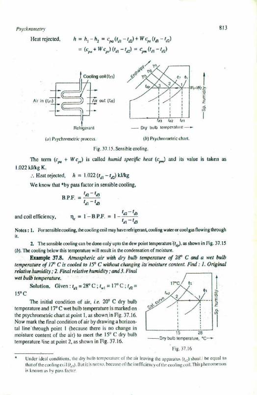


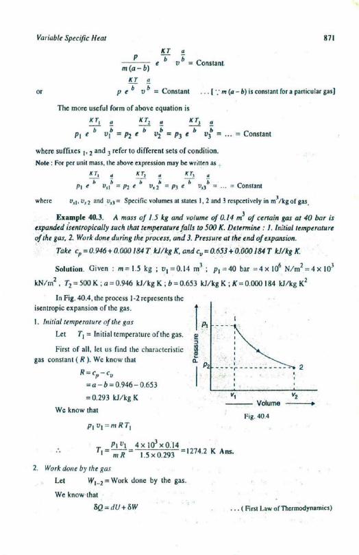


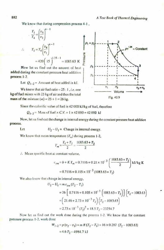


![INDEX [shodh.inflibnet.ac.in:8080]](https://static.documents.pub/doc/80x56/617729fad5903d63bd1810b7/index-shodh-.jpg)


