Updated 09/23/11 PT SERIES PTD SERIES PTD-G SERIES PTD-H SERIES SD SERIES SD-G SERIES SD-H SERIES Service & Installation Instructions Keep this booklet for Future Reference For Additional Copies Please Contact: Hillphoenix Barker Specialty Products 703 Franklin Street P.O. Box 478 Keosauqua, Iowa 52565 Tel: 319/ 293-3777 Fax: 319/ 293-3776 Or Visit: www.hillphoenix.com
Transcript
Updated 09/23/11
PT SERIESPTD SERIESPTD-G SERIESPTD-H SERIESSD SERIESSD-G SERIESSD-H SERIES
Service & Installation InstructionsKeep this booklet for Future Reference
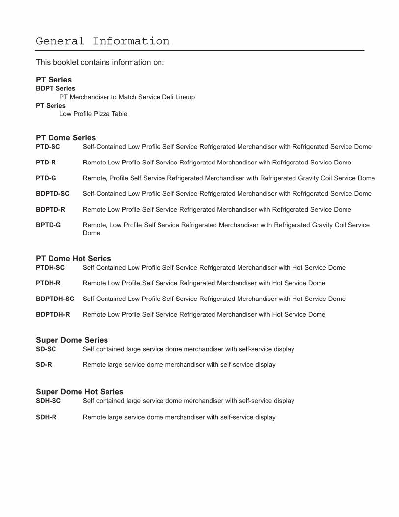
PT Dome SeriesPTD-SC Self-Contained Low Profile Self Service Refrigerated Merchandiser with Refrigerated Service Dome
PTD-R Remote Low Profile Self Service Refrigerated Merchandiser with Refrigerated Service Dome
PTD-G Remote, Profile Self Service Refrigerated Merchandiser with Refrigerated Gravity Coil Service Dome
BDPTD-SC Self-Contained Low Profile Self Service Refrigerated Merchandiser with Refrigerated Service Dome
BDPTD-R Remote Low Profile Self Service Refrigerated Merchandiser with Refrigerated Service Dome
BPTD-G Remote, Low Profile Self Service Refrigerated Merchandiser with Refrigerated Gravity Coil Service
Dome
PT Dome Hot SeriesPTDH-SC Self Contained Low Profile Self Service Refrigerated Merchandiser with Hot Service Dome
PTDH-R Remote Low Profile Self Service Refrigerated Merchandiser with Hot Service Dome
BDPTDH-SC Self Contained Low Profile Self Service Refrigerated Merchandiser with Hot Service Dome
BDPTDH-R Remote Low Profile Self Service Refrigerated Merchandiser with Hot Service Dome
Super Dome SeriesSD-SC Self contained large service dome merchandiser with self-service display
SD-R Remote large service dome merchandiser with self-service display
Super Dome Hot SeriesSDH-SC Self contained large service dome merchandiser with self-service display
SDH-R Remote large service dome merchandiser with self-service display
Shipping Information
IMPORTANT!FOR YOUR PROTECTION PLEASE READ AND OBSERVE THE FOLLOWING INSTRUCTIONS:
Transportation companies assume all liability from the time a shipment is received by them until the time it is
delivered to the consumer. Our liability ceases at the time of shipment.
All shipments leaving our plant have been carefully inspected. If a shipment arrives with the crating or packag-
ing damaged, have the carrier note the condition on the receipt. Check as soon as possible for concealed dam-
age.
If it is found that the shipment has been damaged in transit, please DO NOT return it to us, but notify and file a
claim with the carrier at once. FAILURE TO FOLLOW THIS PROCEDURE WILL RESULT IN REFUSAL BY
THE CARRIER TO HONOR ANY CLAIMS WITH A CONSEQUENT LOSS TO THE CONSUMER.
If a UPS shipment has been damaged, retain the damaged material and the carton and notify us at once. WE
will file a claim.
GOODS SHOULD NOT BE RETURNED FOR CREDIT UNLESS AUTHORIZED BY OUR SALES DEPART-
MENT.
The PT DOME Series conform to the following standards
The SUPER DOME Series conform to the following standards
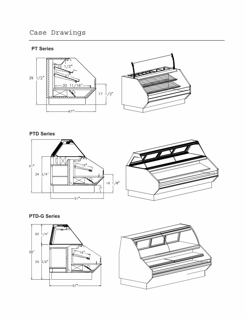
Case Drawings
PTD Series
PTD-G Series
PT Series
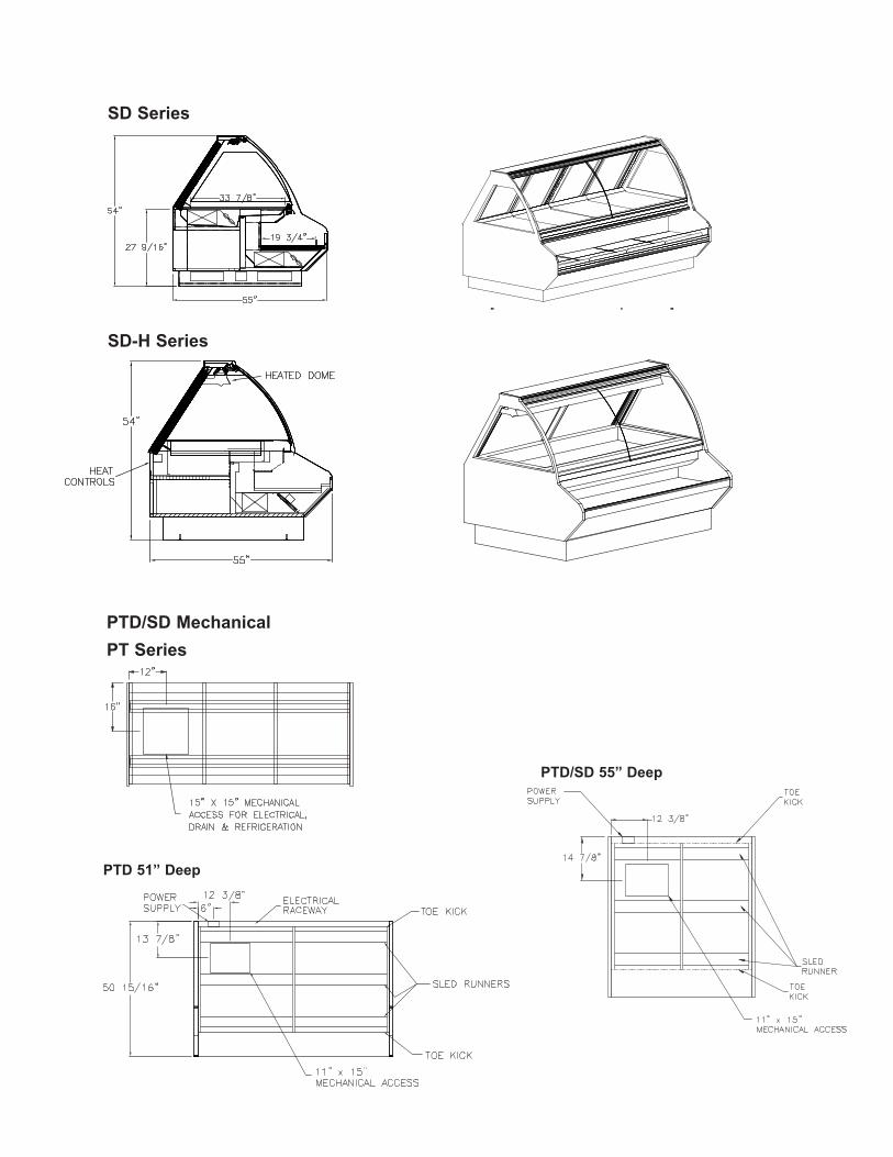
SD Series
SD-H Series
PTD/SD Mechanical
PTD 51” Deep
PTD/SD 55” Deep
PT Series
Installation Instructions
LocationThis refrigerated display case has been designed
for displaying and the storage of perishable food
product. It is engineered for air-conditioned stores
with a maximum ambient of 75° F and 55% relative
humidity.When selecting the location for placement
of this case, avoid the following conditions:
Excessive air movement• Doors• Air-conditioned vents• Other air sources
Excessive heat• Windows• Sun• Flood lamps 8 feet or less from the product• Other heat sources
NOTE: A 12" clearance is necessary for condenser
coil to run correctly. Do not block.
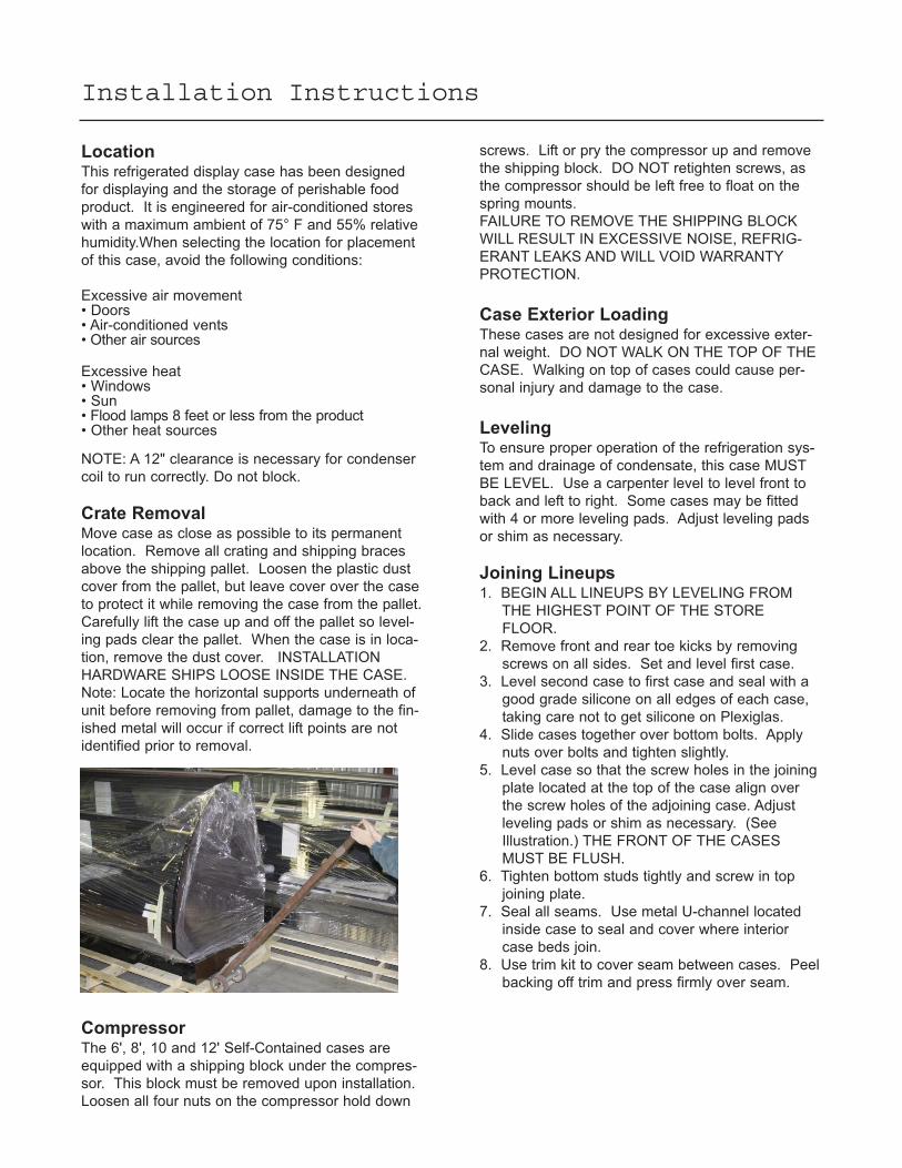
Crate RemovalMove case as close as possible to its permanent
location. Remove all crating and shipping braces
above the shipping pallet. Loosen the plastic dust
cover from the pallet, but leave cover over the case
to protect it while removing the case from the pallet.
Carefully lift the case up and off the pallet so level-
ing pads clear the pallet. When the case is in loca-
tion, remove the dust cover. INSTALLATION
HARDWARE SHIPS LOOSE INSIDE THE CASE.
Note: Locate the horizontal supports underneath of
unit before removing from pallet, damage to the fin-
ished metal will occur if correct lift points are not
identified prior to removal.
screws. Lift or pry the compressor up and remove
the shipping block. DO NOT retighten screws, as
the compressor should be left free to float on the
spring mounts.
FAILURE TO REMOVE THE SHIPPING BLOCK
WILL RESULT IN EXCESSIVE NOISE, REFRIG-
ERANT LEAKS AND WILL VOID WARRANTY
PROTECTION.
Case Exterior LoadingThese cases are not designed for excessive exter-
nal weight. DO NOT WALK ON THE TOP OF THE
CASE. Walking on top of cases could cause per-
sonal injury and damage to the case.
LevelingTo ensure proper operation of the refrigeration sys-
tem and drainage of condensate, this case MUST
BE LEVEL. Use a carpenter level to level front to
back and left to right. Some cases may be fitted
with 4 or more leveling pads. Adjust leveling pads
or shim as necessary.
Joining Lineups1. BEGIN ALL LINEUPS BY LEVELING FROM
THE HIGHEST POINT OF THE STORE
FLOOR.
2. Remove front and rear toe kicks by removing
screws on all sides. Set and level first case.
3. Level second case to first case and seal with a
good grade silicone on all edges of each case,
taking care not to get silicone on Plexiglas.
4. Slide cases together over bottom bolts. Apply
nuts over bolts and tighten slightly.
5. Level case so that the screw holes in the joining
plate located at the top of the case align over
the screw holes of the adjoining case. Adjust
leveling pads or shim as necessary. (See
Illustration.) THE FRONT OF THE CASES
MUST BE FLUSH.
6. Tighten bottom studs tightly and screw in top
joining plate.
7. Seal all seams. Use metal U-channel located
inside case to seal and cover where interior
case beds join.
8. Use trim kit to cover seam between cases. Peel
backing off trim and press firmly over seam.
CompressorThe 6', 8', 10 and 12' Self-Contained cases are
equipped with a shipping block under the compres-
sor. This block must be removed upon installation.
Loosen all four nuts on the compressor hold down
DoorsRear load doors are shipped inside the case. Push
top of doors all the way into top door tracks. Push
bottom of door over bottom door tracks and lower
over tracks. Doors are labeled inside and outside
for easy installation.
Optional ShelvingAll shelves are adjustable in 1" increments and may
be positioned flat or angled. Shelves are to be
installed with the smallest depth on top and larger
on the bottom for proper air flow. Shelf brackets can
be removed by lifting shelf up about 30° and pulling
straight out. Reposition brackets as desired. All
cases with shelf lights are equipped with an inter-
locking plug system. FOR SHELF LIGHTS TO
WORK, PLUGS MUST BE FULLY ENGAGED.
Wire Shelving
1. Wire shelving is shipped in the case and
secured for shipping with plastic ties.
2. Remove plastic shipping straps before
repositioning.
3. Wire shelves may be used in an angled or flat
position. (See Illustration on next page.)
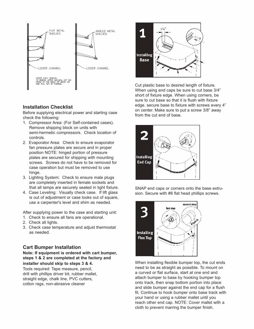
Metal Shelving
1. Metal shelving over 12" in depth is shipped
separately. Remove from crate and install as
shown below. If metal shelving is 12" in depth
or less shelving is shipped inside case.
2. Remove plastic shipping straps on shelves
shipped inside case before repositioning.
3. Metal shelves may be flat or angled.
Drain, Electrical and Refrigeration
ConnectionsNote: Barker remote units are shipped with a
dry nitrogen charge of approximately 10 lbs.
pressure in the evaporator coil. During installa-
tion if nitrogen charge is not present, leak
check accordingly.
1. 4', 6', 8' and 10' cases contain one condensate
drain. 12' cases contain two condensate drains.
Connect drains to existing floor drains. Provide
as much downhill slope as possible and avoid
long runs of drain lines. Do not install conden-
sate drains in contact with non-insulated suction
lines in order to prevent condensate from freez-
ing. (See mechanical plans and table for drain locations.) NOTE: P Traps must be installed
prior to floor drain.
2. Electrical connections are made through the
power supply box in the electrical raceway of
each case, which can be accessed from the
front toe kick. Voltage requirements and
component amperes can be found in the
electrical section of this manual, but always
check the data tag located on the exterior of the
case.
3. Refrigeration connections will be made through
the refrigeration stub up (see mechanical plans for each case). See refrigeration information
section for case loads and recommended
settings. Refrigeration lines may be headed
together for all cases in a line up, if desired, by
running lines through the refrigeration access
hole in each end or through access in the
bottom (toe kick area) of the case. Seal all
access holes to prevent recirculation.
For proper refrigeration performance, PRODUCT
MUST NOT BE PLACED IN A POSITION WHERE
IT MAY AFFECT THE AIR CURTAIN. Air discharge
and return air vents must remain unobstructed.
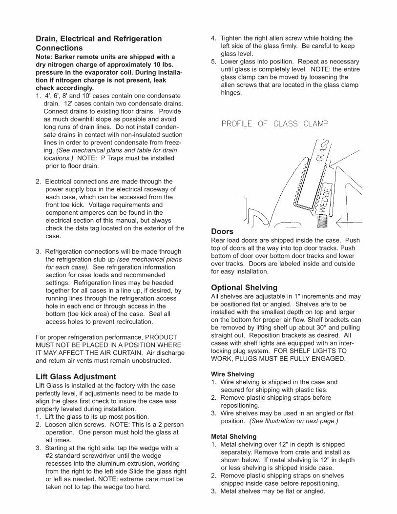
Lift Glass AdjustmentLift Glass is installed at the factory with the case
perfectly level, if adjustments need to be made to
align the glass first check to insure the case was
properly leveled during installation.
1. Lift the glass to its up most position.
2. Loosen allen screws. NOTE: This is a 2 person
operation. One person must hold the glass at
all times.
3. Starting at the right side, tap the wedge with a
#2 standard screwdriver until the wedge
recesses into the aluminum extrusion, working
from the right to the left side Slide the glass right
or left as needed. NOTE: extreme care must be
taken not to tap the wedge too hard.
4. Tighten the right allen screw while holding the
left side of the glass firmly. Be careful to keep
glass level.
5. Lower glass into position. Repeat as necessary
until glass is completely level. NOTE: the entire
glass clamp can be moved by loosening the
allen screws that are located in the glass clamp
hinges.
Installation ChecklistBefore supplying electrical power and starting case
check the following:
1. Compressor Area: (For Self-contained cases).
Remove shipping block on units with
semi-hermetic compressors. Check location of
controls.
2. Evaporator Area: Check to ensure evaporator
fan pressure plates are secure and in proper
position NOTE: hinged portion of pressure
plates are secured for shipping with mounting
screws. Screws do not have to be removed for
case operation but must be removed to use
hinge.
3. Lighting System: Check to ensure male plugs
are completely inserted in female sockets and
that all lamps are securely seated in light fixture.
4. Case Leveling: Visually check case. If lift glass
is out of adjustment or case looks out of square,
use a carpenter's level and shim as needed.
After supplying power to the case and starting unit:
1. Check to ensure all fans are operational.
2. Check all lights.
3. Check case temperature and adjust thermostat
as needed.
Cart Bumper InstallationNote: If equipment is ordered with cart bumper,
steps 1 & 2 are completed at the factory and
installer should skip to steps 3 & 4.
Tools required: Tape measure, pencil,
drill with phillips driver bit, rubber mallet,
straight edge, chalk line, PVC cutters,
cotton rags, non-abrasive cleaner
Cut plastic base to desired length of fixture.
When using end caps be sure to cut base 3/4”
short of fixture edge. When using corners, be
sure to cut base so that it is flush with fixture
edge. secure base to fixture with screws every 4”
on center. Make sure to put a screw 3/8” away
from the cut end of base.
SNAP end caps or corners onto the base extru-
sion. Secure with #8 flat head phillips screws.
When installing flexible bumper top, the cut ends
need to be as straight as possible. To mount on
a curved or flat surface, start at one end and
attach bumper to base by hooking bumper top
onto track, then snap bottom portion into place
and slide bumper against the end cap for a flush
fit. Continue to hook bumper onto base track with
your hand or using a rubber mallet until you
reach other end cap. NOTE: Cover mallet with a
cloth to prevent marring the bumper finish.
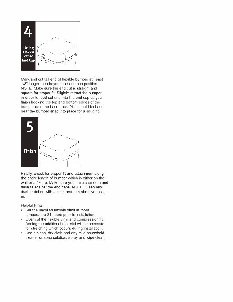
Mark and cut tail end of flexible bumper at least
1/8” longer then beyond the end cap position.
NOTE: Make sure the end cut is straight and
square for proper fit. Slightly retract the bumper
in order to feed cut end into the end cap as you
finish hooking the top and bottom edges of the
bumper onto the base track. You should feel and
hear the bumper snap into place for a snug fit.
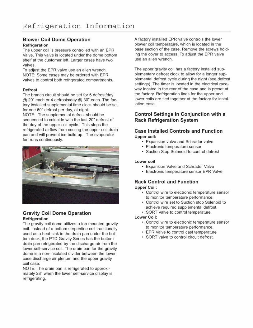
Finally, check for proper fit and attachment along
the entire length of bumper which is either on the
wall or a fixture. Make sure you have a smooth and
flush fit against the end caps. NOTE: Clean any
dust or debris with a cloth and non abrasive clean-
er.
Helpful Hints:
• Set the uncoiled flexible vinyl at room
temperature 24 hours prior to installation.
• Over cut the flexible vinyl and compression fit.
Adding the additional material will compensate
for stretching which occurs during installation.
• Use a clean, dry cloth and any mild household
cleaner or soap solution; spray and wipe clean
Refrigeration Information
Blower Coil Dome OperationRefrigeration
The upper coil is pressure controlled with an EPR
Valve. This valve is located under the dome bottom
shelf at the customer left. Larger cases have two
valves.
To adjust the EPR valve use an allen wrench.
NOTE: Some cases may be ordered with EPR
valves to control both refrigerated compartments.
Defrost
The branch circuit should be set for 6 defrost/day
@ 20" each or 4 defrosts/day @ 30" each. The fac-
tory installed supplemental time clock should be set
for one 60" defrost per day, at night.
NOTE: The supplemental defrost should be
sequenced to coincide with the last 20" defrost of
the day of the upper coil cycle. This stops the
refrigerated airflow from cooling the upper coil drain
pan and will prevent ice build up. The evaporator
fan runs continuously.
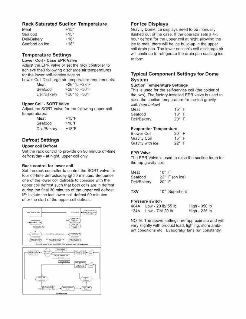
Gravity Coil Dome OperationRefrigeration
The gravity coil dome utilizes a top-mounted gravity
coil. Instead of a bottom serpentine coil traditionally
used as a heat sink in the drain pan under the bot-
tom deck, the PTD Gravity Series has the bottom
drain pan refrigerated by the discharge air from the
lower self-service coil. The drain pan for the gravity
dome is a non-insulated divider between the lower
case discharge air plenum and the upper gravity
coil case.
NOTE: The drain pan is refrigerated to approxi-
mately 28° when the lower self-service display is
refrigerating.
A factory installed EPR valve controls the lower
blower coil temperature, which is located in the
base section of the case. Remove the screws hold-
ing the cover to access. To adjust the EPR valve
use an allen wrench.
The upper gravity coil has a factory installed sup-
plementary defrost clock to allow for a longer sup-
plemental defrost cycle during the night (see defrost
settings). The timer is located in the electrical race-
way located in the rear of the case and is preset at
the factory. Refrigeration lines for the upper and
lower coils are tied together at the factory for instal-
lation ease.
Control Settings in Conjunction with a
Rack Refrigeration System
Case Installed Controls and FunctionUpper coil:
• Expansion valve and Schrader valve
• Electronic temperature sensor
• Suction Stop Solenoid to control defrost
Lower coil
• Expansion Valve and Schrader Valve
• Electronic temperature sensor EPR Valve
Rack Control and FunctionUpper Coil:
• Control wire to electronic temperature sensor
to monitor temperature performance.
• Control wire set to Suction stop Solenoid to
achieve required supplemental defrost.
• SORT Valve to control temperature
Lower Coil:
• Control wire to electronic temperature sensor
to monitor temperature performance.
• EPR Valve to control cast temperature
• SORT valve to control circuit defrost.
For Ice DisplaysGravity Dome ice displays need to be manually
flushed out of the case. If the operator sets a 4-5
hour defrost for the upper coil at night allowing the
ice to melt, there will be ice build-up in the upper
coil drain pan. The lower section's coil discharge air
will continue to refrigerate the drain pan causing ice
to form.
Rack Saturated Suction TemperatureMeat +15°
Seafood +15°
Deli/Bakery +18°
Seafood on ice +18°
Temperature SettingsLower Coil - Case EPR Valve
Adjust the EPR valve or set the rack controller to
achieve the3 following discharge air temperatures
for the lower self-service section
Lower Coil Discharge air temperature requirements:
Meat +26° to +28°F
Seafood +28° to +30°F
Deli/Bakery +28° to +30°F
Upper Coil - SORT Valve
Adjust the SORT Valve for the following upper coil
temperatures:
Meat +15°F
Seafood +18°F
Deli/Bakery +18°F
Defrost Settings
Upper coil Defrost
Set the rack control to provide on 90 minute off-time
defrost/day - at night, upper coil only.
Rack control for lower coil
Set the rack controller to control the SORT valve for
four off-time defrosts/day @ 30 minutes. Sequence
one of the lower coil defrosts to coincide with the
upper coil defrost such that both coils are in defrost
during the final 30 minutes of the upper coil defrost.
IE: Initiate the last lower coil defrost 60 minutes
after the start of the upper coil defrost.
Typical Component Settings for Dome
SystemSuction Temperature Settings
This is used for the self-service coil (the colder of
the two). The factory-installed EPR valve is used to
raise the suction temperature for the top gravity
coil. (see below)Meat 15° F
Seafood 18° F
Deli/Bakery 20° F
Evaporator Temperature
Blower Coil 20° F
Gravity Coil 15° F
Gravity with ice 22° F
EPR Valve
The EPR Valve is used to raise the suction temp for
the top gravity coil.
Meat 18° F
Seafood 22° F (on ice)
Deli/Bakery 20° F
TXV 10° Superheat
Pressure switch
404A Low - 20 lb/ 55 lb High - 350 lb
134A Low - 7lb/ 20 lb High - 225 lb
NOTE: The above settings are approximate and will
vary slightly with product load, lighting, store ambi-
ent conditions etc. Evaporator fans run constantly.
Programming Steps for the ETC, Electronic
Temperature Control
STEP 1. Press the set key once to access the
Fahrenheit/Celsius mode. The display will
display either F degrees Fahrenheit or C
for degrees Celsius.
Press the up arrow or the down arrow so
the display indicates F.
STEP 2. Press the set key again to gain access to
the set point. The LCD will display the
current Set point and the S1 will be
blinking. Press the up arrow to increase
or the down arrow to decrease the
temperature setting.
STEP 3. Press the set key again to gain access to
the differential. The LCD will display the
current differential and the DIF 1 will be
blinking. This should be set at 6 degrees.
STEP 4. Press the set key again to gain access to
the cooling or heating mode. The LCD
will display the current mode. Press
either the up arrow or the down arrow to
set the display in the C1, cooling mode
STEP 5. Press the set key once more and the
programming is complete.
STEP 6.
1.
2.
3.
4.
DISPLAY
INDICATION
F or C
S1 (blinking)
DIF (blinking)
C1/H1
DESCRIPTION
Fahrenheit or Celsius Scale
Set point Temperature
Differential Temperature
Cooling or Heating Mode
Lower Case OperationRefrigeration
The refrigeration in the lower part of this case is
thermostatically controlled. The case refrigerates
until the cut out point on the thermostat is reached.
The thermostat opens, cutting power to the liquid
line solenoid. The compressor continues to run, the
system pumps down causing the pressure switch to
open, cutting power to the compressor. If the case
is equipped with a refrigerated rear storage area, a
separate but identical refrigeration system is pres-
ent. NOTE: Some cases may be ordered with EPR
valves to control both upper and lower refrigerated
compartments.
Defrost
This case is equipped with an off cycle defrost sys-
tem. The timer cuts the power to the liquid solenoid.
The unit stays in off cycle defrost until the defrost
timer re-energizes the liquid solenoid.
NOTE: The evaporator fan runs continuously.
Typical Component Setting For Lower
and Rear Storage SystemsThermostat cut out
26-28º 6º differential
Defrost termination thermostat: 40-42º
TXV: 10º Superheat
Pressure switch
404A Low - 20lb/ 55lb High - 350 lb
134A Low - 7lb/ 20lb High - 225lb
Note: The above settings are approximate and will
vary slightly with product load, lighting, store ambi-
ent conditions etc. Evaporator fans run constantly.
Electronic ThermostatThe electronic thermostat is located at the rear of
the case in the electronic raceway. The thermostat
is equipped with a liquid crystal display providing a
constant readout of the sensed temperature.
NOTE: The LCD display will be blank during
defrost. A touch keypad that allows the users to
select the set point temperature, differential and the
heating /cooling modes.
WARNING!USE ONLY DOWFROST, PREMIXED 35% INHIBITED PROPY -LENE GLYCOL. USE OF ANY OTHER GLYCOL WILL VOID
THE MANUFACTURER WARRANTY.
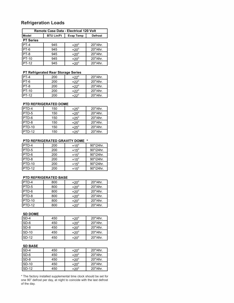
Refrigeration Loads
Model BTU Lin/Ft Evap Temp Defrost
PT Series
PT-4 945 +20o 20"/4hr.
PT-6 945 +20o 20"/4hr.
PT-8 945 +20o 20"/4hr.
PT-10 945 +20o 20"/4hr.
PT-12 945 +20o 20"/4hr.
PT Refrigerated Rear Storage Series
PT-4 200 +22o 20"/4hr.
PT-6 200 +22o 20"/4hr.
PT-8 200 +22o 20"/4hr.
PT-10 200 +22o 20"/4hr.
PT-12 200 +22o 20"/4hr.
PTD REFRIGERATED DOME
PTD-4 150 +25o 20"/4hr.
PTD-5 150 +25o 20"/4hr.
PTD-6 150 +25o 20"/4hr.
PTD-8 150 +25o 20"/4hr.
PTD-10 150 +25o 20"/4hr.
PTD-12 150 +25o 20"/4hr.
PTD REFRIGERATED GRAVITY DOME
PTD-4 200 +15o 90"/24hr.
PTD-5 200 +15o 90"/24hr.
PTD-6 200 +15o 90"/24hr.
PTD-8 200 +15o 90"/24hr.
PTD-10 200 +15o 90"/24hr.
PTD-12 200 +15o 90"/24hr.
PTD REFRIGERATED BASE
PTD-4 800 +20o 20"/4hr.
PTD-5 800 +20o 20"/4hr.
PTD-6 800 +20o 20"/4hr.
PTD-8 800 +20o 20"/4hr.
PTD-10 800 +20o 20"/4hr.
PTD-12 800 +20o 20"/4hr.
SD DOME
SD-4 450 +20o 20"/4hr.
SD-6 450 +20o 20"/4hr.
SD-8 450 +20o 20"/4hr.
SD-10 450 +20o 20"/4hr.
SD-12 450 +20o 20"/4hr.
SD BASE
SD-4 450 +20o 20"/4hr.
SD-6 450 +20o 20"/4hr.
SD-8 450 +20o 20"/4hr.
SD-10 450 +20o 20"/4hr.
SD-12 450 +20o 20"/4hr.
Remote Case Data - Electrical 120 Volt
* The factory installed supplemental time clock should be set for
one 90” defrost per day, at night to coincide with the last defrost
of the day.
*
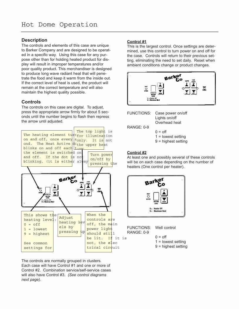
Hot Dome Operation
DescriptionThe controls and elements of this case are unique
to Barker Company and are designed to be operat-
ed in a specific way. Using this case for any pur-
pose other than for holding heated product for dis-
play will result in improper temperatures and/or
poor quality product. This merchandiser is designed
to produce long wave radiant heat that will pene-
trate the food and keep it warm from the inside out.
If the correct level of heat is used, the product will
remain at the correct temperature and will also
maintain the highest quality possible.
ControlsThe controls on this case are digital. To adjust,
press the appropriate arrow firmly for about 5 sec-
onds until the number begins to flash then repress
the arrow until adjusted.
The heating element turnson and off, once every sec-ond. The Heat Active dotblinks on and off each timethe element is switched onand off. If the dot is notblinking, (it is either always
The top light isfor illuminationonly. It is notthe upper heat
Turn poweron/off bypressing the
This shows theheating level:0 = off1 = lowest9 = highest
See commonsettings for
Adjustheating lev-els bypressing up
When thecontrols areoff, the mainpower lightshould stillbe lit. If it isnot, the elec-trical circuit
The controls are normally grouped in clusters.
Each case will have Control #1 and one or more of
Control #2. Combination service/self-service cases
will also have Control #3. (See control diagramsnext page).
Control #1
This is the largest control. Once settings are deter-
mined, use this control to turn power on and off for
the case. Controls will return to their previous set-
ting, eliminating the need to set daily. Reset when
ambient conditions change or product changes.
FUNCTIONS: Case power on/off
Lights on/off
Overhead heat
RANGE: 0-9
0 = off
1 = lowest setting
9 = highest setting
Control #2
At least one and possibly several of these controls
will be on each case depending on the number of
heaters (One control per heater).
FUNCTIONS: Well control
RANGE: 0-9
0 = off
1 = lowest setting
9 = highest setting
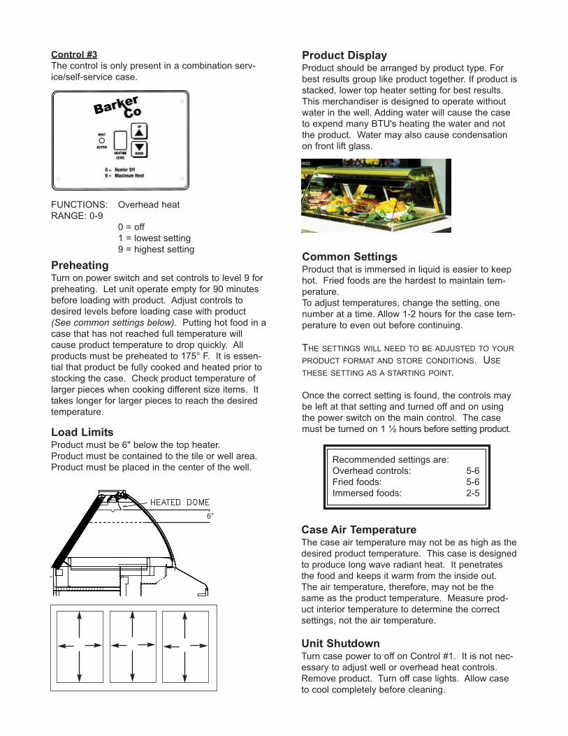
Control #3
The control is only present in a combination serv-
ice/self-service case.
FUNCTIONS: Overhead heat
RANGE: 0-9
0 = off
1 = lowest setting
9 = highest setting
PreheatingTurn on power switch and set controls to level 9 for
preheating. Let unit operate empty for 90 minutes
before loading with product. Adjust controls to
desired levels before loading case with product
(See common settings below). Putting hot food in a
case that has not reached full temperature will
cause product temperature to drop quickly. All
products must be preheated to 175° F. It is essen-
tial that product be fully cooked and heated prior to
stocking the case. Check product temperature of
larger pieces when cooking different size items. It
takes longer for larger pieces to reach the desired
temperature.
Load LimitsProduct must be 6" below the top heater.
Product must be contained to the tile or well area.
Product must be placed in the center of the well.
Product DisplayProduct should be arranged by product type. For
best results group like product together. If product is
stacked, lower top heater setting for best results.
This merchandiser is designed to operate without
water in the well. Adding water will cause the case
to expend many BTU's heating the water and not
the product. Water may also cause condensation
on front lift glass.
Common SettingsProduct that is immersed in liquid is easier to keep
hot. Fried foods are the hardest to maintain tem-
perature.
To adjust temperatures, change the setting, one
number at a time. Allow 1-2 hours for the case tem-
perature to even out before continuing.
THE SETTINGS WILL NEED TO BE ADJUSTED TO YOUR
PRODUCT FORMAT AND STORE CONDITIONS. USE
THESE SETTING AS A STARTING POINT.
Once the correct setting is found, the controls may
be left at that setting and turned off and on using
the power switch on the main control. The case
must be turned on 1 ½ hours before setting product.
Recommended settings are:
Overhead controls: 5-6
Fried foods: 5-6
Immersed foods: 2-5
Case Air TemperatureThe case air temperature may not be as high as the
desired product temperature. This case is designed
to produce long wave radiant heat. It penetrates
the food and keeps it warm from the inside out.
The air temperature, therefore, may not be the
same as the product temperature. Measure prod-
uct interior temperature to determine the correct
settings, not the air temperature.
Unit ShutdownTurn case power to off on Control #1. It is not nec-
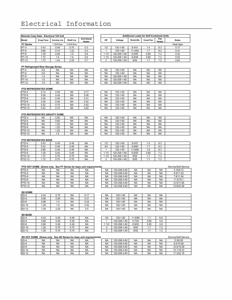
SD-10 1.29 0.75 0.75 NA 2 120-208-1-60 9/55 1.7 7.2
SD-12 1.29 0.75 0.75 NA 2 120-208-1-60 9/55 1.7 7.2
SD HOT DOME (Dome only. See SD Series for base unit requirements) Service/Self-Service
SD-4 NA NA NA NA NA 120-208-3-60 NA NA NA 5.3/6.95
SD-6 NA NA NA NA NA 120-208-3-60 NA NA NA 8.5/10.96
SD-8 NA NA NA NA NA 120-208-3-60 NA NA NA 12.0/15.29
SD-10 NA NA NA NA NA 120-208-3-60 NA NA NA 14.1/18.23
SD-12 NA NA NA NA NA 120-208-3-60 NA NA NA 17.3/22.18
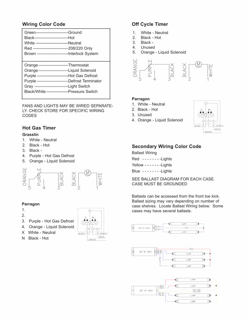
Ballasts can be accessed from the front toe kick.
Ballast sizing may vary depending on number of
case shelves. Locate Ballast Wiring below. Some
cases may have several ballasts.
Hot Gas Timer
Wiring Color Code Off Cycle Timer
Parragon
1. White - Neutral
2. Black - Hot
3. Unused
4. Orange - Liquid Solenoid
Grasslin
1. White - Neutral
2. Black - Hot
3. Black -
4. Purple - Hot Gas Defrost
5. Orange - Liquid Solenoid
Parragon
1.
2.
3. Purple - Hot Gas Defrost
4. Orange - Liquid Solenoid
X White - Neutral
N Black - Hot
Secondary Wiring Color Code
Ballast Wiring
Red - - - - - - - -Lights
Yellow - - - - - - -Lights
Blue - - - - - - - -Lights
SEE BALLAST DIAGRAM FOR EACH CASE.
CASE MUST BE GROUNDED
FANS AND LIGHTS MAY BE WIRED SEPARATE-
LY. CHECK STORE FOR SPECIFIC WIRING
CODES
1. White - Neutral
2. Black - Hot
3. Black -
4. Unused
5. Orange - Liquid Solenoid
Green------------------------Ground
Black-------------------------Hot
White ------------------------Neutral
Red --------------------------208/220 Only
Brown -----------------------Interlock System
Orange ----------------------Thermostat
Orange ----------------------Liquid Solenoid
Purple -----------------------Hot Gas Defrost
Purple -----------------------Defrost Terminator
Gray -------------------------Light Switch
Black/White ----------------Pressure Switch
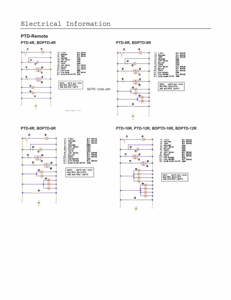
NOTE: Units with
Electrical Information
PTD-Remote
PTD-4R, BDPTD-4R
PTD-8R, BDPTD-8R
PTD-6R, BDPTD-6R
PTD-10R, PTD-12R, BDPTD-10R, BDPTD-12R
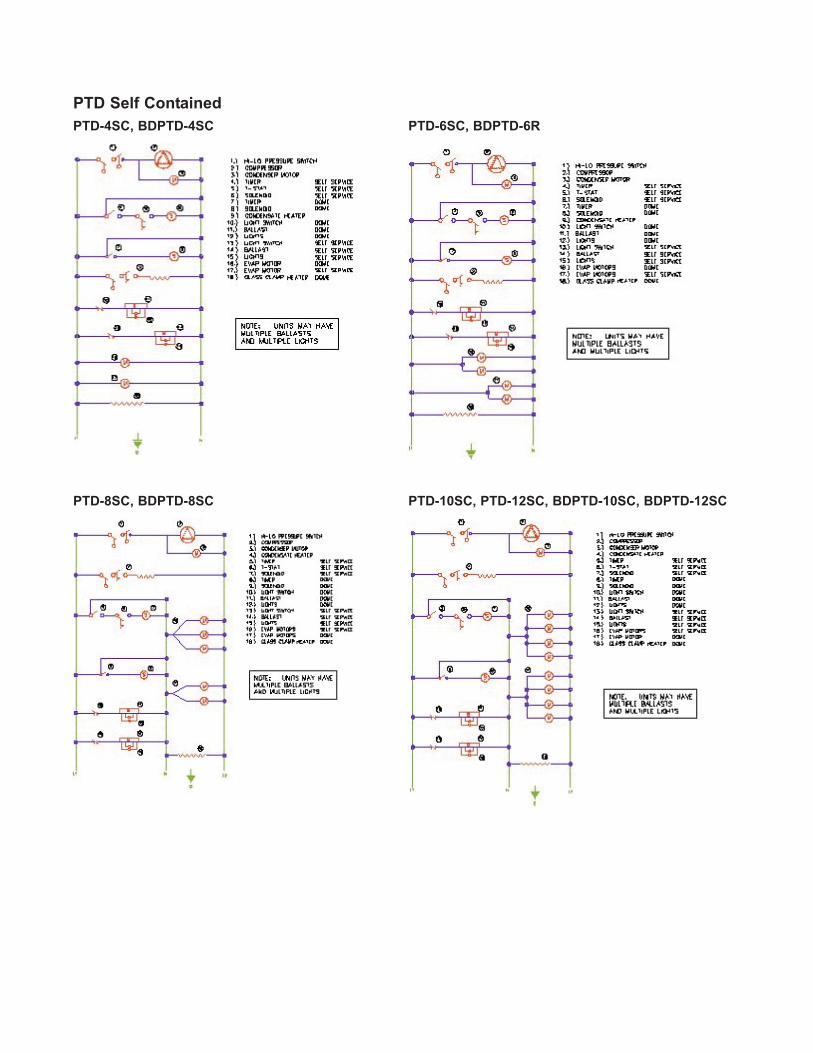
PTD Self Contained
PTD-4SC, BDPTD-4SC
PTD-8SC, BDPTD-8SC
PTD-6SC, BDPTD-6R
PTD-10SC, PTD-12SC, BDPTD-10SC, BDPTD-12SC
Maintenance Information
Cleaning Lower Self-Service Case &
Refrigerated Dome.Case Exterior
Clean surfaces frequently with warm water and mild
detergent.
DO NOT use strong alkali solutions, steel wool, or
abrasive cleanser. Be careful of any electrical out-
lets located on the exterior of the case.
Case Interior
All shelving, lower deck and dome deck can be
removed for cleaning (See installation instructionsfor removing and setting shelving). Check to make
sure the case drain(s) are not clogged. Clean interi-
or with warm water and a mild detergent. A sanitiz-
er should be used after washing to eliminate bacte-
ria. Rinse thoroughly being careful not to flood
drain system. Avoid spraying water directly into
electrical connections. DO NOT USE A HIGH
PRESSURE WATER HOSE. MAKE SURE FANS
AND LIGHTS ARE SHUT OFF WHEN CLEANING
THE INTERIOR OF THE CASE
Non-Glare Glass
Non-glare glass surfaces are coated to reduce the
glare from lighting. Care must be taken not to
scratch the coating. Use the following products only.
Cleaning Cloths
Scotch-Brite® High Performance Cloth - manu-
factured by 3M® and available in most grocery
stores under the name Scotch-Brite® Microfiber
Cleaning Cloth in a 12" x14" size. This cloth is
washable and may be reused as long as it remains
clean.
Spontex® Microfibre Cleaning Cloth - distributed
by Spontex® and available in most grocery stores
under the same name in a 15.75" x 12" size. This
cloth is washable and may be reused as long as it
remains clean.
The cleaning cloths named above will normally
remove dust, grease, oil and fingerprints without the
need for cleaning fluids. A light spray of the clean-
ing fluids listed below will reduce the time required
for cleaning.
Cleaning Fluid - for more difficult cleaning jobs,
these products are recommended:
Windex® - standard product only (extra-strength or
specialty products may not be suitable)
Glass-Plus® - standard product only (extra-
strength or specialty products may not be suitable)
Warm Water
DO NOT USE the following types of materials for
cleaning glass with anti-reflective coatings.
Coarse Paper Towels
Scouring Pads or Powders
Steel wool or Steel Fiber Materials
Blades
Acidic or highly Alkaline detergents
Fluorine based detergents
Plexiglas Cleaning
Use Novus® 1 and Novus® 2 to clean. Use
Brillianize® to polish. Contact factory to order. Do
not use strong alkali solutions, steel wool, or abra-
sive cleanser.
Evaporator Coil
Clean as needed.
Condenser Coil
Failure to clean coils will void warranty. Clean con-
denser coil every three months or as needed with a
whisk broom or vacuum. Disconnect power when
servicing. Fins on condenser coil are sharp!
Condensate Heater
Add one teaspoon of scale remover or white vine-
gar to condensate heater pan once every three
months or as needed. Heater is designed for 75º
and 50% relative humidity. The condensate pan
may overflow if design limits are exceeded.
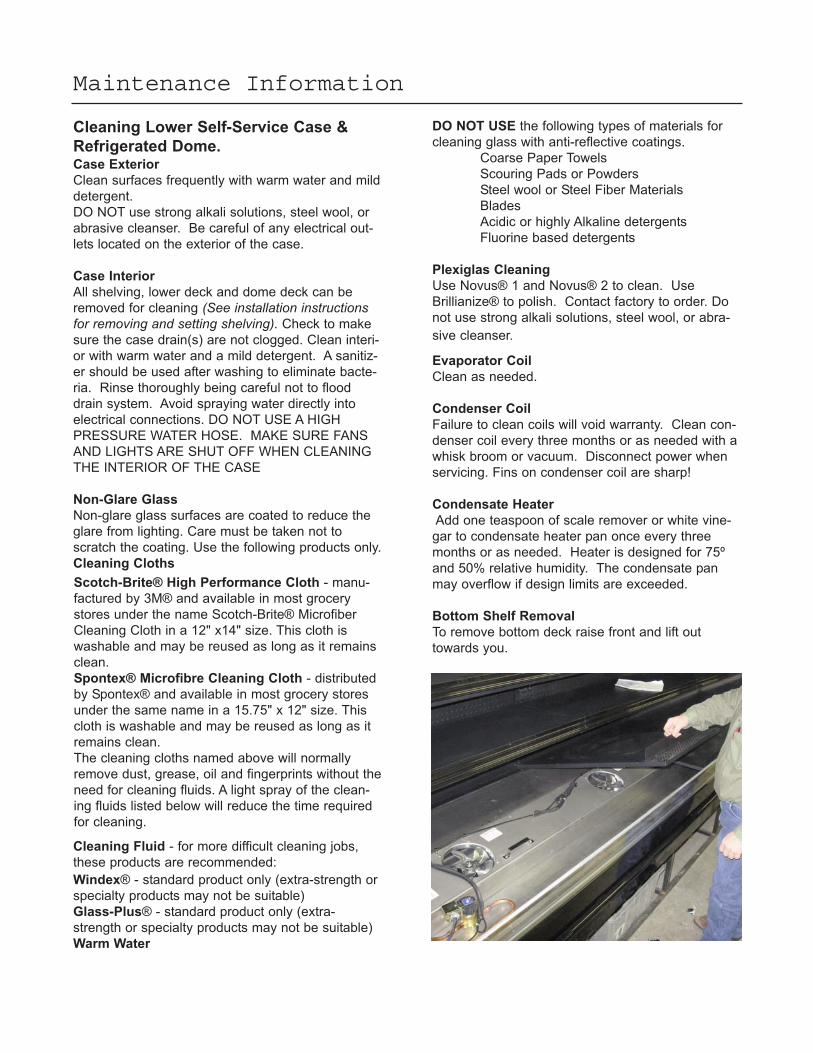
Bottom Shelf Removal
To remove bottom deck raise front and lift out
towards you.
Hot Dome CleaningUnit should be thoroughly cleaned at the end of
each day.
1. The unit must be cool and all power turned off.
NOTE: Unit may have more than one power supply.
2. Remove any food or residue.
3. Use mild soap and/or sanitizer to clean interior
and exterior.
4. Wipe dry with soft cloth.
5. Keep doors open until completely dry.
6. Never use alkali or abrasive cleaners.
7. Never steam clean.
8. Avoid excessive amounts of water.
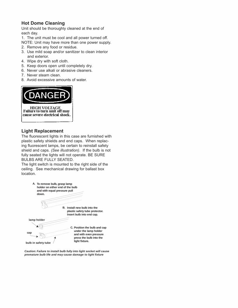
Light ReplacementThe fluorescent lights in this case are furnished with
plastic safety shields and end caps. When replac-
ing fluorescent lamps, be certain to reinstall safety
shield and caps. (See illustration). If the bulb is not
fully seated the lights will not operate. BE SURE
BULBS ARE FULLY SEATED.
The light switch is mounted to the right side of the
ceiling. See mechanical drawing for ballast box
location.
To remove bulb, grasp lamp holder on either end of the bulb and with equal pressure pull down.
Install new bulb into the plastic safety tube protector.Insert bulb into end cap.
Position the bulb and cap under the lamp holder and with even pressure press the bulb into the light fixture.
lamp holder
cap
Caution: Failure to install bulb fully into light socket will cause premature bulb life and may cause damage to light fixture
A.
B.
C.
bulb in safety tube
Service
WARNING!DISCONNECT THE ELECTRICAL POWER WHEN SERVICING OR REPLAC -
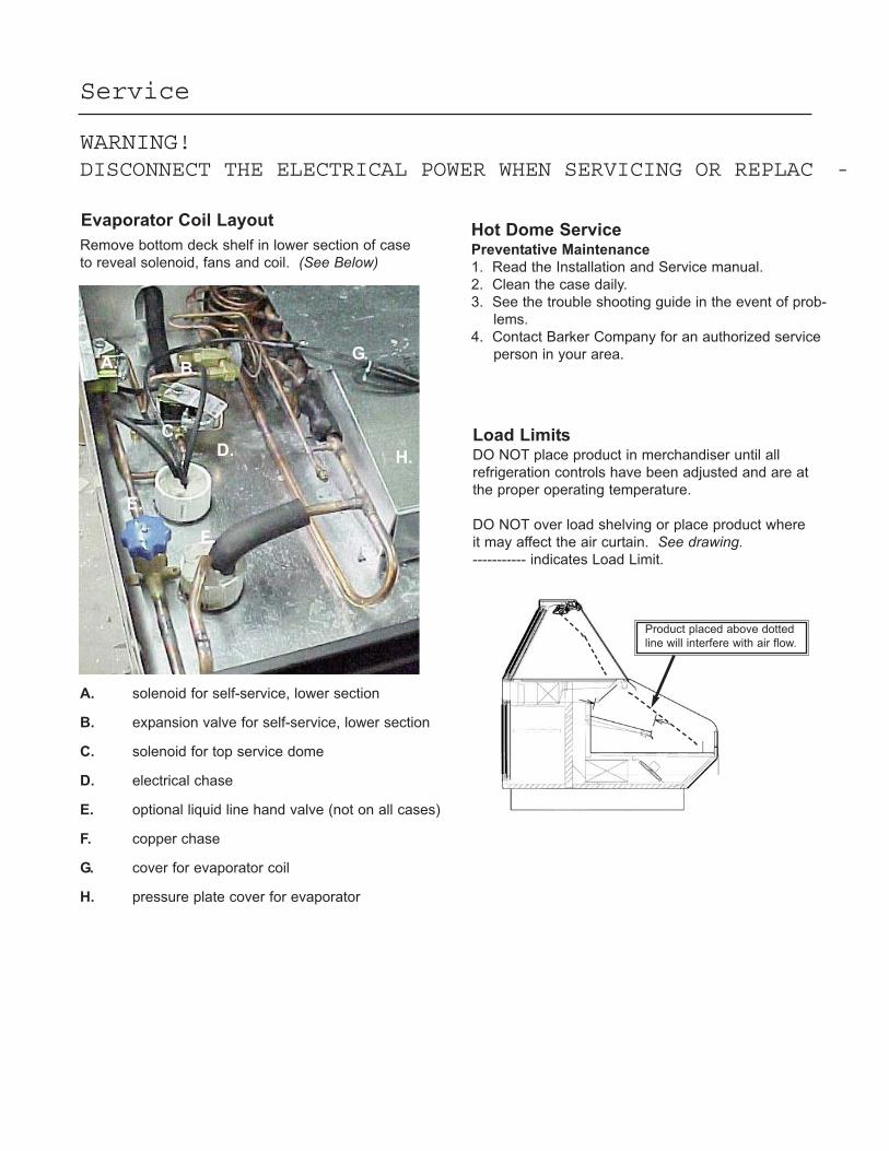
Remove bottom deck shelf in lower section of case
to reveal solenoid, fans and coil. (See Below)
A. solenoid for self-service, lower section
B. expansion valve for self-service, lower section
C. solenoid for top service dome
D. electrical chase
E. optional liquid line hand valve (not on all cases)
F. copper chase
G. cover for evaporator coil
H. pressure plate cover for evaporator
A. B.
C.D.
E.
F.
G.
H.
Hot Dome ServicePreventative Maintenance
1. Read the Installation and Service manual.
2. Clean the case daily.
3. See the trouble shooting guide in the event of prob-
lems.
4. Contact Barker Company for an authorized service
person in your area.
Load LimitsDO NOT place product in merchandiser until all
refrigeration controls have been adjusted and are at
the proper operating temperature.
DO NOT over load shelving or place product where
it may affect the air curtain. See drawing. ----------- indicates Load Limit.
Product placed above dotted
line will interfere with air flow.
Evaporator Coil Layout
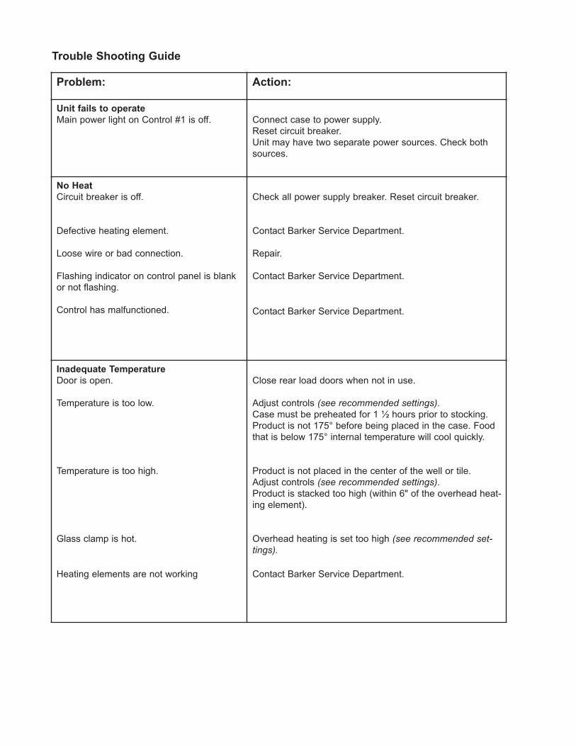
Problem: Action:
Unit fails to operate
Main power light on Control #1 is off. Connect case to power supply.
Reset circuit breaker.
Unit may have two separate power sources. Check both
sources.
No Heat
Circuit breaker is off.
Defective heating element.
Loose wire or bad connection.
Flashing indicator on control panel is blank
or not flashing.
Control has malfunctioned.
Check all power supply breaker. Reset circuit breaker.
Contact Barker Service Department.
Repair.
Contact Barker Service Department.
Contact Barker Service Department.
Inadequate Temperature
Door is open.
Temperature is too low.
Temperature is too high.
Glass clamp is hot.
Heating elements are not working
Close rear load doors when not in use.
Adjust controls (see recommended settings).Case must be preheated for 1 ½ hours prior to stocking.
Product is not 175° before being placed in the case. Food
that is below 175° internal temperature will cool quickly.
Product is not placed in the center of the well or tile.
Adjust controls (see recommended settings).Product is stacked too high (within 6" of the overhead heat-
ing element).
Overhead heating is set too high (see recommended set-tings).
Contact Barker Service Department.
Trouble Shooting Guide
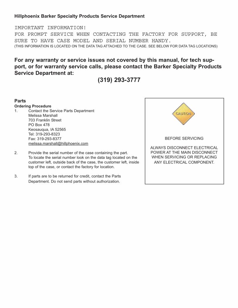
Hillphoenix Barker Specialty Products Service Department
IMPORTANT INFORMATION!FOR PROMPT SERVICE WHEN CONTACTING THE FACTORY FOR SUPPORT, BESURE TO HAVE CASE MODEL AND SERIAL NUMBER HANDY. (THIS INFORMATION IS LOCATED ON THE DATA TAG ATTACHED TO THE CASE. SEE BELOW FOR DATA TAG LOCATIONS)
For any warranty or service issues not covered by this manual, for tech sup-
port, or for warranty service calls, please contact the Barker Specialty Products
2. Provide the serial number of the case containing the part.
To locate the serial number look on the data tag located on the
customer left, outside back of the case, the customer left, inside
top of the case, or contact the factory for location.
3. If parts are to be returned for credit, contact the Parts
Department. Do not send parts without authorization.
BEFORE SERVICING
ALWAYS DISCONNECT ELECTRICAL
POWER AT THE MAIN DISCONNECT
WHEN SERVICING OR REPLACING
ANY ELECTRICAL COMPONENT.
WARRANTYHEREINAFTER REFERRED TO AS MANUFACTURER
FOURTEEN MONTH WARRANTY. MANUFACTURER’S PRODUCT IS WARRANTED TO FREE FROM DEFECTS IN MATERIAL AND WORKMANSHIP UNDER NORMAL USE AND MAINTENANCE FOR A PERIOD OF FOURTEEN MONTHS FROM THE DATE OF ORIGINAL SHIPMENT. A NEW OR REBUILT PART TO REPLACE ANY DEFECTIVE PART WILL BE PROVIDED WITHOUT CHARGE. PROVIDED THE DEFECTIVE PART IS RETURNED TO MANUFACTURER. THE REPLACEMENT PART ASSUMES THE UNUSED PORTION OF THE WARRANTY.
WARRANTY CLAIMS: All claims should include: the serial number of the cabinet, proof of purchase, date of installation, and all pertinent information supporting the existence of the alleged defect. Any action for breach of these warranty pro-visions must be commenced within one (1) year after that cause of action has accrued. All warranty service work must be pre-authorized by Barker Specialty Products (800-814-0446). Barker Specialty Products reserves the rights to designate the service provider, time in which labor is to be performed and specify amount of time per warranty problem.
This warranty does not include labor or other costs incurred for repairing, removing, installing, shipping, servicing or han-dling of either defective parts or replacement parts.
The fourteen month warranty shall not apply:
1. To any unit or any part thereof which has been subject to accident, alteration, negligence, misuse or abuse, operation on improper voltage, or which has not been operated in accordance with the manufacturer’s recommendation, or if the serial number of the unit has been altered, defaced, or removed.
2. When the unit, or any part thereof, is damaged by fire, flood, or other act of God.
3. Outside the continental United States.
4. To labor cost for replacement parts, or for freight, shipping expenses, sales tax or upgrading.
5. When the operation is impaired due to improper installation
6. When installation and startup forms are not properly complete or returned within two weeks after startup.
THIS PLAN DOES NOT COVER CONSEQUENTIAL DAMAGES. Manufacturer shall not be liable under any circumstances for any consequential damages, including loss of profit, additional labor cost, loss of any delay in its performance hereunder due to causes beyond its control. The foregoing shall constitute the sole and exclusive remedy of any purchases and the sole and exclusive liability of Manufacturer in connection with this product.
The Warranties are Expressly in Lieu of All Other Warranties, Express of Implied and All Other Obligations or Liabilities on Our Part. The Obligation to Repair or Replace Parts or Components Judged to be Defective in Material or Workmanship States Our Entire Liability Whether Based on Tort, Contract or Warranty. We Neither Assume Nor Authorize any Other Person to Assume for Us Any Other Liability in connection with Our Product.
Mail approved warranty claims to the address listed below:
Hillphoenix Barker Specialty Products703 Franklin Street, PO Box 478
Keosauqua, IA 52565Tel: 319-293-3777/Fax: 319-293-3776