Instructions-Parts C PT2020 Programmable Pneumatic Pump Controller For controlling pneumatic intensifier pumps used for proof pressure testing. For professional use only. Not approved for use in explosive atmospheres or hazardous locations. See page 4 for model information. Important Safety Instructions Read all warnings and instructions in this manual, and other related manuals on page 3, before using the equipment. Save all instructions. 3A6828A EN
Transcript
Instructions-PartsC
PT2020 Programmable Pneumatic Pump Controller
For controlling pneumatic intensifier pumps used for proof pressure testing. For professional use only.
Not approved for use in explosive atmospheres or hazardous locations.
See page 4 for model information.
Important Safety InstructionsRead all warnings and instructions in this manual, and other related manuals on page 3, before using the equipment. Save all instructions.
PT2020 Controller Models (Part number includes enclosure,
transducer, and cord set)Transducer Pressure, in ksi (kilopound/in2)
Cord Set
Controller with Cord Set & Transducer
Only Approvals
Enclosure (PN 26C600) Only Approvals
25N950 10 US
N/A
25N951 25 US
25N952 40 US
25N953 60 US
25N954 75 US
25D815 10 UK
25D816 25 UK
25D817 40 UK
25D818 60 UK
25D819 75 UK
25D820 10 EU
25D821 25 EU
25D822 40 EU
25D823 60 EU
25D824 75 EU
25D825 10 AU
25D826 25 AU
25D827 40 AU
25D828 60 AU
25D829 75 AU
Conforms to UL STD 508ACertified CSA STDS C22.2 No. 14
Warnings
4 3A6828A
WarningsThe following warnings are for the setup, use, grounding, maintenance, and repair of this equipment. The exclama-tion point symbol alerts you to a general warning and the hazard symbols refer to procedure-specific risks. When these symbols appear in the body of this manual or on warning labels, refer back to these Warnings. Product-specific hazard symbols and warnings not covered in this section may appear throughout the body of this manual where applicable.
FIRE AND EXPLOSION HAZARDWhen flammable fluids are present in the work area, such as gasoline and windshield wiper fluid, be aware that flammable fumes can ignite or explode. To help prevent fire and explosion:• Use equipment only in well-ventilated area.• Eliminate all ignition sources, such as cigarettes and portable electric lamps.• Ground all equipment in the work area.• Keep work area free of debris, including rags and spilled or open containers of solvent and gasoline.• Do not plug or unplug power cords or turn lights on or off when flammable fumes are present.• Use only grounded hoses.• Stop operation immediately if static sparking occurs or you feel a shock. Do not use equipment until
you identify and correct the problem.• Keep a working fire extinguisher in the work area.ELECTRIC SHOCK HAZARDhis equipment must be grounded. Improper grounding, setup, or usage of the system can cause electric shock.• Turn off and disconnect power cord before servicing equipment.• Connect only to grounded electrical outlets.• Use only 3-wire extension cords.• Ensure ground prongs are intact on power and extension cords.• Do not expose to rain. Store indoors.
SKIN INJECTION HAZARDHigh-pressure fluid from dispensing device, hose leaks, or ruptured components will pierce skin. This may look like just a cut, but it is a serious injury that can result in amputation. Get immediate surgical treatment.• Do not point dispensing device at anyone or at any part of the body.• Do not put your hand over the fluid outlet.• Do not stop or deflect leaks with your hand, body, glove, or rag.• Follow the Pressure Relief Procedure when you stop dispensing and before cleaning, checking, or
servicing equipment. • Tighten all fluid connections before operating the equipment.• Check hoses and couplings daily. Replace worn or damaged parts immediately.
Warnings
3A6828A 5
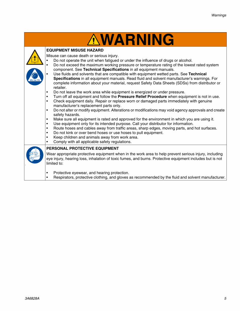
EQUIPMENT MISUSE HAZARDMisuse can cause death or serious injury.• Do not operate the unit when fatigued or under the influence of drugs or alcohol.• Do not exceed the maximum working pressure or temperature rating of the lowest rated system
component. See Technical Specifications in all equipment manuals.• Use fluids and solvents that are compatible with equipment wetted parts. See Technical
Specifications in all equipment manuals. Read fluid and solvent manufacturer’s warnings. For complete information about your material, request Safety Data Sheets (SDSs) from distributor or retailer.
• Do not leave the work area while equipment is energized or under pressure.• Turn off all equipment and follow the Pressure Relief Procedure when equipment is not in use.• Check equipment daily. Repair or replace worn or damaged parts immediately with genuine
manufacturer’s replacement parts only.• Do not alter or modify equipment. Alterations or modifications may void agency approvals and create
safety hazards.• Make sure all equipment is rated and approved for the environment in which you are using it.• Use equipment only for its intended purpose. Call your distributor for information.• Route hoses and cables away from traffic areas, sharp edges, moving parts, and hot surfaces.• Do not kink or over bend hoses or use hoses to pull equipment.• Keep children and animals away from work area.• Comply with all applicable safety regulations.
PERSONAL PROTECTIVE EQUIPMENTWear appropriate protective equipment when in the work area to help prevent serious injury, including eye injury, hearing loss, inhalation of toxic fumes, and burns. Protective equipment includes but is not limited to:
• Protective eyewear, and hearing protection. • Respirators, protective clothing, and gloves as recommended by the fluid and solvent manufacturer.
Installation
6 3A6828A
Installation
Grounding
Enclosure, controller, and transducer: grounded through the power cord. Do not modify the plug pro-vided; if it does not fit the outlet, have the proper outlet installed by a qualified electrician.
Pump: refer to your pump’s instruction manual.
Air and fluid hoses: use only electrically conductive hoses.
Air compressor: follow manufacturer’s recommenda-tions.
Fluid supply container: follow local code.
Mounting the EnclosureSee Typical Installation, on page 8, for location of the enclosure relative to the pneumatic intensifier pump. See Dimensions, on page 30, to determine the size of the flat surface needed for the enclosure.
1. Open the enclosure and locate the mounting holes near each corner of the backplate. See FIG. 4 on page 9.
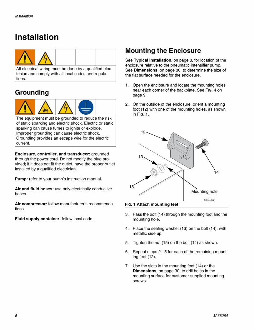
2. On the outside of the enclosure, orient a mounting foot (12) with one of the mounting holes, as shown in FIG. 1.
3. Pass the bolt (14) through the mounting foot and the mounting hole.
4. Place the sealing washer (13) on the bolt (14), with metallic side up.
5. Tighten the nut (15) on the bolt (14) as shown.
6. Repeat steps 2 - 5 for each of the remaining mount-ing feet (12).
7. Use the slots in the mounting feet (14) or the Dimensions, on page 30, to drill holes in the mounting surface for customer-supplied mounting screws.
All electrical wiring must be done by a qualified elec-trician and comply with all local codes and regula-tions.
The equipment must be grounded to reduce the risk of static sparking and electric shock. Electric or static sparking can cause fumes to ignite or explode. Improper grounding can cause electric shock. Grounding provides an escape wire for the electric current.
FIG. 1 Attach mounting feet
12
13
15
14
Mounting hole
Installation
3A6828A 7
Connecting the Transducer
1. Follow the Pressure Relief Procedure on page 11.
2. Turn the disconnect switch (8) to the OFF position. (See FIG. 4 on page 9.)
3. Attach the transducer (R) close to the pump’s outlet port (L). (See FIG. 3 on page 8.)
4. Connect the transducer cable (P) from the trans-ducer connection (10) to the transducer (R).
5. Turn the disconnect switch (8) to the ON position.
Updating the Software
The PT2020 has two USB ports for updating the soft-ware, and for importing and exporting data.
NOTE: Settings and pressure test data may be lost when updating software. See File Management, on page 23, for saving and restoring settings and pressure test data.
1. Follow the Pressure Relief Procedure on page 11.
2. Turn the disconnect switch to the OFF position. (See FIG. 4 on page 9.)
3. Disconnect the PT2020 from the AC outlet.
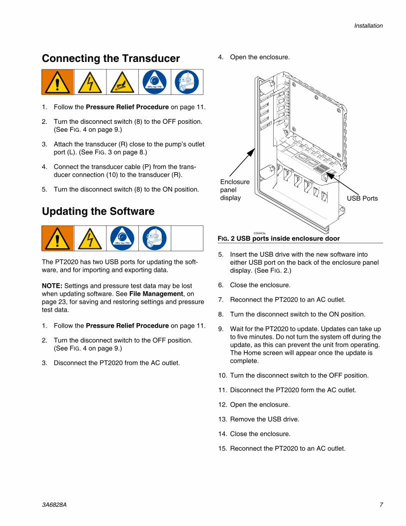
4. Open the enclosure.
5. Insert the USB drive with the new software into either USB port on the back of the enclosure panel display. (See FIG. 2.)
6. Close the enclosure.
7. Reconnect the PT2020 to an AC outlet.
8. Turn the disconnect switch to the ON position.
9. Wait for the PT2020 to update. Updates can take up to five minutes. Do not turn the system off during the update, as this can prevent the unit from operating. The Home screen will appear once the update is complete.
10. Turn the disconnect switch to the OFF position.
11. Disconnect the PT2020 form the AC outlet.
12. Open the enclosure.
13. Remove the USB drive.
14. Close the enclosure.
15. Reconnect the PT2020 to an AC outlet.
FIG. 2 USB ports inside enclosure door
USB Ports
Enclosurepanel display
Installation
8 3A6828A
Typical Installation
FIG. 3 is an example of enclosure installation with a pressure test system. Your installation may differ from what is shown here.
Components Supplied by HiPThe following components, see FIG. 3, are supplied by HiP:
Additional Modular System ComponentsThe following components, see FIG. 3, are available from HiP or supplied by the customer:
FIG. 3: System Layout
A
B*C*
D*
E*
Fluid SupplyContainer
F
G
H*
J
N* K
L
M
P*
R*
S
Enclosurepanel display
B Pneumatic Filter*
D PT2020 Controller*
P Transducer Cable*
R Transducer*
S Power Cord*
* Required component
A Main Pneumatic Supply Line
C Bleed-type Master Pneumatic Valve*
E Pump*
F Strainer (at the fluid supply container)
G Fluid Shutoff Valve (outlet only)
H Fluid Pressure Relief Valve*
J Fluid Inlet Line
K Inlet Port
L Outlet Port
M Fluid Outlet Line to Hydraulic System
N Supply Fluid Shutoff Valve*
* Required component
Installation
3A6828A 9
Enclosure Components
FIG. 4: Enclosure Components
6
9
8
7
32
1
45
1011
12
Mounting holes
Mounting holes
1 Electronic regulator
2 M12 cable connection
3 Pneumatic hose connection
4 Regulator base
5 Base screws
6 Backplate
7 Filter
8 Disconnect switch
9 Power cable connection
10 Pressure transducer connection
11 I/O cards
12 Ethernet connections
Installation
10 3A6828A
Wiring Diagram
FIG. 5: Wiring Diagram
0
ABCDEFGHIJKL
12
34
56
78
910
1112
1314
15
Operation
3A6828A 11
Operation
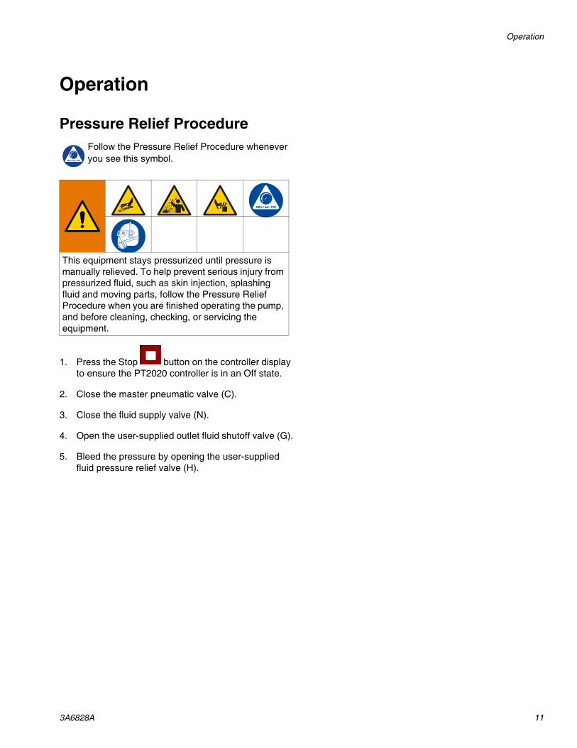
Pressure Relief ProcedureFollow the Pressure Relief Procedure whenever you see this symbol.
1. Press the Stop button on the controller display to ensure the PT2020 controller is in an Off state.
2. Close the master pneumatic valve (C).
3. Close the fluid supply valve (N).
4. Open the user-supplied outlet fluid shutoff valve (G).
5. Bleed the pressure by opening the user-supplied fluid pressure relief valve (H).
This equipment stays pressurized until pressure is manually relieved. To help prevent serious injury from pressurized fluid, such as skin injection, splashing fluid and moving parts, follow the Pressure Relief Procedure when you are finished operating the pump, and before cleaning, checking, or servicing the equipment.
Controller Operation
12 3A6828A
Controller Operation
Navigation
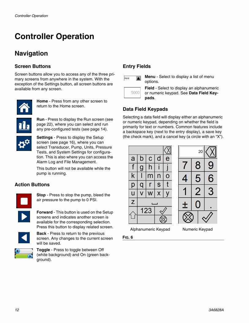
Screen ButtonsScreen buttons allow you to access any of the three pri-mary screens from anywhere in the system. With the exception of the Settings button, all screen buttons are available from any screen.
Action Buttons
Entry Fields
Data Field KeypadsSelecting a data field will display either an alphanumeric or numeric keypad, depending on whether the field is primarily for text or numbers. Common features include a backspace key (next to the entry display), a save key (the check mark), and a cancel key (a circle with an “X”).
Home - Press from any other screen to return to the Home screen.
Run - Press to display the Run screen (see page 22), where you can select and run any pre-configured tests (see page 14).
Settings - Press to display the Setup screen (see page 16), where you can select Transducer, Pump, Units, Pressure Tests, and System Settings for configura-tion. This is also where you can access the Alarm Log and File Management.
This button will not be available while the pump is running.
Stop - Press to stop the pump, bleed the air pressure to the pump to 0 PSI.
Forward - This button is used on the Setup screens and indicates another screen is available for the corresponding selection. Press this button to display related screen.
Back - Press to return to the previous screen. Any changes to the current screen will be saved.
Toggle - Press to toggle between Off (white background) and On (green back-ground).
Menu - Select to display a list of menu options.
Field - Select to display an alphanumeric or numeric keypad. See Data Field Key-pads.
FIG. 6
Alphanumeric Keypad Numeric Keypad
Controller Operation
3A6828A 13
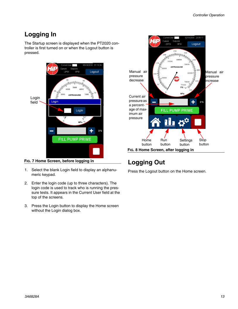
Logging InThe Startup screen is displayed when the PT2020 con-troller is first turned on or when the Logout button is pressed.
1. Select the blank Login field to display an alphanu-meric keypad.
2. Enter the login code (up to three characters). The login code is used to track who is running the pres-sure tests. It appears in the Current User field at the top of the screens.
3. Press the Login button to display the Home screen without the Login dialog box.
Logging OutPress the Logout button on the Home screen.
FIG. 7 Home Screen, before logging in
Login field
FIG. 8 Home Screen, after logging in
Manual airpressuredecrease
Manual airpressureincrease
Homebutton
Runbutton
Settingsbutton
Stopbutton
Current air pressure as a percent-age of max-imum air pressure
Controller Operation
14 3A6828A
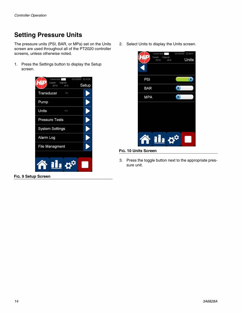
Setting Pressure UnitsThe pressure units (PSI, BAR, or MPa) set on the Units screen are used throughout all of the PT2020 controller screens, unless otherwise noted.
1. Press the Settings button to display the Setup screen.
2. Select Units to display the Units screen.
3. Press the toggle button next to the appropriate pres-sure unit.
FIG. 9 Setup Screen
FIG. 10 Units Screen
Controller Operation
3A6828A 15
Setting Up the Transducer
Selecting a TransducerThe following steps assume you have already installed a Graco-supplied pressure transducer.
1. Press the Settings button to display the Setup screen.
2. Select Transducer to display the Transducer screen.
3. Press the toggle button next to the maximum pres-sure (in PSI) rated for your transducer.
NOTE: For non-Graco-supplied transducers, or other custom 4-20 mA transducers, select Custom to display the Custom screen, and enter the Max Transducer Pressure rated for the transducer.
FIG. 11 Transducer Screen
FIG. 12 Transducer Custom Screen
Controller Operation
16 3A6828A
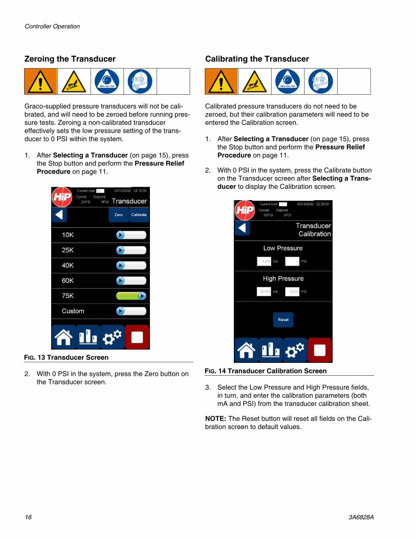
Zeroing the Transducer
Graco-supplied pressure transducers will not be cali-brated, and will need to be zeroed before running pres-sure tests. Zeroing a non-calibrated transducer effectively sets the low pressure setting of the trans-ducer to 0 PSI within the system.
1. After Selecting a Transducer (on page 15), press the Stop button and perform the Pressure Relief Procedure on page 11.
2. With 0 PSI in the system, press the Zero button on the Transducer screen.
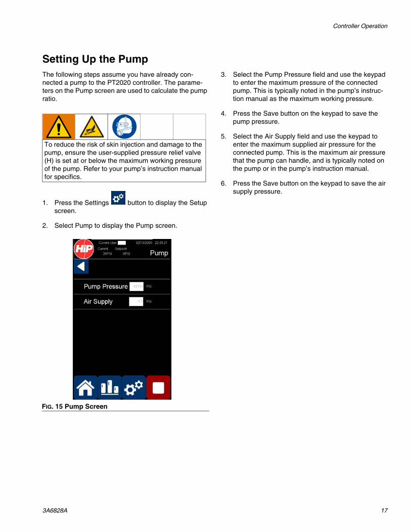
Calibrating the Transducer
Calibrated pressure transducers do not need to be zeroed, but their calibration parameters will need to be entered the Calibration screen.
1. After Selecting a Transducer (on page 15), press the Stop button and perform the Pressure Relief Procedure on page 11.
2. With 0 PSI in the system, press the Calibrate button on the Transducer screen after Selecting a Trans-ducer to display the Calibration screen.
3. Select the Low Pressure and High Pressure fields, in turn, and enter the calibration parameters (both mA and PSI) from the transducer calibration sheet.
NOTE: The Reset button will reset all fields on the Cali-bration screen to default values.
FIG. 13 Transducer Screen
FIG. 14 Transducer Calibration Screen
Controller Operation
3A6828A 17
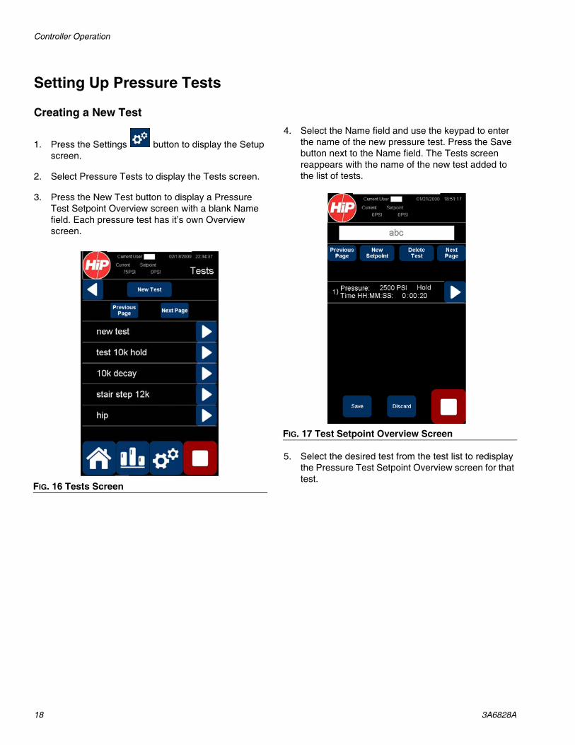
Setting Up the PumpThe following steps assume you have already con-nected a pump to the PT2020 controller. The parame-ters on the Pump screen are used to calculate the pump ratio.
1. Press the Settings button to display the Setup screen.
2. Select Pump to display the Pump screen.
3. Select the Pump Pressure field and use the keypad to enter the maximum pressure of the connected pump. This is typically noted in the pump’s instruc-tion manual as the maximum working pressure.
4. Press the Save button on the keypad to save the pump pressure.
5. Select the Air Supply field and use the keypad to enter the maximum supplied air pressure for the connected pump. This is the maximum air pressure that the pump can handle, and is typically noted on the pump or in the pump’s instruction manual.
6. Press the Save button on the keypad to save the air supply pressure.
To reduce the risk of skin injection and damage to the pump, ensure the user-supplied pressure relief valve (H) is set at or below the maximum working pressure of the pump. Refer to your pump’s instruction manual for specifics.
FIG. 15 Pump Screen
Controller Operation
18 3A6828A
Setting Up Pressure Tests
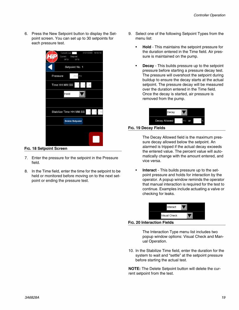
Creating a New Test
1. Press the Settings button to display the Setup screen.
2. Select Pressure Tests to display the Tests screen.
3. Press the New Test button to display a Pressure Test Setpoint Overview screen with a blank Name field. Each pressure test has it’s own Overview screen.
4. Select the Name field and use the keypad to enter the name of the new pressure test. Press the Save button next to the Name field. The Tests screen reappears with the name of the new test added to the list of tests.
5. Select the desired test from the test list to redisplay the Pressure Test Setpoint Overview screen for that test.
FIG. 16 Tests Screen
FIG. 17 Test Setpoint Overview Screen
Controller Operation
3A6828A 19
6. Press the New Setpoint button to display the Set-point screen. You can set up to 30 setpoints for each pressure test.
7. Enter the pressure for the setpoint in the Pressure field.
8. In the Time field, enter the time for the setpoint to be held or monitored before moving on to the next set-point or ending the pressure test.
9. Select one of the following Setpoint Types from the menu list:
• Hold - This maintains the setpoint pressure for the duration entered in the Time field. Air pres-sure is maintained on the pump.
• Decay - This builds pressure up to the setpoint pressure before starting a pressure decay test. The pressure will overshoot the setpoint during buildup to ensure the decay starts at the actual setpoint. The pressure decay will be measured over the duration entered in the Time field. Once the decay is started, air pressure is removed from the pump.
The Decay Allowed field is the maximum pres-sure decay allowed below the setpoint. An alarmed is tripped if the actual decay exceeds the entered value. The percent value will auto-matically change with the amount entered, and vice versa.
• Interact - This builds pressure up to the set-point pressure and holds for interaction by the operator. A popup window reminds the operator that manual interaction is required for the test to continue. Examples include actuating a valve or checking for leaks.
The Interaction Type menu list includes two popup window options: Visual Check and Man-ual Operation.
10. In the Stabilize Time field, enter the duration for the system to wait and “settle” at the setpoint pressure before starting the actual test.
NOTE: The Delete Setpoint button will delete the cur-rent setpoint from the test.
FIG. 18 Setpoint Screen
FIG. 19 Decay Fields
FIG. 20 Interaction Fields
Controller Operation
20 3A6828A
Setting Up the System
1. Press the Settings button to display the Setup screen.
2. Select System Settings to display the System screen.
Setting Date and Time1. Select Date/Time on the System screen to display
the System Date/Time screen.
2. Enter the current date in the Date fields.
3. Enter the current time (in 24-hr format) in the Time fields.
4. Press the Back button to return to the System screen.
FIG. 21 System Screen
FIG. 22 System Date/Time Screen
Controller Operation
3A6828A 21
Verifying the System InformationSelect System Info on the System screen to display the System Info screen. This screen displays the IP address for the controller, the version of the installed controller software, and the current language setting.
NOTE: English is currently the only language available. Additional languages can be selected from this screen as they become available.
Setting the Overpressure Limit
This sets a maximum pressure allowed over the highest setpoint for a pressure test. Any pressure over the max-imum pressure (the highest setpoint pressure plus the overpressure limit) will trigger an alarm and stop the test.
Example: A pressure test may include setpoints of 5000, 7000, and 10,000 PSI. If the overpressure limit is set to 500 PSI, the maximum pressure allowed during the pressure test is 10,500 PSI.
1. Enter the overpressure limit in the Over Press Limit field.
Setting the GainThe gain determines how quickly the system builds pressure, with 1 being the slowest and 10 being the fast-est.
NOTE: A higher gain can cause larger overshoots when building target setpoints, which may affect the test accu-racy or over-pressurize components. A lower gain can increase the time it takes to build pressure when testing large volumes. Increase or decrease the gain accord-ingly for your application.
1. Enter the gain (between 1 and 10) in the Gain field.
FIG. 23 System Info Screen
To reduce the risk of skin injection and damage to the pump, set the overpressure limit to keep the maxi-mum pressure attainable under the maximum working pressure of the pump. Refer to your pump’s instruc-tion manual for specifics.
Run Screen Operations
22 3A6828A
Run Screen Operations
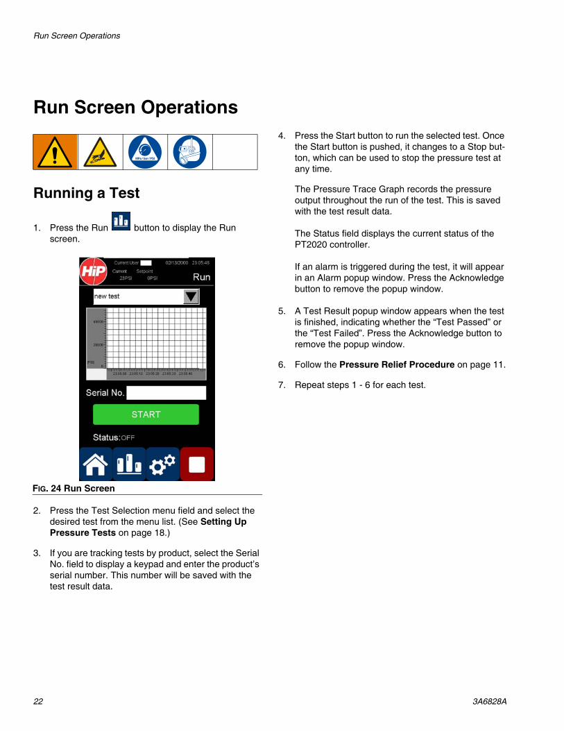
Running a Test
1. Press the Run button to display the Run screen.
2. Press the Test Selection menu field and select the desired test from the menu list. (See Setting Up Pressure Tests on page 18.)
3. If you are tracking tests by product, select the Serial No. field to display a keypad and enter the product’s serial number. This number will be saved with the test result data.
4. Press the Start button to run the selected test. Once the Start button is pushed, it changes to a Stop but-ton, which can be used to stop the pressure test at any time.
The Pressure Trace Graph records the pressure output throughout the run of the test. This is saved with the test result data.
The Status field displays the current status of the PT2020 controller.
If an alarm is triggered during the test, it will appear in an Alarm popup window. Press the Acknowledge button to remove the popup window.
5. A Test Result popup window appears when the test is finished, indicating whether the “Test Passed” or the “Test Failed”. Press the Acknowledge button to remove the popup window.
6. Follow the Pressure Relief Procedure on page 11.
7. Repeat steps 1 - 6 for each test.
FIG. 24 Run Screen
File Management
3A6828A 23
File Management
Accessing the USB Ports
1. Follow the Pressure Relief Procedure on page 11.
2. Turn the disconnect switch to the OFF position.
3. Disconnect the PT2020 from the AC outlet.
4. Open the enclosure.
5. Insert a USB drive into either USB port.
6. Close the enclosure.
7. Reconnect the PT2020 to an AC outlet.
8. Turn the disconnect switch to the ON position.
Managing Pressure Test Results
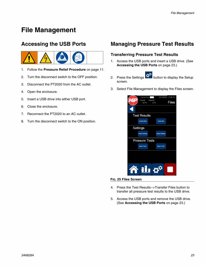
Transferring Pressure Test Results1. Access the USB ports and insert a USB drive. (See
Accessing the USB Ports on page 23.)
2. Press the Settings button to display the Setup screen.
3. Select File Management to display the Files screen.
4. Press the Test Results-->Transfer Files button to transfer all pressure test results to the USB drive.
5. Access the USB ports and remove the USB drive. (See Accessing the USB Ports on page 23.)
FIG. 25 Files Screen
File Management
24 3A6828A
Purging Pressure Test Results
1. Press the Settings button to display the Setup screen.
2. Select File Management to display the Files screen.
3. Press the Test Results-->Purge Files button to delete all pressure test results from the PT2020 controller.
Transferring System Settings
Exporting System SettingsThis is useful for saving current settings when updating the PT2020 software.
1. Access the USB ports and insert a USB drive. (See Accessing the USB Ports on page 23.)
2. Press the Settings button to display the Setup screen.
3. Select File Management to display the Files screen.
4. Press the Settings-->Export Settings button to transfer all system settings to the USB drive.
5. Access the USB ports and remove the USB drive. (See Accessing the USB Ports on page 23.)
Importing System SettingsThis is useful for restoring saved settings after updating the PT2020 software.
1. Access the USB ports and insert a USB drive. (See Accessing the USB Ports on page 23.)
2. Press the Settings button to display the Setup screen.
3. Select File Management to display the Files screen.
4. Press the Settings-->Import Settings button to trans-fer system settings from the USB drive.
5. Access the USB ports and remove the USB drive. (See Accessing the USB Ports on page 23.)
Transferring Pressure Tests
Exporting Pressure Tests Settings1. Access the USB ports and insert a USB drive. (See
Accessing the USB Ports on page 23.)
2. Press the Settings button to display the Setup screen.
3. Select File Management to display the Files screen.
4. Press the Pressure Tests-->Export Tests button to transfer pressure test settings to the USB drive.
5. Access the USB ports and remove the USB drive. (See Accessing the USB Ports on page 23.)
Importing Pressure Tests Settings1. Access the USB ports and insert a USB drive. (See
Accessing the USB Ports on page 23.)
2. Press the Settings button to display the Setup screen.
3. Select File Management to display the Files screen.
4. Press the Pressure Tests-->Import Tests button to transfer pressure test settings from the USB drive.
5. Access the USB ports and remove the USB drive. (See Accessing the USB Ports on page 23.)
Troubleshooting
3A6828A 25
Troubleshooting
1. Follow Pressure Relief Procedure, page 11, before checking or repairing pump.
2. Turn the disconnect switch (8) to the OFF position.
3. Disconnect the PT2020 from the AC outlet.
4. Check all possible problems and causes before dis-assembling pump.
5. Reconnect the PT2020 to the AC outlet after trou-bleshooting.
6. Turn the disconnect switch (8) to the ON position.
Alarm Trigger Condition Return to Standby Condition Solution
I/O Fault Whenever the PLC cannot communicate with the I/O cards. The I/O cards control the communication to the sen-sors and items being con-trolled.
Once all I/O is detected and user acknowledges the alarm.
Check the Ethernet cable that connects the PLC to the I/O cards and reseat the connec-tions, if necessary.
Contact Graco Tech Assis-tance.
No Transducer Whenever the 4-20 mA signal is not in range.
Once the alarm is acknowl-edged and the transducer is detected.
Verify the transducer is prop-erly connected by reseating the cable connections.
Contact Graco Tech Assis-tance.
Pressure Test Failed
Interaction failed by user, or pressure decay failed.
Once alarm is acknowledged and pressure is relieved.
Determine what caused the test to fail and rerun the test.
Over Pressure Pressure went above the max-imum test pressure + the over pressure allowed threshold.
Once the alarm is acknowl-edged and pressure is relieved.
Check for leaks in the system.
Lower the gain setting.
Increase the over pressure threshold if safe to do so.
Test Unsafe A test to be run would result in the pressure transducer being over pressured.
Once the alarm is acknowl-edged.
Pick a different pressure test to run.
Verify the transducer matches the transducer selected on the Transducer screen.
Use a transducer that is prop-erly sized for the pressure test.
Troubleshooting
26 3A6828A
Viewing Alarm Events
1. Press the Settings button to display the Setup screen.
2. Select Alarm Log to display the Alarm Log screen. Alarm events are listed in the order they occurred.
Test Unachievable A test to be run is over the maximum pressure of the pump.
Once the alarm is acknowl-edged.
Pick a different pressure test to run.
Verify the pump running the test matches settings on the Pump screen.
Use the proper pump for the test.
Leak Detected When the pressure drops below 90% of the setpoint for 5 seconds when doing a pres-sure hold test.
Once the alarm is acknowl-edged and pressure is relieved.
Check for leaks in the system.
Alarm Trigger Condition Return to Standby Condition Solution
FIG. 26 Alarm Log Screen
Repair
3A6828A 27
Repair
Replacing the TransducerSee Kits and Accessories, on page 25, for transducer kit numbers.
1. Follow the Pressure Relief Procedure on page 11.
2. Turn the disconnect switch (8) to the OFF position.
3. Disconnect the transducer cable (P) from the trans-ducer (R). (See FIG. 3 on page 8.)
4. Replace the transducer (R) near the pump’s outlet port (L).
5. Connect the transducer cable (P) to the new trans-ducer (R).
6. Turn the disconnect switch (8) to the ON position.
Replacing the Electronic Air RegulatorSee Kits and Accessories, on page 25, for air regula-tor kit numbers.
1. Follow the Pressure Relief Procedure on page 11.
2. Turn the disconnect switch (8) to the OFF position.
3. Disconnect the PT2020 from the AC outlet.
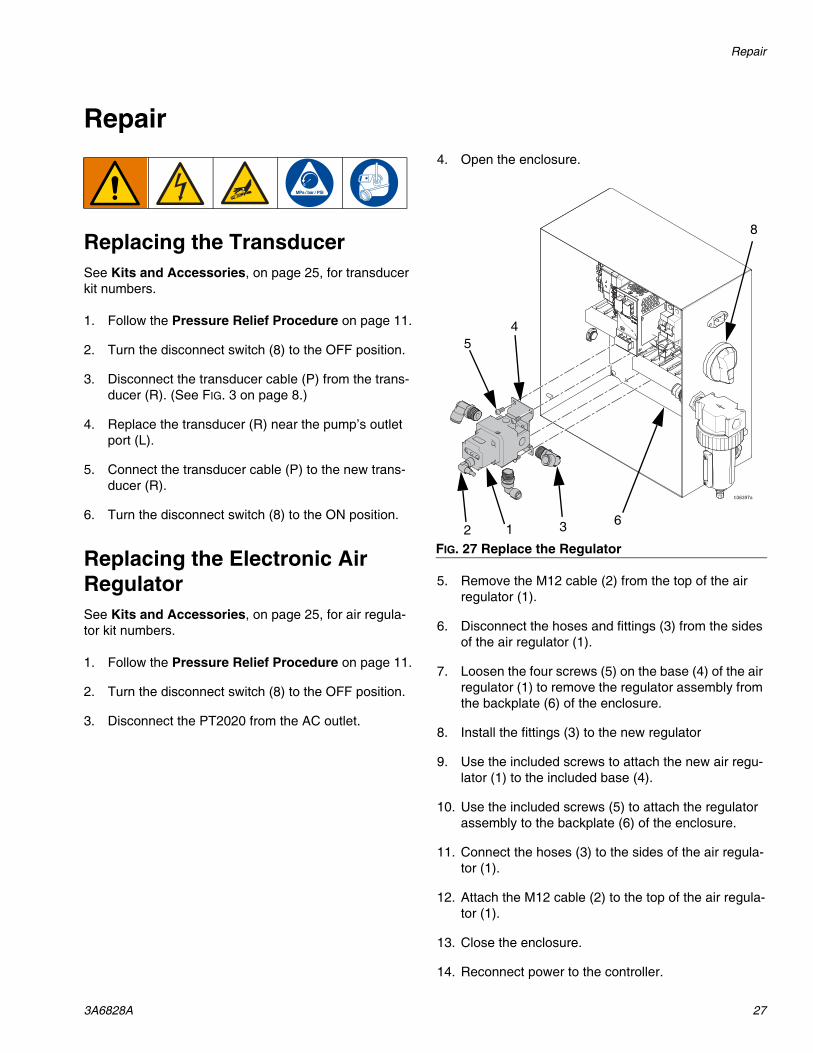
4. Open the enclosure.
5. Remove the M12 cable (2) from the top of the air regulator (1).
6. Disconnect the hoses and fittings (3) from the sides of the air regulator (1).
7. Loosen the four screws (5) on the base (4) of the air regulator (1) to remove the regulator assembly from the backplate (6) of the enclosure.
8. Install the fittings (3) to the new regulator
9. Use the included screws to attach the new air regu-lator (1) to the included base (4).
10. Use the included screws (5) to attach the regulator assembly to the backplate (6) of the enclosure.
11. Connect the hoses (3) to the sides of the air regula-tor (1).
12. Attach the M12 cable (2) to the top of the air regula-tor (1).
13. Close the enclosure.
14. Reconnect power to the controller.
FIG. 27 Replace the Regulator
3
54
2 16
8
Parts
28 3A6828A
Parts
PT2020 Enclosure
2
2 1 3
5
4
1214
13
15
8
8
16
9
10
1718
11
7
26
19
20
21
22
23
2425
Kits and Accessories
3A6828A 29
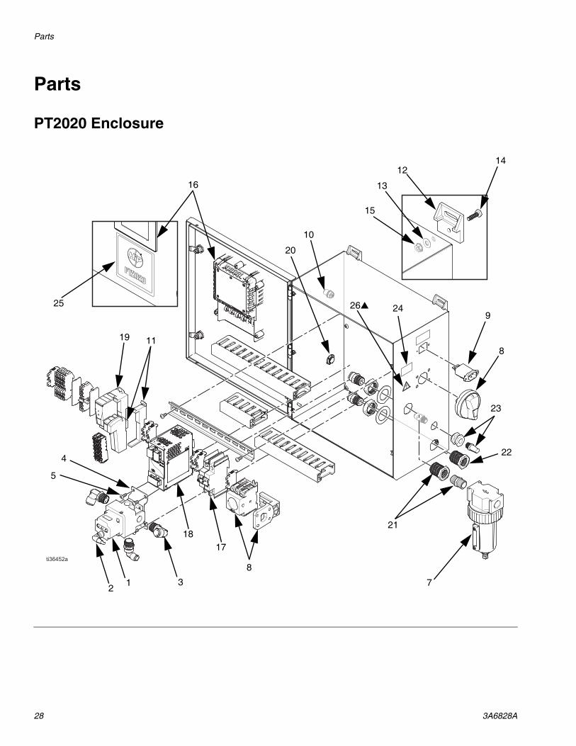
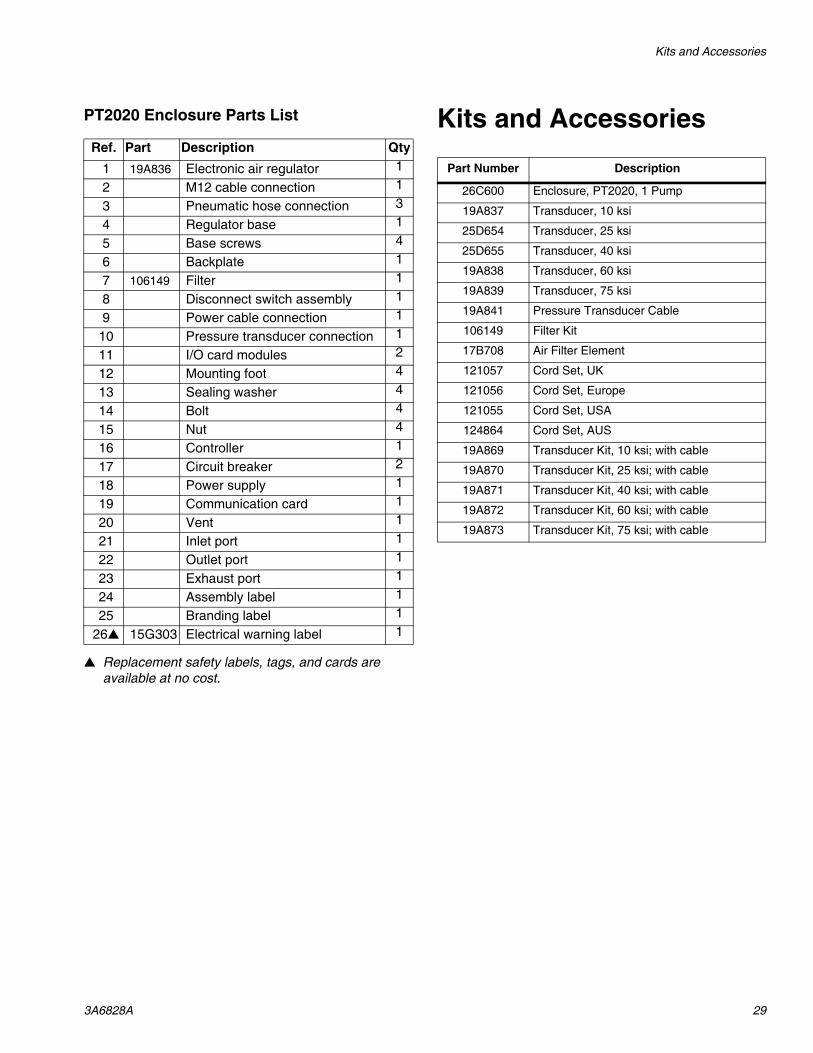
PT2020 Enclosure Parts List
Replacement safety labels, tags, and cards are available at no cost.
Kits and AccessoriesRef. Part Description Qty
1 19A836 Electronic air regulator 1
2 M12 cable connection 1
3 Pneumatic hose connection 3
4 Regulator base 1
5 Base screws 4
6 Backplate 1
7 106149 Filter 1
8 Disconnect switch assembly 1
9 Power cable connection 1
10 Pressure transducer connection 1
11 I/O card modules 2
12 Mounting foot 4
13 Sealing washer 4
14 Bolt 4
15 Nut 4
16 Controller 1
17 Circuit breaker 2
18 Power supply 1
19 Communication card 1
20 Vent 1
21 Inlet port 1
22 Outlet port 1
23 Exhaust port 1
24 Assembly label 1
25 Branding label 1
26 15G303 Electrical warning label 1
Part Number Description
26C600 Enclosure, PT2020, 1 Pump
19A837 Transducer, 10 ksi
25D654 Transducer, 25 ksi
25D655 Transducer, 40 ksi
19A838 Transducer, 60 ksi
19A839 Transducer, 75 ksi
19A841 Pressure Transducer Cable
106149 Filter Kit
17B708 Air Filter Element
121057 Cord Set, UK
121056 Cord Set, Europe
121055 Cord Set, USA
124864 Cord Set, AUS
19A869 Transducer Kit, 10 ksi; with cable
19A870 Transducer Kit, 25 ksi; with cable
19A871 Transducer Kit, 40 ksi; with cable
19A872 Transducer Kit, 60 ksi; with cable
19A873 Transducer Kit, 75 ksi; with cable
Dimensions
30 3A6828A
Dimensions
PT2020 Controller
FIG. 28 PT2020 Controller Dimensions and Mounting Slots
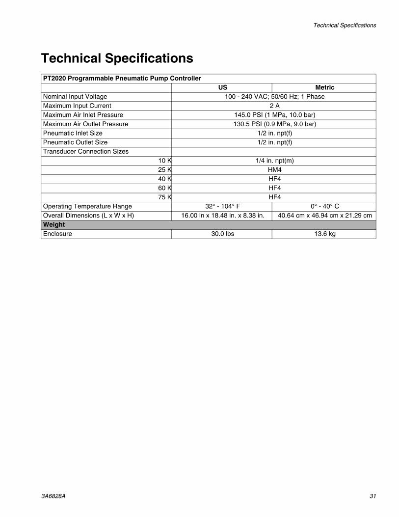
US MetricNominal Input Voltage 100 - 240 VAC; 50/60 Hz; 1 PhaseMaximum Input Current 2 AMaximum Air Inlet Pressure 145.0 PSI (1 MPa, 10.0 bar)Maximum Air Outlet Pressure 130.5 PSI (0.9 MPa, 9.0 bar)Pneumatic Inlet Size 1/2 in. npt(f)Pneumatic Outlet Size 1/2 in. npt(f)Transducer Connection Sizes
10 K 1/4 in. npt(m)25 K HM440 K HF460 K HF475 K HF4
Operating Temperature Range 32° - 104° F 0° - 40° COverall Dimensions (L x W x H) 16.00 in x 18.48 in. x 8.38 in. 40.64 cm x 46.94 cm x 21.29 cmWeightEnclosure 30.0 lbs 13.6 kg
All written and visual data contained in this document reflects the latest product information available at the time of publication. Graco reserves the right to make changes at any time without notice.
Original instructions. This manual contains English. MM 3A6828Graco Headquarters: Minneapolis
International Offices: Belgium, China, Japan, Korea
GRACO HIGH PRESSURE EQUIPMENT CO. • 2955 West 17th Street • ERIE PA 16305 • USACopyright 2019, Graco Inc. All Graco manufacturing locations are registered to ISO 9001.
www.highpressure.comRevision A, 5/2019
Graco High Pressure Equipment Company Standard WarrantyGraco High Pressure Equipment Company warrants all equipment referenced in this document which is manufactured by Graco High Pressure Equipment Company and bearing its name to be free from defects in material and workmanship on the date of sale to the original purchaser for use. With the exception of any special, extended, or limited warranty published by Graco High Pressure Equipment Company, Graco High Pressure Equipment Company will, for a period of twelve months from the date of sale, repair or replace any part of the equipment determined by Graco High Pressure Equipment Company to be defective. This warranty applies only when the equipment is installed, operated and maintained in accordance with Graco High Pressure Equipment Company’s written recommendations.
This warranty does not cover, and Graco High Pressure Equipment Company shall not be liable for general wear and tear, or any malfunction, damage or wear caused by faulty installation, misapplication, abrasion, corrosion, inadequate or improper maintenance, negligence, accident, tampering, or substitution of non-Graco High Pressure Equipment Company component parts. Nor shall Graco High Pressure Equipment Company be liable for malfunction, damage or wear caused by the incompatibility of Graco High Pressure Equipment Company equipment with structures, accessories, equipment or materials not supplied by Graco High Pressure Equipment Company, or the improper design, manufacture, installation, operation or maintenance of structures, accessories, equipment or materials not supplied by Graco High Pressure Equipment Company.
This warranty is conditioned upon the prepaid return of the equipment claimed to be defective to an authorized Graco High Pressure Equipment Company distributor for verification of the claimed defect. If the claimed defect is verified, Graco High Pressure Equipment Company will repair or replace free of charge any defective parts. The equipment will be returned to the original purchaser transportation prepaid. If inspection of the equipment does not disclose any defect in material or workmanship, repairs will be made at a reasonable charge, which charges may include the costs of parts, labor, and transportation.
THIS WARRANTY IS EXCLUSIVE, AND IS IN LIEU OF ANY OTHER WARRANTIES, EXPRESS OR IMPLIED, INCLUDING BUT NOT LIMITED TO WARRANTY OF MERCHANTABILITY OR WARRANTY OF FITNESS FOR A PARTICULAR PURPOSE.
Graco High Pressure Equipment Company’s sole obligation and buyer’s sole remedy for any breach of warranty shall be as set forth above. The buyer agrees that no other remedy (including, but not limited to, incidental or consequential damages for lost profits, lost sales, injury to person or property, or any other incidental or consequential loss) shall be available. Any action for breach of warranty must be brought within two (2) years of the date of sale.
GRACO HIGH PRESSURE EQUIPMENT COMPANY MAKES NO WARRANTY, AND DISCLAIMS ALL IMPLIED WARRANTIES OF MERCHANTABILITY AND FITNESS FOR A PARTICULAR PURPOSE, IN CONNECTION WITH ACCESSORIES, EQUIPMENT, MATERIALS OR COMPONENTS SOLD BUT NOT MANUFACTURED BY GRACO HIGH PRESSURE EQUIPMENT COMPANY. These items sold, but not manufactured by Graco High Pressure Equipment Company (such as electric motors, switches, hose, etc.), are subject to the warranty, if any, of their manufacturer. Graco High Pressure Equipment Company will provide purchaser with reasonable assistance in making any claim for breach of these warranties.
In no event will Graco High Pressure Equipment Company be liable for indirect, incidental, special or consequential damages resulting from Graco High Pressure Equipment Company supplying equipment hereunder, or the furnishing, performance, or use of any products or other goods sold hereto, whether due to a breach of contract, breach of warranty, the negligence of Graco High Pressure Equipment Company, or otherwise.
FOR GRACO HIGH PRESSURE EQUIPMENT COMPANY CANADA CUSTOMERSThe Parties acknowledge that they have required that the present document, as well as all documents, notices and legal proceedings entered into, given or instituted pursuant hereto or relating directly or indirectly hereto, be drawn up in English. Les parties reconnaissent avoir convenu que la rédaction du présente document sera en Anglais, ainsi que tous documents, avis et procédures judiciaires exécutés, donnés ou intentés, à la suite de ou en rapport, directement ou indirectement, avec les procédures concernées.
Graco High Pressure Equipment Company InformationFor the latest information about Graco High Pressure Equipment Company products, visit www.highpressure.com.
TO PLACE AN ORDER, contact your Graco High Pressure Equipment Company distributor or call to identify the nearest distributor.Toll Free: 1-800-289-7447 Fax: 814-838-6075