PTFE Hose One Firestone Drive ❒ Suffield, CT 06078 ❒ Telephone (860) 668-1285 ❒ Fax (860) 668-2353 ENGINEERING AND DESIGN - Our technical staff is next to none. Ready to respond to your special needs, Teleflex engineers have countless ideas and solutions to any fluid handling problem. MARKETING - Teleflex has been a marketing leader since its inception over 50 years ago. From concept to sale, Teleflex provides the products and services that excel wherever they are specified. We are certain we can help you. DISTRIBUTION - The key to Teleflex Fluid Systems service excellence is in our distributor organization. Carefully selected and trained, Teleflex distributors are service oriented experts in the application of PTFE hose. Local distributor inventories generate minimum wait with maximum service satisfaction. As a team, Teleflex delivers. The information set forth in this catalog was developed using accurate testing and engineering techniques. Use of this information is the customers’ responsibility. The sole respon- sibility or liability of Teleflex Fluid Systems is limited to replacement of Teleflex hose products found defective in materials or workmanship. Dimensions and materials cited in this catalog are subject to change or correction without notice. If certification of dimen- sions or materials is required, please contact Teleflex. Tensile Strength, 73°F 1500-3000 lb./sq. in. Elongation, 73° F 100-200% Stiffness, 73° 60,000 lb./sq. in. Impact Strength, Izod - 70°F 2.0 ft. - lb./in. 73°F 3.5 ft. - lb./in. 170°F 6.0 ft. - lb./in. Hardness Durometer D55-D70 Compressive Stress at 1% Deformation, 73°F 600 lb./sq. in. at 1% Offset, 73°F 1000 lb./sq. in. Deformation Under Load, 122°F 1200 lb./sq. in., 24 hrs. 4-8% 2000 lb./sq. in., 24 hrs. 25% Heat-Distortion Temperature, 66 lb./sq. in. 250°F Coefficient of Linear Thermal Expansion Per °F, 77-140°F 5.5x10- 5 Thermal Conductivity, 0.18 in. 1.7 B.T.U./hr./sq.ft./°F/in. Specific Heat 0.25 B.T.U./lb./°F Water Absorption 0.0° Flammability Nonflammable Specific Gravity 2.1-2.3 PROPERTIES OF PTFE 1 p.s.i. = 0.0689 bar 1 Atms = 14.70 p.s.i. 1 bar = 14.5035 p.s.i. 1 Atms = 29.92 in. mercury 1 p.s.i. = 0.0703 Kg/sq.cm 1 m. = 3.281 ft. 1 Kg/sq.cm = 14.22 p.s.i. 1 ft. = 0.3048 m. USEFUL CONVERSIONS
ENGINEERING AND DESIGN - Our technical staff is next to none. Ready to respond to your special needs, Teleflex engineers have countless ideas and solutions to any fluid handling problem. MARKETING - Teleflex has been a marketing leader since its inception over 50 years ago. From concept to sale, Teleflex provides the products and services that excel wherever they are specified. We are certain we can help you. DISTRIBUTION - The key to Teleflex Fluid Systems service excellence is in our distributor organization. Carefully selected and trained, Teleflex distributors are service oriented experts in the application of PTFE hose. Local distributor inventories
generate minimum wait with maximum service satisfaction. As a team, Teleflex delivers. The information set forth in this catalog was developed using accurate testing and engineering techniques. Use of this information is the customers’ responsibility. The sole respon-sibility or liability of Teleflex Fluid Systems is limited to replacement of Teleflex hose products found defective in materials or workmanship. Dimensions and materials cited in this catalog are subject to change or correction without notice. If certification of dimen-sions or materials is required, please contact Teleflex.
Tensile Strength, 73°F 1500-3000 lb./sq. in.
Elongation, 73° F 100-200%
Stiffness, 73° 60,000 lb./sq. in.
Impact Strength, Izod - 70°F 2.0 ft. - lb./in.
73°F 3.5 ft. - lb./in.
170°F 6.0 ft. - lb./in.
Hardness Durometer D55-D70
Compressive Stress at 1% Deformation, 73°F 600 lb./sq. in.
at 1% Offset, 73°F 1000 lb./sq. in.
Deformation Under Load, 122°F
1200 lb./sq. in., 24 hrs. 4-8%
2000 lb./sq. in., 24 hrs. 25%
Heat-Distortion Temperature, 66 lb./sq. in. 250°F
Coefficient of Linear Thermal Expansion Per °F, 77-140°F 5.5x10⁻⁵
Thermal Conductivity, 0.18 in. 1.7 B.T.U./hr./sq.ft./°F/in.
1 After figuring the hose length and deducting for fittings, tape the hose
with heavy duty masking tape at the point where it is to be cut and mark the tape. Cut the hose with an abrasive saw. Note: To prevent braid flaring, cut through the hose at a slow to moderate pace. Heat welds braid wires together to minimize flaring. Deburr the hose end, clean the I.D. with the proper size I.D. brush and blow the I.D. clean with shop air.
2 Using the proper size cutter, trim out and remove the inner core from the
hose end. This is accomplished by rotating the cutter inside the hose at the full depth of the cutter. (Removing the PTFE provides for a metal-to-braid lock on the fitting after crimping.) Clean the I.D. with shop air. Repeat this procedure on the other end. Note: For sizes 12, 16 and 20, steps two and three must be reversed.
3 Remove any masking tape from the end of the hose and push the collar
onto the hose until the braid bottoms on the inside shoulder of the collar. To monitor insertion depth, mark the braid on the outside at the edge of the collar. Repeat this procedure on the other end.
4 To attach the fitting insert, simply start the barbed end of the fitting into
the hose making sure that the insert end does not catch on the PTFE inner core. Push the fitting all the way down until it bottoms on the collar. Check the braid insertion mark to see that the hose is fully inserted.
��CRIMP ATTACHMENT. Select the proper crimp mandrel then lightly
lubricate the O.D. with PTFE spray. Fully insert it into the fitting I.D. The crimp mandrel will maintain a minimum fitting I.D. during crimping and insure proper assembly performance. Most standard fully adjustable crimpers can be used to attach Teleflex LWHP hose and fittings. Preset crimpers require special crimp rings with Teleflex products.
6 After the correct crimp has been achieved, remove the crimp mandrel
using the Teleflex mandrel extractor. Check the col lar for proper crimp diameter and length. Repeat th is procedure on the other end. Consult the factory with any questions.
The assembly method described herein, incorporates a permanently attached crimp fitting. This method offers the easiest, most reliable way to attach high pressure fittings, no matter what the quantity. By following these simple steps, you can be sure of “factory-quality” dependability and performance.
The table above gives the correct crimp dimensions by s ize for reference purposes. Please follow these guide-lines precisely. All dimensions must be checked wi th a micrometer af ter crimping. Consult Teleflex if you have a n y q u es t ions o r f o r a dd i t i ona l information concerning the use of specific types of crimpers. Pressure testing of f in ished assemblies is recommended. These assembly instructions are pro-vided as a guideline for the proper assembly of Teleflex hose and fittings. Consult Teleflex engineering assembly p roc edu res f o r bes t r esu l ts . No additional product warranties beyond those stated in Teleflex Catalog 1290 apply.
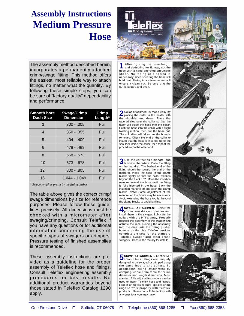
1 Af ter f igur ing the hose length and deducting for fittings, cut the
hose with a hand operated pneumatic shea r . N o tap i ng o r c l ean i ng i s necessary since shearing the hose will hold braid flaring to a minimum and will ensure a clean cut. Be sure that the cut is square and even.
2 Collar attachment is made easy by placing the collar in the holder with
the shoulder end down. Place the tapered dies over the collar so that the taper will guide the hose into the collar. Push the hose into the collar with a slight twisting motion, then pull the hose out. The split dies will fall out as the hose is removed. Check the end of the collar to insure that the hose is inserted up to the shoulder inside the collar, then repeat the procedure on the other end.
3 Use the correct size mandrel and blocks in the fixture. Place the fitting
on the mandrel. The barbed end of the fitting should be toward the end of the mandrel. Place the hose in the clamp blocks tightly so that the collar extends beyond the block 1/8”. Move the insertion mandrel toward the hose until the fitting is fully inserted in the hose. Back the insertion mandrel off and open the clamp blocks. Note: Some adjustment of the mandrel on the fixture may be necessary. Avoid extending the hose too far beyond the clamp blocks to avoid kinking.
4 SWAGE ATTACHMENT. Select the proper size dies and pusher and
install them in the swager. Lubricate the collars with dry PTFE spray. Properly position the assembly in the swager and actuate the ram, pushing the assembly into the dies until the fitting pusher bottoms on the dies. Teleflex provides complete die sets for the standard Tele f lex swager and o ther brand swagers. Consult the factory for details.
5 CRIMP ATTACHMENT. Teleflex MP smooth bore fittings are uniquely
designed to be swaged or crimped using the same inser ts and co l la rs . To accomplish f i t t ing at tachment by crimping, consult the table for crimp diameter and length dimension. Most standard fully adjustable crimpers can be used to attach Teleflex hose and fittings. Preset crimpers require special crimp rings to work properly with Teleflex products. Please consult the factory with any questions you may have.
The assembly method described herein, incorporates a permanently attached crimp/swage fitting. This method offers the easiest, most reliable way to attach fittings, no matter what the quantity. By following these simple steps, you can be sure of “factory-quality” dependability and performance. * Swage length is preset by the fitting pusher
The table above gives the correct crimp/swage dimensions by size for reference purposes. Please follow these guide-lines precisely. All dimensions must be checked wi th a micrometer af ter swaging/crimping. Consult Teleflex if you have any questions or for additional information concerning the use of specific types of swagers or crimpers. Pressure testing of finished assemblies is recommended. These assembly instructions are pro-vided as a guideline for the proper assembly of Teleflex hose and fittings. Consult Teleflex engineering assembly procedures for best resu l ts . No additional product warranties beyond those stated in Teleflex Catalog 1290 apply.
Smooth bore Dash Size
Swage/Crimp Dimension
Crimp Length*
3 .300 - .305 Full
4 .350 - .355 Full
5 .404 - .409 Full
6 .478 - .483 Full
8 .568 - .573 Full
10 .673 - .678 Full
12 .800 - .805 Full
16 1.044 - 1.049 Full
Medium Pressure Convoluted
Fittings
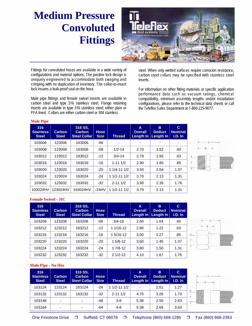
Fittings for convoluted hoses are available in a wide variety of configurations and material options. The positive lock design is uniquely engineered to accommodate both swaging and crimping with no duplication of inventory. The collar-to-insert lock insures a leak-proof seal on the hose. Male pipe fittings and female swivel inserts are available in carbon steel and type 316 stainless steel. Flange retaining inserts are available in type 316 stainless steel; either plain or PFA lined. Collars are either carbon steel or 304 stainless
steel. When only wetted surfaces require corrosion resistance, carbon steel collars may be specified with stainless steel inserts. For information on other fitting materials or specific application performance data such as vacuum ratings, chemical compatibility, minimum assembly lengths and/or installation configurations, please refer to the technical data sheets or call the Teleflex Sales Department at 1-800-225-9077.
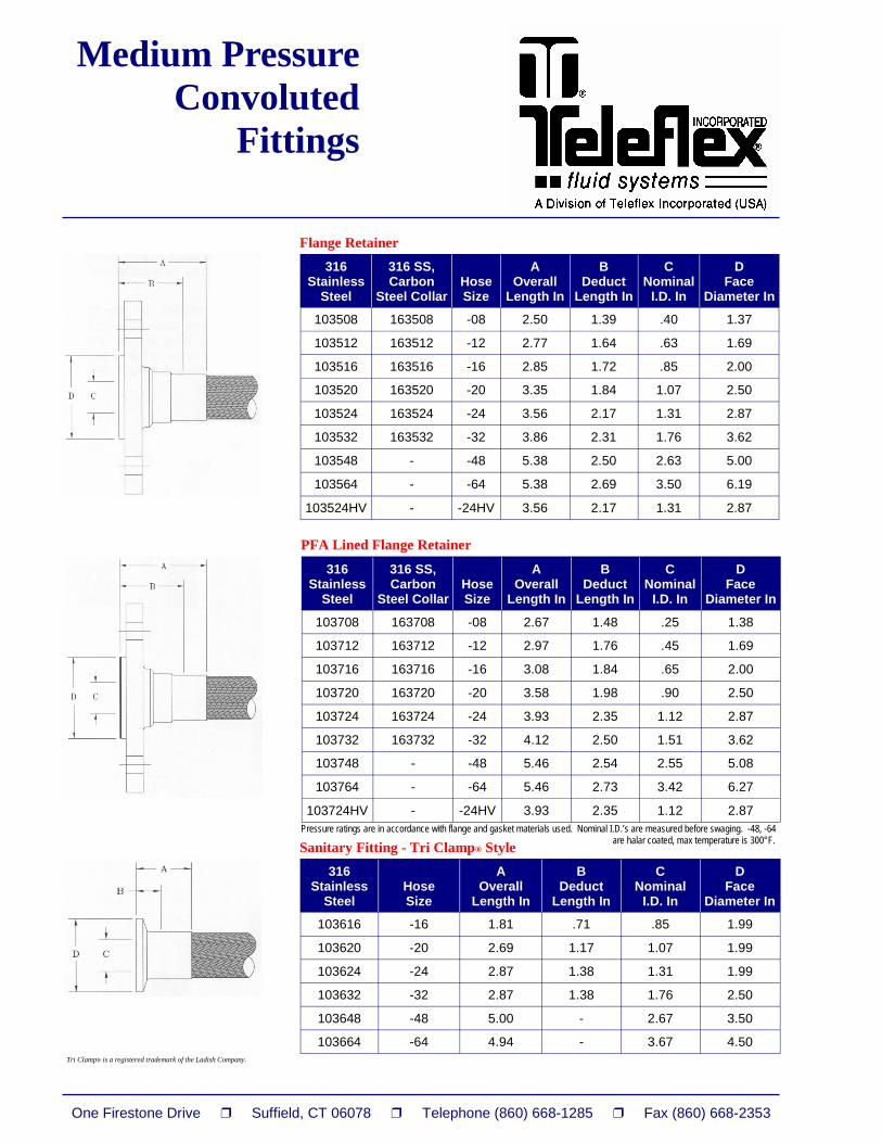
Sanitary Fitting - Tri Clamp® Style Pressure ratings are in accordance with flange and gasket materials used. Nominal I.D.’s are measured before swaging. -48, -64 are halar coated, max temperature is 300°F.
Temperature Range – 65°F to 400°F (-54°C to 204°)
Medium Pressure Convoluted
Hose (PTFE)
Teleflex Industrial Fluid Systems has brought the manufacture of tape wrapped PTFE convoluted hose to the industry fore-front. Advanced manufacturing techniques combined with strict quality control measures have combined to earn this general purpose hose product a unique place in a wide spectrum of industries and applications. Chemical plants, food processing, pharmaceutical companies, petrochemical sites, pulp and paper processors and general industrial companies of all types and sizes have relied on the performance of Teleflex Industrial Fluid Systems convoluted hose. The unique construction of tape wrapped convoluted hose combines the properties of PTFE with lighter weight and greater flexibility than any hose of comparable size. As with medium pressure smooth bore hose, tape wrapped convoluted hose is manufactured with both conductive and nonconductive inner cores depending on the demands of the application. s
Some applications require a conductive inner liner to dissipate static electrical charges. High resistivity fluids or gases at high velocity cause positive electrical charges to build on the inside of the PTFE liner. If not dissipated to the end of the hose, the charge will build until it arcs through the tube wall to the braid, causing catastrophic hose failure. To alleviate this, Teleflex manufactures a PTFE inner core with a thin conductive liner on the I.D. Other braid materials such as polyester, polypropylene, nylon and kynar are available for special applications. For information on other hose products or specific application performance data such as vacuum ratings, minimum assembly lengths and installation configurations, please refer to the technical data sheets, or call the Teleflex Sales Department at 1-800-225-9077.
Hose Number White
Hose Number
Conductive
Nominal I.D. In
Nominal O.D.
In
Operating Pressure
PSI
Burst Pressure
PSI
Bend Radius
In
Weight Lbs/ Ft
T1568-06 T1569-06 3/8 .59 1000 4000 1.00 .12
T1568-08 T1569-08 1/2 .76 1250 5000 1.50 .20
T1568-10 T1569-10 5/8 .91 1400 5600 2.00 .38
T1568-12 T1569-12 3/4 1.07 1100 4400 2.50 .33
T1568-16 T1569-16 1 1.34 1000 4000 3.00 .43
T1568-20 T1569-20 1 1/4 1.57 1000 4000 3.50 .53
T1568-24 T1569-24 1 1/2 1.81 750 3000 4.50 .65
T1568-32 T1569-32 2 2.32 500 2000 5.25 .73
T1568, T1569
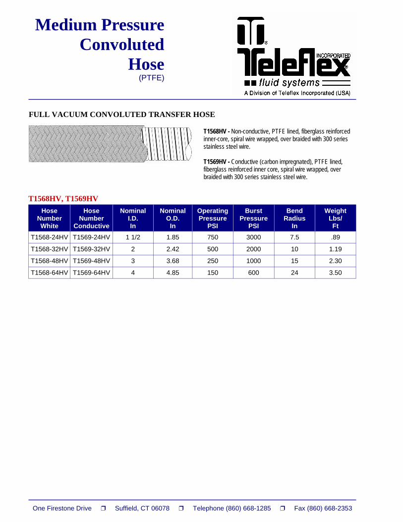
CONVOLUTED TRANSFER HOSE T1568 - Non-conductive, PTFE lined, fiberglass reinforced inner core, over braided with 300 series stainless steel wire. T1569 - Conductive (carbon impregnated), PTFE lined, fiberglass reinforced inner core, over braided with 300 series stainless steel wire.
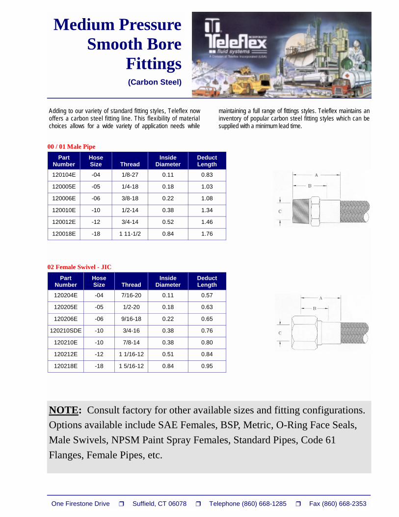
Adding to our variety of standard fitting styles, Teleflex now offers a carbon steel fitting line. This flexibility of material choices allows for a wide variety of application needs while l
maintaining a full range of fittings styles. Teleflex maintains an inventory of popular carbon steel fitting styles which can be supplied with a minimum lead time.
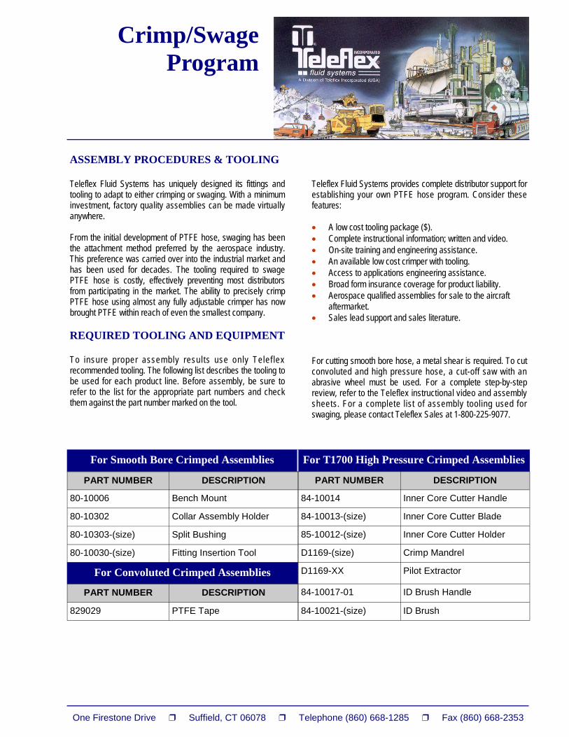
ASSEMBLY PROCEDURES & TOOLING Teleflex Fluid Systems has uniquely designed its fittings and tooling to adapt to either crimping or swaging. With a minimum investment, factory quality assemblies can be made virtually anywhere. From the initial development of PTFE hose, swaging has been the attachment method preferred by the aerospace industry. This preference was carried over into the industrial market and has been used for decades. The tooling required to swage PTFE hose is costly, effectively preventing most distributors from participating in the market. The ability to precisely crimp PTFE hose using almost any fully adjustable crimper has now brought PTFE within reach of even the smallest company. REQUIRED TOOLING AND EQUIPMENT To insure proper assembly results use only Telef lex recommended tooling. The following list describes the tooling to be used for each product line. Before assembly, be sure to refer to the list for the appropriate part numbers and check them against the part number marked on the tool.
Teleflex Fluid Systems provides complete distributor support for establishing your own PTFE hose program. Consider these features: �� A low cost tooling package ($). �� Complete instructional information; written and video. �� On-site training and engineering assistance. �� An available low cost crimper with tooling. �� Access to applications engineering assistance. �� Broad form insurance coverage for product liability. �� Aerospace qualified assemblies for sale to the aircraft
aftermarket. �� Sales lead support and sales literature. For cutting smooth bore hose, a metal shear is required. To cut convoluted and high pressure hose, a cut-off saw with an abrasive wheel must be used. For a complete step-by-step review, refer to the Teleflex instructional video and assembly sheets. For a complete list of assembly tooling used for swaging, please contact Teleflex Sales at 1-800-225-9077.
For T1700 High Pressure Crimped Assemblies For Smooth Bore Crimped Assemblies
PART NUMBER DESCRIPTION
80-10006 Bench Mount
80-10302 Collar Assembly Holder
80-10303-(size) Split Bushing
80-10030-(size) Fitting Insertion Tool
PART NUMBER DESCRIPTION
829029 PTFE Tape
For Convoluted Crimped Assemblies
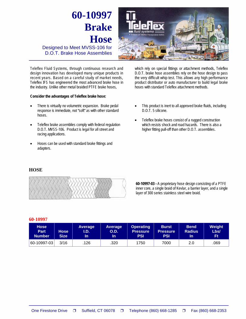
60-10997 Brake Hose
Designed to Meet MVSS-106 for D.O.T. Brake Hose Assemblies
Teleflex Fluid Systems, through continuous research and design innovation has developed many unique products in recent years. Based on a careful study of market needs, Teleflex IFS has engineered the most advanced brake hose in the industry. Unlike other metal braided PTFE brake hoses, Consider the advantages of Teleflex brake hose: �� There is virtually no volumetric expansion. Brake pedal
response is immediate, not “soft” as with other standard hoses.
�� Teleflex brake assemblies comply with federal regulation
D.O.T. MVSS-106. Product is legal for all street and racing applications.
�� Hoses can be used with standard brake fittings and
adapters.
which rely on special fittings or attachment methods, Teleflex D.O.T. brake hose assemblies rely on the hose design to pass the very difficult whip test. This allows any high performance product distributor or auto manufacturer to build legal brake hoses with standard Teleflex attachment methods. �� This product is inert to all approved brake fluids, including
D.O.T. 5 silicone. �� Teleflex brake hoses consist of a rugged construction
which resists shock and road hazards. There is also a higher fitting pull-off than other D.O.T. assemblies.
Hose Part
Number
Hose Size
Average I.D. In
Average O.D.
In
Operating Pressure
PSI
Burst Pressure
PSI
Bend Radius
In
Weight Lbs/ Ft
60-10997-03 3/16 .126 .320 1750 7000 2.0 .069
60-10997
HOSE
60-10997-03 - A proprietary hose design consisting of a PTFE inner core, a single braid of Kevlar, a barrier layer, and a single layer of 300 series stainless steel wire braid.
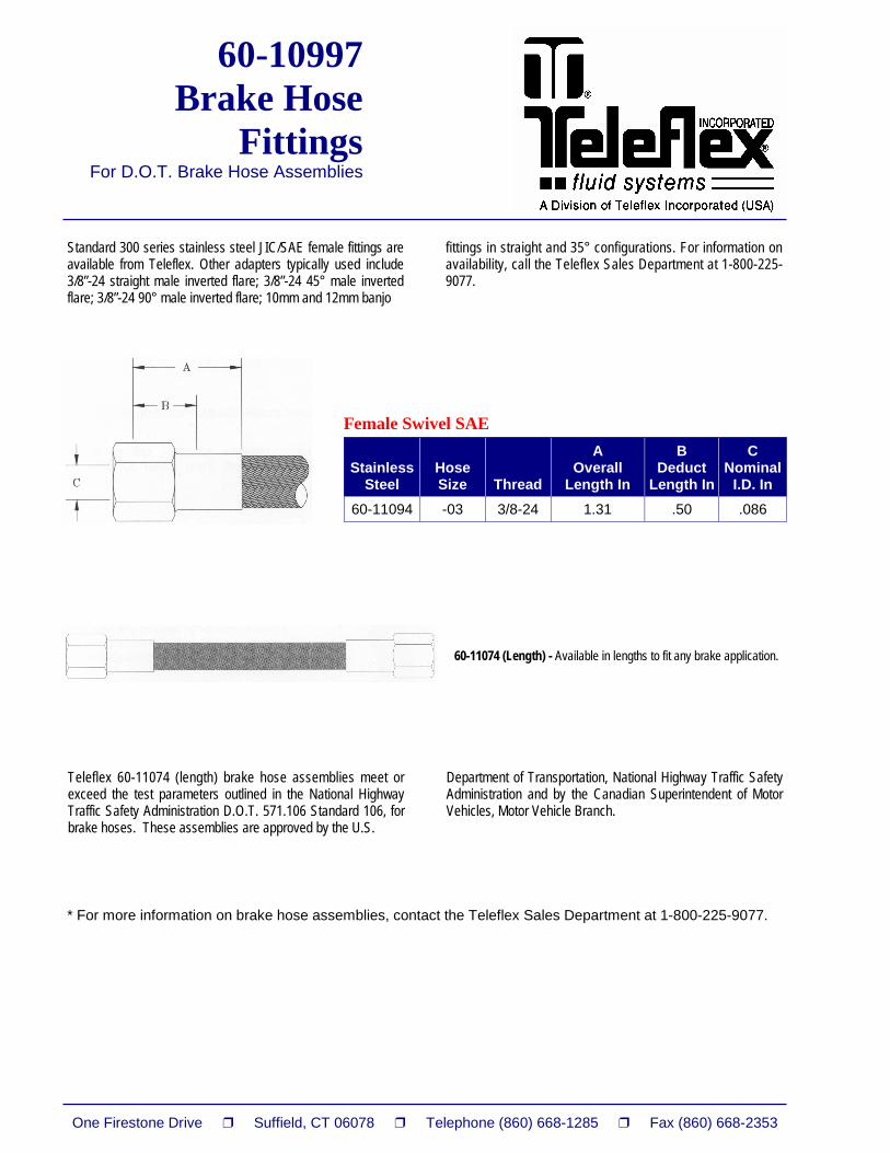
Standard 300 series stainless steel JIC/SAE female fittings are available from Teleflex. Other adapters typically used include 3/8”-24 straight male inverted flare; 3/8”-24 45° male inverted flare; 3/8”-24 90° male inverted flare; 10mm and 12mm banjo
fittings in straight and 35° configurations. For information on availability, call the Teleflex Sales Department at 1-800-225-9077.
Stainless
Steel
Hose Size
Thread
A Overall
Length In
B Deduct
Length In
C Nominal
I.D. In
60-11094 -03 3/8-24 1.31 .50 .086
Female Swivel SAE
60-11074 (Length) - Available in lengths to fit any brake application.
Teleflex 60-11074 (length) brake hose assemblies meet or exceed the test parameters outlined in the National Highway Traffic Safety Administration D.O.T. 571.106 Standard 106, for brake hoses. These assemblies are approved by the U.S.
Department of Transportation, National Highway Traffic Safety Administration and by the Canadian Superintendent of Motor Vehicles, Motor Vehicle Branch.
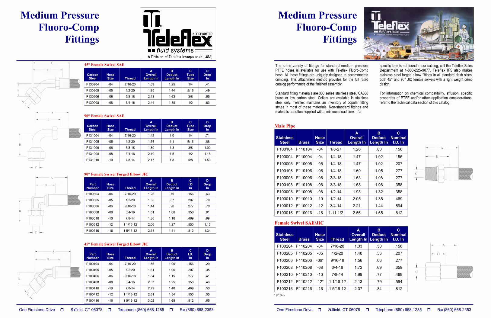
The same variety of fittings for standard medium pressure PTFE hoses is available for use with Teleflex Fluoro-Comp hose. All these fittings are uniquely designed to accommodate crimping. This attachment method provides for the full rated catalog performance of the finished assembly. Standard fitting materials are 300 series stainless steel, CA360 brass or low carbon steel. Collars are available in stainless steel only. Teleflex maintains an inventory of popular fitting styles in most of these materials. Non-standard fittings and materials are often supplied with a minimum lead time. If a
specific item is not found in our catalog, call the Teleflex Sales Department at 1-800-225-9077. Teleflex IFS also makes stainless steel forged elbow fittings in all standard dash sizes, both 45° and 90° JIC female swivels with a light weight crimp design. For information on chemical compatibility, effusion, specific properties of PTFE and/or other application considerations, refer to the technical data section of this catalog.
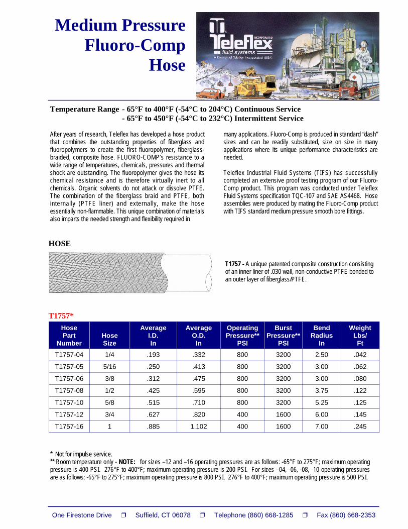
* Not for impulse service. ** Room temperature only - NOTE: for sizes –12 and –16 operating pressures are as follows: -65°F to 275°F; maximum operating pressure is 400 PSI. 276°F to 400°F; maximum operating pressure is 200 PSI. For sizes –04, -06, -08, -10 operating pressures are as follows: -65°F to 275°F; maximum operating pressure is 800 PSI. 276°F to 400°F; maximum operating pressure is 500 PSI.
After years of research, Teleflex has developed a hose product that combines the outstanding properties of fiberglass and fluoropolymers to create the first fluoropolymer, fiberglass-braided, composite hose. FLUORO-COMP’s resistance to a wide range of temperatures, chemicals, pressures and thermal shock are outstanding. The fluoropolymer gives the hose its chemical resistance and is therefore virtually inert to all chemicals. Organic solvents do not attack or dissolve PTFE. The combination of the fiberglass braid and PTFE, both internally (PTFE liner) and externally, make the hose essentially non-flammable. This unique combination of materials also imparts the needed strength and flexibility required in
many applications. Fluoro-Comp is produced in standard “dash” sizes and can be readily substituted, size on size in many applications where its unique performance characteristics are needed. Teleflex Industrial Fluid Systems (TIFS) has successfully completed an extensive proof testing program of our Fluoro-Comp product. This program was conducted under Teleflex Fluid Systems specification TQC-107 and SAE AS4468. Hose assemblies were produced by mating the Fluoro-Comp product with TIFS standard medium pressure smooth bore fittings.
HOSE
T1757 - A unique patented composite construction consisting of an inner liner of .030 wall, non-conductive PTFE bonded to an outer layer of fiberglass/PTFE.
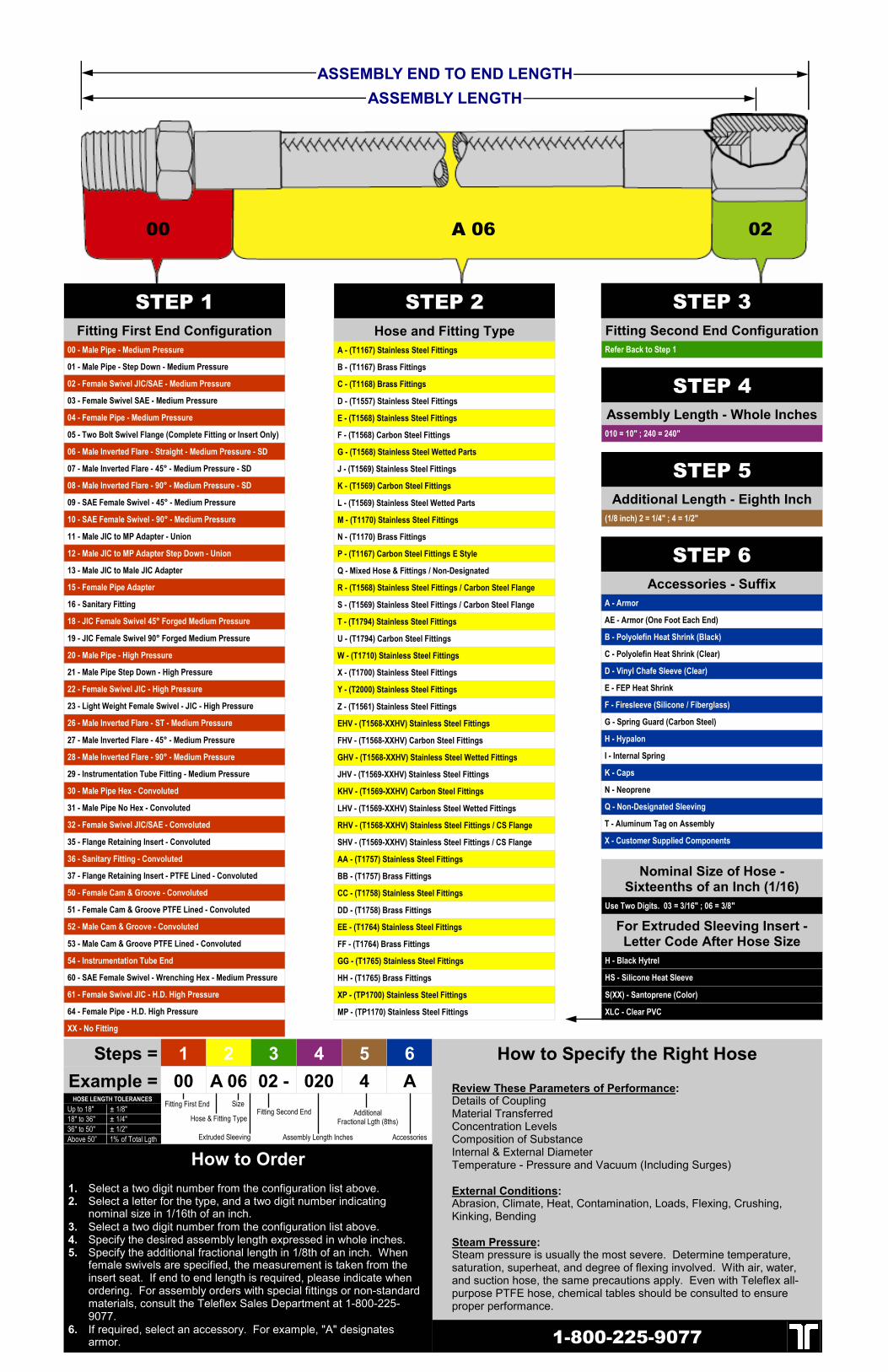
Steps = 1 2 3 4 5 6 Example = 00 A 06 02 - 020 4 A
How to Specify the Right Hose Review These Parameters of Performance: Details of Coupling Material Transferred Concentration Levels Composition of Substance Internal & External Diameter Temperature - Pressure and Vacuum (Including Surges) External Conditions: Abrasion, Climate, Heat, Contamination, Loads, Flexing, Crushing, Kinking, Bending Steam Pressure: Steam pressure is usually the most severe. Determine temperature, saturation, superheat, and degree of flexing involved. With air, water, and suction hose, the same precautions apply. Even with Teleflex all-purpose PTFE hose, chemical tables should be consulted to ensure proper performance.
How to Order 1. Select a two digit number from the configuration list above. 2. Select a letter for the type, and a two digit number indicating
nominal size in 1/16th of an inch. 3. Select a two digit number from the configuration list above. 4. Specify the desired assembly length expressed in whole inches. 5. Specify the additional fractional length in 1/8th of an inch. When
female swivels are specified, the measurement is taken from the insert seat. If end to end length is required, please indicate when ordering. For assembly orders with special fittings or non-standard materials, consult the Teleflex Sales Department at 1-800-225-9077.
6. If required, select an accessory. For example, "A" designates armor.
Hose & Fitting Type
Assembly Length Inches
Fitting Second End Size
Additional Fractional Lgth (8ths)
Accessories Extruded Sleeving
1-800-225-9077
Fitting First End Up to 18" ± 1/8" 18" to 36" ± 1/4" 36" to 50" ± 1/2" Above 50” 1% of Total Lgth
STEP 2 Fitting Second End Configuration Refer Back to Step 1
STEP 3
High Pressure Smooth Bore
Fittings
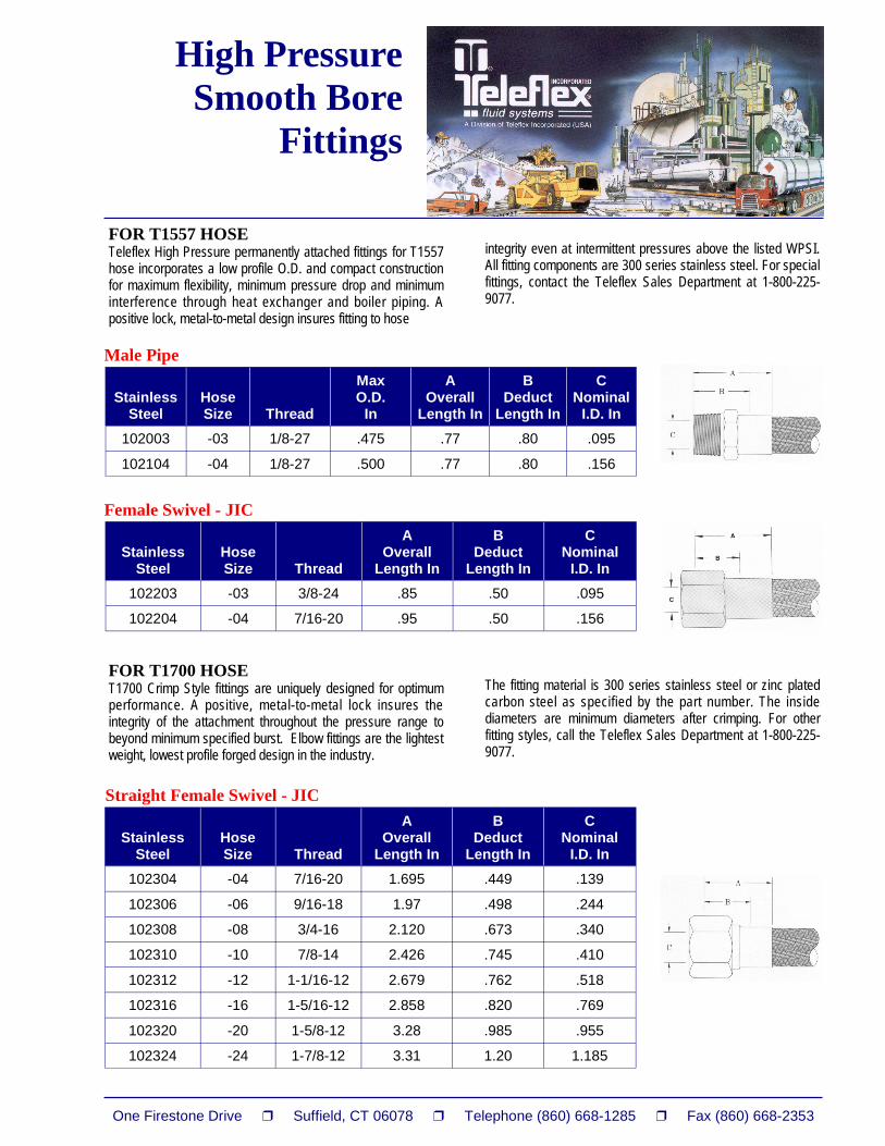
FOR T1557 HOSE Teleflex High Pressure permanently attached fittings for T1557 hose incorporates a low profile O.D. and compact construction for maximum flexibility, minimum pressure drop and minimum interference through heat exchanger and boiler piping. A positive lock, metal-to-metal design insures fitting to hose
integrity even at intermittent pressures above the listed WPSI. All fitting components are 300 series stainless steel. For special fittings, contact the Teleflex Sales Department at 1-800-225-9077.
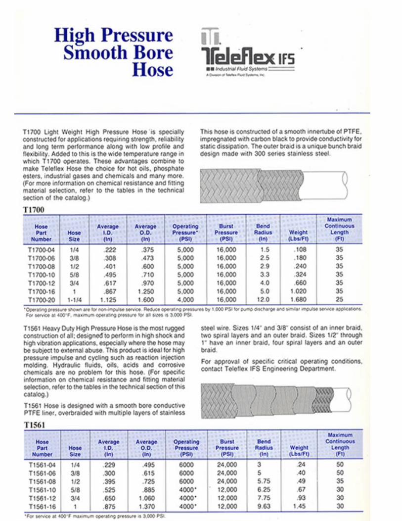
FOR T1700 HOSE T1700 Crimp Style fittings are uniquely designed for optimum performance. A positive, metal-to-metal lock insures the integrity of the attachment throughout the pressure range to beyond minimum specified burst. Elbow fittings are the lightest weight, lowest profile forged design in the industry.
The fitting material is 300 series stainless steel or zinc plated carbon steel as specified by the part number. The inside diameters are minimum diameters after crimping. For other fitting styles, call the Teleflex Sales Department at 1-800-225-9077.
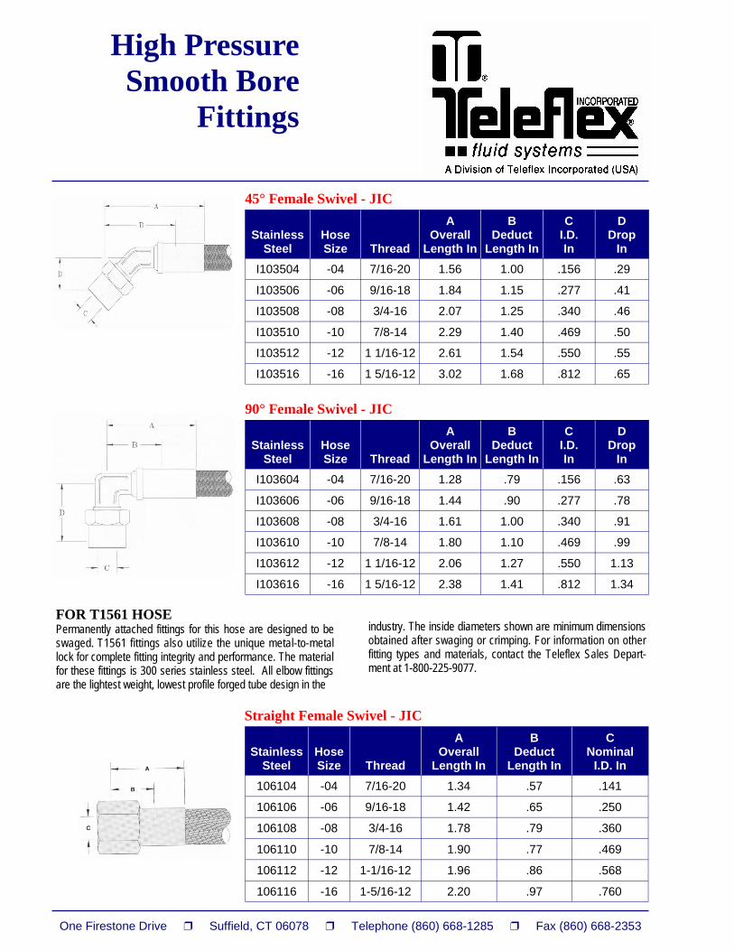
FOR T1561 HOSE Permanently attached fittings for this hose are designed to be swaged. T1561 fittings also utilize the unique metal-to-metal lock for complete fitting integrity and performance. The material for these fittings is 300 series stainless steel. All elbow fittings are the lightest weight, lowest profile forged tube design in the
industry. The inside diameters shown are minimum dimensions obtained after swaging or crimping. For information on other fitting types and materials, contact the Teleflex Sales Depart-ment at 1-800-225-9077.
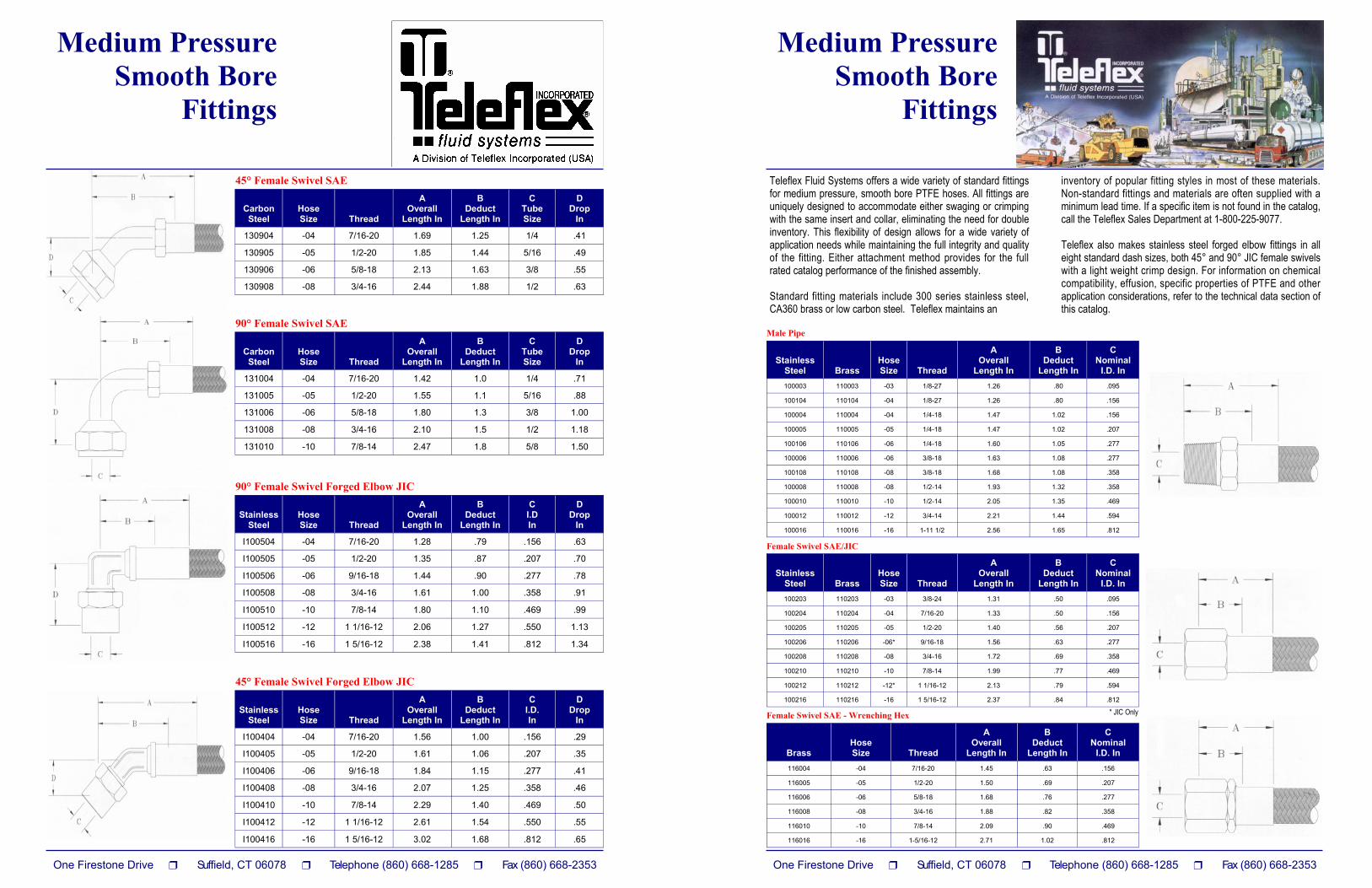
Teleflex Fluid Systems offers a wide variety of standard fittings for medium pressure, smooth bore PTFE hoses. All fittings are uniquely designed to accommodate either swaging or crimping with the same insert and collar, eliminating the need for double inventory. This flexibility of design allows for a wide variety of application needs while maintaining the full integrity and quality of the fitting. Either attachment method provides for the full rated catalog performance of the finished assembly. Standard fitting materials include 300 series stainless steel, CA360 brass or low carbon steel. Teleflex maintains an
inventory of popular fitting styles in most of these materials. Non-standard fittings and materials are often supplied with a minimum lead time. If a specific item is not found in the catalog, call the Teleflex Sales Department at 1-800-225-9077. Teleflex also makes stainless steel forged elbow fittings in all eight standard dash sizes, both 45° and 90° JIC female swivels with a light weight crimp design. For information on chemical compatibility, effusion, specific properties of PTFE and other application considerations, refer to the technical data section of this catalog.
Power Trim Fittings 300 series stainless steel fittings in size –04 with crimp style collars. Complete factory assembled power trim hose lines are available in standard 14.5 - inch length.
Power Trim Assemblies Teleflex power trim assemblies offer numerous advantages over rubber and nylon hoses for the rugged marine application. Teleflex PTFE hoses are not subject to aging or degradation from UV exposure. Only Teleflex hoses offer low volumetric expansion and long life, making Teleflex power trim hoses the most cost effective product for marine hydraulics. For information on marine fuel lines and other marine hose applications, contact the Teleflex Sales Department at 1-800-225-9077.
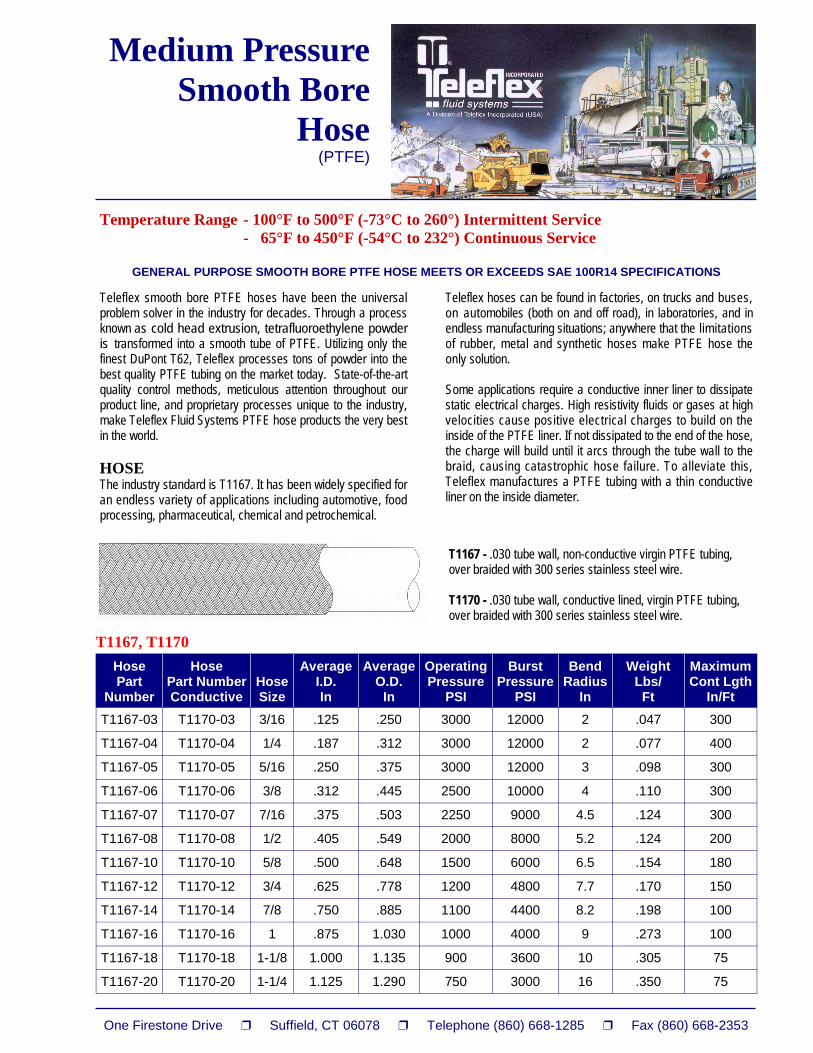
Temperature Range - 100°F to 500°F (-73°C to 260°) Intermittent Service - 65°F to 450°F (-54°C to 232°) Continuous Service
GENERAL PURPOSE SMOOTH BORE PTFE HOSE MEETS OR EXCEEDS SAE 100R14 SPECIFICATIONS
Medium Pressure Smooth Bore
Hose (PTFE)
Teleflex smooth bore PTFE hoses have been the universal problem solver in the industry for decades. Through a process known as cold head extrusion, tetrafluoroethylene powder is transformed into a smooth tube of PTFE. Utilizing only the finest DuPont T62, Teleflex processes tons of powder into the best quality PTFE tubing on the market today. State-of-the-art quality control methods, meticulous attention throughout our product line, and proprietary processes unique to the industry, make Teleflex Fluid Systems PTFE hose products the very best in the world. HOSE The industry standard is T1167. It has been widely specified for an endless variety of applications including automotive, food processing, pharmaceutical, chemical and petrochemical.
Teleflex hoses can be found in factories, on trucks and buses, on automobiles (both on and off road), in laboratories, and in endless manufacturing situations; anywhere that the limitations of rubber, metal and synthetic hoses make PTFE hose the only solution. Some applications require a conductive inner liner to dissipate static electrical charges. High resistivity fluids or gases at high velocities cause positive electrical charges to build on the inside of the PTFE liner. If not dissipated to the end of the hose, the charge will build until it arcs through the tube wall to the braid, causing catastrophic hose failure. To alleviate this, Teleflex manufactures a PTFE tubing with a thin conductive liner on the inside diameter.
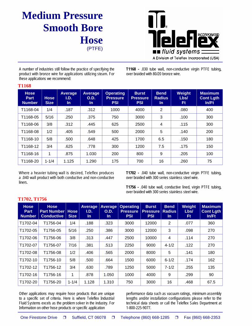
A number of industries still follow the practice of specifying the product with bronze wire for applications utilizing steam. For these applications we recommend:
T1168 - .030 tube wall, non-conductive virgin PTFE tubing, over braided with 80/20 bronze wire.
Where a heavier tubing wall is desired, Teleflex produces a .040 wall product with both conductive and non-conductive liners.
T1702 - .040 tube wall, non-conductive virgin PTFE tubing, over braided with 300 series stainless steel wire. T1756 - .040 tube wall, conductive lined, virgin PTFE tubing, over braided with 300 series stainless steel wire.
Other applications may require hose products that are unique to a specific set of criteria. Here is where Teleflex Industrial Fluid Systems excels as the problem solver in the industry. For Information on other hose products or specific application
performance data such as vacuum ratings, minimum assembly lengths and/or installation configurations please refer to the technical data sheets or call the Teleflex Sales Department at 1-800-225-9077.
SIZE Selecting the Right Hose Size With the help of this nomograph, you can easily select the correct I.D. (inches) size, desired flow rate (GPM) and recommended velocity (FPS). If you know any two factors, you can determine the third. This chart is based on the formula: Area = Flow Rate x 0.3208 Velocity Using the Nomograph: 1. Pick two known values. 2. Lay a straight edge to intersect the two values. 3. Intersection on the third vertical line is the value of that
factor. Example: A flow rate of 4 GPM is obtained through a pressure hose having an inner diameter of 1/2 inch. A line would intersect the two values and cross the velocity line at 6.5 indicating 6.5 FPS.
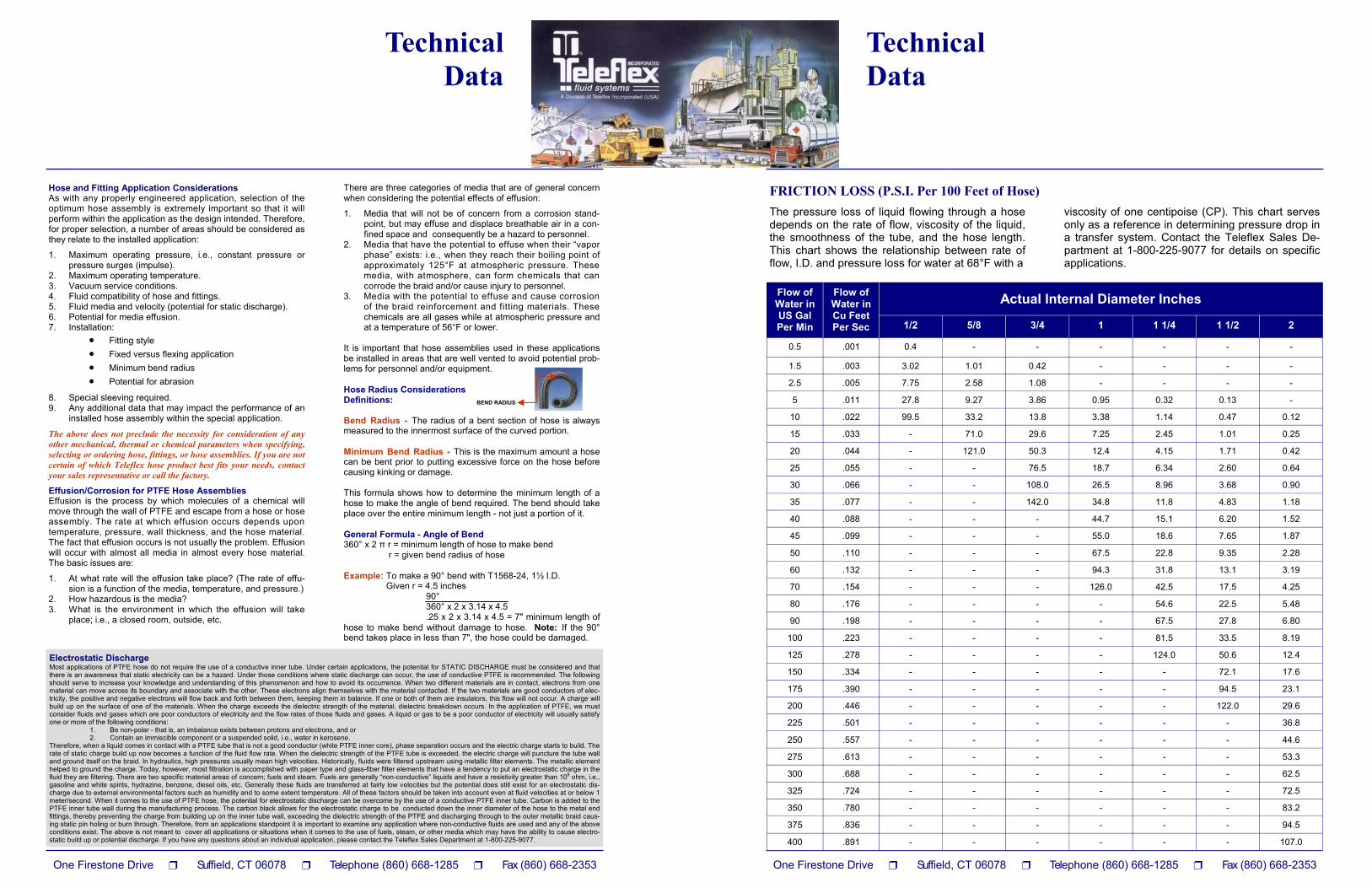
The pressure loss of liquid flowing through a hose depends on the rate of flow, viscosity of the liquid, the smoothness of the tube, and the hose length. This chart shows the relationship between rate of flow, I.D. and pressure loss for water at 68°F with a
viscosity of one centipoise (CP). This chart serves only as a reference in determining pressure drop in a transfer system. Contact the Teleflex Sales De-partment at 1-800-225-9077 for details on specific applications.
Flow of Water in US Gal Per Min
Actual Internal Diameter Inches
1/2 5/8 3/4 1 1 1/4 1 1/2 2
0.5 .001 0.4 - - - - - -
1.5 .003 3.02 1.01 0.42 - - - -
2.5 .005 7.75 2.58 1.08 - - - -
5 .011 27.8 9.27 3.86 0.95 0.32 0.13 -
10 .022 99.5 33.2 13.8 3.38 1.14 0.47 0.12
15 .033 - 71.0 29.6 7.25 2.45 1.01 0.25
20 .044 - 121.0 50.3 12.4 4.15 1.71 0.42
25 .055 - - 76.5 18.7 6.34 2.60 0.64
30 .066 - - 108.0 26.5 8.96 3.68 0.90
35 .077 - - 142.0 34.8 11.8 4.83 1.18
Flow of Water in Cu Feet Per Sec
40 .088 - - - 44.7 15.1 6.20 1.52
45 .099 - - - 55.0 18.6 7.65 1.87
50 .110 - - - 67.5 22.8 9.35 2.28
60 .132 - - - 94.3 31.8 13.1 3.19
70 .154 - - - 126.0 42.5 17.5 4.25
80 .176 - - - - 54.6 22.5 5.48
90 .198 - - - - 67.5 27.8 6.80
100 .223 - - - - 81.5 33.5 8.19
125 .278 - - - - 124.0 50.6 12.4
150 .334 - - - - - 72.1 17.6
175 .390 - - - - - 94.5 23.1
200 .446 - - - - - 122.0 29.6
225 .501 - - - - - - 36.8
250 .557 - - - - - - 44.6
275 .613 - - - - - - 53.3
300 .688 - - - - - - 62.5
325 .724 - - - - - - 72.5
350 .780 - - - - - - 83.2
375 .836 - - - - - - 94.5
400 .891 - - - - - - 107.0
Hose and Fitting Application Considerations As with any properly engineered application, selection of the optimum hose assembly is extremely important so that it will perform within the application as the design intended. Therefore, for proper selection, a number of areas should be considered as they relate to the installed application:
1. Maximum operating pressure, i.e., constant pressure or pressure surges (impulse).
2. Maximum operating temperature. 3. Vacuum service conditions. 4. Fluid compatibility of hose and fittings. 5. Fluid media and velocity (potential for static discharge). 6. Potential for media effusion. 7. Installation:
• Fitting style • Fixed versus flexing application • Minimum bend radius • Potential for abrasion
8. Special sleeving required. 9. Any additional data that may impact the performance of an
installed hose assembly within the special application.
The above does not preclude the necessity for consideration of any other mechanical, thermal or chemical parameters when specifying, selecting or ordering hose, fittings, or hose assemblies. If you are not certain of which Teleflex hose product best fits your needs, contact your sales representative or call the factory.
Effusion/Corrosion for PTFE Hose Assemblies Effusion is the process by which molecules of a chemical will move through the wall of PTFE and escape from a hose or hose assembly. The rate at which effusion occurs depends upon temperature, pressure, wall thickness, and the hose material. The fact that effusion occurs is not usually the problem. Effusion will occur with almost all media in almost every hose material. The basic issues are:
1. At what rate will the effusion take place? (The rate of effu-sion is a function of the media, temperature, and pressure.)
2. How hazardous is the media? 3. What is the environment in which the effusion will take
place; i.e., a closed room, outside, etc.
There are three categories of media that are of general concern when considering the potential effects of effusion:
1. Media that will not be of concern from a corrosion stand-point, but may effuse and displace breathable air in a con-fined space and consequently be a hazard to personnel.
2. Media that have the potential to effuse when their “vapor phase” exists: i.e., when they reach their boiling point of approximately 125°F at atmospheric pressure. These media, with atmosphere, can form chemicals that can corrode the braid and/or cause injury to personnel.
3. Media with the potential to effuse and cause corrosion of the braid reinforcement and fitting materials. These chemicals are all gases while at atmospheric pressure and at a temperature of 56°F or lower.
It is important that hose assemblies used in these applications be installed in areas that are well vented to avoid potential prob-lems for personnel and/or equipment. Hose Radius Considerations Definitions: Bend Radius - The radius of a bent section of hose is always measured to the innermost surface of the curved portion. Minimum Bend Radius - This is the maximum amount a hose can be bent prior to putting excessive force on the hose before causing kinking or damage. This formula shows how to determine the minimum length of a hose to make the angle of bend required. The bend should take place over the entire minimum length - not just a portion of it. General Formula - Angle of Bend 360° x 2 π r = minimum length of hose to make bend r = given bend radius of hose Example: To make a 90° bend with T1568-24, 1½ I.D. Given r = 4.5 inches 90° 360° x 2 x 3.14 x 4.5 .25 x 2 x 3.14 x 4.5 = 7" minimum length of hose to make bend without damage to hose. Note: If the 90° bend takes place in less than 7", the hose could be damaged.
BEND RADIUS
Electrostatic Discharge Most applications of PTFE hose do not require the use of a conductive inner tube. Under certain applications, the potential for STATIC DISCHARGE must be considered and that there is an awareness that static electricity can be a hazard. Under those conditions where static discharge can occur, the use of conductive PTFE is recommended. The following should serve to increase your knowledge and understanding of this phenomenon and how to avoid its occurrence. When two different materials are in contact, electrons from one material can move across its boundary and associate with the other. These electrons align themselves with the material contacted. If the two materials are good conductors of elec-tricity, the positive and negative electrons will flow back and forth between them, keeping them in balance. If one or both of them are insulators, this flow will not occur. A charge will build up on the surface of one of the materials. When the charge exceeds the dielectric strength of the material, dielectric breakdown occurs. In the application of PTFE, we must consider fluids and gases which are poor conductors of electricity and the flow rates of those fluids and gases. A liquid or gas to be a poor conductor of electricity will usually satisfy one or more of the following conditions:
1. Be non-polar - that is, an imbalance exists between protons and electrons, and or 2. Contain an immiscible component or a suspended solid, i.e., water in kerosene.
Therefore, when a liquid comes in contact with a PTFE tube that is not a good conductor (white PTFE inner core), phase separation occurs and the electric charge starts to build. The rate of static charge build up now becomes a function of the fluid flow rate. When the dielectric strength of the PTFE tube is exceeded, the electric charge will puncture the tube wall and ground itself on the braid. In hydraulics, high pressures usually mean high velocities. Historically, fluids were filtered upstream using metallic filter elements. The metallic element helped to ground the charge. Today, however, most filtration is accomplished with paper type and glass-fiber filter elements that have a tendency to put an electrostatic charge in the fluid they are filtering. There are two specific material areas of concern; fuels and steam. Fuels are generally “non-conductive” liquids and have a resistivity greater than 108 ohm, i.e., gasoline and white spirits, hydrazine, benzene, diesel oils, etc. Generally these fluids are transferred at fairly low velocities but the potential does still exist for an electrostatic dis-charge due to external environmental factors such as humidity and to some extent temperature. All of these factors should be taken into account even at fluid velocities at or below 1 meter/second. When it comes to the use of PTFE hose, the potential for electrostatic discharge can be overcome by the use of a conductive PTFE inner tube. Carbon is added to the PTFE inner tube wall during the manufacturing process. The carbon black allows for the electrostatic charge to be conducted down the inner diameter of the hose to the metal end fittings, thereby preventing the charge from building up on the inner tube wall, exceeding the dielectric strength of the PTFE and discharging through to the outer metallic braid caus-ing static pin holing or burn through. Therefore, from an applications standpoint it is important to examine any application where non-conductive fluids are used and any of the above conditions exist. The above is not meant to cover all applications or situations when it comes to the use of fuels, steam, or other media which may have the ability to cause electro-static build up or potential discharge. If you have any questions about an individual application, please contact the Teleflex Sales Department at 1-800-225-9077.
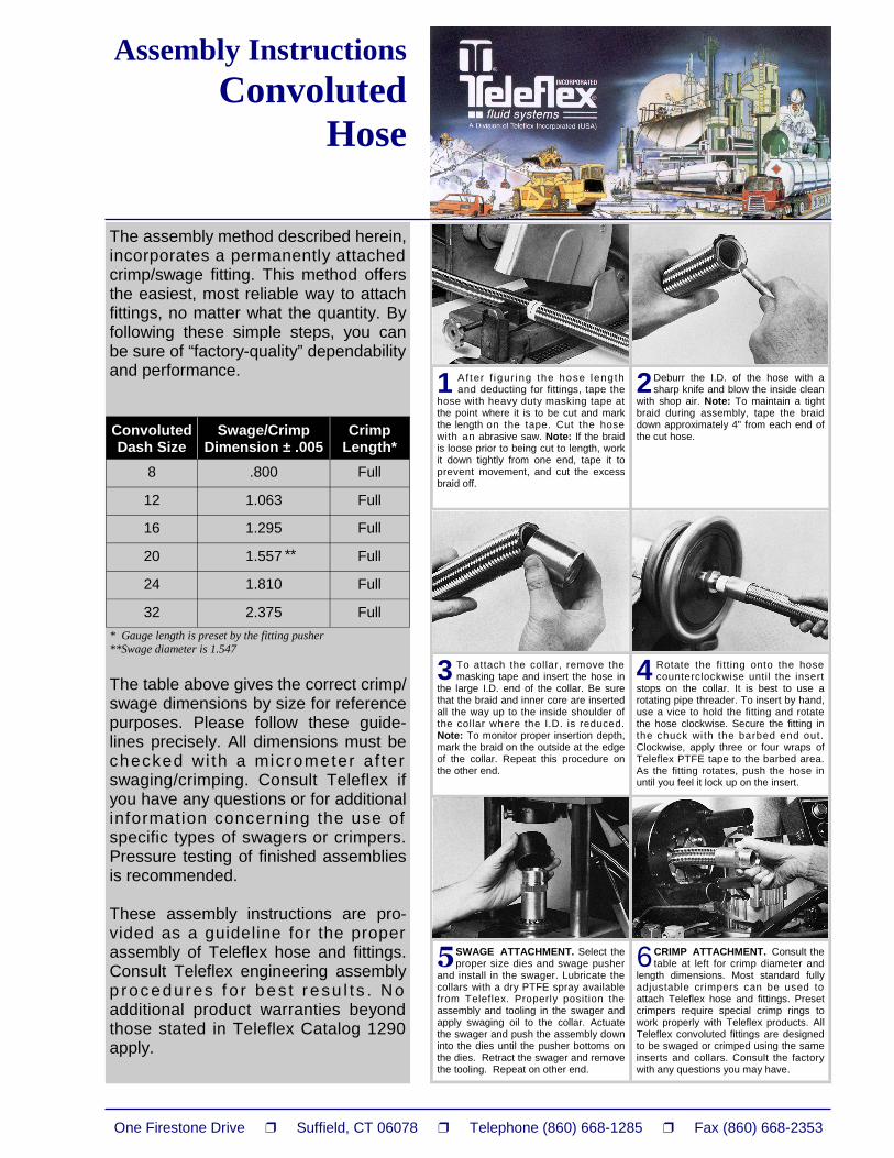
1 Af ter f igur ing the hose length and deducting for fittings, tape the
hose with heavy duty masking tape at the point where it is to be cut and mark the length on the tape. Cut the hose with an abrasive saw. Note: If the braid is loose prior to being cut to length, work it down tightly from one end, tape it to prevent movement, and cut the excess braid off.
2 Deburr the I.D. of the hose with a sharp knife and blow the inside clean
with shop air. Note: To maintain a tight braid during assembly, tape the braid down approximately 4" from each end of the cut hose.
3 To attach the collar, remove the masking tape and insert the hose in
the large I.D. end of the collar. Be sure that the braid and inner core are inserted all the way up to the inside shoulder of the collar where the I.D. is reduced. Note: To monitor proper insertion depth, mark the braid on the outside at the edge of the collar. Repeat this procedure on the other end.
4 Rotate the fitting onto the hose counterclockwise until the insert
stops on the collar. It is best to use a rotating pipe threader. To insert by hand, use a vice to hold the fitting and rotate the hose clockwise. Secure the fitting in the chuck wi th the barbed end out. Clockwise, apply three or four wraps of Teleflex PTFE tape to the barbed area. As the fitting rotates, push the hose in until you feel it lock up on the insert.
��SWAGE ATTACHMENT. Select the proper size dies and swage pusher
and install in the swager. Lubricate the collars with a dry PTFE spray available from Teleflex. Properly position the assembly and tooling in the swager and apply swaging oil to the collar. Actuate the swager and push the assembly down into the dies until the pusher bottoms on the dies. Retract the swager and remove the tooling. Repeat on other end.
6 CRIMP ATTACHMENT. Consult the table at left for crimp diameter and
length dimensions. Most standard fully adjustable crimpers can be used to attach Teleflex hose and fittings. Preset crimpers require special crimp rings to work properly with Teleflex products. All Teleflex convoluted fittings are designed to be swaged or crimped using the same inserts and collars. Consult the factory with any questions you may have.
The assembly method described herein, incorporates a permanently attached crimp/swage fitting. This method offers the easiest, most reliable way to attach fittings, no matter what the quantity. By following these simple steps, you can be sure of “factory-quality” dependability and performance. * Gauge length is preset by the fitting pusher **Swage diameter is 1.547
The table above gives the correct crimp/swage dimensions by size for reference purposes. Please follow these guide-lines precisely. All dimensions must be checked wi th a micrometer af ter swaging/crimping. Consult Teleflex if you have any questions or for additional information concerning the use of specific types of swagers or crimpers. Pressure testing of finished assemblies is recommended. These assembly instructions are pro-vided as a guideline for the proper assembly of Teleflex hose and fittings. Consult Teleflex engineering assembly p roc edu res f o r bes t r esu l ts . No additional product warranties beyond those stated in Teleflex Catalog 1290 apply.