TM 11-2586 TO31S1-2TIQ2-1 TM 11-2586 TO31S1-2TIQ2-1 DEPARTMENT OF THE ARMY TECHNICAL MANUAL DEPARTMENT OF THE AIR FORCE TECHNICAL ORDER PUBLIC ADDRESS SETS AN/TIQ-2, AN/TIQ-2A AND AN/TIQ-2B This copy is a reprint which includes current pages from Changes 7 through 10. DEPARTMENTS OF THE ARMY AND THE AIR FORCE NOVEMBER 1955
Transcript
TM 11-2586 TO31S1-2TIQ2-1
TM 11-2586
TO31S1-2TIQ2-1
D E P A R T M E N T O F T H E A R M Y
T E C H N I C A L M A N U A L
D E P A R T M E N T O F T H E A I R
F O R C E T E C H N I C A L O R D E R
P U B L I C
A D D R E S S S E T S
A N / T I Q - 2 , A N / T I Q - 2 A
A N D A N / T I Q - 2 B
T h i s c o p y i s a r e p r i n t w h i c h i n c l u d e s c u r r e n t
p a g e s f r o m C h a n g e s 7 t h r o u g h 1 0 .
DEPARTMENTS OF THE ARMY AND THE AIR FORCE
N O V E M B E R 1 9 5 5
WARNING
DANGEROUS VOLTAGES EXIST IN THIS EQUIPMENT
Be careful when working, on the 400-volt plate and power supplycircuits, or on the 115-230-volt ac line connections.
DON’T TAKE CHANCES!
Changes in Force: C 7, C 8, C 9, and C 10
CHANGES
No. 10
TM 11-2586T031S1-2TIQ2-1
C 10HEADQUARTERS,
DEPARTMENT OF THE ARMYAND THE AIR FORCE
WASHINGTON, DC, 29 August, 1977
Operator's, Organizational, DS, GS, and Depot MaintenanceManual Including Repair Parts and Special Tools list
PUBLIC ADDRESS SETS AN/TIQ-2 (NSN 5830-00-164-6618),AN/TI-2A (NSN 5830-00-1 644622), AND AN/TIQ-2B
(NSN 5830-00-690-9705).
TM 11-2586/T031S1-2TIQ2-1, 29 November 1955, is changed asfollows:
Title of manual is changed as shown above.Page preceding page 1. Add radiation warning.
Radium Markers Ra 226 0.4uCi 9905-00-252-3748
Radiation Hazard Information: The following radiation hazard in-formation must be read and understood by all personnel beforeoperating or repairing the Public Address Sets AN/TIQ-2, AN/TIQ-2A, and AN/TIQ-2B. Hazardous radioactive materials arepresent in the above listed component of the Public Address SetsAN/TIQ-2, AN/TIQ-2A, and AN/TIQ-2B.
The components are potentially hazardous when broken. See qual-ified medical personnel and the local Radiological Protection Officer(RPO) immediately if you are exposed to or cut by broken compo-nents. First aid instructions are contained in TB 43-0122, and AR755-15.
1
NEVER place radioactive components in your pocket. Use extremecare NOT to break radioactive components while handling them.
NEVER remove radioactive components from cartons until you areready to use them.
If any of these components are broken, notify the local RPO im-mediately. The RPO will survey the immediate area for radiologicalcontamination and will supervise the removal of broken compo-nents. The above listed radioactive components will not be repairedor disassembled.
Disposal of broken, unserviceable, or unwanted radioactive compo-nents will be accomplished in accordance with the instructions inAR 755-15.
Page 41, “FSN” column, line 9 Delete 5905-226-9441 and substi-tute 5905-81-2448.
“Description” column, line 18: Delete 81350 and substi-t u t e 8 1 3 4 9 .
“Description” column, line 19: Delete RY3A1FK504Cand substitute RV4NAYSK504C.
NG: State AG (3); Unite-Same as Active Army except allowance is one copyper unit.
USAR: None
For explanation of abbreviations used see AR 310-50.
II
ARTIFICIAL RESPIRATIONGENERAL PRINCIPLES1. Seconds count! Begin at once! Don’t take time to move the victimunless you must. Don’t loosen clothes, apply stimulants or try to warmthe victim. Start resuscitation ! Get air in the lungs! You may save a life !2. Place the victim’s body in a prone position, so that any fluids willdrain from the respiratory passages. The head should be extended andturned sideward never flexed forward; the chin shouldn’t sag, since ob-struction of the respiratory passages may occur.3. Remove any froth or debris from the mouth with your fingers. Drawthe victim’s tongue forward.4. Begin artificial respiration. Continue it rhythmically and without anyinterruption until natural breathing starts or the victim is pronounceddead. Try to keep the rhythm smooth. Split-second timing is not abso-lutely essential.5. When the victim starts breathing, or when additional help is availableloosen the clothing; remove it, if it’s wet; keep the victim warm. Shockshould receive adequate attention. Don’t interrupt the rhythmical arti-ficial technique for these measures. Do them only when you have help orwhen natural breathing has started.6. When the victim is breathing, adjust your timing to assist him. Don’tfight his efforts to breathe. Synchronize your efforts with his. After re-suscitation, keep him lying down until seen by a physician or until re-covery seems certain.7. Don’t wait for mechanical resuscitation! If an approved model is avail.able, use it, but, since mechanical resuscitators are only slightly moreeffective than properly performed “push-pull” manual technique, neverdelay manual resuscitation for it.BACK-PRESSURE ARM LIFT METHOD1. Position of Victim. Place the victim in the prone (facedown) position.Bend his elbows; place one hand upon the other. Turn his face to oneside, placing his cheek upon his hands.2. Position of Operator. Kneel on your left or right knee, at the victim’shead, facing him. Your knee should be at the side of the victim’s headclose to his forearm, your foot should be near his elbow. Kneel on bothknees if you find it more comfortable, with one knee on each side of thehead. Place your hands on the flat of the victim’s back so that their heelsare just below the lower tip of his shoulder blades. With the tip of yourthumbs touching spread your fingers downward and outward. (See A).
3. Compression Phase. Rock forward until your arms are approximatelyvertical and allow the weight of the upper part of your body to exert aslow, steady, even, downward pressure upon your hands. This forces airout of the lungs. Keep your elbows straight and press almost directlydownward on the back. (See B),4. Expansion Phase. Release the pressure, avoid any finish thrust, andcommence to rock backward slowly. Place your arms upon the victim’sarms just above the elbows, and draw his arms upward and toward you.Apply just enough lift to feel resistance and tension at the victim’sshoulders. Don’t bend your elbows. As you rock backward, the victim’sarms will be drawn toward you. (The arm lift expands the chest by pull-ing on the chest muscles, arching the back and relieving the weight onthe chest. ) Drop the arms gently to the ground or floor. This completesthe cycle. (See C and D). Now, repeat the cycle.5. Cycle Timing and Rhythm. Repeat the cycle 10 to 12 times per minute.Use a steady uniform rate of Press, Release, Lift, Release. Longer countsof about equal length should be given to the “Press” and “Lift” steps ofthe compression and expansion phases. Make the “Release” periods ofminimum duration.6. Changing Position or Operator.
(a) Remember that You can use either or both knees or can shiftknees during the procedure, provided you don’t break the rhythm. Ob-serve how you rock forward with the back-pressure and backward withthe arm-lift. The rocking motion helps to sustain the rhythm and addsto the ease of operation.
(b) If you tire and another person is available, you can “take turns,”Be careful not to break the rhythm in changing. Move to one side and letyour replacement come in from the other side. Your replacement beginsthe “Press-Release” after one of the “Lift-Release” phases, as you moveaway.
TM AR-I
III
Changes in force: C 7, C 8, and C 9
TM 11-2586
C 9
CHANGE HEADQUARTERSDEPARTMENT OF THE ARMY
No. 9 WASHINGTON, D.C., 19 February 1974
Operator’s, Organizational, Direct Support, General Support,
and Depot Maintenance Manual
Including Repair Parts and Special Tools Lists
PUBLIC ADDRESS SETS AN/TlQ-2,
A N / T I Q - 2 A , A N D A N / T I Q - 2 B
TM 11-2586/TO 31S1-2T1Q2-1, 29 November 1955, is changed asfollows:
Page 3, paragraph 1. Delete subparagraph c.
Paragraph 1.1. Delete paragraph 1.1 and substitute:
1-1. Indexes of Publications
a. DA Pam 310-4. Refer to the latest issue of DA Pam 310-4to determine whether there are new editions, changes, or addi-tional publications pertaining to the equipment.
b. DA Pam 310-7. Refer to DA Pam 310-7 to determinewhether there are modification work orders (MWO’s) pertainingto the equipment.
Paragraph 2. Delete paragraph 2 and substitute:
2. Forms and Records
a. Reports of Maintenance and Unsatisfactory Equipment.Maintenance forms, records, and reports which are to be usedby maintenance personnel at all maintenance levels are listed inand prescribed by TM 38-750.
b. Report of Packaging and Handling Deficiencies. Fill outand forward DD Form 6 (Report of Packaging and HandlingDeficiencies) as prescribed in AR 700-58 (Army)/NAVSUP PUB378 (Navy)/AFR 71-4 (Air Force)/and MCO P4030.29 (MarineCorps), and DSAR 4145.8.
c. Discrepancy in Shipment Report (DISREP) (SF 361). Fillout and forward Discrepancy in Shipment Report (DISREP) (SF
1
361) as prescribed in AR 55-38 (Army)/NAVSUPINST 4610.33/AFM 75-18/MCOP4610.19A (Marine Corps), and DSAR 4500.15.
2.1. Reporting Equipment Publication Improvements
The Reporting of errors, omissions, and recommendations for improving this publicationby the individual user is encouraged. Reports should be submitted on DA Form 2028,Recommended Changes to Publications, and forwarded direct to Commander, US ArmyElectronics Command, ATTN: AMSEL-MA-C, Fort Monmouth, NJ 07703.
Page 9, paragraph 7. Change paragraph heading "Table of Components" to read"Components and Dimensions."
Page 10. After paragraph 7 add:
7.1. Items Comprising an Operable Equipment
FSN Qty Nomenclature, part No. and mfr code Usableon
codeNOTE
The part number is followed by the applicable5-digit Federal supply code for manufacturers(FSCM) identified in SB 708-42 and used toidentify manufacturer, distributor, orGovernment agency; etc.
NOTENumber 1 in the usable-on code column refersto AN/TIQ-2; number 2 refers to AN/TIQ-2A;number 3 refers to AN/TIQ-2B
7740-222-3472 2 Album, Record, Disk: 5-10; 85351 1,2,37740-222-3471 1 Album, Record, Disk: 5-12; 85351 1,2,35830-164-6626 1 Amplifier, Audio frequency AM-20, A, B/TIQ-2; 1,2,3
71-3023 (NX); 81349.5995-163-0017 1 Cable Assembly, Special Purpose, Electrical 1,2,3
Page 122, appendix B. Delete appendix B and substitute:
APPENDIX B
BASIC ISSUE ITEMS LIST (BIIL) AND ITEMS TROOPINSTALLED OR AUTHORIZED LIST (ITIAL)
Section I. INTRODUCTIONB-1. ScopeThis appendix lists only basic issue items required by the crew/operator for installation,operation, and maintenance of Public Address Sets AN/TIQ-2, AN/TIQ-2A, and AN/TIQ-2B.
3
B-2. General
These basic issue items and items troop installed or authorizedlists are divided into the following sections:
a. Basic Issue Items List-Section II. A list, in alphabeticalsequence, of items which are furnished with, and which must beturned in with the end item.
b. Items Troop Installed or Authorized List - Section II. Notapplicable.
B-3. Explanation of Columns
The following provides an explanation of columns found in thetabular listings:
a. Illustration. This column is divided as follows:(1) Figure Number. Indicates the figure number of the il-
lustration in which the item is shown.
(2) item Number. Not applicable.
b. Federal Stock Number. Indicates the Federal stock numberassigned to the item which will be used for requisitioning pur-poses.
c. Part Number. Indicates the primary number used by themanufacturer (individual, company, firm, corporation, or gov-ernment activity), which controls the design and characteristicsof the item by means of its engineering drawings, specificationsstandards, and inspection “requirements, to identify an item orrange of items.
d. Federal Supply Code for Manufacturer (FSCM). T h eFSCM is a 5-digit numeric code used to identify the manufac-turer, distributor, or Government agency; etc., and is identifiedin SB 708-42.
e. Description. Indicates the Federal item name and aminimum description required to identify the item.
f. Unit of Measure (U/M). Indicates the standard of basicquantity of the listed item as used in performing the actualmaintenance function. This measure is expressed by a two-character alphabetical abbreviation, (e. g., ea, in., pr; etc.).When the unit of measure differs from the unit of issue, thelowest unit of issue that will satisfy the required units of meas-ure will be requisitioned.
g. Quantity Furnished with Equipment (Basic Issue ItemsOnly). Indicates the quantity of the basic issue item furnishedwith the equipment.
4
Quantity Authorized (Items Troop Installed or Authorized Only). Not applicable.
B-4. Special Information
Usable-on codes are included in column 5. Uncoded items are applicable to all models.Identification of the usable-on codes are as follows:
Code Used on
1 AN/TIQ-22 AN/TIQ-2A3 AN/TIQ-2B
SECTION II. BASIC ISSUE ITEMS LIST
(1) (2) (3) (4) (5) (6) (7)Illustration Federal Unit Qty
stock Part of furn(A)FigNo
(B)ItemNo
number number FSCM DescriptionUsable
on code
meas withequip
3 5830-404-7266 SC-DL-22232 80063 CASE: CY-37/ 1,2,3 ea 1TIQ-2; CY-37A/TIQ-2
3 5830-503-1641 SC-DL-12714 80063 CASE: CY38/ 1 ea 3TIQ-2
3 5830-503-1641 SC-DL-12714 80063 CASE: CY38/ 2,3 ea 2TIQ-2
5865-164-7265 SC-D-5978 80063 MICROPHONE 1,2,3 ea 2COVER:M-367.
By Order of the Secretary of the Army:
CREIGHTON W. ABRAMSGeneral, United States Army
Official: Chief of StaffVERNE L. BOWERSMajor General, United States ArmyThe Adjutant General
PUBLIC ADDRESS SETS AN/TIQ-2,AN/TIQ-2A, AND AN/TIQ-2B
TM 11-2586,29 November 1955, is changed as follows:
The title of the manual is changed as shown above.
Page 110, paragraph 100.7c, chart, step 2 (page 23 of C7).“Procedure” column. Add item j after item i.
j. Connect a 100-ohm resistor across the CARBON MICRO-PHONE input jack. Set the AM-20(*)/TIQ-2 RADIO-C MICswitch to C. MIC. Note and record the TS-723/U meter indi-cations.
“Performance Standard” column. Add item j after item i.
j. The TS-723A/U meter should not indicate more than 2.25Volta.
Page 117, paragraph 108 (page 30 of C7), second line. Change“(para 100.8, step 2)” to (para 100.7, step 2).
Paragraph 108.3 (page 31 of C7). Delete second sentence andsubstitute: The vacuum tube voltmeter should indicate between aminimum of 3.0 volts and a maximum of 4.1 volts.
Page 122. (Page 34 of C7). Change APPENDIX I to: AP-PENDIX A.
“This change supersedes TM 11-5830-206-20P, 20 November 1964, and TM 11-5830206-35P, 19 November 1964.
TAGO 7472B 1
Delete appendix II and substitute new appendix B:
APPENDIX B
BASIC ISSUE ITEMS
Section I. INTRODUCTION
B-1. GeneralThis appendix lists items for Public Address Sets AN/TIQ-2,
AN/TIQ-2A, and AN/TIQ-2B, the component items comprisingit, and the items which accompany it, or are required for installa-tion, operation, or operator’s maintenance.
B-2. Explanation of ColumnsAn explanation of the columns in section II is given below.a. Source, Maintenance, and Recoverability Codes, Column 1.
(1)
codeP
A
(2)
(3)
2
Source code, column 1a. The selection status and sourcefor the listed item is noted here. The source code usedis:
ExplanationApplies to repair parts which are stocked in or supplied from the
GSA/DSA, or Army supply system, and authorized for use atindicated maintenance categories.
Applies to assemblies that are not procured or stocked as suchbut are made up of two or more units, each of which carryindividual stock numbers and descriptions and are procuredand stocked and can be assembled by units at indicated mainte-nance categories.
Maintenance code, column 1b. The lowest category ofmaintenance authorized to install the listed item is notedhere. The maintenance code used is as follows:
Recoverability code, column 1c, The information in thiscolumn indicates whether unserviceable items should bereturned for recovery or salvage. Recoverability codesand their explanations are as follows:
Note. When no code is indicated in the recoverability column,the part will be considered expendable.
Code ExplanationR Applies to repair parts and assemblies that are economically
repairable at DSU and GSU activities and are normally fur-nished by supply on an exchange basis.
b. Federal Stock Number, Column 2. The Federal stock num-ber for the item is indicated in this column.
c. Description, Column 3. The Federal item name, a five-digitmanufacturer’s code, a part number, and when required, the modeldesignator (*), which indicates different models of the end equip-ment, are included in this column.
d. Unit of Issue, Column 4. The unit used as a basis of issuee.g. ea, pr, ft, yd, etc) is noted in this column.
e. Quantity Incorporated in Unit Pack, Column 5. Not used,
f. Quantity Incorporated in Unit, Column 6. The total quantityof the item used in the equipment is given in this column.
g. Quantity Authorized, Column 7. The total quantity of anitem required to be on hand and necessary for the operation andmaintenance of the equipment is given in ‘this column.
h. Illustration, Column 8.(1) Figure number, column 8a. The number of the illustra-
tion in which the item is shown is indicated in thiscolumn.
This manual contains a list of repair parts required for the per-formance of organizational maintenance and a list covering thecorresponding requirements for direct support, general support,and depot maintenance for Public Address Set AN/TIQ-2, AN/TIQ-2A, and AN/TIQ-2B.
Note. No special tools, test, and support equipment are required for theAN/TIQ-2, AN/TIQ-2A, and AN/TIQ-2B.
D-2. Explanation of SectionsThis repair parts list is divided into four principal parts:a. Prescribed Load Allowance List (PLA)- Section II. T h e
PLA is a consolidated listing of repair parts allocated for initialstockage at organizational maintenance. This is a mandatoryminimum stockage allowance.
b. Repair Parts for Organizational Maintenance-Section III.Repair parts authorized for organizational maintenance is in-cluded in this section.
c. Repair Parts for Direct Support, General Support, and DepotMaintenance-Section IV. This chart lists repair parts authorizedfor maintenance performance at direct support, general supportand depot.
d. Federal Stock Number Cross-Reference Index-Section IV.This is a cross-reference index of Federal stock numbers to illus-trations by figure and item number.
D-3. Explanation of ColumnsAn explanation of the columns in sections II through IV is given
below.a. Source, Maintenance, and Recoverability Codes, Column 1,
Sections III and IV.
7
(1)
CodeP
A
X2
(2)
CodeC
O
F
( 3 )
CodeR
Source code, column la. The selection status and sourcefor the listed item is noted here. Source codes and theirexplanations are as follows:
ExplanationApplies to repair parts that are stocked in or supplied from the
GSA/DSA, or Army supply system, and authorized for use atindicated maintenance categories.
Applies to assemblies that are not procured or stocked as such butare made up of two or more units, each of which carry in-dividual stock numbers and descriptions and are procured andstacked and can be assembled by units at indicated maintenancecategories
Applies to repair parts which are not stocked. The indicatedmaintenance category requiring such repair parts will attemptto obtain them through cannibalization; if not obtainablethrough cannibalization, such repair parts will be requisitionedwith supporting justification through normal supply channels.
Maintenance code, column 1b. The lowest category ofmaintenance authorized to install the listed item is notedhere.
ExplanationOperator/CrewOrganizational MaintenanceDirect Support Maintenance
Recoverability code, column 1c. The information in thiscolumn indicates whether unserviceable items should bereturned for recovery or salvage. Recoverability codesand their explanations are as follows:
Note. When no code is indicated in the recoverability column,the part will be considered expendable.
ExplanationApplies to repair parts and assemblies which are economically
repairable at DSU and GSU activities and normally are fur-nished by supply on an exchange basis.
b. Federal Stock Number, Column 1, Section II; Column 2,Section III and IV. The Federal stock number for the item is in-dicated in this column.
c. Description, Column 2, Section II; Column 3, Sections IIIand IV. The model designator, Federal item name, a five-digitmanufacturer’s code, and a part number are included in this col-umn. The designator (*) indicates the different models of the
8 AGO 7472B
end equipment, For subsequent appearances of the same item,the manufacturer’s code and part number are omitted.
d. Unit of Issue, Column 4, Sections III and IV. The unit usedas basis of issue (e.g. ea, pr, ft, yd, etc) is noted in this column.
e. Quantity Incorporated in Unit Pack, Column 4, Section II;Column 5, Sections III and IV. Not used.
f. Quantity Incorporated in Unit, Column 6, Sections III andIV. The quantity of repair parts in an assembly is given in thiscolumn.
g. Maintenance Allowance, Column 3, Section II; Column 7,Sections III and IV.
(1)
(2)
(3)
AGO 7472B
The allowance columns are divided into subcolumns. Thetotal quantity of items authorized for the number ofequipment supported is indicated in each subcolumn op-posite the first appearance of each item. Subsequentappearances of the same item will have no entry in theallowance columns but will have a reference, in the de-scription column, to the first appearance of the item.Items authorized for use as required but not for initialstockage are identified with an asterisk (*) in the allow-ance column.The quantitative allowances for organizational categoryof maintenance represents one initial prescribed load fora 15-day period for the number of equipments supported.Units and organizations authorized additional prescribedloads will multiply the number of prescribed loads au-thorized by the quantity of repair parts reflected in theappropriate density column to obtain the total quantityof repair parts authorized.Subsequent changes to organizaitonal allowances will belimited as follows: No change in the range of items isauthorized. If additional items are considered necessary,recommendation should be forwarded to CommandingGeneral, U. S. Army Electronics Command, ATTN:AMSEL-MR-NMP-CM, Fort Monmouth, N. J. 07703,for exception or revision to the allowance list. Revisionsto the range of items authorized will be made by the USAECOM National Maintenance Point based upon engineer-ing experience, demand data, or TAERS information.
9
(4) The quantitative allowances for DS/GS categories ofmaintenance will represent initial stockage for a 30-dayperiod for the number of equipments supported.
h. One-Year Allowances Per 100 Equipments/ContingencyPlanning Purposes, Column 8, Section IV. Opposite the first ap-pearance of each item, the total quantity required for distributionand contingency planning purposes is indicated. The range ofitems indicates total quantities of all authorized items required toprovide for adequate support of 100 equipments for one year.
i. Illustration, Column 8, Section III; Column 10, Section IV.
(1) Figure number, column 8a and 10a. The number of theillustration in which the item is shown is indicated inthis column.
(2) Item or symbol number, column 8b and 10b. The calloutnumber used to reference the item in the illustration isindicated in this column.
j. Depot Maintenance Allowance Per 100 Equipments, Column9, Section IV. This column indicates the total quantity of eachitem authorized depot maintenance for 100 equipments. Subse-quent appearances of the same item will have no entry in thiscolumn, but will have a reference in the description column to thefirst apparance of the item.
D-4. Location of Repair Partsa. When the Federal stock number is unknown follow the pro-
cedures given in (1) through (4) below.
(1) Locate the appropriate appendix of the repair parts list.
(2) If the item or symbol number is available, locate the itemby scrutiny of columns 8b and/or 10b of the repair parts list.
(3) If the item, symbol, and figure number is not knowncheck the description column (column 3) in the repairparts list to locate the part. The parts in this column arearranged in alphabetical order.
(4) Locate the applicable illustration in this manual and notethe figure number and item number. Use the repair partslisting and locate the figure number and item number asnoted on the illustration.
10
b. When the Federal stock number is known, use the repairpart listing to find the repair part and the figure and item num-bers as noted in the Index of Federal stock numbers.
D-5. Federal Supply CodesThis paragraph lists the Federal supply code and the associated
Manufacturer’s nameAmphenol-Borg Electronics CorpInternational Hardware Co of Canada LtdUnited-Carr Fastener Co of Canada LtdGeneral Microwave CorpCanfield, H.O. Co of Indiana IncMotorola IncElastic Stop Nut Corp of America Fastener DivisionHeintzman and Co LtdParker Kalon Div of General American Transportation CorpPyle-National CoSprague Electric CoStanley WorksUnited-Carr Fastener CorpAstatic CorpBussmann Mfg Division of McGraw-Edison CoITT Cannon Electric IncCardwell Mfg Co IncCinch Mfg Co and Howard B. Jones DivDialight CorpElastic Stop Nut Corp of AmericaAmerican Microphone Co Division of Electro-Voice IncGeneral Industries CoThe Johnson Rubber CoKurz-Kasch IncMueller Electric CoPatton MacGuyer CoShakeproof Division of Illinois Tool Works IncTinnerman Products IncArmy Electronics Command Procurement and Production Di-
tion Div Directorate of Logictic Services DSAHerman H. Smith IncUnited States Rubber International CoBasic Refractories IncAir Force-Navy Aeronautical Specifications, Promulgated by
Aeronautical Standards Group
11
87771 LTV University Division Ling-Temco-Vought Inc89373 United States Rubber Co; United States Rubber Tire Co94988 Chatham Electronics Div of Tung-Sol Electric Inc96739 Pacific Transducer Corp96806 Military Standard Promulgated by Standardization Div Di-
rectorate of Logistic Services DSA97539 Apm-Hexseal Corp97983 Litton Systems Inc Westrex Communications Div
12 AGO 7472B
GROUP VIII
13
LOGSA
5960-188-0883
LOGSA
5960-188-3948
LOGSA
LOGSA
LOGSA
5960-223-5970
LOGSA
LOGSA
LOGSA
5960-262-0161
LOGSA
5960-273-2451
LOGSA
5960-284-5823
LOGSA
5975-755-6151
LOGSA
6240-057-2887
LOGSA
9905-252-3748
LOGSA
5835-243-0594
LOGSA
5835-243-0595
LOGSA
5835-251-9138
LOGSA
5835-543-0972
LOGSA
LOGSA
6625-224-5193
LOGSA
SECTION II
SECTION II.
GROUP I
GROUP II
GROUP IV
GROUP VI
GROUP VII
14
LOGSA
5340-205-5159
LOGSA
5340-301-4659
LOGSA
5340-543-4091
LOGSA
5305-292-8420
LOGSA
5965-355-8895
LOGSA
5965-164-7263
LOGSA
5965-680-3701
LOGSA
LOGSA
5965-574-6597
LOGSA
5340-200-8630
LOGSA
5340-498-9162
LOGSA
5355-160-5964
LOGSA
5920-280-4465
LOGSA
5920-351-7264
LOGSA
5920-351-7264
LOGSA
5935-223-4243
(1) REPAIR PARTS FOR ORGANIZATIONAL MAINTENANCE (4) (5) (6) (7)15 DAY ORG.MAINT. ALW.
6009 (Supersedes edition of 1 Dec 66, which is obsolete) AN/TIQ-2, 2A, 2B 3 ESC-FM 92-66
SECTION III. REPAIR PARTS FOR ORGANIZATIONAL MAINTENANCE
A C R 5830-164-6622 PUBLIC ADDRESS SETS AN/TIQ-2;AN/TIQ-2A AND ea 3, 4AN/TIQ-2B: A portable loudspeaker system used foraddressing large groups by voice or playingrecords, or feeding radio received signals to theaudience; 81349; 71-3023 (This item isnonexpendable. )
NOTE: Model column 1 refers to AN/TIQ-2;column 2 refers to AN/TIQ-2A; column 3 refers toAR/TI-2B .
GROUP ICASE CY-37A/TIQ-2
ECOM DWG NO. SC-DL-22232P O 5340-543-4091 CATCH, LUGGAGE: 15873; 355013813-1 ea 7 * * * 2P O 5340-205-5159 CATCH, LUGGAGE: 80063, SC-D-20648 ea 2 * * * 2P O 5340-301-4659 KEEPER, CATCH, LUGGAGE: 80063; SC-D-20650-18 ea 2 * * * 2
GROUP IILOUDSPEAKERS LS-103, A, B/TIQ-2
ECOM DWG NO. SC-DL-16546P O 5965-355-8895 COVER, LOUDSPEAKER: 80063; SC-D-83313 ea 2 * * * 1 14P O 5305-292-8420 THUMBSCREW: 45722; Pea 4 * * * 1
GROUP IVLOUDSPEAKER STANDS MT-128, A, B/TIQ-2
NOTE: Model column 1 refers to MT-128/TIQ-2;column 2 refers to MT-128A/TIQ-2; column 3 refersto MT-128B/TIQ-2.
P O 5965-574-6597 * * FOOT, MOUNTING: 80063; SC-B-14074 ea 3 * * * 2 13P O 5965-164-7263 * * * MICROPHONE COVER M-367: 80063; SC-D-5978 ea 1 * * * 1
15
(1) REPAIR PARTS FOR ORGANIZATIONAL MAINTENANCE (4) (5) (6) (7)15 DAY ORG.MAINT. ALW.
6009 (Supersedes edition of 1 Dec 66, which is obsolete) AN/TIQ-2, 2A, 2B ESC-FM 92-66
AN/TIQ-2, 2A, 2B (continued)
P O 6240-057-2887 * * * LAMP, INCANDESCENT: 80063; SM-D-135852-19 ea 1 * 2 2 3 46 E3P O 9905-252-3748 * * * MARKER, SELF-LUMINOUS: 81350; STR01 ea 4 * * * 2P O 5960-223-5970 * * * RETAINER, ELECTRON TUBE: 800633 SM-B-166142 ea 3 * * 2 2P O 5960-273-2451 * RETAINER, ELECTRON TUBE: 97983; 3T ea 5 * * 2 2
GROUP VIIITURNTABLES 14M-39, A/TIQ-2
NOTE: Model column 1 refers to MX-39/TIQ-2,column 2 refers to MX-39A/TIQ-2.
P O 5835-543-0972 * * CARTRIDGE, SOUND REPRODUCER: 70638; 41TB ea 1 * * * 1 42 E1010101
P O 6625-224-5193 * * DISK, STROBOSCOPE: 96739; 610 ea 1 * * * 1 305920-280-4465 * * FUSE, CARTRIDGE: Refer to Group VII for ea 1 42 F101
description end forecast.9905-252-3748 * * MARKER, SELF-LUMINOUS: Refer to Group VII for ea 1
description and forecast.P O 5835-243-0594 * * STYLUS, REPRODUCING: 70638; A-34 ea 1 * * * 1 42 0101
P O 5835-243-0595 * * STYLUS, SOUND REPRODUCING: 70638; M-27-1M ea 1 * * * 1 42 0102
P O 5835-251-9138 * * TURNTABLE, REPRODUCER: 73793; 24432 ea 1 * * * 1 29
18
(1) REPAIR PARTS FOR DIRECT SUPPORT, GENERAL SUPPORT (4) (5) (6) (7) (8) (9) (10)
(A) (B) (C) AND DEPOT MAINTENANCE 30 DAY MAINT. ALW. ILLUSTRATIONS
(3)DESCRIPTION DS GS
MODEL (A) (B) (C) (A) (B) (C)
SOU
RC
E C
D
MA
IN. C
D
RE
C. C
OD
E(2)
FEDERALSTOCK
NUMBER 1 2 3 4 5 6
IND
CD
UN
IT O
F I
SS
UE QTY
INCINUNPK
QTYINCIN
UNIT
1-20
21-5
0
51-1
00
1-20
21-5
0
51-1
00
1YR
. ALW
.PE
R 1
00 E
QU
IP.
CN
TGC
Y PL
.D
EP
OT
MA
INT.
ALW
. PER
100
EQ
UIP
(A)
FIGURENUMBER
(B)
ITEM ORSYMBOL NUMBER
AMSEL-MR Form1 May 66
6048 AN/TIQ-2, 2A, 2B 3 ESC-FM 2474-66
A C R 5830-164-6622 PUBLIC ADDRESS SETS AN/TIQ-2; ea 3,4AN/TIQ-2A AND AN/TIQ-2B: Aportable loudspeaker system usedfor addressing large groups byvoice or playing records orfeeding radio received signalsto the audience; 81349; 71-3023(This Item is nonexpendable.)
X2 F BASE, BOX: 80063; SC-C-22245 ea 1X2 F BOLT, EYE: 80063; SC-D-22254-2 ea 2X2 F BOLT, EYE: 80063; SC-D-22236-1 ea 2A F R BOX ASSEMBLY: 80063; SC-D-22236 ea 1A F R BOX ASSEMBLY: 80063; SC-C-22266 ea 1X2 F BOX, METAL: 80063; SC-D-22238 ea 1X2 F BOX; WOOD: 80063; SC-D-22240 ea 2X2 F BOX, WOOD: 80063; SC-C-22267 ea 1P O 5340-543-4091 CATCH, LUGGAGE: 15873; ea 7 2 2 3 2 2 2 65 21
355013813-1P O 5340-205-5159 CATCH, LUGGAGE: 80063; SC-D-20648 ea 2 * 2 2 * 2 2 13 6X2 F CHAIR, CABLE, PLATE LINT: 80063; ea 2
SC-D-22233-2
AGO 7472B 19
(1) REPAIR PARTS FOR DIRECT SUPPORT, GENERAL SUPPORT (4) (5) (6) (7) (8) (9) (10)
(A) (B) (C) AND DEPOT MAINTENANCE 30 DAY MAINT. ALW. ILLUSTRATIONS
(3)DESCRIPTION DS GS
MODEL (A) (B) (C) (A) (B) (C)
SOU
RC
E C
D
MA
IN. C
D
RE
C. C
OD
E(2)
FEDERALSTOCK
NUMBER 1 2 3 4 5 6
IND
CD
UN
IT O
F I
SS
UE QTY
INCINUNPK
QTYINCIN
UNIT
1-20
21-5
0
51-1
00
1-20
21-5
0
51-1
00
1YR
. ALW
.PE
R 1
00 E
QU
IP.
CN
TGC
Y PL
.D
EP
OT
MA
INT.
ALW
. PER
100
EQ
UIP
(A)
FIGURENUMBER
(B)
ITEM ORSYMBOL NUMBER
AMSEL-MR Form1 May 66
6048 AN/TIQ-2, 2A, 2B ESC-FM 2474-66
AN/TIQ-2, 2A, 2B (continued)
X2 F CLAMP: 80063; SC-B-22252 ea 1A F R CLAMP ASSEMBLY: 80063; ea 1
SC-B-22251A F R CORNER ASSEMBLY: 80063; ea 1
SC-D-22248X2 F CORNER, CASE: 80063; ea 4
SC-D-11538-2AA F R COVER ASSEMBLY: 80063, ea 2
SC-C-22242A F R COVER ASSEMBLY: 80063; ea 1
SC-D-22254A F R COVER ASSEMBLY: 80063; ea 1
SC-D-22259A F R COVER ASSEMBLY: 80063; ea 1
SC-D-22264X2 F COVER, METAL SHIPPING BOX: ea 1
80063; SC-C-22245-1X2 F COVER, METAL SHIPPING BOX: ea 1
80063; SC-D-22255X2 F COVER, METAL SHIPPING BOX: ea 1
80063; SC-D-2226QX2 F COVER, METAL SHIPPING BOX: ea 1
80063, 5C-D-22265X2 F COVER, METAL SHIPPING BOX: 80063, ea 1
SC-C-22268X2 F GASKET: 80063, SC-D-22257 ea 1
AGO 7472B20
(1) REPAIR PARTS FOR DIRECT SUPPORT, GENERAL SUPPORT (4) (5) (6) (7) (8) (9) (10)
(A) (B) (C) AND DEPOT MAINTENANCE 30 DAY MAINT. ALW. ILLUSTRATIONS
(3)DESCRIPTION DS GS
MODEL (A) (B) (C) (A) (B) (C)
SOU
RC
E C
D
MA
IN. C
D
RE
C. C
OD
E
(2)
FEDERALSTOCK
NUMBER 1 2 3 4 5 6
IND
CD
UN
IT O
F I
SS
UE QTY
INCINUNPK
QTYINCIN
UNIT
1-20
21-5
0
51-1
00
1-20
21-5
0
51-1
00
1YR
. ALW
.PE
R 1
00 E
QU
IP.
CN
TGC
Y PL
.D
EP
OT
MA
INT.
ALW
. PER
100
EQ
UIP
(A)
FIGURENUMBER
(B)
ITEM ORSYMBOL NUMBER
AMSEL-MR Form1 May 66
6048 AN/TIQ-2, 2A, 2B ESC-FM 2474-66
AN/TIQ-2, 2A, 2B (continued)X2 F HANDLE, LUGGAGE: 57068; 551216 ea 4X2 F HINGE, BUTT: 57068; 838 ea 4X2 F HINGE, BUTT: 57068; 904 ea 2X2 F HINGE, BUTT: 80063; SC-C-22256 ea 3X2 F HOLDER: 80063; SC-B-22246 ea 6A F R HOLDER ASSEMBLY: 80063; ea 2
SC-C-22244X2 F KEEPER, CATCH LUGGAGE: 80063; ea 1
SC-D-20650-13X2 F KEEPER, CATCH LUGGAGE: 80063; ea 7
SC-B-22241X2 F NUT, PLAIN, PLATE: 61864; 58020 ea 12X2 F 5310-208-2793 NUT, PLAIN, PLATE: 61864; 58077 ea 143X2 F NUT, PLAIN, PLATE: 61864; 58308 ea 18X2 F NUT, PLAIN, PLATE: 09736; 58808 ea 8X2 F PAD, CUSHIONING: 80063; ea 2
SC-D-22236-14X2 F PIN, COTTER: 80063; SC-B-22251-2 ea 1X2 F PLATE, IDENTIFICATION: 80063; ea 1
SC-D-22233-1
AGO 7472B 21
(1) REPAIR PARTS FOR DIRECT SUPPORT, GENERAL SUPPORT (4) (5) (6) (7) (8) (9) (10)
(A) (B) (C) AND DEPOT MAINTENANCE 30 DAY MAINT. ALW. ILLUSTRATIONS
(3)DESCRIPTION DS GS
MODEL (A) (B) (C) (A) (B) (C)
SOU
RC
E C
D
MA
IN. C
D
RE
C. C
OD
E(2)
FEDERALSTOCK
NUMBER 1 2 3 4 5 6
IND
CD
UN
IT O
F I
SS
UE QTY
INCINUNPK
QTYINCIN
UNIT
1-20
21-5
0
51-1
00
1-20
21-5
0
51-1
00
1YR
. ALW
.PE
R 1
00 E
QU
IP.
CN
TGC
Y PL
.D
EP
OT
MA
INT.
ALW
. PER
100
EQ
UIP
(A)
FIGURENUMBER
(B)
ITEM ORSYMBOL NUMBER
AMSEL-MR Form1 May 66
6048 AN/TIQ-2, 2A, 2B ESC-FM 2474-66
AN/TIQ-2, 2A, 2B (continued)A F R RETAINER ASSEMBLY: 80063, ea 1
SC-B-22274X2 F SCREW, MACHINE: 80063; ea 24
SC-D-22236-5X2 F SCREW, MACHINE: 80063; ea 80
SC-D-22236-6X2 F SCREW, MACHINE: 80063; ea 4
SC-D-22236-7X2 F SCREW, MACHINE: 80063; ea 16
SC-D-22236-9X2 F SCREW, MACHINE: 80063, ea 18
SC-C-22242-3X2 F SCREW, MACHINE: 80063; ea 20
SC-C-22244-3X2 F SCREW, MACHINE: 80063; ea 2
SC-D-22259-6X2 F SCREW, MACHINE: 80063; ea 5
SC-D-22264-3X2 F SCREW, MACHINE: 80063; ea 1
SC-C-22266-4X2 F SCREW, MACHINE: 80063, ea 4
SC-C-22266-5X2 F SCREW, WOOD: 80063, ea 5
SC-D-22233-7X2 F SCREW, WOOD: 80063; ea 4
SC-D-22236-10
22 AGO 7472B
(1) REPAIR PARTS FOR DIRECT SUPPORT, GENERAL SUPPORT (4) (5) (6) (7) (8) (9) (10)
(A) (B) (C) AND DEPOT MAINTENANCE 30 DAY MAINT. ALW. ILLUSTRATIONS
(3)DESCRIPTION DS GS
MODEL (A) (B) (C) (A) (B) (C)
SOU
RC
E C
D
MA
IN. C
D
RE
C. C
OD
E(2)
FEDERALSTOCK
NUMBER 1 2 3 4 5 6
IND
CD
UN
IT O
F I
SS
UE QTY
INCINUNPK
QTYINCIN
UNIT
1-20
21-5
0
51-1
00
1-20
21-5
0
51-1
00
1YR
. ALW
.PE
R 1
00 E
QU
IP.
CN
TGC
Y PL
.D
EP
OT
MA
INT.
ALW
. PER
100
EQ
UIP
(A)
FIGURENUMBER
(B)
ITEM ORSYMBOL NUMBER
AMSEL-MR Form1 May 66
6048 AN/TIQ-2, 2A, 2B ESC-FM 2474-66
AN/TIQ-2, 2A, 28 (continued)X2 F SCREW, WOOD: 80063; ea 24
SC-D-22236-11X2 F SCREW, WOOD: 80063; ea 9
SC-D-22236-12X2 F SCREW, WOOD: 80063; ea 43
SC-D-22236-13X2 F SCREW, WOOD: 80063; ea 12
SC-C-22242-4X2 F SCREW, WOOD: 80063; ea 4
SC-D-22254-6X2 F SCREW, WOOD: 80063; ea 10
SC-D-22259-9X2 F SCREW, WOOD: 80063; ea 5
SC-D-22264-5X2 F SCREW, WOOD: 80063; ea 5
SC-D-22264-6X2 F SCREW, WOOD: 80063; ea 1
SC-C-22266-7X2 F SPRING, HELICAL, COMPRESSION: ea 1
80063; SC-8-22253X2 F STRAP, WEBBING: 80063; ea 2
SC-B-22276X2 F SUPPORT, SHIPPING AND STORAGE ea 4
CONTAINER: 80063; SC-B-22247X2 F SUPPORT, SHIPPING AND STORAGE ea 1
CONTAINER: 80063; SC-C-22261
AGO 7472B 23
(1) REPAIR PARTS FOR DIRECT SUPPORT, GENERAL SUPPORT (4) (5) (6) (7) (8) (9) (10)
(A) (B) (C) AND DEPOT MAINTENANCE 30 DAY MAINT. ALW. ILLUSTRATIONS
(3)DESCRIPTION DS GS
MODEL (A) (B) (C) (A) (B) (C)
SOU
RC
E C
D
MA
IN. C
D
RE
C. C
OD
E
(2)
FEDERALSTOCK
NUMBER 1 2 3 4 5 6
IND
CD
UN
IT O
F I
SS
UE QTY
INCINUNPK
QTYINCIN
UNIT
1-20
21-5
0
51-1
00
1-20
21-5
0
51-1
00
1YR
. ALW
.PE
R 1
00 E
QU
IP.
CN
TGC
Y PL
.D
EP
OT
MA
INT.
ALW
. PER
100
EQ
UIP
(A)
FIGURENUMBER
(B)
ITEM ORSYMBOL NUMBER
AMSEL-MR Form1 May 66
6048 AN/TIQ-2, 2A, 2B ESC-FM 2474-66
AN/TIQ-2, 2A, 2B (continued)X2 F SUPPORT, SHIPPING AND STORAGE ea 2
CONTAINER: 80063; SC-C-22262X2 F SUPPORT, SHIPPING AND STORAGE ea 1
CONTAINER: 80063, SC-B-22275X2 F SUPPORT, SHIPPING AND STORAGE ea 8
CONTAINER: 80063; SC-B-22277X2 F TAB: 80063; SC-D-22263 ea 1X2 F WASHER, FLAT: 80063; SC-C-22244-4 ea 4X2 F WASHER, LOCK: 15873, 459793 ea 16
GROUP IILOUDSPEAKERS LS-103, A, B/TIQ-2
ECOM DWG NO. SC-DL-16546
P O 5965-355-8895 COVER, LOUDSPEAKER: 80063; ea 2 * * 2 * * 2 10 4 14SC-D-83313
A F R DRIVER, LOUDSPEAKER ASSEMBLY: ea 280063; SC-C-o9642
P F 5965-221-5789 DRIVER, LOUDSPEAKER MX-1054/U: ea 2 * 3 2 * 2 2 13 680063; SC-B-90644
P F 5965-343-8823 GASKET: 80063, SC-B-90630 ea 2 * * 2 * * 2 10 4P F 5965-343-8821 GASKET: 80063; SC-B-90632 ea 2 * * 2 * * 2 10 4X2 F HORN, LOUDSPEAKER: 80063; ea 2 14
SC-D-16548P F 5965-161-0040 MOUNT, LOUDSPEAKER: 80063; ea 2 * * 1 * * 1 5 2 14
SC-D-90643P F 5940-242-0949 POST, BINDING: 72825; 7308 ea 10 2 2 3 2 2 2 53 16
24 AGO 7472B
(1) REPAIR PARTS FOR DIRECT SUPPORT, GENERAL SUPPORT (4) (5) (6) (7) (8) (9) (10)
(A) (B) (C) AND DEPOT MAINTENANCE 30 DAY MAINT. ALW. ILLUSTRATIONS
(3)DESCRIPTION
DS GS
MODEL (A) (B) (C) (A) (B) (C)
SOU
RC
E C
D
MA
IN. C
D
RE
C. C
OD
E
(2)
FEDERALSTOCK
NUMBER 1 2 3 4 5 6
IND
CD
UN
IT O
F I
SS
UE QTY
INCINUNPK
QTYINCIN
UNIT
1-20
21-5
0
51-1
00
1-20
21-5
0
51-1
00
1 YR
. ALW
.PE
R 1
00 E
QU
IP.
CN
TGC
Y PL
.D
EP
OT
MA
INT.
ALW
. PER
100
EQ
UIP
(A)
FIGURENUMBER
(B)
ITEM ORSYMBOL NUMBER
AMSEL-MR Form1 May 66
6048 (Supersedes edition of 1 Dec 66, which is obsolete) AN/TIQ-2, 2A, 2B ESC-FM 2474-66
AN/TIQ-2, 2A, 2B (continued)
X2 F 5305-043-6692 SCREW, MACHINE: 96906; MS35225-42 ea 12X2 F 5305-043-6695 SCREW, MACHINE: 96906; MS35225-45 ea 12X2 F SCREW, MACHINE: 96906; MS35227-62 ea 4X2 F SCREW, MACHINE: 80063; ea 4
SC-C-90642-8X2 F TERMINAL BOARD: 80063; ea 2
SC-B-90628X2 F TERMINAL, LUG: 80063; MS-25036-4 ea 10P O 5305-292-8420 THUMBSCREW: 45722; P ea 4 * * 2 * * 2 10 4P F 5950-567-2580 TRANSFORMER, AUDIOFREQUENCY: ea 2 * 2 2 * 2 2 16 8
80063; SC-B-90631X2 F 5310-209-5306 WASHER, LOCK: 96906; MS-35337-24 ea 4X2 F WASHER, LOCK: 81350; 104-1-1M ea 4X2 F 5310-013-8530 WASHER, LOCK: 96906; MS35333-21 ea 24
GROUP IIIMICROPHONE
P F 5950-250-1782 TRANSFORMER, AUDIOFREQUENCY: ea 4 2 2 3 2 2 2 53 1673432; 800
AGO 7472B25
(1) REPAIR PARTS FOR DIRECT SUPPORT, GENERAL SUPPORT (4) (5) (6) (7) (8) (9) (10)
(A) (B) (C) AND DEPOT MAINTENANCE 30 DAY MAINT. ALW. ILLUSTRATIONS
(3)DESCRIPTION DS GS
MODEL (A) (B) (C) (A) (B) (C)
SOU
RC
E C
D
MA
IN. C
D
RE
C. C
OD
E
(2)
FEDERALSTOCK
NUMBER 1 2 3 4 5 6
IND
CD
UN
IT O
F I
SS
UE QTY
INCINUNPK
QTYINCIN
UNIT
1-20
21-5
0
51-1
00
1-20
21-5
0
51-1
00
1 YR
. ALW
.PE
R 1
00 E
QU
IP.
CN
TGC
Y PL
.D
EP
OT
MA
INT.
ALW
. PER
100
EQ
UIP
(A)
FIGURENUMBER
(B)
ITEM ORSYMBOL NUMBER
AMSEL-MR Form1 May 66
6048 (Supersedes edition of 1 Dec 66, which is obsolete) AN/TIQ-2, 2A, 2B ESC-FM 2474-66
X2 F * BOLT, MACHINE: 80063; SC-D-17455-30 ea 3A F R * BRACE ASSEMBLY: 80063; SC-D-8021 ea 1X2 F * * BRACE, LEG, ELECTRICAL EQUIPMENT: ea 6
80063; SC-B-14069X2 F * * COLLAR, SHAFT: 80063; SC-C-14065 ea 1X2 F * * COLLAR, SHAFT: 80063; SC-C-14066 ea 1X2 F * COLLAR, SHAFT: 80063, SC-C-14076 ea 1X2 F * COLLAR, SHAFT: 80063; SC-C-90931 ea 1A F R * EXTENSION ASSEMBLY: 80063, ea 1
SC-D-14075A F R * EXTENSION ASSEMBLY: 80063; ea 1
SC-D-90930X2 F * FERRULE, LEG, ELECTRICAL ea 3
EQUIPMENT: 80063; SC-D-17455-6X2 F FERRULE, LEG, ELECTRICAL ea 3
EQUIPMENT: 80063; SC-D-17455-7
26 AGO 7472B
(1) REPAIR PARTS FOR DIRECT SUPPORT, GENERAL SUPPORT (4) (5) (6) (7) (8) (9) (10)
(A) (B) (C) AND DEPOT MAINTENANCE 30 DAY MAINT. ALW. ILLUSTRATIONS
(3)DESCRIPTION DS GS
MODEL (A) (B) (C) (A) (B) (C)
SOU
RC
E C
D
MA
IN. C
D
RE
C. C
OD
E(2)
FEDERALSTOCK
NUMBER 1 2 3 4 5 6
IND
CD
UN
IT O
F I
SS
UE QTY
INCINUNPK
QTYINCIN
UNIT
1-20
21-5
0
51-1
00
1-20
21-5
0
51-1
00
1 YR
. ALW
.PE
R 1
00 E
QU
IP.
CN
TGC
Y PL
.D
EP
OT
MA
INT.
ALW
. PER
100
EQ
UIP
(A)
FIGURENUMBER
(B)
ITEM ORSYMBOL NUMBER
AMSEL-MR Form1 May 66
6048 (Supersedes edition of 1 Dec 66, which is obsolete) AN/TIQ-2, 2A, 2B ESC-FM 2474-66
AN/TIQ-2, 2A, 20 (continued)
P O 5965-574-6597 * * FOOT, MOUNTING: 80063; SC-B-14074 ea 3 * 2 2 * 2 2 12 5 13X2 F * HINGE, BUTT: 80063; SC-D-17455-9 ea 3X2 F * LEG, ELECTRICAL EQUIPMEN T: 80063; ea 1
SC-C-14067X2 F * LEG, ELECTRICAL EQUIPMENT: 80063; ea 3
SC-D-17455-3X2 F LEG, ELECTRICAL EQUIPMENT: 80063; ea 3
SC-D-17455-4X2 F * LEG, ELECTRICAL EQUIPMENT: 80063; ea 1
SC-C-90926X2 F * * LEG, ELECTRICAL EQUIPMENT: 80063; ea 3
SC-C-14068P O 5965-164-7263 * * * MICROPHONE COVER M-367: 80063; ea 1 * * 1 * * 1 5 2
SC-D-5978X2 F * NUT, PLAIN, HEXAGONAL: 80063; ea 1
SC-D-17455-19X2 F * NUT, PLAIN, HEXAGONAL: 80063; ea 1
SC-D-17455-20X2 F * NUT, PLAIN, PLATE: 61864; 48402 ea 9X2 F 5310-489-5846 * NUT, PLAIN, PLATE: 61864; 48448 ea 3X2 F * NUT, WING: 80063; SC-D-17455-18 ea 3X2 F * PEG, LOUDSPEAKER STAND: 80063; ea 3
SC-D-17455-5X2 F * PIN, COTTER: 80063; SC-D-8021-1 ea 3
AGO 7472B27
(1) REPAIR PARTS FOR DIRECT SUPPORT, GENERAL SUPPORT (4) (5) (6) (7) (8) (9) (10)
(A) (B) (C) AND DEPOT MAINTENANCE 30 DAY MAINT. ALW. ILLUSTRATIONS
(3)DESCRIPTION
DS GS
MODEL (A) (B) (C) (A) (B) (C)
SOU
RC
E C
D
MA
IN. C
D
RE
C. C
OD
E(2)
FEDERALSTOCK
NUMBER 1 2 3 4 5 6
IND
CD
UN
IT O
F I
SS
UE QTY
INCINUNPK
QTYINCIN
UNIT
1-20
21-5
0
51-1
00
1-20
21-5
0
51-1
00
1 YR
. ALW
.PE
R 1
00 E
QU
IP.
CN
TGC
Y PL
.D
EP
OT
MA
INT.
ALW
. PER
100
EQ
UIP
(A)
FIGURENUMBER
(B)
ITEM ORSYMBOL NUMBER
AMSEL-MR Form1 May 66
6048 (Supersedes edition of 1 Dec 66, which is obsolete) AN/TIQ-2, 2A, 2B ESC-FM 2474-66
AN/TIQ-2, 2A, 2B (continued)X2 F * PIN, SHOULDER, HEADED: 80063; ea 3
SC-D-8024A F R * * PLATE ASSEMBLY, BRACE: 80063; ea 1
SC-D-8022X2 F * PLATE, BASE, LOUDSPEAKER STAND: ea 1
80063; SC-D-17455-2X2 F * PLATE, RETAINING, SHAFT: 80063; ea 1
SC-D-17455-1X2 F * SCREW ASSEMBLED WASHER: 78189; ea 2
SEMS #6-PNC-2x 1/4 LGX2 F * SCREW, DRIVE: 45722; #2X3/161 type V ea 2X2 F * * SCREW, DRIVE: 45722; U #6-32 X 1/4 LG ea 1X2 F * SCREW, MACHINE: 80063, ea 3
SC-D-17455-12X2 F * SCREW, MACHINE: 80063; ea 9
SC-D-17455-13X2 F * SCREW, MACHINE: 80063; ea 3
SC-D-17455-14X2 F * SCREW, MACHINE: 80063; ea 6
SC-D-17455-15X2 F * SCREW, WOOD: 80063; SC-D-17455-16 ea 215X2 F * SCREW, WOOD: 80063; SC-D-17455-17 ea 1X2 F * SCREW, WOOD: 80063; SC-D-17455-33 ea 6X2 F * * SETSCREW: 80063; SC-D-14075-3 ea 5
28AGO 7472B
(1) REPAIR PARTS FOR DIRECT SUPPORT, GENERAL SUPPORT (4) (5) (6) (7) (8) (9) (10)
(A) (B) (C) AND DEPOT MAINTENANCE 30 DAY MAINT. ALW. ILLUSTRATIONS
(3)DESCRIPTION DS GS
MODEL (A) (B) (C) (A) (B) (C)
SOU
RC
E C
D
MA
IN. C
D
RE
C. C
OD
E
(2)
FEDERALSTOCK
NUMBER 1 2 3 4 5 6
IND
CD
UN
IT O
F I
SS
UE QTY
INCINUNPK
QTYINCIN
UNIT
1-20
21-5
0
51-1
00
1-20
21-5
0
51-1
00
1 YR
. ALW
.PE
R 1
00 E
QU
IP.
CN
TGC
Y PL
.D
EP
OT
MA
INT.
ALW
. PER
100
EQ
UIP
(A)
FIGURENUMBER
(B)
ITEM ORSYMBOL NUMBER
AMSEL-MR Form1 May 66
6048 (Supersedes edition of 1 Dec 66, which is obsolete) AN/TIQ-2, 2A, 2B ESC-FM 2474-66
AN/TIQ-2, 2A, 2B (continued)
X2 F * SPACER, SLEEVE: 80063; SC-B-14070 ea 2X2 F * SPACER, SLEEVE: 80063; SC-B-90927 ea 2X2 F * * STOP, MAST: 80063; SC-B-14078 ea 1X2 F * STRAP, WEBBING: 80063; SC-D-17458 ea 1X2 F * STUD, POSITIVE LOCK: 80063; ea 1
SC-D-17455-8X2 F * * THUMBSCREW: 80063; C-B-14071 ea 2 10X2 F * TUBE, EXTENSION, LOUDSPEAKER ea 1
STAND: 80063; SC-B-14077X2 F * TUBE, EXTENSION, LOUDSPEAKER ea 1
STAND: 80063; SC-B-90932X2 F * * TUBE, MAST: 80063; SC-D-14075-1 ea 1X2 F * WASHER, FLAT: 80063; ea 3
SC-D-17455-24X2 F * WASHER, FLAT: 80063; ea 4
SC-D-17455-25X2 F * WASHER, FLAT: 80063; ea 9
SC-D-17455-26X2 F * WASHER, FLAT: 81350, 104-1S-416H ea 15X2 F * * WASHER, FLAT: 81350; 104-1S-416L ea 3X2 F * * WASHER, LOCK: 80063; ea 3
SC-D-17455-27X2 F * WASHER, LOCK: 80063; ea 9
SC-D-17455-28
AGO 7472B29
(1) REPAIR PARTS FOR DIRECT SUPPORT, GENERAL SUPPORT (4) (5) (6) (7) (8) (9) (10)
(A) (B) (C) AND DEPOT MAINTENANCE 30 DAY MAINT. ALW. ILLUSTRATIONS
(3)DESCRIPTION
DS GS
MODEL (A) (B) (C) (A) (B) (C)
SOU
RC
E C
D
MA
IN. C
D
RE
C. C
OD
E(2)
FEDERALSTOCK
NUMBER 1 2 3 4 5 6
IND
CD
UN
IT O
F I
SS
UE QTY
INCINUNPK
QTYINCIN
UNIT
1-20
21-5
0
51-1
00
1-20
21-5
0
51-1
00
1 YR
. ALW
.PE
R 1
00 E
QU
IP.
CN
TGC
Y PL
.D
EP
OT
MA
INT.
ALW
. PER
100
EQ
UIP
(A)
FIGURENUMBER
(B)
ITEM ORSYMBOL NUMBER
AMSEL-MR Form1 May 66
6048 (Supersedes edition of 1 Dec 66, which is obsolete) AN/TIQ-2, 2A, 2B ESC-FM 2474-66
AN/TIQ-2, 2A, 2B (continued)X2 F * YOKE, LEO FERRULE: 80063; ea 3
SC-D-17455-10
GROUP VCABLE ASSEMBLIES
P F 5935-666-4860 ADAPTER, CABLE TO CONNECTOR: ea 4 2 0 3 2 2 2 53 1681350; AN3057-6
P F 5935-223-0572 ADAPTER, CABLE TO CONNECTOR: ea 4 2 2 3 2 2 2 52 1681350, AN3057-12
P F 5935-223-0577 ADAPTER, CABLE TO CONNECTOR: ea 2 * 2 2 * 2 2 33 881349, AN-3057-4
P F 5975-242-6427 ADAPTER, ELECTRICAL CONDUIT: ea 2 * 2 2 * 2 2 33 802660; AN3055-14-4
P F 5935-283-3394 ADAPTER, CABLE TO CONNECTOR: ea 4 2 2 3 2 2 2 53 1602660, AN-3057-12
X2 F BAND, IDENTIFICATION: 80063, ea 7SC-B-34065
X2 F 5975-659-9473 BAND, MARKER CABLE: 80063, ea 5SC-A-21825-4
X2 F BOX, JUNCTION: 80063; ea 1SC-D-19386
X2 F BUSHING, PLAIN, SLEEVE: 96906, ea 2MS39056-3
P F 5975-281-0024 CABLE NIPPLE, ELECTRICAL: 76545; 23 ea 2 * * 1 * * 1 5 2P F 5975-296-2477 CABLE NIPPLE, ELECTRICAL. 76545, 23 ea 2 * * 1 * * 1 5 2
30AGO 7472B
(1) REPAIR PARTS FOR DIRECT SUPPORT, GENERAL SUPPORT (4) (5) (6) (7) (8) (9) (10)
(A) (B) (C) AND DEPOT MAINTENANCE 30 DAY MAINT. ALW. ILLUSTRATIONS
(3)DESCRIPTION
DS GS
MODEL (A) (B) (C) (A) (B) (C)
SOU
RC
E C
D
MA
IN. C
D
RE
C. C
OD
E(2)
FEDERALSTOCK
NUMBER 1 2 3 4 5 6
IND
CD
UN
IT O
F I
SS
UE QTY
INCINUNPK
QTYINCIN
UNIT
1-20
21-5
0
51-1
00
1-20
21-5
0
51-1
00
1 YR
. ALW
.PE
R 1
00 E
QU
IP.
CN
TGC
Y PL
.D
EP
OT
MA
INT.
ALW
. PER
100
EQ
UIP
(A)
FIGURENUMBER
(B)
ITEM ORSYMBOL NUMBER
AMSEL-MR Form1 May 66
6048 (Supersedes edition of 1 Dec 66, which is obsolete) AN/TIQ-2, 2A, 2B ESC-FM 2474-66
AN/TIQ-2, 2B (continued)P F 6145-643-0028 CABLE, POWER, ELECTRICAL: ft 73 146 73 73 219 146 146 885 730
81345; SJ3P F 6145-184-3109 CABLE, SPECIAL PURPOSE, ft 110 220 110 110 330 220 220 1302 1100
ELECTRICAL: 81349; TS-1HX2 F CLAMP, ELECTRICAL: 78553; A3046S ea 1X2 F CLAMP, ELECTRICAL: 49367; DHF-4 ea 1P F 5940-204-5777 CLIP, ELECTRICAL: 76545; 21-C ea 2 * 2 2 * 2 2 13 6P F 5940-230-1195 CLIP, ELECTRICAL: 76545; 21C ea 2 * 2 2 * 2 2 13 6P F 5935-707-7746 CONNECTOR ASSEMBLY, ELECTRICAL: ea 1 * * 2 * * 2 10 4
80063; SC-B-19385, less items 1 and 7P F 5935-149-4266 CONNECTOR, PLUG, ELECTRICAL: ea 2 * 2 2 * 2 2 13 6 J209, J210
02660; 75-MC1FOR
P F 5935-665-6381 CONNECTOR, PLUG, ELECTRICAL: ea 2 * 2 2 * 2 2 13 6 J209, J21071468; XLR3-12SC
P F 5935-149-3054 CONNECTOR, PLUG, ELECTRICAL: ea 2 * 2 2 * 2 2 13 6 J207, J20874545; 7101
P F 5935-429-5511 CONNECTOR, PLUG, ELECTRICAL: ea 4 * 2 2 * 2 2 27 12 P201 thru P20474545; 7102'
P F 5935-260-2461 CONNECTOR, PLUG, ELECTRICAL: ea 2 * 2 2 * 2 2 13 6 J211, J21281349; AN3101A-14S-7S
P F 5935-149-2901 CONNECTOR, PLUG, ELECTRICAL: ea 4 * 2 2 * 2 2 27 12 P208 thru P21181349; AN3106A-14S-7P
P F 5935-259-0065 CONNECTOR, PLUG, ELECTRICAL: ea 2 * 2 2 * 2 2 13 6 J201, J20281349; AN3106A-20-7S
.a
AGO 7472B
31
(1) REPAIR PARTS FOR DIRECT SUPPORT, GENERAL SUPPORT (4) (5) (6) (7) (8) (9) (10)
(A) (B) (C) AND DEPOT MAINTENANCE 30 DAY MAINT. ALW. ILLUSTRATIONS
(3)DESCRIPTION
DS GS
MODEL (A) (B) (C) (A) (B) (C)
SOU
RC
E C
D
MA
IN. C
D
RE
C. C
OD
E(2)
FEDERALSTOCK
NUMBER 1 2 3 4 5 6
IND
CD
UN
IT O
F I
SS
UE QTY
INCINUNPK
QTYINCIN
UNIT
1-20
21-5
0
51-1
00
1-20
21-5
0
51-1
00
1 YR
. ALW
.PE
R 1
00 E
QU
IP.
CN
TGC
Y PL
.D
EP
OT
MA
INT.
ALW
. PER
100
EQ
UIP
(A)
FIGURENUMBER
(B)
ITEM ORSYMBOL NUMBER
AMSEL-MR Form1 May 66
6048 (Supersedes edition of 1 Dec 66, which is obsolete) AN/TIQ-2, 2A, 2B ESC-FM 2474-66
AN/TIQ-2, 2A, 2B (continued)F F 5935-405-0375 CONNECTOR, PUG, ELECTRICAL: ea 1 * * 2 * * 2 8 3
81349, AN3106A-20-7PP F 5935-498-1549 CONNECTOR, PLUG, ELECTRICAL: ea 2 * 2 2 * 2 2 13 6
81349; AN-3106A-22-LSP F 5935-235-9626 CONNECTOR, RECEPTACLE, ea 4 * 2 2 * 2 2 27 12 J203 thru J206
ELECTRICAL 80063; SC-D-19385B-6P F 5935-801-6616 CONNECTOR, RECEPTACLE, ea 1 * * 2 ^ * 2 8 3
ELECTRICAL 96906; MS3102R14S7PX2 F 5310-013-4530 NUT, PLAIN, HEXAGONAL. 96906, ea 1
M35649-62P F 5935-192-4760 PLUG, TELEPHONE: 81349; PJ-055B ea 2 * 2 2 * 2 2 19 10X2 F 5305-043-5885 SCREW, MACHINE: 96906; MS35225-27 ea 12X2 F 5305-013-3423 SCREW, MACHINE: 96906; MS35241-35 ea 1X2 F TAG, IDENTIFICATION: 80063; ea 3
RL-A-825X2 F TERMINAL, LUG: 77147; 3016 ea 14X2 F 5310-579-0079 WASHER, LOCK: 96906, MS35333-37 ea 13
GROUP VICASE CY-38/TIQ-2
ECOM DWG NO. SC-D-12714X2 F BOX, SHIPPING AND STORAGE METAL: ea 1
80063, SC-D-12716A F R BOX ASSEMBLY, SHIPPING AND ea 1
STORAGE METAL: 80063; SC-D-12715X2 F BRACKET: 80063; SC-D-12715-4 ea 2
-
32
AGO 7472B
(1) REPAIR PARTS FOR DIRECT SUPPORT, GENERAL SUPPORT (4) (5) (6) (7) (8) (9) (10)
(A) (B) (C) AND DEPOT MAINTENANCE 30 DAY MAINT. ALW. ILLUSTRATIONS
(3)DESCRIPTION DS GS
MODEL (A) (B) (C) (A) (B) (C)
SOU
RC
E C
D
MA
IN. C
D
RE
C. C
OD
E(2)
FEDERALSTOCK
NUMBER 1 2 3 4 5 6
IND
CD
UN
IT O
F I
SS
UE QTY
INCINUNPK
QTYINCIN
UNIT
1-20
21-5
0
51-1
00
1-20
21-5
0
51-1
00
1 YR
. ALW
.PE
R 1
00 E
QU
IP.
CN
TGC
Y PL
.D
EP
OT
MA
INT.
ALW
. PER
100
EQ
UIP
(A)
FIGURENUMBER
(B)
ITEM ORSYMBOL NUMBER
AMSEL-MR Form1 May 66
6048 (Supersedes edition of 1 Dec 66, which is obsolete) AN/TIQ-2, 2A, 2B ESC-FM 2474-66
AN/TIQ-2, 2A, 2B (continued)
5340-543-4091 CATCH, LUGGAGE: Refer to Group I ea 8for description and f orecast
X2 F CATCH, RETAINER: 80063, ea 8SC-B-20851
A F R CORNER ASSEMBLY, CASE: 80063; ea 1SC-D-12718
X2 F CORNER, CASE: 80063; SC-D-12720-5 ea 4X2 F COVER: 80063; SC-D-12720-1 ea 1A F R 5830-378-5320 COVER ASSEMBLY: 80063, ea 1
SC-D-12720X2 F HANDLE, CASE: 57068; 351316 Type A ea 2X2 F NUT, PLAIN, PLATE: 61864; 48402 ea 74X2 F NUT, PLAIN, PLATE: 61864; 40448 ea 20X2 F NUT, PLAIN, PLATE: 61864; 48442 ea 8X2 F PLATE, CORNER: 80063; ea 4
SC-D-12715-23X2 F SCREW, MACHINE: 80063; ea 16
SC-D-12715-13X2 F SCREW, MACHINE: 80063; ea 8
SC-D-12715-14X2 F SCREW, MACHINE: 80063; ea 44
SC-D-12715-15X2 F SCREW, MACHINE: 80063; ea 8
SC-D-12715-16
AGO 7472B
33
(1) REPAIR PARTS FOR DIRECT SUPPORT, GENERAL SUPPORT (4) (5) (6) (7) (8) (9) (10)
(A) (B) (C) AND DEPOT MAINTENANCE 30 DAY MAINT. ALW. ILLUSTRATIONS
(3)DESCRIPTION
DS GS
MODEL (A) (B) (C) (A) (B) (C)
SOU
RC
E C
D
MA
IN. C
D
RE
C. C
OD
E(2)
FEDERALSTOCK
NUMBER 1 2 3 4 5 6
IND
CD
UN
IT O
F I
SS
UE QTY
INCINUNPK
QTYINCIN
UNIT
1-20
21-5
0
51-1
00
1-20
21-5
0
51-1
00
1 YR
. ALW
.PE
R 1
00 E
QU
IP.
CN
TGC
Y PL
.D
EP
OT
MA
INT.
ALW
. PER
100
EQ
UIP
(A)
FIGURENUMBER
(B)
ITEM ORSYMBOL NUMBER
AMSEL-MR Form1 May 66
6048 (Supersedes edition of 1 Dec 66, which is obsolete) AN/TIQ-2, 2A, 2B ESC-FM 2474-66
AN/TIQ-2, 2A, 2B (continued)X2 F SCREW, MACHINE: 80063, ea 8
SC-D-12715-17X2 F SCREW, MACHINE: 80063, ea 8
SC-D-12715-19X2 F SCREW, MACHINE: 80063; ea 4
SC-D-12715-20X2 F SCREW, MACHINE: 80063; ea 4
SC-D-12720-10X2 F SCREW, MACHINE: 80063; ea 4
SC-D-12720-12X2 F SCREW, WOOD: 80063; ea 18
SC-D-12715-12X2 F SCREW, WOOD: 80063, ea 4
SC-D-12720-8X2 F SCREW, WOOD: 80063; ea 16
SC-D-12720-9X2 F SCREW, WOOD: 80063; ea 8
SC-D-12720-11P O 5340-680-3701 STRIKE, CATCH: 80063; ea 4 2 3 6 2 2 2 59 40
SC-D-20650-27X2 F SUPPORT: 80063; SC-D-1Z720-2 ea 2X2 F SUPPORT: 80063; SC-D-12720-3 ea 2X2 F TOP, BOX: 80063; SC-D-12715-6 ea 4X2 F WASHER, FLAT: 80063; ea 4
SC-D-12715-18
34
AGO 7372B
(1) REPAIR PARTS FOR DIRECT SUPPORT, GENERAL SUPPORT (4) (5) (6) (7) (8) (9) (10)
(A) (B) (C) AND DEPOT MAINTENANCE 30 DAY MAINT. ALW. ILLUSTRATIONS
(3)DESCRIPTION
DS GS
MODEL (A) (B) (C) (A) (B) (C)
SOU
RC
E C
D
MA
IN. C
D
RE
C. C
OD
E
(2)
FEDERALSTOCK
NUMBER 1 2 3 4 5 6
IND
CD
UN
IT O
F I
SS
UE QTY
INCINUNPK
QTYINCIN
UNIT
1-20
21-5
0
51-1
00
1-20
21-5
0
51-1
00
1 YR
. ALW
.PE
R 1
00 E
QU
IP.
CN
TGC
Y PL
.D
EP
OT
MA
INT.
ALW
. PER
100
EQ
UIP
(A)
FIGURENUMBER
(B)
ITEM ORSYMBOL NUMBER
AMSEL-MR Form1 May 66
6048 (Supersedes edition of 1 Dec 66, which is obsolete) AN/TIQ-2, 2A, 2B ESC-FM 2474-66
AN/TIQ-2, 2A, 2B (continued)
X2 F WASHER, FLAT- 80063, ea 4SC-D-12715-21
X2 F WASHER, LOCK: 80063; ea 4SC-D-12715-22
GROUP VIIAMPLIFIER AM-20, A, B/TIQ-2ECOM DWG NO. SC-DL-22149
P O 5975-755-6151 * * BOOT, DUST AND MOISTURE SEAL: ea 2 * 2 2 * 2 2 18 997539, N1030
P 0 5975-755-6151 * ea 4 * 2 2 * 2 2 27 15X2 F * * * BRACKET: 80063; SC-B-22157 ea 2X2 F * BRACKET: 80063; SC-B-45980 ea 1X2 F * BRACKET: 80063; SC-B-45981 ea 1X2 F * BRACKET: 80063; SC-B-45982 ea 1X2 F * BRACKET: 80063; SC-B-45983 ea 1X2 F * * * BUSHING, SLEEVE: 80063; ea 24
SC-B-22171-1X2 F * * BUSHING, SLEEVE: 80063; ea 8
SC-B-22188X2 F * ea 16X2 F * BUSHING, SLEEVE: 80063; SC-B-45972 ea 2
AGO 7472B35
(1) REPAIR PARTS FOR DIRECT SUPPORT, GENERAL SUPPORT (4) (5) (6) (7) (8) (9) (10)
(A) (B) (C) AND DEPOT MAINTENANCE 30 DAY MAINT. ALW. ILLUSTRATIONS
(3)DESCRIPTION DS GS
MODEL (A) (B) (C) (A) (B) (C)
SOU
RC
E C
D
MA
IN. C
D
RE
C. C
OD
E(2)
FEDERALSTOCK
NUMBER 1 2 3 4 5 6
IND
CD
UN
IT O
F I
SS
UE QTY
INCINUNPK
QTYINCIN
UNIT
1-20
21-5
0
51-1
00
1-20
21-5
0
51-1
00
1 YR
. ALW
.PE
R 1
00 E
QU
IP.
CN
TGC
Y PL
.D
EP
OT
MA
INT.
ALW
. PER
100
EQ
UIP
(A)
FIGURENUMBER
(B)
ITEM ORSYMBOL NUMBER
AMSEL-MR Form1 May 66
6048 (Supersedes edition of 1 Dec 66, which is obsolete) AN/TIQ-2, 2A, 2B ESC-FM 2474-66
AN/TIQ-2, 2A, 2B (continued)
P O 5900-351-7264 * * CAP, ELECTRICAL: 71400, 9327 ea 1 * 2 2 * 2 2 13 6P O 5920-351-7264 * ea 2 * 2 2 * 2 2 18 9P F 5910-667-5412 * * * CAPACITOR, FIXED, PAPER ea 1 * 2 2 * 2 2 12 5 48 C6
DIELECTRIC: 81349; CM42AG102MP F 5910-840-6672 * * * CAPACITOR, FIXED, PAPER ea 1 * 2 2 * 2 2 12 5 48 C7
DIELECTRIC: 81349; CP09A1KF103K3P F 5910-112-7619 * * * CAPACITOR, FIXED, PAPER ea 5 2 2 3 2 2 2 40 25 48 C2, C3, C4, C8, C15
DIELECTRIC: 81349, CP26A1EF503KP F 5910-112-7595 * * * CAPACITOR, FIXED, PAPER ea 1 * 2 2 * 2 2 12 5 48 C5
DIELECTRIC: 81349, CP26A1EF602MP F 5910-120-1687 * CAPACITOR, FIXED, PAPER ea 6 2 3 5 2 2 2 46 30 62 C13, C14, C16 thru
02660; 75-CCCC-1P O 5960-284-5823 * ELECTRON TUBE: 80028; 5R4WGB ea 1 2 5 10 2 2 3 113 100 V6P O 5960-188-3948 * * ELECTRON TUBE: 81349; 5U4G ea 1 2 5 10 2 2 3 113 100 47 V6P O 5960-262-0161 * * * ELECTRON TUBE: 81349; 616WGB ea 2 3 9 16 2 2 4 187 200 47 V4, V5P O 5960-188-0883 * * * ELECTRON TUBE: 81349; 6SL7WGT ea 3 9 22 42 2 5 11 514 300 47 V1, V2, V3P F 4140-269-8540 * * * FAN, CENTRIFUGAL: 36072; F-133 ea 1 * * 1 * * 1 4 1 47P O 5340-498-9162 * * * FASTENER, LATCH: 08144; 15795RC ea 4 * 2 2 * 2 2 40 12P O 5920-280-4465 * * * FUSE, CARTRIDGE: 81349; ea 1 2 3 6 2 2 2 71 50 46 F1, F2
F02A250V1ASP F 5920-284-9201 * * FUSEHOLDER: 71400; HCM-JELQZ ea 1 * * 2 * * 2 8 3 E4P F 5920-284-9201 ea 2 * 2 2 * 2 2 13 6X2 F * * GROMMET, RUBBER: 12403; 9901 ea 1
AGO 7472B37
(1) REPAIR PARTS FOR DIRECT SUPPORT, GENERAL SUPPORT (4) (5) (6) (7) (8) (9) (10)
(A) (B) (C) AND DEPOT MAINTENANCE 30 DAY MAINT. ALW. ILLUSTRATIONS
(3)DESCRIPTION DS GS
MODEL (A) (B) (C) (A) (B) (C)
SOU
RC
E C
D
MA
IN. C
D
RE
C. C
OD
E(2)
FEDERALSTOCK
NUMBER 1 2 3 4 5 6
IND
CD
UN
IT O
F I
SS
UE QTY
INCINUNPK
QTYINCIN
UNIT
1-20
21-5
0
51-1
00
1-20
21-5
0
51-1
00
1 YR
. ALW
.PE
R 1
00 E
QU
IP.
CN
TGC
Y PL
.D
EP
OT
MA
INT.
ALW
. PER
100
EQ
UIP
(A)
FIGURENUMBER
(B)
ITEM ORSYMBOL NUMBER
AMSEL-MR Form1 May 66
6048 (Supersedes edition of 1 Dec 66, which is obsolete) AN/TIQ-2, 2A, 2B ESC-FM 2474-66
AN/TIQ-2A, 2B (continued)
X2 F * * GROMMET, RUBBER: 75183, 14047 ea 8X2 F 5325-185-0012 * GROMMET, RUBBER: 81352; AN931A-4-7 ea 1X2 F * GROMMET: 81350; AN-931A-10-14 ea 3X2 F * * * GUARD: 80063; SC-B-22158 ea 1X2 F * HANDLE, LUGGAGE. 80063; ea 2
SC-B-45969X2 F 5305-351-6997 * * * HOLDER, RESISTOR: 80063; ea 1
81349, RC20GF473JP F 5905-254-9201 * * ea 6 2 3 5 2 2 2 46 30P F 5905-249-3661 * * * RESISTOR, FIXED, COMPOSITION. ea 1 * 2 2 * 2 2 12 5 48 R7
81349; RC20GF683J
40AGO 7472B
(1) REPAIR PARTS FOR DIRECT SUPPORT, GENERAL SUPPORT (4) (5) (6) (7) (8) (9) (10)
(A) (B) (C) AND DEPOT MAINTENANCE 30 DAY MAINT. ALW. ILLUSTRATIONS
(3)DESCRIPTION
DS GS
MODEL (A) (B) (C) (A) (B) (C)
SOU
RC
E C
D
MA
IN. C
D
RE
C. C
OD
E
(2)
FEDERALSTOCK
NUMBER 1 2 3 4 5 6
IND
CD
UN
IT O
F I
SS
UE QTY
INCINUNPK
QTYINCIN
UNIT
1-20
21-5
0
51-1
00
1-20
21-5
0
51-1
00
1 YR
. ALW
.PE
R 1
00 E
QU
IP.
CN
TGC
Y PL
.D
EP
OT
MA
INT.
ALW
. PER
100
EQ
UIP
(A)
FIGURENUMBER
(B)
ITEM ORSYMBOL NUMBER
AMSEL-MR Form1 May 66
6048 (Supersedes edition of 1 Dec 66, which is obsolete) AN/TIQ-2, 2A, 2B ESC-FM 2474-66
AN/TIQ-2, 2A, 2B (continued)
P F 5905-195-6761 * * * RESISTOR, FIXED, COMPOSITION: ea 5 2 2 3 2 2 2 40 25 48 R11, R28 thru R3181349, RC20GF104J
P F 5905-192-0667 * * * RESISTOR, FIXED, COMPOSITION: ea 1 * * 2 * * 2 8 3 48 R1081349; RC20GF224J
P F 5905-190-8865 * * * RESISTOR, FIXED, COMPOSITION: ea 2 * 2 2 * 2 2 19 10 48 R3, R1781349, RC20GF274J
P F 5905-542-8830 * * * RESISTOR, FIXED, WIREWOUND: ea 2 * 2 2 * 2 2 19 10 48 R20, R3480183; SP-RW16F251
P F 5905-283-4739 * * * RESISTOR, FIXED, WIREWOUND: ea 1 * 2 2 * 2 2 12 5 48 R1381349; RW16G312
P F 5905-100-3239 * * * RESISTOR, FIXED, WIREWOUND: ea 1 * * 2 * * 2 8 3 48 R2181349; RW15F502
P F 5905-279-5359 * * * RESISTOR, FIXED, WIREWOUND: ea 1 * * 2 * * 2 8 3 48 R3281349; RW14F103
P F 5905-249-5554 * * * RESISTOR, VARIABLE: 81350, ea 1 * * 2 * 2 2 12 5 46 R9RY2ATFK504A
P F 5905-226-9441 * * * RESISTOR, VARIABLE: 81350, ea 4 2 2 3 2 2 2 33 20 46 R4, R5, R25, R26RY3A1FK504C
P F 5910-668-4141 * * RETAINER, CAPACITOR- 56289, ea 2 * 2 2 * 2 2 13 64586-97
P F 5910-668-4141 * ea 1 * * 2 * * 2 8 3P O 5960-223-5970 * * * RETAINER, ELECTRON TUBE: 80063; ea 3 * 2 2 * 2 2 18 9
SM-B-166142P O 5960-273-2451 * RETAINER, ELECTRON TUBE- 97983; 3T ea 5 * 2 2 * 2 2 27 15X2 F * RETAINER, ELECTRON TUBE: 97983; 4T ea 1
AGO 7472B 41
(1) REPAIR PARTS FOR DIRECT SUPPORT, GENERAL SUPPORT (4) (5) (6) (7) (8) (9) (10)
(A) (B) (C) AND DEPOT MAINTENANCE 30 DAY MAINT. ALW. ILLUSTRATIONS
(3)DESCRIPTION DS GS
MODEL (A) (B) (C) (A) (B) (C)
SOU
RC
E C
D
MA
IN. C
D
RE
C. C
OD
E(2)
FEDERALSTOCK
NUMBER 1 2 3 4 5 6
IND
CD
UN
IT O
F I
SS
UE QTY
INCINUNPK
QTYINCIN
UNIT
1-20
21-5
0
51-1
00
1-20
21-5
0
51-1
00
1 YR
. ALW
.PE
R 1
00 E
QU
IP.
CN
TGC
Y PL
.D
EP
OT
MA
INT.
ALW
. PER
100
EQ
UIP
(A)
FIGURENUMBER
(B)
ITEM ORSYMBOL NUMBER
AMSEL-MR Form1 May 66
6048 (Supersedes edition of 1 Dec 66, which is obsolete) AN/TIQ-2, 2A, 2B ESC-FM 2474-66
AN/TIQ-2, 2A, 2B (continued)
X2 F * * SCREW, MACHINE: 80063; ea 13SC-D-22150-1
X2 F * * SCREW, MACHINE: 80063; ea 5SC-C-22152-20
X2 F * * SCREW, MACHINE: 80063; ea 4SC-C-22152-21
X2 F * * SCREW, MACHINE: 80063, ea 49SC-C-22152-22
X2 F * * SCREW, MACHINE: 80063; ea 20SC-C-22152-23
X2 F * * SCREW, MACHINE: 80063, ea 8SC-C-22152-24
X2 F * * SCREW, MACHINE: 80063; ea 3SC-C-22162-23
X2 F * * SCREW, MACHINE: 80063; ea 5SC-C-22162-24
X2 F * * SCREW, MACHINE: 80063; ea 8SC-C-22162-26
X2 F * * SCREW, MACHINE: 80063; ea 4SC-C-22162-27
X2 F 5335-550-9328 * SCREW, MACHINE: 96906; MS35229-15 ea 16X2 F 5305-042-6379 * * SCREW, MACHINE: 96906; MS35229-27 ea 4X2 F 5305-042-6379 * ea 10X2 F * SCREW, MACHINE: 96906, MS35229-28 ea 8
42AGO 7472B
(1) REPAIR PARTS FOR DIRECT SUPPORT, GENERAL SUPPORT (4) (5) (6) (7) (8) (9) (10)
(A) (B) (C) AND DEPOT MAINTENANCE 30 DAY MAINT. ALW. ILLUSTRATIONS
(3)DESCRIPTION DS GS
MODEL (A) (B) (C) (A) (B) (C)
SOU
RC
E C
D
MA
IN. C
D
RE
C. C
OD
E
(2)
FEDERALSTOCK
NUMBER 1 2 3 4 5 6
IND
CD
UN
IT O
F I
SS
UE QTY
INCINUNPK
QTYINCIN
UNIT
1-20
21-5
0
51-1
00
1-20
21-5
0
51-1
00
1 YR
. ALW
.PE
R 1
00 E
QU
IP.
CN
TGC
Y PL
.D
EP
OT
MA
INT.
ALW
. PER
100
EQ
UIP
(A)
FIGURENUMBER
(B)
ITEM ORSYMBOL NUMBER
AMSEL-MR Form1 May 66
6048 (Supersedes edition of 1 Dec 66, which is obsolete) AN/TIQ-2, 2A, 2B ESC-FM 2474-66
AN/TIQ-2, 2A, 2B (continued)
X2 F * * SCREW, MACHINE: 96906; ea 6MS35229-29
X2 F * ea 4X2 F 5305-550-9348 * SCREW, MACHINE: 96906; MS35229-30 ea 21X2 F * SCREW, MACHINE: 96906; MS35229-44 ea 5X2 F * SCREW, MACHINE: 96906; MS35229-48 ea 5X2 F 5305-011-4789 * SCREW, MACHINE: 96906; MS35245-27 ea 61X2 F * SCREW, MACHINE: 96906; MS35245-34 ea 4X2 F * SCREW, MACHINE: 96906; MS35245-36 ea 8X2 F * SCREW, MACHINE: 96916; MS35245-55 ea 3P F 5935-260-0517 * * * SOCKET, ELECTRON TUBE: 81350; ea 6 2 2 3 2 2 2 33 18 XV1 thru XV6
TS101P01X2 F * STRAP, RETAINING: 80063; ea 4
SC-B-45970X2 F * SPRING: 80063; SC-B-45971 ea 4A F R * SPRING BINDING POST ASSEMBLY: ea 2
80063; SC-DL-136437 GR IVP F 5307-550-1001 * * * STUD, PLAIN: 80063; SC-C-22172-9 ea 3 * * 2 * 2 2 27 15P F 5307-550-1010 * STUD, PLAIN: 97983; 52 ea 1 * * 1 * * 1 5 2P F 5930-655-1515 * * * SWITCH, TOGGLE: 96906; ea 1 * 2 2 * 2 2 12 5 46 S1
AND STEP-UP: 80063; SC-C-22189X2 F * WASHER, FLAT: 81350; 104-1B-8M ea 8X2 F * WASHER, FLAT: 81350; 104-1B-10C ea 1X2 F * WASHER, FLAT: 81350; 104-4P-10 ea 1X2 F * * WASHER, FLAT- 80063; SC-B-22160-5 ea 2
44AGO 7472B
(1) REPAIR PARTS FOR DIRECT SUPPORT, GENERAL SUPPORT (4) (5) (6) (7) (8) (9) (10)
(A) (B) (C) AND DEPOT MAINTENANCE 30 DAY MAINT. ALW. ILLUSTRATIONS
(3)DESCRIPTION DS GS
MODEL (A) (B) (C) (A) (B) (C)
SOU
RC
E C
D
MA
IN. C
D
RE
C. C
OD
E
(2)
FEDERALSTOCK
NUMBER 1 2 3 4 5 6
IND
CD
UN
IT O
F I
SS
UE QTY
INCINUNPK
QTYINCIN
UNIT
1-20
21-5
0
51-1
00
1-20
21-5
0
51-1
00
1YR
. ALW
.PE
R 1
00 E
QU
IP.
CN
TGC
Y PL
.D
EP
OT
MA
INT.
ALW
. PER
100
EQ
UIP
(A)
FIGURENUMBER
(B)
ITEM ORSYMBOL NUMBER
AMSEL-MR Form1 May 66
6048 AN/TIQ-2, 2A, 2B ESC-FM 2474-66
AN/TIQ-2, 2A, 2B (continued)
X2 F * * WASHER, FLAT: 80063; SC-C-22162-32 ea 8
X2 F * * WASHER, LOCK: 78189; 1910 ea 12
X2 F * * WASHER, LOCK: 80063; SC-C-22152-17 ea 15
X2 F * * WASHER, LOCK: 80063; ea 60SC-C-22152-18
X2 F * * WASHER, LOCK: 80063; ea 20SC-C-22152-19
X2 F * * WASHER, LOCK: 80063; ea 4SC-B-22160-3
X2 F * WASHER, LOCK: 96906; ea 16MS 35333.87
X2 F * * WASHER, LOCK: 96S06, ea 8MS35333-88
X2 F * ea 77
X2 F * * WASHER, LOCK: 96906; ea 4MS 35333-89
X2 F * ea 21
X2 F * WASHER, LOCK 96906; ea 15MS 35333-90
GROUP VIIITURNTABLES MX-39, A/TIQ-2
NOTE: Model column 1 refers toMX-39/TIQ-2; column 2 refers toMX-39A/TIQ-2
P F 5835-537-77T9 * * ARM: 80063; SC-B-22225 and ea 1 * 2 2 * 2 2 12 5SC-B-22226
P F 5835-537-7780 * * ARM: 80063; SC-B-22225 ea 1 * 2 2 * 2 2 12 5
AGO 7472B 45
(1) REPAIR PARTS FOR DIRECT SUPPORT, GENERAL SUPPORT (4) (5) (6) (7) (8) (9) (10)
(A) (B) (C) AND DEPOT MAINTENANCE 30 DAY MAINT. ALW. ILLUSTRATIONS
(3)DESCRIPTION
DS GS
MODEL (A) (B) (C) (A) (B) (C)
SOU
RC
E C
D
MA
IN. C
D
RE
C. C
OD
E(2)
FEDERALSTOCK
NUMBER 1 2 3 4 5 6
IND
CD
UN
IT O
F I
SS
UE QTY
INCINUNPK
QTYINCIN
UNIT
1-20
21-5
0
51-1
00
1-20
21-5
0
51-1
00
1YR
. ALW
.PE
R 1
00 E
QU
IP.
CN
TGC
Y PL
.D
EP
OT
MA
INT.
ALW
. PER
100
EQ
UIP
(A)
FIGURENUMBER
(B)
ITEM ORSYMBOL NUMBER
AMSEL-MR Form1 May 66
6048 AN/TIQ-2, 2A, 2B ESC-FM 2474-66
AN/TIQ-2, 2A, 2B (continued)
5975-755-6151 * * BOOT, DUST AND MOISTURE: Refer to ea 1Group VII for description andforecast.
X2 F * * BRACKET, ANGLE: 80063; SC-C-22206 ea 1
X2 F * * BRACKET, ANGLE: 80063; SC-B-22217 ea 2
X2 F * * BRACKET, ANGLE: 80063; SC-B-22222 ea 1
X2 F * * BRACKET, DOUBLE ANGLE: 8063; ea 1SC-B-22214
5920-351-7264 * * CAP, ELECTRICAL: Refer to Group ea 1VII for description and forecast.
P F 5910-667-5216 * CAPACITOR, FIXED, PAPER ea 1 * * 2 * * 2 8 3 42 C101DIELECTRIC: 81349; CM20AE102K
NG: State AG (3), unite-same as active Army except allowance is one(1) copy per unit.
USAR: None.
For explanation of abbreviations used, see AR 320-60.
Changes in force: C 7
TM 11-2586*C 7
C HANGE } HEADQUARTERSDEPARTMENT OF THE ARMY
No. 7 Washington, D.C., 28 September 1965
PUBLIC ADDRESS SETS AN/TIQ-2, AN/TIQ-2A, ANDAN/TIQ-2B
TM 11-2586, 29 November 1955, is changed as follows:Page 3, paragraph 1. Delete subparagraph c (as changed by C 3,
14 Dec 61).Add paragraph 1.1 after paragraph 1.
1.1 Index of Publications
Refer to the latest issue of DA Pam 310-4 to determine whetherthere are new editions, changes, or additional publications pertainingto the equipment. DA Pam 310-4 is an index of current technicalmanuals, technical bulletins, supply manuals, supply catalogs, supplybulletins, lubrication orders, and modification work orders availablethrough publications supply channels. The index lists the individualparts (-10, -20, -35P, etc.) and the latest changes to and revisions ofeach equipment publication.
Delete paragraph 2 (as changed by C 6, 20 Nov 64) and substitute:
2. Forms and Records
a. Reports of Maintenance and Unsatisfactory Equipment. Useequipment forms and records in accordance with instructions inTM 38-750.
b. Report of Damaged or Improper Shipment. Fill out and forwardDD Form 6 (Report of Damaged or Improper Shipment) as prescribedin AF 700-58 (Army), NAVSANDA Publication 378 (Navy), andAFR 71-4 (Air Force).
C. Reporting of Equipment Manual Improvement. The directreporting of errors, omissions, and recommendations for improvingthis manual by the individual user is authorized and encouraged.DA Form 2028 Recommended Changes to DA Publications) will beused for reporting these improvement. This form will be completedusing pencil, pen, or typewriter and forwarded direct to CommandingGeneral, U.S. Army Electronics Command, ATTN: AMSEL-MR-(NMP)-MA, Fort Monmouth, N.J., 07703.
This changesupersedes C2, 5 January 1961, C4, 22 October1963, C5,6 May l964,ad C 6, 20 November 1964.
1
Page 19, paragraph 11, chart (as changed by C 3, 14 Dec 61). De-lets last item in chart and substitute:
Page 34. Delete paragraph 30 (as changed by C 4, 2 Oct 63) andsubstitute:
30. Vibrator Power Supplies PP-31 (*)/TIQ-2Use the PP-31(*)/TIQ-2 when the AN/TIQ-2(*) is to be operated
from either a 6- or 12-volt dc source. Refer to TM 11-2596-10 forinstallation and operating instructions.
Note, Pin F of the POWER CORD connected on the AM-20(*) /TIQ-2 mustbe wired to ground. All installations must be checked for thin connation priorto operation.
Page 36. Delete paragraph 34 (as changed by C 4,22 Oct. 63) andsubstitute:
34. Rotary Converters PU-143(*)/UUse the PU-143(*)/U when the AN/TIQ-2(*) is to be operated
from a 24-volt dc source. Refer to TM 11-5507 for installation andoperating instructions.
Page 51. Delete sections I and II (as changed by C 4, 22 Ott 63)and substitute:
Section l. OPERATOR’S MAINTENANCE
51. Scope of Operator’s MaintenanceThe maintenance duties assigned to the operator of the equipment
are listed below together with a reference to the paragraphs coveringthe specific maintenance functions. The tools and materials required .are listed in paragraph 52.2.
a. Daily preventive maintenance checks and sevices (para. 52.3).b. Weekly preventive maintenance checks and services (para. 52.4).c. Cleaning (para. 52.5).
2 TAGO 5857 B
52. Preventive Maintenance
Preventive maintenance is the systematic care, servicing, andinspection of equipment to prevent the occurrence of trouble, to reducedowntime, and to assure that the equipment is serviceable.
a. Systematic Care. The procedures given in paragraphs 52.3,52.4, and 52.5 cover routing systematic care and cleaning essential toproper upkeep and operation of the equipment.
b. Preventive Maintance Checks and Service. The preventivemaintenance checks and services charts (paras. 52.3 and 52.4) outlinefunctions to be performed at specific intervals. These checks andservices are to maintain Army electronic equipment in a combat-serviceable condition; that is, in good general (physical) conditionand in good operating condition. To assist operators in maintainingcombat serviceability,’ the charts indicate what to check, how tocheck, and what the normal conditions are;” the References columnlists the illustrations, paragraphs, or manuals that contain supple-mentary information. If the defect cannot be remedied by theoperator, higher level maintenance or repair is required. Recordsand reports of these checks and services must be made in accordancewith the requirements set forth in TM 38-750.
52.1 Preventive Maintenance Checks and Services Periods
Preventive maintenance checks and services of the equipment arerequired daily and weekly.
a. Paragraph 52.3 specifies the checks and services that must beaccomplished daily or under the conditions listed below.
(1) When the equipment is initially installed.(2) When the equipment’ is reinstalled after removal for any
reason.(3) At least once each week if the equipment is maintained in
standby condition.b. Paragraph 52.4 specifies additional checks and services that
must be performed on a weekly basis.
52.2 Tools and Materials Required
The following is a list of tools and materials required for performingoperator’s maintenance (paras. 52.3 and 52.4]:
a. Brush, paint.b. Common handtools.c. Cleaning Compound (Federal stock No. 7930-395-9542).d. Lint free cloth.
TAGO 5857B 3
52.3
52.3
4
52.4
52.4
5
52.5 Cleaning
Inspect the exterior of the equipment. The exterior surfaces shouldbe free of dust, dirt, grease, and fungus,
u. Remove dust and loose dirt with a clean, soft cloth.Warning: Cleaning compound is flammable and its fumes are toxic.
Provide adequate ventilation. Do not use near a flame.b. Remove grease, fungus, and ground-in dirt from the cases; use
a cloth dampened (not wet) with cleaning compound.c. Remove dust or dirt from plugs and jacks with a soft brush.d. Clean the front panels, meters, and control knobs; use a soft,
clean cloth, If dirt is difficult to remove, dampen the cloth withwater. Mild soap may be used for more effective cleaning.
Section I l . ORGANIZATIONAL MAINTENANCE
53. Scope of Organizational Maintenance
a. This section contains instructions covering organizationalmaintenance of the equipment and includes instructions for perform-ing preventive and periodic, maintenance services and repair functionsto be accomplished by the organizational repairman.
b, Organizational maintenance of the equipment includes-(1)-
(2)
(3)(4)(5)(6)(7)
Monthly preventive maintenance checks and services (para.56.1).
Quarterly preventive maintenance checks and services (para.56.3).Lubrication (paras. 57 through 60).Testing of tubes (para. 65).Visual inspection (para. 64).Replacement of defective parts (paras. 70, 71, and 72).Checking turntable speed (para. 73).
54. Tools, Materials, and Test Equipment Required
A list of parts authorized for organizational maintenance appears inTM 11-5830-206-20P. The tools, materials, and test equipment re-quired for organizational maintenance are listed below.
a. Tools. Tool equipment TE-41b. Materials.
(1) Cleaning compound.(2) Cleaning cloth.
6 TAGO 5857B
(3) Lubricating oil, general purpose, preservative (PL Special)(4) Grease, aircraft and instrument (GL).(5) Fine sandpaper #000.(6) Paint, proper type.(7) Brush, paint.
c. Test Equipment.(1) Multimeter TS-352/U.(2) Test Set, Electron Tube TV-7/U.(3) Stroboscope card.
55. Organizational Preventive Maintenancea. Preventive maintenance is the systematic care, inspection, and
servicing of equipment to maintain it in serviceable condition, preventbreakdowns, and assure maximum operational capability. Preven-tive maintenance is the responsibility of all categories concerned withthe equipment and includes the inspection, tasting, and repair or re-placement of parts, subassemblies, or units that inspection and testsindicate would probably fail before the next scheduled periodic service.Preventive maintenance checks and services of the equipment at theorganizational level am made at monthly and quarterly intervals unlessotherwise directed by the commanding officer. The preventivemaintenance checks and services should be scheduled concurrentlywith the periodic service schedule of the carrying vehicle for allvehicular installations.
b. Maintenance forms and records to be used and maintained on thisequipment are specified in TM 38-750.
56. Monthly Maintenance
Perform the maintenance functions indicated in the monthly pre-ventive maintenance checks and services chart (para. 56.1) once eachmonth. A month is defined as approximately 30 calendar days of8-hour-per-day operation. If the equipment is operated 16 hours aday, the monthly preventive maintenance checks and services shouldbe performed at 15-day intervals. Adjustment of the maintenanceinterval must be made to compensate for any unusual operatingconditions. Equipment maintained in a standby (ready for immediateoperation) condition must have monthly preventive maintenancechecks and services. Equipment in limited storage (requires servicebefore operation) does not require monthly preventive maintenance.
TAGO 5867B 7
56-1
56.1
8
56.2 Quarterly MaintenanceQuarterly preventive maintenance checks and services on the equip-
ment are required. Periodic monthly services constitute a part ofthe quarterly preventive maintenance checks and services and mustbe performed concurrently. All deficiencies or shortcomings will berecorded in accordance with the requirements of TM 38-750. Performall the checks and services listed in the quarterly preventive mainte-nance checks and services chart (para. 56.3) in the sequence listed.
9
56.3
56.3
10
56.4 Touchup Painting InstructionsRemove rust and corrosion from metal surfaces by lightly sanding
them with fine sandpaper. Brush two thin coats of paint on thebare metal to protect it from further corrosion. Refer to the appli-cable cleaning and refinishing practices specified in TM 9-2 13.
Page 53. Delete figure 25 (as changed by C 4, 22 Oct 63)Page 54. Delete figure 26 (as changed by C 4,22 Oct 63).Page 57, section III, heading (as changed by C 4,22 Oct 63).Change heading to: LUBRICATION.Page 59. Delete paragraph 61 (schanged by C 4,22 Oct 63).
Paragraph 62b (as changed by C 4, 22 Oct 63). After the lastsentence, add: Refer to the applicable cleaning and refinishingpractices specified in TM 9-213.
Page 77. Add paragraph 73.1 (as changed by C 5,6 May 64) afterparagraph 73.
73.1 Checking and Adjusting Stylus PressureThe stylus pressure can be checked with the use of Gage, Gram
TL-558/U.a. Stylus Pressure Check. Hook Gauge TL-558/U at the end of
the pickup arm (fig. 20) under the turnover cartridge and lift thepickup arm straight up with the gage. The gage should indicatebetween 6 and 12 grams.
b. Fine Stylus Pressure Adjustment.(1) To increase the stylus pressure, loosen the screw that holds
the spring holder, which is located at the underside of thepickup arm, near the pivot point. Slide the spring holderaway from the pivot point (increasing spring tension).Tighten the screw and check the pressure, using the pro-cedure in a above.
(2) To decrease the stylus pressure, use the procedure in (1)above, except that the spring holder should be moved to-ward the pivot point (decreasing the spring tension).
c. Coarse Stylus Pressure Adjustment.(1) If the adjustment in b(l) above does not increase the stylus
pressure to 6 grams, return the spring holder to its mid-position, remove one end of the spring, and cut off one turn.Reconnect the spring, measure the pressure, and if necessary,cut off additional turns until the correct pressure is obtained.
(2) If the procedure in b(2) above does not decrease the pressureto 12 grams, return the spring holder to its midposition,remove the spring, stretch it slightly, and then replace it.Measure the pressure and, if necessary, repeat the procedureuntil the correct pressure is obtained.
TAGO 5867B 11
TM 11-5511
TM 11-5097
TM 11-2684
TM 11-6625-320-12
Page 110. Add section III.1 (as change by C 5, 6 May 64) aftersection III.
Section lll.1 GENERAL SUPPORT TESTING PROCEDURES
100.1 Generala. Testing procedures are prepared for use by Signal field mainte-
nance shops and Signal service organizations responsible for generalsupport maintenance of electronic equipment to determine the accept-ability of repaired Signal equipment. These procedures set forthspecific requirements that repaired equipment must meet before it isreturned to the using organization. A summary of the performancestandards is in paragraph 100.9.
b. Comply with the instructions preceding the body of the chartbefore proceeding to the chart. Perform each test in sequence. Donot vary the sequence. For each step, perform all the actions re-quired in the Control settings columns; then perform each specifictest procedure and verify it against its performance standard.
100.2 Test Equipment, Materials, and Other EquipmentAll test equipment, materials, and other equipment required to
perform the testing procedures in this section are listed in the followingcharts and are authorized under TA 11-17 and TA 11-100(11-17).
a. Test Equipment.
12
b. Material and Other Equipment.
100.3 Test facilitiesDecade Resistor TS-679/U is used in the tests in this section
because no resistors are authorized by TA 11-17 or TA 11-100(11-17). However, if composition resistors of the proper valueare locally available, they may be substituted for the TS-679/Uin the test connections shown. Whenever the TS-679/U is used,the case should be grounded to the amplifier chassis.
100.4 Modification Work Orders
The performance standards listed in the test (paras. 100.5-100.8)assume that all pertinent modification work orders have been per-formed. A listing of current modification work orders will be foundin DA Pam 310-4.
13
100.5
14
15
Figure 54.1
16
100.6
100.6
17
18
19
Figure 54.2
Figure 54.2.
20
100.7
100.7
21
22
23
Figure 54.3
24
100.8
100.8
25
26TAG
O 5857B
TA
GO
5
85
7B
27
100.9 Performance Standard SummaryChannel Gain Ted
Function Performance Standard
Microphone 1HI-IMP-MIC-l _ _ _ _ _ _ _Not more than 0.16 volt, except .020 volt
for AM-20B/TIQ-2 using Gramer type113W66 af input transformer.
LOW-IMP-MIC-1 _ _ _ _ _ _Not more than 0.0026 volt.Microphone 2:
HI-IMP-MIC-2 _ _ _ _ _ _ _ _Not more than 0.16 volt except .020 volt forAM-20B/TIQ-2 using Grarner type113W66 af input transformer.
LOW- IMP- MIC-2 _ _ _ _ _ _ _ Not more than 0.0026 volt.PHONO _ _ _ _ _ _ _ _ _ _ _ _ _ _ _ _ Not more than 0.040 volt.LINE _ _ _ _ _ _ __ _ _ _ _ _ _ _ _ _ __ Not more than 0.26 volt.RADIO _ _ _ _ _ _ _ _ _ _ _ _ _ _ _ _ _Not more than 0.040 volt.C. MIC _ _ _ _ _ _ _ _ _ _ _ _ _ _ _ _ Not more than 0.024 volt.
Distortion Test
Function -Performance standardNot more than 6%.
Hum Level Teat
Function Performance standard
MICROPHONE 1-------------- Not more than 2.25 volts.MICROPHONE 2-------------- Not more than 2.25 volts.PHONO-LINE ------------------ Not more than 0.71 volt.RADIO-C. MIC. ------------- Not more than 0.71 volt.
Frequency Response Test
Function Perfomance standard
TONE control in TREBLE 5 position:
50 cps--------------------------------Not more than 10 volts.100 cps -----------------------------Not more than 23 volts.400 cps-------------------------------Not More than 64 volts.1,000 cps-----------------------------70.7 volts.5,000 cps ----------------------------Not less than 50 volts.10,000 cps --------------------------Not less than 36 volts.
TONE control in BASS 5 position:
50 cps ---------------------- Not less than 53 volts.100 cps --------------------Not less than56 volts.400 cps------------------------70.7 volts.1,000 cps ------------------- Not more than 63 volts.5,0000 cps-------------------- Not more than 19 volts.10,000 cps ------------------ Not more than 10 volts.
28
TM 11-5527
TM 11-6625-320-12
TM 11-5097
TM 11-6625-261-12
Page 117. Add chapter 6.1 (added by C 5, 6 May 64) after chapter6 .
CHAPTER 6.1DEPOT INSPECTION STANDARDS
101. Applicability of Depot Inspection Standards The tests outlined in this chapter are designed to measure the
performance capability of a repaired equipment. Equipment thatis returned to stock should meet the standards given in these tests.
102. Applicable Referencea. Repair Standards. Applicable procedures of the depot per-
forming this test and its general standards for repaired electronicequipment form a part of the test requirements.
b. Modification Work Orders. Perform all Modification workorders applicable to this equipment before making the tests specified.DA Pam 310--4 lists all avalable MWO’S..
103. Test Facilities RequiredThe following items are required for depot testing:
TAGO 6867B 29
104. General Test Requirements
a. Connect the public address set, test sets, and other test items asshown in figures 54.1, 54.2, 54.3, or 61.1, as required.
b. Adjust the input voltage of the public address set with the variabletransformer to 115 volts ac, ±2, unless otherwise specified.
c. Always allow at least 1 hour for all equipment to reach stabilizedtemperatures.
105. Channel Gain Test
The tests and parameters should be the same as those in the general support testing procedures (para. 100.6), except that the voltmetersection of the spectrum analyzer may be used in lieu of ElectronicMultimetar TS-505A/U, and the 10,000-ohm resistor may be used inlieu of Decade Resistor TS-679/U.
106. Frequency Response Test
The tests and parameters should be the same as those in the generalsupport testing procedures (para. 100.8), except for the following:
a. The voltmeter section of the spectrum analyzer may be used inlieu of Electronic Multimeter TS-505A/U, and the 10,000+hm resistormay be used in lieu of Decade Resistor TS4579/U.
b. The test should be repeated for LOW-INP-MIC-2 input, usinga 230 volt ac ± 5 power source for the public address set.
107. Distortion Test
The tests and parameters should be the same as those in the generalsupport testing procedures (para. 100.7, step 1), except that the volt-meter section of the spectrum analyzer may be used in lieu of Elec-tronic Multimeter TS-505A/U, and the 10,000-ohm resistor may beused in lieu of Decade Resistor TS-679/U.
108. Hum Level Test
The tests and parameters should be the same as those in the generalsupport tasting procedures (para. 100.8, step 2), except that the 10,000-ohm resistor may be used in lieu of Decade Resistor TS-679/U.
108.1 Booster Output Test
a. Connect a 100-ohm resistor across the BOOSTER output, andconnect the vacuum tube voltmeter across the resistor.
30 TAGO 5857B
b. Set the audio oscillator to 1,000 cps and adjust its output so thatthe voltage across a 250-ohm resistor connected to the SPEAKERSterminals is 71 volts.
c. The vacuum tube voltmeter should indicate from 0.4 to 0.6volt across the BOOSTER output.
108.9 Monitor output Test
Repeat the procedure given in paragraph 108.1, except that themeasurements should be taken across the MONITOR jack, using a3,900-ohm load resistor, and the output should be from 2 to 3 volts.
108.3 Carbon Microphone Dc Voltage Test
Connect the vacuum tube voltmeter in parallel with a 100-ohmresistor across the CARBON MICROPHONE input jack. Thevacuum tube voltmeter should indicate between a minimum of 3.2volts and a maximum of 3.6 volts.
108.4 Turntable MX-39/TIQ-9 Test
a. Place the stroboscopic disk on the platen and place the strobo-scopic flashing lamp assembly in position.
b. The turntable speed should be adjustable to and constant at33 1/3 and 78 rpm as indicated on the stroboscopic disk.
c. The stylus pressure, as measured on the gram gage, should befrom 6 to 12 grams.
d. Connect the turntable pickup output across a 0.5-megohm±10 percent resistor, and connect the vacuum tube voltmeter acrossthe resistor.
e. Operate the turntable at 33 1/3 rpm, playing the test record at the1 ,000-cps section.
f. The vacuum tube voltmeter should indicate not less than 0.2-Volt output.
108.5 Final operational Test
Disconnect all test equipment and connect the loudspeaker to theequipment.
a. With the public addrees set operating, rotating the gain andtone controls should cause no intermittent or extraneous noises, norshould there be abnormal looseness or tightness.
b. Reproduction should be clear and distinct when a signal from amicrophone or record is fed into the amplifier.
TAGO 6857B 31
Page 121. Delete figure 60 (as changed by C 4,22 0ct 63).Page 122. Delete figure 61.Add the following:
COLOR CODE MARKING FOR MILITARY STANDARD RESISTORS
Figure 60. Color code markings for MTl STD) resistors.
32
Figure 61.1
33
Figures 62, 63, and 64 ,(foldouts) (as changed by C 3, 14 Dec 61).Make the following changes: Show a ground symbol at pin 8 ofV1 (right side of figure) on each of the figures.Page 122, appendix (as changed by C 6, 20 Nov 64).Delete appendix I and substitute:
APPENDIX IREFERENCES
The following is a list of references avilable to maintenance person-nel of Public Address Sets AN/TIQ-2 AN/TIQ-2A, and AN/TIQ-2B :AR 70-10AR 320-5AR 320-50AR 750-5
DA Pam 310-4
DA Pam 310-3TA 11-17TA 11-100 (11-17)
TM 9-213TM 11-2596-10
TM 11-2684
TM 11-5097
TM 11-5507
Army Materiel TestingDictionary of United States Army TermsAuthorized Abbeviations and Brevity CodesOrganization, Policies, and Responsibilities
for Maintenance OperationIndex of Technical Manuals, Technical Bul-
Index of Supply Catalogs and Supply ManualsSignal Field Maintenance Shops ,Allowances of Signal Corps Expendable Sup-plies for Signal Field Maintenance ShopsPainting Instructions for Field UseOperator’s Manual: Vibrator Power Sup-
pties PP-31/TIQ-2, PP-31A/TI-2, PP-31B/TIQ-2, and PP-31C/TIQ-2
Audio oscillators TS-312/FSM-l, TS-312A/FSM–1, and TS382/U and Signal Gen-erator TS-312B/FSM-l
Spectrum Analyzers TS-723A/U, TS-723B/U, TS-723C/U, and TS-723D/U
Rotary Converters PU-134/U, PU-140/U,PU-140A/U, PU-141/U, PU-141A/U,PU-141B/U, PU-143/U, PU-143A/U, PU-143B/U, and PU–143D/U, and Motor-Generators PU-143E/U and PU-143F/U
Organizational Maintenance Repair Partsand Special Tool Lists and MaintenanceAllocation Chart: Public Address SetsAN/TIQ-2, AN/TIQ-2A, and AN/TIQ-2B
Repair Parts and Special Tools List andMaintenance Allocation Chart for Micro-phone Stands MT-596/U, MT-596A/U,and MT-596B/U
Operator, Organizational, Field and DepotMaintenance Repair Parts and SpecialTool Lists: Microphones, Dynamic M-30/U and M-30A/U
Operator’s and Organizational MaintenanceRepair Parts and Special Tools Lists andMaintenance Allocation Chart: HeadsetsHS-30-A, HS-30-B, HS-30-C, HS-30-D,HS-30-E, HS-30-F, HS-30-G, HS-30-H,HS-30-J, HS-30-K, HS-30-L, HS-30-R,and HS-30-U
Operator and Organizational Maintenance:Multimeter AN/URM-105 including Mul-timeter ME–77/U
Operator’s and Organizational’ MaintenanceManual: Audio Oscillators TS-382A/U,TS382B/U, TS-382D/U, TS-382E/U, andTS-382F/U
Operator’s and Organizational MaintenanceManual: Test Sets, Electron Tube TV-7/U, TV-7A/U, TV-7B/U, and TV-7D/U
Operator and Organizational MaintenanceManual: Test Sets, Electron Tube TV-2/U, TV-2A/U, TV-2B/U, and TV-2C/U
Organizational Maintenance Manual: Volt-meter, Meter ME–30A/U and Voltmeters,Electronic ME-30B/U, ME-30C/U, andME-30E/U
Army Equipment Record Procedures
TAGO 5857B 35
Delete appendixes II and III (as added by C 6, 20 Nov 64) andsubstitute:
APPENDIX IIBASIC ISSUE ITEMS LIST
Section l. INTRODUCTION1. General
This appendix lists items supplied for initial operation and forrunning spares. The list includes tools, parts, and material issuedas part of the major end item. The list includes all items authorizedfor basic operator maintenance of the equipment. End items ofequipment are issued on the basis of allowances prescribed in equip-ment authorization tables and other documents that are a basis forrequisitioning.
2. Columns
Columns are as follows:a. Federal Stock Number.
stock number.b. Designtion by Model.
the part is used.
This column lists the 11-digit Federal
The dagger (†) indicates model in which
c.- Description. Nomenclature or the standard item name and briefidentifying data for each item are listed in this column. Whenrequisitioning, enter the nomenclature and description.
d. Unit of Issue. The unit of issue is each unless otherwise indi-cated and is the supply term by which the individual item is countedfor procurement, storage, requisitioning, allowances, and issuepurposes.
e. Expendability. Nonexpendable items are indicated by NX.Expendable items are not annotated.
f. Quantity Authorized. Under “Items Comprising an OperableEquipment,” the column lists the quantity of items supplied for theinitial operation of the equipment. Under “Running Spare Items”the quantities listed are those issued initialy with the equipment asspare parts. The quantities me authorized to be kept on hand by theoperator for maintenance of the equipment.
g. Illustration. The “Figure No. ” column lists the figure and refer-ence numbers used for identification of the items in the illustration.
36
Section II. FUNCTIONAL PARTS LIST
Federal Stock No. Designation by model Description Unit Ex- Quan- Illustra-of pendi- tity tion,
issue ture author- figureized No.
5830-164-6622 --- --- --- --- --- --- PUBLIC ADDRESS SETS AN/T1Q-2; AN/T1Q-2A, AND AN/ ------ NXT1Q-2B; a portable loudspeaker system used for addressinglarge groups by voice, or playing records, or feeding radio re-ceived signals to the audience; Sig Spec-No. 71-3023.
Note
Model column 1 refers to AN/T1Q-2; Column refers to AN/T1Q-2A;Column 3 refers to AN/T1Q-2B.
5960-188-3948 = = = --- --- --- ELECTRON TUBE; MIL 5U4G (Note. Running spares are ---- ------ 1supplied to insure availability and are intended for use by theorganizational repairman and not the operator) (Notmounted).
TAGO 5857B38
5960-262-0161 = = = --- --- --- ELECTRON TUBE: MIL type 6L6WGB (Note. Running ---- ------ 1spares are supplied to insure availability and are intended foruse by the organizational repairman and not the operator) (Notmounted).
5960-188-0883 = = = --- --- --- ELECTRON TUBE: MIL68L7WGT (Note. Running spares ---- ------ 1are supplied to insure availability and are intended for use bythe organizational repairman and not the operator) (Notmounted).
5920-280-4465 = = = --- --- --- FUSE CARTRIDGE: 1 amp; MIL type FO2A250V1AS (Note. ---- ------ 5Running spares are supplied to insure availability and are in-tended for use by the organizational repairman and not theoperator) (Not mounted).
5920-474-4125 = = = --- --- --- FUSE, CARTRIDGE: 2 amp; MIL type FO2G2ROOA (Note. ---- ------ 5Running spares are supplied to insure availability and are in-tended for use by the organizational repairman and not theoperator) (Not mounted).
6240-057-2887 = = = --- --- --- LAMP, INCANDESCENT: GE type No. 44 (Note. Running ---- ------ 2spares are supplied to insure availability and intended for useby the organizational repairman and not the operator) (Notmounted).
5835-243-0594 = = = --- --- --- STYLUS, REPRODUCING: Astatic type No. A-3M (Note. ---- ------ 4Running spares are supplied to insure availability and are in-tended for use by the organizational repairman and not theoperator). (Not mounted).
5835-243-0595 = = = --- --- --- STYLUS, REPRODUCING: Astatic type No. A-1M (Note. ---- ------ 4Running spares are supplied to insure availability and are in-tended for use by the organizational repairman and not theoperator) (Not mounted).
TAGO 5857B39
APPENDIX lll
MAINTENANCE ALLOCATION
Section l. INTRODUCTION1. General
a. This appendix assigns maintenance functions to be performedon components, assemblies, and subassemblies by the lowest appro-priate maintenance category.
b. Columns in the maintenance allocation chart are as follows:(1)
(2)
Part or component. This column shows only the nomen-clature or standard item name. Additional descriptivedata are included only where clarification is necessary toidentify the component. Components, assemblies, andsubassemblies are listed in top-down order, That is, theassemblies which are part of a component are listed imme-diately below that component; and subassemblies whichare part of an assembly are listed immediately below thatassembly. Each generation breakdown (components, assem-blies, or subassemblies) is listed in disassembly order oralphabetical order.Maintenance function. This column indicates the variousmaintenance functions allocated to the categories.
(a) Service. To clean, to preserve, and to replenish lubricants.(b)(c)
(d)
(e)
(f)
(g)
(h)
40
Adjust. To regulate periodically to prevent malfunction.Inspect. To verify serviceability and detect incipientelectrical or mechanical failure by scrutiny.Test. To verify serviceability and to detect incipientelectrical or mechanical failure by use of special equip-ment such as gages, meters, etc.
Replace. To substitute serviceable components, assemblies,or subassemblies, for unserviceable components, assem-blies, or subassemblies.
Repair. To restore an item to serviceable conditionthrough correction of a specific failure or unserviceablecondition. This function includes but is not limited towelding, grinding, riveting, straightening, and replace-ment of parts other than the trial and error replacementof running spare type items such as f uses, lamps, or electrontubes.
Align. To adjust two or more components of an electricalsystem so that their functions are properly synchronized.Calibrate. To determine, check, or rectify the graduationof an instrument, weapon, or weapons system, or com-ponents of a weapons system.
(i) Overhaul. To restore an item to completely serviceablecondition as prescribed by serviceability standards.This is accomplished through employment of the tech-nique of “Inspect and Repair Only as Nescessary”(IROAN). Maximum utilization of diagnostic and testequipment is combined with minimum disassembly of theitem during the overhaul process.
(j) Rebuild. To restore an item to a standard as near aspossible to original or new condition in appearance, per-formance, and life expectancy. This is accomplishedthrough the maintenance technique of complete dis-assembly of the item, inspection of all parts or component,repair or replacement of worn or unserviceable elementsusing original manufacturing tolerances and/or specifi-cations, and subsequent reassembly of the item.
(3) Operator, organization, direct support, general support, anddepot. The symbol X indicates the categories responsiblefor performing that particular maintenance operation, butdoes not necessarily indicate that repair parts will be stockedat that level. Categories higher-than those marked by Xare authorized to perform the indicated operation.
(4) Tools required. This column indicates codes assigned to eachindividual tool equipment, test equipment, and maintenanceequipment referenced. The grouping of codes in thiscolumn of the maintenance allocation chart indicates thetool, test, and maintenance equipment required to performthe maintenance function.
(5) Remarks. Entries in this column will be utilized whennecessary to clarify any of the data cited in the precedingcolumn.
c. Columns in the allocation of tools for maintenance functions areas follows:
(1) Took required for maintenance functions. This column liststools, test, and maintenance equipment required to performthe maintenance functions.
(2) Operator, organization, direct support, general support, anddepot. The dagger (†) indicates the categories normallyallocated the facility.
(3) Tool code. This column lists the tool code assigned.
2. Maintenance by Using Organizations
When this equipment is used by Signal services organizations organicto theater headquarters or communication zones to provide theatercommunications, those maintenance functions allocated up to andincluding general support are authorized to the organization operatingthis equipment.
TAGO 5857B 41
Section II.
42
43
Section III.
44
By Order of the Secretary of the Army:
HAROLD K. JOHNSON,General, United States Army,
Official: Chief of Staff.J. C. LAMBERT,Major General, United States Army,The Adjutant General.
D E M O L I T I O N T O P R E V E N T E N E M YUSE
Shipment and limited storage _ _ _ _ _ _ _ _ _109-112Demolition of materiel to prevent enemy use_ _ 113, 114
Page
34
2023283436
384049
515157
5971
7892
9596
103110
118120123
* This manual supersedes TM 11-2586. 15 April 1947, including C 1, 6 August 1948; C 2, 18April 1949 and C 3, 28 November 1952.
1
Figure 1.
2
CHAPTER 1
INTRODUCTION
Section I. GENERAL1. Scope
a. This manual contains complete instructionsoperation, maintenance, and repair of PublicTIQ-2 (*) .
for the installation,Address Set AN/
b. Basic nomenclature followed by (*) is used to cover all modelsof an item of equipment included in this manual: For example, PublicAddress Set AN/TIQ-2 (*) refers to Public Address Sets AN/TIQ-2,AN/TIQ-2A, and AN/TIQ–2B. Amplifier AM-20(*)/TIQ-2 re-fers to Amplifiers AM-20/TIQ-2, AM-20A/TIQ-2, AM-20B/TIQ-2,and AM–20B/TIQ-2 (modified). Turntable MX–39(*)/TIQ–2, re-fers to Turntables MX-39/TIQ–2 and MX-39A/TIQ-2. HeadsetHS-30-(*) refers to HS-30, HS-30-A, -B, -C, -D, -E, -F, -G, -H,-J, -K, -L, -M, -N, -O, -R, and -U. Loudspeaker LS-103(*)/TIQ-2 refers to Loudspeakers LS-103/TIQ-2 and LS-103A/TIQ-2.Case CY-37(*)/TIQ-2 refers to Case CY-37/TIQ-2 and CY-37A/TIQ-2. Loudspeaker Stand MT–128(*)/TIQ-2 refers to Loud-speakers Stands MT–128/TIQ–2 and MT–128A/TIQ–2. MicrophoneStand MT–596 (*) /U refers to Microphone Stands MT–596/U, MT–596A/U, and MT–596B/U. Vibrator Pack PP-31(*)/TIQ–2 refersto Vibrator Packs PP-31/TIQ-2, PP-31A/TIQ-2, and PP-31B/TIQ-2. Rotary Converter PU–143(*)/U refers to Rotary ConverterPU-143/U, PU–143A/U, and PU–143B/U. Power Unit PE-214-(*) refers to Power Units PE–214, PE-214-A, PE-214-B,PE-214-C and PE-214-D.
c. Comments on this manual should be forwarded direct to the Com-manding Officer, Signal Corps Publications Agency, Fort Monmouth,N. J., ATTN: Standards Division.
2. Forms and RecordsUse the following forms for reporting unsatisfactory conditions of
Army equipment and materiel, and when performing preventivemaintenance.
a. DD Form 6be filled out and
(Report of Damaged or Improper Shipment) willforwarded as prescribed in SR 74545-5 (Army);
3
Figure 2.
Navy Shipping Guide,Force) .
PA set, functional block diagram.
Article 18504 (Navy) ; and AFR 71-4 (Air
b. DA Form 468 (Unsatisfactory Equipment Report) will be filledout and forwarded to the office of the Chief Signal Officer as pre-scribed in 700-45-5.
c. DD Form 535 (Unsatisfactory Report) will be filled out andforwarded to Commanding General, Air Materiel Command, Wright-Patterson Air Force Base, Dayton, Ohio, as prescribed in SR 700-45-5and AF TO 00-35D-54,
d. DA Form 11–250 (Operator First Echelon Maintenance CheckList for Signal Corps Equipment (Public Address, Recorder, Repro-ducer) ) (fig. 25) will be prepared in accordance with the instructionson the back of the form.
e. DA Form 11-251 (Second and Third Echelon MaintenanceCheck List for Signal Corps Equipment (Public Address, Recorder,Reproducer)) (fig. 26) will be prepared in accordance with the in-structions on the back of the form.
f. Use other forms and records as authorized.
Section Il. DESCRIPTION AND DATA
3. Purpose and Usea. Purpose. Public Address Set AN/TIQ-2(*) is a portable loud-
speaker system which permits an individual to speak to large groupsof troops or to troops dispersed over a wide area (fig. 1). It alsoprovides facilities for retransmitting radio programs and recordings.The public address (PA) set can be operated on either alternatingcurrent (ac) or direct current (dc).
4
b. Use. Public Address Set AN/TIQ-2(*) can be used inside abuilding or assembly hall, outdoors in training areas, or mounted in avehicle for mobile transmission. Figure 2 is a block diagram of the.equipment ready for use.
115 or 230 volts at 60 cycles.150 watts.20 watts at less than 5 percent
distortion (depending upon theposition of the tone control).
From 50 to 10,000 cycles withmaximum variation of 3 deci-bels (depending upon the posi-tion of the tone control).
8 as follows:Two high-impedance microphone
input circuits, two low-imped-ance microphone input circuits,carbon microphone input (100ohms ), radio input (high imped-ance ), line (100 ohms) andphonograph input circuit (100ohms). On Amplifier AM-20B/TIQ–2, there is an additionalhigh-impedance phonograph in- put.
Two channels have a 104 db gain,
6
these are the HI–IMP–MIC–1and LOW-IMP-MIC-1 and theHI-IMP–MIC–2 and L O W-IMP–MIC-2. one channel, thePHONO OR LINE, has a 75 dbgain. One channel, RADIO-C.MIC., has a 60 db gain.(3 are duo-triode).
Varitapped output transformerwith 30-, 60-, 125- and 250-ohmtaps for speaker matching.There is also a 600-ohm tap onthe AM-20A/TIQ-2, AM-20B/TIQ-2, and AM-20B/TIQ-2(modified).
6- to 12-volts dc source using Vi-brator Power Pack PP-31/TIQ-2.
Turntable case.Spare parts case.Speaker case.Microphone.Speaker stand.Microphone stand.
a. Public Address Set AN/TIQ-2. The following charts describe the size, weight, volume, and contents of the AN/TIQ-2 when it is packed for export shipment. Note. I t e m m a y b e p a c k e d i n m a n n e r d i f f e r e n t f r o m t h a t l i s t e d d e p e n d i n g
u p o n t h e s u p p l y c h a n n e l .
(1) Size, weight, and volume.
(2) Contents.
b. Public Address Sets AN/TIQ-2A and AN/TIQ-2B. The fol-lowing charts list the size, weight, volume, and contents of the AN/TIQ–2A and AN/TIQ–2B when they are packed for export shipment.
N o t e . I t e m s m a y b e p a c k e d i n a m a n n e r d i f f e r e n t f r o m t h a t l i s t e d d e p e n d i n g
u p o n t h e s u p p l y c h a n n e l .
7
paragraph
(1) Size, weight, and volume.
(2) Contents.
8
7. Table of C
omponents
7. Table of C
omponents
9
b. Com
ponents of AB
/TIQ
-2A O
R A
N/T
IQ-2B
b. Com
ponents of AN
/TIQ
-2A or A
N/T
IQ-2B
10
Figure 3. Public Address Set AN/TIQ-20.
8. Description of Public Address Set AN/TIQ-2(*)Public Address Set AN/TIQ–2 ( * ) includes an amplifier, a turn-
table, two speakers, and two microphones. There are stands for themicrophones and speakers. There are 11 interconnecting cables, 3record albums, and a headset.
a. Amplifier AM–20( * )/TIQ–20. The amplifier (fig. 5) is in-closed in a reinforced plywood case with two handles and a coverwhich, when removed, gives access to the control panel. The controlpanel (fig. 5) contains all the controls, switches, and power input andoutput connectors.
b. Turntable MX-39( * )/TIQ-20. The turntable (fig. 5) is in-closed in a reinforced plywood case with handles and a cover which,when removed, gives access to the control panel and the turntable.The control panel (fig. 5) contains switches and power input andoutput connectors. Above the control panel is the turntable platenand the pickup arm. The pickup arm contains two phonographneedles.
c. Loudspeaker LS–103( * )/TIQ–2. The speakers (fig. 6) are in-closed in the speaker case (fig. 11). Each speaker consists of a speaker
11
Figure 4. Public Address Set AN/TIQ-2A or AN/TIQ-2B.
horn and a mounting unit. The speaker horn is bell-shaped. Itconnects to the mounting unit by four catch-fasteners.
d. Cords. The 11 rubber-covered cords are stored in the speakercase (fig. 11). There are five power cords, two microphone cords,and two microphone extension cords, one turntable pickup cord, andone headset extension cord. Each cord has a bend which is stampedwith a number as shown in figures 7, 8, and 9. Power extension cord(W203) is terminated at one end in a four-receptacle junction box.
e. Loudspeaker Stands MT-128/TIQ-2 and MT-128A/TIQ-2.(1)
(2)
12
The MT–128/TIQ-2 (fig. 3) is a wooden speaker stand. Thespeaker stand has three legs which are hinged at the top.Each leg has an extension for raising the speaker. A mount-ing stud is provided in the center of the top for mounting thespeaker on the stand.The MT-128/TIQ-2 (fig. 4) is a metal speaker stand. Thespeaker stand has three legs which fold into the center shaft.The center shaft can be extended to raise the speaker. A
Figure 5. Turntable MX-39/TIQ2, mounted on Amplifier AM-20/TIQ-2
mounting stud is provided at the top of the center shaft formounting the speaker on the stand.
f. Microphone M-2/U. Two microphones are stored in the speakercase (fig. 11). They are aluminum-finished and may be painted olivedrab. Each microphone can be mounted on a stand (fig. 10) and has areceptacle for the microphone cord.
g. Microphone Stand MT-596(*)/U. Two microphone stands arestored in the speaker case. Each microphone stand has four exten-sions and three legs which can be folded for storage.
h. Reel RL-3. Two Reels RL-3 are included with the PA set.These reels can each hold 200 feet of two-conductor Wire WD-1/TTor equal.
i. Headset HS-30-(*). One Headset HS-30-(*) (fig. 9) is packedin the speaker case.
13
Figure 6. Loudspeaker LS-103 (*)/TIQ-2
j. Case CY-38/TIQ-2. The amplifier, spare parts, and the turn-table are contained in their own cases. On the AN/TIQ-2A and AN/
TIQ-2B, the spare parts case is not provided.k. Case CY-37(*)/TIQ-2. The speaker case (fig. 11) contains the
speakers, microphones, microphone stands, record albums, and theinterconnecting cables. It may also contain the spare parts.
l. Record Albums. Three record albums are stored in the speaker
case. Each album will hold 12 records.
9 . R u n n i n g S p a r e s
A group of running spares is supplied with each PA set. The run-ning spares for the AN/TIQ-2, are located in the spare parts case (fig.3 ) . The running spares for the AN/TIQ-2A and AN/TIQ-2B arelocated in the speaker case. Spares are provided for all normallyexpendable items such as tubes, pilot lamps and fuses. Following is
a list of running spares:10 fuses, 1 ampere.10 fuses, 2 amperes.2 lamps, LM-27.4 needles, A–1M.4 needles, A–3M.1 tube MIL-68L7GT.1 tube MIL-6L6GAY.1 tube MIL-5U4G.
14
Figure 7.
15
Figure 8.
16
Figure 9. Turntable pickup card, headset, and headset extension cord.
10. Differences in Models
The components of the PA set may be received in different modelsbut the operation and installation of the models are the same. Thedifferences in the models are explained below:
a. Ampli f i ers . O n A m p l i f i e r A M - 2 0 B / T I Q – 2 ( m o d i f i e d ) , t h e r eare two fuses and two fuse holders. All the other amplifiers have onlyone fuse and one fuse holder. Amplifier AM-20B/TIQ-2 (modified)has the letter M painted under the name plate on the upper right cornerof the control panel. There are also slight circuit differences.
b. Turntables.
( 1 )
( 2 )
Turntable MX-39A/TIQ-2 , procured on some orders , i sequipped with a spring-clip device, which serves as a rest forthe pickup arm. Turntables procured on other orders areequipped with a slotted clamp and a clamping screw thatsecures the pickup arm.
A MOTOR switch is provided on some turntables.
c. Speaker Case. The speaker case may be either Case CY-37/TIQ-2 or Case CY-37A./TIQ-2. The microphone stands are carriedin a compartment on the underside of the lid of Case CY–37/TIQ-2and in compartments in Case CY37A/TIQ-2 (fig. 11).
11. Auxiliary Equipment
The following equipment is not supplied with the PA set but maybeneeded for some types o f operat ion . The chart be low l i s ts theauxiliary equipment and its purpose.
17
Figure 10. Microphone M-2/U mounted on stand
18
Figure 11. Speaker case, Case CY-37A/TIQ-2 and contents.
Auxiliary equipment Purpose
Booster amplifier (Amplifier AM–20(*)/TIQ-2 or equal).
Radio Receiver R-100/URR (fig. 19)_ _ _
Power Unit PE-214-(*) (gasoline-engine-driven generator).
To increase the range of the PA set orto increase the number of speakersthat can be used.
May be used to furnish radio programsto large groups, by connecting itsoutput to the amplifier.
Used to supply 120-v or 240-v ac,60-cycle power where a standardpower source is not available.
Used to operate the PA set from 6- to24-v batteries. This can be used whenthe PA set is in a jeep or truck orwhen the PA set is used in a vehicle.
19
CHAPTER 2
INSTALLATION
S e c t i o n I . S E R V I C E U P O N R E C E I P T O F E Q U I P M E N T
1 2 . S i t i n g(fig. 1)
a. When the PA set is to be installed inside a building, locate theset near a power source. If the building does not have a source ofpower, locate the set near a door or window so that the power cablesmay be extended outside to a nearby power source or auxiliary powerunit. Locate the speakers so that the wire connecting the speakerswith the amplifiers will not be an accident hazard. Face the speak-ers so that they cover the entire room or rooms where the sound is tobe heard.
b. When the PA set is to be used in the field, locate the set if pos-sible in some type of shelter. If a shelter is not available, keep a pieceof canvas or cloth handy to cover the equipment in bad weather.If power Unit PE–214-(*) is used as a power source, locate thepower unit as far away as the power extension cords will permit.When locating the speakers, be sure they are upwind and facing thearea to be covered.
c . When the PA set is to be mounted in a vehicle, cushion the setto protect it from vibration. Be sure the operator has access to thecontrols.
1 3 . U n p a c k i n g a n d U n c r a t i n g
a. General. When new equipment is received, select a locationwhere the equipment may be unpacked without getting wet or dusty.If possible, unpack the equipment where it will be set up. Be care-ful when unpacking Do not push tools into the interior of the case,damage to the equipment may result.
b. Unpacking. To unpack the equipment (fig. 12), proceed as fol-lows :
( 1 )( 2 )
( 3 )
20
Place the wooden packing crate near the operating position.Cut the metal straps at the top of the crate and bend themback.Remove the nails from the top of the wooden packing casewith a nail puller.
(4)
(5)
(6)
(7)
(8)
Figure 12. Typical Packaging diagram.
Cut through the waterproof case liner, and carefully liftthe outer corrugated carton of equipment from the crate.Cut through and along the upper edges of the outer corru-gated carton on three sides, and fold the top of the cartonback.Carefully open and remove the moisture-vaporproof bar-rier.Open the inner corrugated carton in the same manner asindicated in (5) above.Remove the cushioned component.
21
14. CheckingCheck all the components against the packing list. Inspect the
equipment for damage and completeness. If the equipment isdamaged, fill out the forms that apply (par. 2).
a. Check the amplifier as follows:(1)
(2)
(3)
(4)
(5)
(6)
Unlatch the four catch-fasteners that hold the cover and re-move the cover from the amplifier.Turn each knob and operate each switch to see if theyoperate smoothly.Push the fuse cap or caps in and turn them to the left. Pullout the fuse and fuse cap and check the fuse. Replace thefuse and fuse cap.
Caution: Be sure the correct fuse has been installed ineach fuse holder to prevent damage, to the equipment.Remove the six screws from the front of the control panel(three on each side).Remove the amplifier from its case and remove the wrappingsfrom the tubes. Inspect the tubes to see that they areproperly seated and not broken. Inspect the exposed wiringfor broken leads.Replace the amplifier in its case, replace the six screws, re-
(1)
(2)
(3)
(4)
(5)
place the cover, and fasten the four catch-fasteners.b. To check the turntable, proceed as follows:
Unlatch the four catch-fasteners that hold the cover and re-move the cover.Remove all padding. Operate the switches and check thefuses as described in a (2) and (3) above.Spin the platen by hand. Be sure that it turns freely.
Note. The platen should drag if the record speed control is in 78or 33 1/3 position.
Unlatch the pick-up arm. Check to see that the arm movesfreely from side to side without binding. Replace the pickuparm.Replace the cover and fasten the four catch-fasteners.
c. To check the components in the speaker case (fig. 11), proceed asfollows :
(1) Unlatch the five catch-fasteners that hold the cover. Foldback the cover on its hinges. Remove all cushioningmaterial.
(2) Check to see that there are two microphone stands.(3) Check to see that all cords are in their compartments.(4) Check to see that there are two microphones.(5) Check to see that there are two speaker horns and two mount-
ing units.
22
(6) Check to see that there are two technical manuals.(7) If a spare parts case is not provided, check to see that the
spare parts are located in the speaker case.(8) Replace the cover and fasten the five catch-fasteners.
d. When a spare parts case is provided (fig. 3) check the contentsas follows:
(1)(2)(3)
(4)(5)
Release the four catch-fasteners on the front of the case.Remove the cover.Remove the cushioning material and check the contents ofthe two drawers against the list in paragraph 9.Replace the cover.Fasten the four catch-fasteners.
15. Service Upon Receipt of Used or Reconditioned Equipmenta. Follow the instructions in paragraphs 13 and 14 for uncrating,
unpacking, and checking the equipment.b. Check the used or reconditioned equipment for tags or other
signs of changes in the wiring of the equipment. If any changes havebeen made, note them in this manual, mainly on the schematic diagram.
c. Check the operating controls for ease of operation.
Section Il. ASSEMBLY PROCEDURE
16. Setting Up Amplifier AM-20(*)/TIQ-2 and TurntableMX-39(* ) /T IQ-2
a Place the amplifier case on a table or a box whenever possible.b. Release the four catch-fasteners on the sides of the case (figs.
3 and 4).c. Remove the cover.d. Fold the catch-fasteners back out of the way.e. Place the turntable case on top of the amplifier case.f. Fasten the turntable case to the amplifier case by fastening the
four interlocking catch-fasteners on the top of the amplifier case tothe matching catch-fasteners on the bottom of the turntable case.
9. Release the four catch-fasteners on the sides of the turntablecase, and remove the cover.
h. Fold back the four catch-fasteners on the side of the turntablecase.
17. Install ing Amplif ier AM-20(*)/TIQ-2 and TurntableMX-39(*)/TIQ-2 in a Jeep
a. Place a vibrator pack (par. 11) on the back seat of the jeep.Release the two catch-fasteners on each side of the vibrator pack.
b. Remove the cover.c. Fold the catch-fasteners out of the way.d. Place the amplifier on top of the vibrator pack.
23
e. Fasten the amplifier to the vibrator pack by fastening the fourinterlocking catch-fasteners on the top of the vibrator pack to thefour mating catch-fasteners on the bottom of the amplifier case.
f. Follow the procedures given in paragraph 16b throughhabove.
18. Setting Up Loudspeaker LS-103(*)/TIQ-2a. Remove the speaker horn and the mounting unit from the speaker
case.b. Place the speaker horn on the groulld with the large end down.c. Insert the long thin end of the mounting unit into the small end
of the horn (fig. 13).d. Turn the mounting unit until the four catch-fasteners on the
mounting unit are directly over the slotted holes near the small endof the horn.
e. Insert the end of the catch-fasteners into the slotted holes andfasten the catch-fasteners.
f. Remove the speaker stand from its packaging.g. Move the speaker and the speaker stand to their operating loca-
tion.h. Hold the speaker stand so that the three legs are pointing to
the ground.i. Loosen the lower wing bolt.j. Pull up on the center rod of the stand, and push down on the
three legs at the same time.k. Tighten the lower wing bolt.l. Set the speaker stand on the ground so that it is standing on its
three legs. If the stand is set up outdoors, the three rubber caps onthe legs may be removed and the legs pushed into the ground.
m. Loosen the wing bolt on the mounting bushing (fig. 6).n. Tighten the wing nut on the adjustable ratchet on the speaker
(fig. 6).o. Lift the speaker and place it with the mounting bushing over
the mounting stud on the speaker stand (fig. 13).p. Turn the speaker until the cone faces the area to be covered.q. Tighten the wing bolt on the mounting bushing until the speaker
cannot turn on the mounting stud.r. To direct the sound upward or downward, proceed as follows:
(1) Loosen the wing nut on the adjustable. ratchet (fig. 14) on thespeaker, until the speaker can swivel up and down.
(2) Tilt the speaker to the desired position (fig. 13).(3) Tighten the wing nut on the adjustable ratchet. Be sure that
the teeth in the adjustable ratchet are engaged.s. Before raising the speaker, connect the wire from
in accordance with the directions iu paragraph 26e.
24
the amplifier
Figure 18. Placing the speaker on the speaker stand.
25
Figure 14. Speaker on stand
t. Raise the speaker to the desired height. In areas where thereare excessive winds, keep the speaker as close to the ground as possible,and set the stand so that one of the legs is underneath the mountingunit.
(1)(2)
(3)
26
Loosen the upper wing bolt.Extend the center shaft (fig. 14) until the speaker is at thedesired height.Tighten the upper wing bolt (fig. 14).
Figure 15. Speakers mounted on truck.
19. Mounting Loudspeakers on a Vehiclea. Jeeps. Place the assembled speaker (par. 18) so that the large
end of the speaker extends over either side or back of the jeep. Fastenthe speaker in position so that it will not move when the jeep is inoperation.
b. Public Address Truck. When a truck is to be used frequentlyas a public address truck the assembled speakers may be mounted asshown in figure 15. Be sure that all clamps and mounting bolts aretight before mounting the speaker.
20. Setting Up Microphone Stand MT-596(*)/U and Micro-phone M-2/U
a. Remove the microphone and the microphone stand from thespeaker case.
b. Loosen the lower wing bolt (fig. 10).c. Push the legs down, and pull the microphone stand up until the
legs are extended all the way.d. Tighten the lower wing bolt.e. Place the microphone stand on its three legs.f. Loosen the wing bolt which is second from the bottom.g. Pull up the stand shaft all the way from inside the lower section.
27
h. Tighten the wing bolt that is second from the bottom.i. Loosen the wing bolt that is second from the top.j. Pull up the stand shaft all the way from inside the second section.k Tighten the wing bolt that is second from the top.l. Loosen the top wing bolt.m. Raise the stand shaft to the desired height.n. Tighten the top wing bolt.o. Screw the microphone to the top of the stand. If the micro-
phone other than the M-2/U is being used, the adapter at the endof the microphone stand may be reversed to fit many of the old typemicrophones.
p. Move the microphone stand to the desired position.
21. Using Microphone M-2/U in VehicleWhen the microphone is used in a vehicle it is not usually mounted
on the microphone stand. Use the microphone as a hand microphone(fig. 15). Be sure that the microphone is fastened so that it will notfall or be dropped.
Section Ill. CONNECTING PROCEDURE
22. PA Set CablesThe following chart lists the cables supplied with the PA set and
the components which they interconnect (fig. 16).
Note. The cable number is stamped into a band which is fastened aroundeach cable.
28
29
Figure 16.
30
23. Connecting Power to Amplifiera. Remove the power cord, power extension cords, and power
adapter cord from the speaker case. If a standard power receptacleis used, plug the power adapter cord into the power receptacle.
b. Plug the power extension cord ( W203 ) (fig. 7) into the receptacleor into the power adapter cord. If the power cord is not long enough,connect the power extension cord (W204 ) between the power exten-sion cord ( W203) and the receptacle or power adapter cord.
c. Connect the power cord to the POWER CORD connector (fig.18) on the lower right corner of the amplifier control panel as follows:
(1)(2)
(3)
Insert the-power cord into the-POWER CORD connector.Line up the key in the POWER CORD connector with thekeyway in the power cord.Push in the power cord connector and, at the same time,screw the power cord connector collar on the threads of thePOWER CORD connector.
d. Check the power switch to be sure that it is in the OFF position.e. Adjust all control knobs to 0 (zero).f. Insert the power cord into one of the receptacles on power ex-
tension cord ( W203), and lock it in place by turning it to the rightapproximately one-fourth turn.
24. Connecting Power to Turntablea. Insert the power cord into the POWER CORD connector. The
POWER CORD connector is located to the left of the turntabledrawer handle (fig. 18).
b. Lineup the key with the keyway when making this connection.c. Push in the power cord and, at the same time, screw the collar
on the threads of the POWER CORD connector.d. Check the POWER switch to be sure that it is in the OFF
position.e. Insert the power cord plug into one of the receptacles on the
power extension cord ( W203), and lock it in place by turning it tothe right approximately one-fourth turn.
25. Connecting Turntable Output to Amplifier Input
a. Remove the turntable pick-up cord ( W206 ) (fig. 9) from thespeaker case.
b. Insert one of the plugs into the TO AMPLIFIER jack (fig.18) on the turntable).
c. Insert the other plug into the PHONO OR LINE jack on theamplifier.
31
26. Connecting Amplifier to Speakera. Remove Reel RL-3 (figs. 3 and 4) from the speaker case.b. Loosen the free end of the wire from the reel and tie. the wire to
the handle of the amplifier case. Leave approximately 1 foot of wirehanging free.
c. Terminate the wire at the amplifier in the following manner:(1) Connect one of the two wires to the lower terminal of the two
terminals marked SPEAKERS. The terminals are locatedon the right side of the amplifier control panel. The lowerterminal has a ground symbol marked on the terminalmounting base.
(2) Connect the other wire to the upper terminal of the two terminals marked SPEAKERS.
d. Pick up the reel of wire by the handle, and walk to the speaker.Allow the reel to turn as you walk; this will extend the wire from theamplifier to the speaker. In areas where troops are marching ortrucks or cars are moving about, tie the wire to trees or on poles. Tryto maintain 14 feet between the wire and ground. If there are no polesor trees in the area, lay the wire flat on the ground.
e. Terminate the wire at the speaker (fig. 14) in the followingmanner:
(1) Connect one of the two wires to the terminal marked 0 (zero)on the terminal strip located on the rear of the mounting unit.This wire should be the same wire that is connected to thelower SPEAKERS terminal at the amplifier.
(2) Connect the other wire to the terminal (fig. 14) correspondingwith the chart below.
27. Connecting Microphone to Amplifiera. Remove the microphone cord (fig. 8) from the speaker case.b. Screw the smallest connector on the microphone cord to the
microphone connector on the bottom of the microphone.c. Extend the microphone cord to the amplifier. If the microphone
cord does not reach the amplifier, use the microphone extension cord.Screw the female end of the microphone extension cord to the freeend of the microphone cord. Be sure that the key in the microphone
32
Figure 17. Connecting headset to headset extension cord.
extension cord connector is lined up with the keyway in the micro-phone cord connector.
d. Connect the end of the microphone cord (or the microphone ex-tension cord (fig. 8 if used)) into the jack on the amplifier controlpanel marked LOW-IMP-MIC-1 (fig. 18).
28. Connecting the Headset to the Amplifiera. Remove the headset and the headset extension cord (fig. 9) from
the speaker ease.b. Remove the four screws from the cover of the transformer found
on the end of the headset extension cord (figs. 9 and 17).c. Remove the cover of the transformer.d. Connect the two wires coming from the headset to the two screw
terminals on the transformer marked HEADSET. Connect thewhite wire of the headset on the opposite end but on the same side asthe white wire from the headset extension cord. Connect the otherwire to the other terminal (fig. 17).
e. Replace the transformer cover and tighten the four screws.f. Insert the plug on the end of the headset extension cord, into the
jack on the amplifier panel marked MONITOR (fig. 18).
33
Figure 18. Amplifier and turntable mounted and connected for operation.
29. Connecting Special Telephone Line to AmplifierTo connect a special telephone line to the amplifier, it is necessary to
obtain a Plug PL-55. Connect the two wires from the telephone lineto the tip and sleeve of Plug PL-55. When this is done, insert theplug into the jack marked LINE.
Section IV. CONNECTING AUXILIARY EQUIPMENT
30. Vibator Pack PP-31(*)/TIQ-2When the PA set must be operated from a 6- or 12-volt storage
battery, Vibrator Pack PP–31(*)/TIQ-2 will be needed. This vibra-tor pack is described in TM 11-2596, Vibrator Pack PP-31/TIQ-2.In confined areas, the amplifier and turntable may be mounted on topof the vibrator pack. The interlocking catch-fasteners on the top ofthe vibrator pack and the mating catch-fasteners on the bottom of theamplifier may be fastened together. Before making any connectionsbetween the amplifier and the vibrator pack, be sure that all the powerswitches on the front panel of the vibrator pack are in the OFFposition. When usingVOLTAGE SWITCH,6-volt position only. If
34
a 6-volt battery supply, be sure that theon the vibrator pack, can be moved to thenot, unscrew the two screws from the angle
bracket and replace the angle bracket in such a position that theswitch cannot. be moved to the 12-volt position. If a 12-volt battery isused, the same procedure will apply but the switch should be able tomove only in the 12-volt position. Connect the power supply to thebattery and the amplifier as follows:
a. Operate all switches to the OFF position.b. Remove the three cables from the parts compartment of the
vibrator pack. Two of the cords are equipped with battery clips.These are the battery cables. One cord (W2) is 6 feet long and theother ( W1 ) is 12 feet long. The third cord (W3) has an eight-contactconnector at each end. This is used to connect the vibrator pack to theamplifier.
c. Connect the female connector of cord W1. or cord W2 to theINPUT battery connector located on the lower right corner of thevibrator pack.
d. Connect the battery clip with the black-rubber cover to the nega-tive terminal of the battery.
e. Connect the clip with the red-rubber cover to the positive terminalof the battery.
f. Connect the male connector of cord W3 to the AMPLIFIERHIGH VOLTAGE OUTPUT receptacle located in the center of thevibrator pack front panel.
g. Connect the female connector of cord W3 to the POWER cordconnector on the control panel of the amplifier.
h. Connect the power cord from the turntable to the twistlock re-ceptacle on the lower left side of the vibrator pack control panel.
Note. On some Public Address Sets AN/TIQ-2, a jumper wire must be in.stalled on the back of the POWER CORD connector. The jumper wire shouldconnect pin F to ground, so that the PA set can be operated from Vibrator PackPP-31/TIQ-2.
31. Power Unit PE-214-(*)When commercial power is not available, Power Unit PE-214-(*)
can be used to supply 120 or 240 volts for the operation of the PA set.This power unit is a portable gasoline-engine-driven generator. Forcomplete operation and maintenance information, refer to TM 11-913,Power Unit PE-214-(*). To connect the PA set to the power unit.proceed as follows:
a. Determine the output voltage of the power unit, and preparethe power selector switch on the amplifier, (figs. 23 and 24) and thePOWER switch on the turntable (figs. 21 and 22) for this voltage.
b. Plug the power cords or power extension cords of the amplifierand turntable into the twistlock receptacles at the end of the generatorhousing.
—
35
32. Booster AmplifierA booster amplifier may be used to increase the area to be covered
by the PA set. The booster amplifier may be an additional Ampli-fier AM–20(*)/TIC&2. Only one amplifier comes with the PA set;therefore another amplifier must be requisitioned. To connect thetwo amplifiers, prepare a rubber-covered, single-conductor, shieldedcable with a Plug PL-55 at one end and a five-pin multiple-contactmale connector at the other end. On Plug PL-55, connect the con-ductor of the cord to the tip of the plug. Connect the shield of thecord to the sleeve of the plug. On the multiple-contact connector,connect the conductor to pin D and the shield to pin A. When thecable is made, connect the two amplifiers together in the followingmanner:
a. Insert Plug PL-55 into the jack on the booster amplifier markedPHONO OR LINE.
b. Connect the multiple-contact connector to the receptacle on themain amplifier marked BOOSTER.
c. Connect the booster amplifier to the power source as outlinedin paragraph 23.
33. Radio Receiver R-100/URRThis radio receiver may be used to provide radio programs to large
groups by connecting its output to the PA set. For information con-cerning the radio, refer to TM 11-310, Schematic Diagrams for Main-tenance of Ground Radio Communication Sets. Connect the radio tothe amplifier as outlined below.
a. Remove the turntable pick-up cord from the speaker case.b. Insert Plug PL-55 at one end of the cord into the jack on the
radio marked OUTPUT (fig. 19).c. Insert Plug PL-55 on the other end of the cord into the jack on
the amplifier control panel marked RADIO.
34. Rotary Converter PU-143(*)/UThis converter can be used to operate the PA set from a 24-volt dc
source. For information concerning the converter, refer to TM 11-984, Rotary Converter PU-143A/U. Connect the converter asfollows :
a. Connect the input leads from the converter to a 24-volt battery.b. Insert the power extension cord (W203 or W204) into the re-
ceptacle on the converter.
Section V. PREOPERATIONAL PROCEDURE
35. GeneralThe installer must set switches, control knobs, and make tests on
the AN/TIQ-2 (*) before the PA set can be turned over to the op-
36
erator. Paragraph 37 lists the controls and their uses. The controlsettings that must be made by the operator are described in para-graphs 38 through 46. The preoperational testing procedure is givenin paragraph 36.
36. Preoperational TestingCheck the PA set to see if it is in good working condition after
completing installation. Use the equipment performance checklist(par. 67) as a guide. Perform each check (items 1 through 14 in aand items 1 through 8 in b) in the order given. When the PA sethas been completely checked, turn it over to the operator. If theequipment is not to be used for an extended period of time, turn offthe auxiliary equipment (if used) and the power to the PA set.
37
CHAPTER 3
OPERATION
Section I. CONTROLS AND SETTINGS
37. ControlsThe charts below list the controls and give their use.a. Amplifier (figs. 23 and 24).
Controls
MICROPHONE 1 _ _ _ _ _ _ _ _
MICROPHONE 2 _ _ _ _ _ _ _ _
PHONO OR LINE _ _ _ _ _ _ _ _ _ _
RADIO OR CARBON MIC _ _ _ _ _ _ _ _
TONE _ _ _ _ _ _ _ _ _ _ _ _ _ _
PHONO-LINE _ _ _ _ _ _ _ _ _ _ _
RADIO-C. MIC _ _ _ _ _ _ _ _ _ _ _
INDICATOR LAMP-
Power switch _ _ _ _ _ _ _ Power selector switch
38
Use
Increases or decreases the output volumeof the amplifier when a microphone isconnected to the HI-IMP-MIC-1receptacle or the LOW-IMP-MIC-1receptacle.
Increases or decreases the output volumeof the amplifier when a microphone isconnected to the HI-IMP-MIC- 2receptacle or LOW-IMP-MIC-2receptacle.
Increases or decreases the output volumeof the amplifier when the input to theamplifier is connected to the PHONOOR- LINE jack.
Increases or decreases the output volumeof the amplifier when the input to theamplifier is connected to the RADIOjack or the CARBON MICRO-PHONE jack.
Affects the voice or music so that thehigh or low notes will be clearer.
Changes the circuit of the PHONO ORLINE jack so that it may he usedwhen the input to the amplifier is fromthe turntable (PHONO (high imped-ance) position) or from a special tele-phone circuit (LINE (low impedance)position).
Selects the circuit from the RADIO jackor the CARBON MICROPHONEjack when the input circuit to theamplifier comes from a radio (RADIOjack) or from a carbon microphone(CARBON MICROPHONE jack).
Glows when the power switch is operatedto the ON position and power is beingsupplied.
Opens and closes the circuit for power.Changes the connections of the power
transformer to use 115 volts or 230volts as a source of power.
b. Turntable (figs. 21 and 22).
Controls Use
POWER selector switch _ _ _ _ _ _ _ _ _ Opens and closes the circuit for power.Changes the connections of the power
transformer to use 115 volts or 230volts as a power source.
Speed selector lever Changes the gears in the turntable gearbox so that the turntable platen willturn at 331/3 rpm or 78 rpm.
Speed control lever Controls the speed of the turntableapproximately 10 percent when theturntable platen is turning. Com-pensates for loss of speed when oper-ating on 50 cycles ac.
TURNOVER KNOB _ _ _ _ _ _ _ _ Selects one of two types of needles thatare in the pickup head. One needle isused on standard records and the otherneedle is used for long playing(microgroove) records.
MOTOR ON-OFF (on some models of Opens and closes the power circuit of theMX-39/TIQ-2). turntable motor.
I
c. Auxiliary Equipment.
Controls Use
I
Booster amplifier (same as a above).Vibrator Pack PP-31(*)/TI-2.
6 OR 12 VOLT DC INPUTgroup.
VOLTAGE SWITCH Sets up the circuit of the vibrator foroperation on 6 volts or 12 volts.
A M P L I F I E R H I G H V O L T A G Egroup.
Amplifier power switch Extends power to the AMPLIFIERPOWER CONNECTOR when switchis on.
Amplifier power pilot Glows when power is on and is beingextended to the amplifier.
PHONO 115 VOLTS AC OUTPUTgroup.
Phonograph power Extends power to the turntable whenthe phonograph power switch is on.
Phonograph power pilot lamp Glows when power is on and is beingextended to the turntable.
Radio Receiver R-100/URR,VOLUME CONTROL Used to turn the radio on and off and
increase or decrease the outputvolume.
FREQUENCY SELECTOR Used to select the desired frequencyrange.
MAIN TUNING Used to select the desired station.
39
38. Control and Switch SettingsBefore turning on any of the components of the PA set, certain
switches and controls on the amplifier must be preset in the follow-ing manner:
a. Set the following controls to 0 (zero).(1) MICROPHONE 1.(2) MICROPHONE 2.(3) PHONE OR LINE.(4) RADIO OR CARBON MIC.(5) TONE.
b. Set the PHONO-LINE switch to the proper position as indi-cated below.
(1) If the input to the amplifier is from the turntable, operatethe switch to PHONO.
(2) If the input to the amplifier is from a special telephone con-nection, a low impedance phonograph, or if the amplifieris a booster amplifier, operate the switch to LINE.
c. Set the RADIO-C. MIC. switch to the proper position as indi-cated below.
(1) Operate the switch to RADIO if the input to the ampli-fier is from a radio through the RADIO jack.
(2) Operate the switch to C. MIC. if the input to the amplifier isfrom a carbon microphone through the CARBON MICRO-PHONE jack.
Section II. OPERATION UNDER USUAL CONDITIONS
39. GeneralThe operator turns the equipment on and off, plays records, and
adjusts the loudness and tone of the sound coming from the speakers.When auxiliary equipment such as the radio receiver is used, theoperator will select the desired station. Before trying to operate thePA set, be sure that it has been tested by the maintenance man.
40. Starting Auxiliary EquipmentWhen auxiliary equipment is to be used in the operation of the PA
set, it will be necessary to start the auxiliary equipment. The follow-ing subparagraphs describe the steps necessary to start and adjustthis equipment.
a. Power Unit PE–214-(*). To start the power unit, proceed asoutlined in TM 11-913. Do not start the power unit when the loadis attached. Allow the power unit to run for 15 minutes beforeputting on the load.
b. Vibrator Pack PP-31 (*)/TIQ-2. Set. the VOLTAGESWITCH to 6 volts if a 6-volt battery is used. Set the switch to
40
12 volts if a 12-volt battery is used. Push the amplifier powerSWITCH to ON. Push the turntable power SWITCH to ON.
c. Rotary Converter PU-143 (*)/U. Operate the switch or con-nect the wire that controls the 24 volts dc to the converter. Whenthe converter is operating, insert the power extension cord into thereceptacle on the converter.
d. Radio Receiver R-100/URR. Turn the FREQUENCY SE-LECTOR switch to the left or right until the white dot on the knobis lined up with the desired frequency band. Turn the VOLUMECONTROL to the right until a click is heard; continue to turn it to theright until the volume at the speaker is correct. Turn the MAINTUNING knob until the pointer on the dial plate is pointing to thestation desired.
e. Booster Amplifier. Operate all controls and switches as out-lined for the amplifier in paragraph 38.
41. Starting Amplifiera. Start the amplifier by setting the power switch to the ON posi-
tion. The indicator lamp (fig. 23) should light. Allow a few min-utes for the tubes in the amplifier to warm up.
b. Place the wire band, which holds the earphones, across the topof the head. Adjust the earplug so that it fits directly in the ear withthe wire band resting across the top of the head. Fasten the clamp(fig. 17) on the headset cord to the clothing, but allow enough slackto permit proper movement of the head. This clamp will also preventthe weight of the transformer and the headset extension cord fromdisturbing the position of the headset.
42. Using the RadioTo use the radio (fig. 19) with the PA set, turn the radio on by
turning the VOLUME CONTROL to the right until a click is heard.Turn the VOLUME CONTROL to the right to the approximate set-ting. While the tubes in the radio are warming up, proceed asfollows :
a. Set the FREQUENCY SELECTOR switch to the desired groupof stations. For all the normal radio stations, turn the knob all theway to the right.
b. Turn the MAIN TUNING knob to select the desired station, asindicated by the numbers on the dial plate.
c. To play the radio louder, turn the VOLUME CONTROL to theright. To play the radio softer, turn the VOLUME CONTROL tothe left. When the sound from the speakers is normal, do not touchthe VOLUME CONTROL again. Use the knob mentioned in para-graph 44 to change the loudness of the sound.
d. To turn the radio set off, turn the VOLUME CONTROL to theleft until a click is heard.
41
Figure 19. Radio Receiver R–100/VRR.
43. Playing RecordsTo play records on the turntable, proceed as follows:a. Pull out the turn table drawer.b. Place the record to be played on the turntable platen. The side
of the record to be played must face upward, and the hole in the cen-ter of the record must be set over the turntable center pin (fig. 20).
c. Set the speed selector lever as indicated below.(1) If the record to be played is 78 rpm, push the, speed selector
lever to the left to the position marked 78 (fig. 20).(2) If the record to be played is 33 1/3 rpm record, push the speed
selector lever to the right to the position marked 33 1/3.d. Set the turnover knob on the pickup arm to the correct position
as indicated below.(1) On standard 78-rpm records, push the turnover knob to the
right. The number 78 should be facing upward.(2) On long playing records, 33 1/3-rpm records, push the turn-
over knob to the left. The number 3345 should be facingupward.
e. Push the POWER switch (figs. 21 and 22) from the OFF posi-tion to the 115 or 230 position. It will move in only one of the twopositions. On some equipments, there may be a MOTOR switch(fig. 21). Push the MOTOR switch to the ON position.
f. Loosen the clamping screw found on the right side of the pickuparm (fig. 20).
42
Figure 20. Turntable drawer extended, showing positions of speed selectorlever and turnover knob.
g. Lift the pickup arm and move it to the left. On some equipment,the pickup arm rest will have to be squeezed together before the pickuparm can be lifted. Gently lower the pickup arm until the needletouches the first groove on the outer edge of the record. To makethe sound louder or softer, follow the instructions in paragraph 45.
h. To control the speed of the record, proceed as follows:(1) To make the record turn slower, push the speed control
lever to the right to the position marked S (fig. 20).(2) To make the record turn faster, push the speed control lever
to the left to the position marked F (fig. 20).i. When the record has finished playing, lift the pickup arm off
the record. Move the pickup arm to the right; then lower it untilthe clamping screw is resting in the notch of the pickup arm rest.
j. Push the POWER switch or MOTOR switch to OFF. Changethe record. Push the POWER switch or MOTOR switch to ON.Follow the directions in g and i above.
k. When the last record to be played is finished and the POWERswitch is in the OFF position, push the MOTOR switch (if there isone) to the OFF position.
l. Tighten the clamping screw to the pickup arm rest.m. Remove the record from the turntable.
43
Figure 21.
44
Figure 22.
45
n. Push in the turntable drawer.o. Put the record in the album.
44. Adjusting Loudnessa. General. Use the four knobs marked MICROPHONE 1, MI-
CROPHONE 2, PHONO or LINE, and RADIO OR CARBON MIC.(located at the top of the amplifier panel (figs. 23 and 24)) to makethe sound coming from the speakers louder or softer. To make thesound louder, turn the knobs to the right. If the knobs are turnedtoo far to the right, the sound will become a squeal; turn the knobsto the left until the squealing stops. To make the sound softer, turnthe knobs to the left. The subparagraphs below describe the useof each knob.
b. MICROPHONE 1. Use this knob when a microphone is in useand connected to the connector marked HI-IMP-MIC-1 or LOW-IMP-MIC-1.
c. MICROPHONE 2. USe this knob when a microphone is in useand connected to the connector marked HI-IMP-MIC-2 or LOW–IMP-MIC-2.
d. PHONO OR LINE. This knob is used for two differenthookups.
(1)
(2)
When the PHONO–LINE switch is in the PHONO positionand the curd that is plugged into the PHONO OR LINEjack comes from the turntable.When the PHONO-LINE switch is in the LINE positionand the cord that is plugged into the PHONO OR LINEjack comes from a special telephone line or when a boosteramplifier or low impedance phonograph is being used.
e. RADIO OR CARBON MIC. This knob is used for two differ-ent hookups.
(1) When the RADIO-C. MIC. switch is in the RADIO posi-tion and a cord from a radio is plugged into the RADIOjack.
(2) When the RADIO-C. MIC. switch is in the C. MIC. poei-tion and a cord from a microphone is connected to the CAR-BON MICROPHONE jack.
45. Adiusting ToneUse the knob on the amplifier panel marked TONE (figs. 23 and
24) to make the voice or music sound deeper or higher. To make itsound deeper, turn the knob to the left in the direction of the positionmarked BASS. To make it sound higher, turn the knob to the rightin the direction of the position marked TREBLE. There are fivemarks on each side. Turn the knob one mark at a time until the besttone is heard wining from the speakers.
46
Figure 23.
47
Figure 24.
48
46. Using Booster AmplifierTo operate the booster amplifier, proceed as follows:a. Push the power switch to the ON position. Wait a few minutes
for the tubes in the booster amplifier to warm up.b. Use the knob marked PHONO OR LINE on the main amplifier
to make the sound from the PA set speakers louder or softer.c. When the knob on the main amplifier marked PHONO OR
LINE is turned all the way to the right and a louder sound fromthe speakers is desired, use the PHONO OR LINE knob on thebooster amplifier.
d. Use the knob on the main amplifier marked TONE to make thesound coming from the speakers higher or lower.
e. When the operation is finished, shut off the booster amplifier bypushing the power switch to OFF.
Section Ill. OPERATIONS UNDER UNUSUAL CONDITIONS
47. GeneralOperation of the PA set is often difficult in places where extreme
cold, heat, moisture, and sand conditions are present. Paragraphs48 through 50 provide instructions for reducing the effects of theseconditions.
48. Operation in Arctic ClimatesTemperature below zero and conditions that result from cold
weather affect the working condition of this equipment. Instructionsand cautions for the operation of this equipment in arctic climatesfollow :
a. Handle the equipment carefully.b. If possible, set the equipment up in heated shelters.c. Keep a clean dry cloth over the microphone when it is used in
a cold room or in the open air. This will prevent frost from formingon the microphone and causing damage.
d, When using the headset, wear a woolen cap and pull it downover the receivers, so that moisture in the receivers will not freeze anddamage the unit.
e. The rise and fall of the temperature may cause moisture to formon the equipment. This moisture may freeze and damage parts ofthe equipment. Try to keep the PA set at an even temperature.
f. When operating from batteries, keep the batteries warm. Coldbatteries wear out quicker than warm batteries.
49. Operation in Tropical ClimatesWhen operated in tropical climates, the PA set should be in a shelter.
In these climates, the large amount of moisture in the air generally
49
affects the equipment. When the temperature of the equipment fallsbelow the temperature of the surrounding air, moisture will form onthe equipment. Inspect and clean the equipment often to prevent rust,corrosion, and fungus growth. Keep the equipment dry.
50. Operation in Desert Climatesa. When operating in desert areas, keep the equipment under shel-
ter. Sand, dust, and wind will damage the moving parts of theturntable. Clean the equipment often with a clean dry cloth.
b. In the morning when the outside temperature rises, moisture willform on the equipment. This moisture will collect dust and dirt andwill also cause rust, corrosion, and fungus growth. Keep the equip-ment as dry as possible. Clean the equipment often.
c, Never tie wiring to the inside or outside of tents. A sudden windmay blow the tent away and wires may break or damage the equipment.
d. Make preventive maintenance checks more often than usual.
50
CHAPTER 4
ORGANIZATIONAL MAINTENANCE
Section I. TOOLS AND MATERIAL
51. GeneralThe tools, parts, supplies and test equipment necessary to perform
organizational maintenance are authorized by appropriate publica-tions. The tools and materials are not supplied with the PA set butmust be requisitioned through normal supply channels.
52. Tools, Test Equipment, and Materials Required for PublicAddress Set AN/TIQ-2(*)
Tools and materials required for organizational maintenance of thePA set are listed in a and b below. Items contained in Tool Equip-ment TE-41 are listed in Department of the Army Supply ManualSIG 6-TE-41.
a. Tools and Test Equipment.Tool Equipment TE-41.Multimeter TS-352/U.Tube Tester TV-7/U.
53. Definition of Preventive MaintenancePreventive maintenance is work performed on equipment (usually
when the equipment is not in use) to keep it in good working order
51
so that breakdowns and needless interruptions in service will be keptto a minimum. Preventive maintenance differs from troubleshootingand repair since its object is to prevent certain troubles fromoccurring.
54. General Preventive Maintenance Techniquesa. Use No. 000 sandpaper to remove corrosion.b. Use a clean, dry, lint free cloth or a dry brush for cleaning. If
the dry cloth or brush will not remove the dirt, use one of the follow-ing techniques, as applicable:
(1)
(2)
When cleaning electrical contacts, use a cloth moistened withcarbon tetrachloride; when the contacts are clean, wipe themdry with a dry cloth.
Caution: Repeated contact of carbon tetrachloride withthe skin or prolonged breathing of the fumes is dangerous.Make sure adequate ventilation is provided.When cleaning surfaces that perform no electrical func-tion, use a cloth or brush moistened with solvent, dry cleaning,(SD) ; after cleaning, wipe parts dry with a dry cloth.
c. If available, dry compressed air may be used at a line pressure notexceeding 60 pounds per square inch (psi) to remove dust from in-accessable places; be careful, however, or mechanical damage mayresult. -
Caution: When using compressed air, always direct the first blasttoward the floor. This procedure is necessary to clear condensedmoisture from the air line.
55. Use of Preventive Maintenance Formsa. The decision concerning the items on DA Forms 11-250 and 11-
251 that are to be applied to this equipment is a tactical decision to bemade in the case of first echelon maintenance by the communicationsofficer/chief or his designated representative, and in the case of secondand third echelon maintenance, by the individual making the inspec-tion. Instructions for the use of each form appear on the reverse sideof the form.
b. Circled items of figures 25 and 26 are partially or totally appli-cable to Public Address Set AN/TIQ-2 (*). Reference in the ITEMcolumn are to paragraphs that contain additional detailedinformation.
56. Performing Preventive MaintenanceSubparagraphs a through c below are a suggested schedule of pre-
ventive maintenance of the PA set. The operations indicated shouldbe performed at the intervals indicated, unless the intervals arechanged by the local commander.
52
TM 2586-92
Figure 25. DA Form 11–250.
a. Daily.(1)
(2)
(3)
(4)
Inspect the unit for completeness. Check the componentsagainst the list in paragraph 7. Check the running sparesagainst the list in paragraph 9.Clean the outside of the components with a clean, dry cloth.Remove all dirt, dust, grease, oil, and corrosion.Clean the plugs and the electrical connections with a clean,dry cloth. Remove all dirt, dust, oil, grease, and corrosion.Check all the control knobs to be sure that they operatesmoothly without binding or scraping. Turn each knob to
53
Figure 26
TM 2586-90
Figure 26. DA Form 11-251.
54
(1)
(2)
(3)
(4)(5)
Inspect the PA set to be sure that all the components (par. 7)are with the equipment, and that each component is workingcorrectly. Get replacements for all components that are miss-ing or not working properly.Remove all dust, dirt, oil, grease, and moisture from the out-side of the PA set. If the equipment cannot be cleaned witha clean, dry cloth, use a cloth moistened with solvent (SD).Dry the equipment with a dry, lint-free cloth. Use a softbrush to remove dust and dirt from places that cannot bereached easily. Clean all panel markings and name plates.Clean all the plugs and electrical connections. Use a clean,dry cloth for removing oil, grease, dust, dirt, tarnish, andcorrosion. If the equipment cannot be cleaned with a clean,dry cloth, use a cloth moistened with solvent (SD).Tighten all loose connections.Tape any damaged or frayed insulation on the cords thatconnect the components of the PA set.
55
(5)
(6)
be sure that it turns smoothly. If there are signs of bindingor scraping, notify the maintenance man.Check all the switches for smooth, positive operation. Ifthey do not operate smoothly or if they fail to operate, notifythe maintenance man.Inspect the control knobs for cracks. If the control knobsare cracked or broken, notify the maintenance man.
b. Weekly.(1)
(2)
(3)
(4)
(5)
Inspect the outside of the equipment for rust, corrosion,loose or missing screws, chipped paint, and cracks. Use aclean, dry cloth to remove dust, dirt, and corrosion. If theequipment has loose or missing screws, chipped paint, or badscratches, notify the maintenance man.Inspect the cords and cables for loose terminals, frayed orcut installation, and broken conductors. Repair damagedinsulation with tape. If loose terminals cannot be tightenedby hand, notify the maintenance man.Inspect the electrical connections for tightness and properseating. Tighten by hand all connections that have a screw-type collar. Do not force them. On connections that aremade with a plug and jack, pull the plug halfway out, andpush it in again. Do not force or twist the plug. Anytrouble should be noted on DA Form 11-250.Check the terminals on the rear of the speaker. Be sure thatthe wires connecting to the speaker are clean and tight.Inspect the control knobs for cracks. If the control knobsare cracked or broken, notify the maintenance man.
c. Monthly.
(6)
(7)
(8)
(9)
Tighten or replace all loose and missing screws. Check thecatch-fasteners to see if they clamp the component securely.Tighten all the electrical connections to be sure they are mak-ing good contact. If the prongs are tarnished or corroded,clean them with carbon tetrachloride on a clean cloth. Re-move any oil, grease, or dirt from the cables.Replace any plugs that are corroded, bent, broken, or dam-aged in any way that will make them unfit for use.Operate the equipment in accordance with the instructions inthe equipment performance checklist (par: 67). Listen forany unusual noises The equipment should operate smoothly.While the equipment is operating, check for signs of over-heating. Feel the equipment. If the equipment is operatingwith an unusual amount of vibration or heat, try to determinethe cause.
(10) Check the control knobs and the switches for any binding orscraping. Check the turntable platen when it is operating.Listen for any unusual noises in the gear box. Look forsigns of overheating. Check to see if the blower is workingproperly.
(11) Remove the six screws from the front of the amplifier con-trol panel. Remove the amplifier chassis from its case,
(12)
Check the tubes to see that they fit snugly in their sockets.Remove the tubes, and check to see if the tube sockets arecracked or broken. Look for loose pieces of solder. Dustthe equipment by blowing off the dust, or use a clean cloth orbrush. Remove any dust from the vent holes so that therewill be adequate ventilation.Turn the chassis over, and remove the plate from the bottom
of the chassis by removing the eight screws that hold theplate to the chassis. Inspect the wiring for loose or brokenterminals. Check to see if the wires are bared at any place.Solder all loose terminals, and tape up any bare wires. Re-move loose drops of solder that may have fallen into thechassis. Do not probe the wiring in the chassis with a prodof any type; this procedure may break the wires and causeadditional trouble. Replace the bottom plate. Turn thechassis over, and replace the tubes. Place the chassis in theamplifier case, and replace the screws.
(13) Remove the four screws from the front of the turntablecontrol panel. Remove the turntable from its case. Checkthe wiring on the turntable pickup arm. Repair any barewire with tape. Turn the turntable unit over, and checkthe wiring under the chassis. Look for broken or barewires. Resolder any loose connections. Repair any dam,
56
aged insulation with tape. Remove any excessive oil thatmay be on the outside cover of the gear box. Lubricatethe turntable unit as directed in the lubrication instructions(par. 58). Replace the turntable chassis in its case, andtighten the screws.
(14) Clean and dust the remainder of the equipment that comesas part of the PA set and any auxiliary equipment that may
be used. Check all screws and bolts for stripped threads.See if any shafts or sections of the stands are bent. Checkall electrical connections. Repair or replace parts wherevernecessary.
(15) Any fault found with the equipment that cannot be repairedwhen found, should be noted on DA Form 11-251 (fig. 25)and the equipment should be turned in for higher echelonrepair.
(16) When any repairs are made, check to see if the parts havehad proper fungiproofing. Parts can be fungiproofed bypainting them with a coat of varnish. Do not use varnishnear electrical contacts.
Section III. LUBRICATION AND WEATHERPROOFING
57. GeneralThe PA set has five points to be lubricated once a month. Three
oil cups are located on the turntable, and on Amplifier AM-20B/TIQ-2, two oil tubes are located on the blower motor.
58. TurntableTo lubricate the turntable, proceed as follows: a. Remove the turntable platen by removing the clip from the top
of the turntable platen. Insert a screwdriver into the hole of the clipand slide the clip away from the center pin. Remove the clip.
b. Remove the turntable platen by lifting it straight up.c. Use oil, lubricating, special, preservative (PL special). Place 2
or 3 drops in each of the oil holes (fig. 53).d. Replace the turntable platen.
59. AmplifierTo lubricate the amplifier blower motor, remove the amplifier from
the amplifier case by following the instructions in paragraph 70c(1)through (3). Place 2 or 3 drops of oil (PL special) into each oiltube (fig. 27). Replace the chassis into the amplifier case.
60. Lubrication Under Unusual Conditionsa. Arctic Regions. Lubricants that are satisfactory at moderata
temperatures stiffen and solidify at subzaro temperatures; as a result
57
Figure 27. Blower motor on Amplifier AM-20B/TIQ-2 showing oil tubed.
moving parts bind or become inoperative. When preparing the equip-ment for subzero operation, see that all of the lubricants used formoderate temperatures are thoroughly removed. Even a small amountleft on the equipment may impair the operation of the moving parts.When operating in arctic or cold climates refer to TB SIG 69, Lubri-cation of Ground Signal Equipment.
b. Tropical Regions. High temperature and moisture caused byrain and condensation may cause normally satisfactory lubricants toflow from moving parts and other surfaces. These bearings and mov-ing parts will wear excessively. Hinges and catch fasteners may bedamaged or destroyed by rust and corrosion. Inspect the equipmentdaily and lubricate it as required. Use oil, engine, heavy duty (OE-10) for lubricating the PA set in tropical climates.
c. Desert Regions Dust filtering into the equipment causes gritin the lubricants and will seriously impair and damage the movingparts of the PA set. Hot, dry temperature will cause the lubricantsto flow from the moving parts, and conditions similar to those de-scribed in b above will result. Lubricate the equipment as describedfor tropical regions when operating in desert areas.
58
61. Weatherproofinga. General. Signal Corps equipment, when operated under severe
climatic conditions such as prevail in tropical, arctic, and desert re-gions, requires special treatment and maintenance. Fungus growth,insects, dust, corrosion, salt spray, excessive moisture, and extremetemperatures are harmful to most materials.
b. Tropical Maintenance. A special moistureproofing and fungi-proofing has been devised, which, if properly applied, provides a rea-sonable degree of protection. This treatment is explained in TBSIG 13, Moistureproofing and Fungiproofing Signal Corps Equip-ment, and TB SIG 72, Tropical Maintenance of Ground SignalEquipment.
c. Arctic Maintenance. Special precautions necessary to preventpoor performance or total operational failure of equipment in ex-tremely low temperatures are explained in TB SIG 66, Winter Main-tenance of Signal Equipment, and TB SIG 219, Operation of SignalEquipment at Low Temperatures.
d. Desert Maintenance. Special precautions necessary to preventequipment failure in areas subject to extremely high temperatures,low humidity, and excessive sand and dust are explained in TB SIG75, Desert Maintenance of Ground Signal Equipment.
62. Rustproofing and Paintinga. When the finish on any of the cases has been badly scarred or
damaged, the cases may get wet if exposed to the weather and thelayers of the plywood may separate. This can be prevented by touch-ing up the bare surfaces. Use No. 000 sandpaper to clean and smooththe bared surface.
Caution: Do not use steel wool. Minute particles frequently enterthe cases and cause harmful shorting or grounding of circuits.
b. When a touchup job is necessary, apply paint with a small brush.Remove dirt and corrosion from the case before applying paint.Paint used will be authorized and consistent with existing regulations.
Section IV. TROUBLESHOOTING AT ORGANIZATIONALMAINTENANCE LEVEL
63. Generala. The amount of troubleshooting and repair that can be performed
at organizational maintenance level is limited by-(1) The tools and test equipment issued.(2) The types of replaceable parts issued.(3) The tactical situation.
b. The organizational repairman can trace troubles to a component(sectionalization) and replace that component. He can replace theamplifier, turntable, microphone, speaker, and cords. He can replace
59
portions of the above components such as tubes, lamps, fuses, andknobs. Other repairs are done by higher echelon maintenance men.
c. The procedure for tracing trouble to a component is given inparagraph 64. Paragraph 66 describes how to use the equipment per-formance check list (par. 67).
64. Visual Inspectiona. When failure is encountered and the cause is not apparent, check
as many of the items listed in b and c below as practicable before start-ing a systematic operational check of the equipment. Do not, how-ever, disassemble the PA set for a complete inspection without someknowledge of the operational symptoms. If possible, obtain informa-tion from the operator of the equipment regarding the performanceof the equipment at the time of the failure.
b. Complete failure of the PA set maybe caused by one or more ofthe following faults:
(1) Damaged or improperly connected power cables.(2) Blown fuses.(3) Amplifier not operating properly.
c. Partial failure of the PA set maybe caused by one of the follow-ing faults:
(1) Worn, broken, or disconnected cords or plugs.(2) Wrong needle or needle positioned incorrectly.(3) Speaker wire broken or improperly connected.(4) PHONO LINE or RADIO C. MIC switches in the wrong
position.(5) Microphone, phonograph, or radio connecting cables broken
or improperly connected.
65. Testing Tubesa. Inspect all cabling, connections, and the general condition of the
equipment before attempting removal of electron tubes.b. Isolate the trouble, if possible, to a particular unit or section of
the equipment.c. If a tube tester is available, remove and test one tube at a time.
Substitute new tubes only for those which are defective.d. If a tube tester is not available, troubleshoot by the tube substi-
tution method.(1) Replace the suspected tubes, one at a time, with new tubes.
Note the sockets from which the original tubes were removed.If the equipment becomes operative, discard the last tuberemoved.
Note. Some circuits, for example oscillator circuits, may functionwith one tube and not another, even when both tubes are new. Ifpracticable, retain any removed tube until its condition is checked bya suitable test instrument.
60
(2)
(3)
Reinsert the remaining original tubes, one at a time, in theoriginal sockets. If equipment failure occurs during thisstep, discard the last original tube. Do not leave a new tubein a socket if the equipment operates satisfactorily with theoriginal tube.If there is an insufficient number of spare tubes, proceed asfollows :
(a)
(b)
Substitute a new tube for one original tube. If the equip-ment continues to be inoperative, replace the new tube withthe original. Similarly, check each original tube, in turn,until the equipment becomes operative.It is often possible to remove a tube from one section ofthe equipment without affecting the section being checked.In this case, troubleshoot the defective section. Use thistube as a substitute spare.
Note. If a replacement for a bad tube soon becomes defective,check the adjustment and condition of component parts of the tubecircuit, otherwise continued tube replacement will furnish only tem-porary repair and more serious troubles may result.
e. If tube substitution does not correct the trouble, reinsert theoriginal tubes in the original sockets.
f. Discard tubes under the following conditions:(1) A test in a tube tester or other instrument shows that the tube
is defective.(2) The tube defect is obvious. For example, the glass envelope
is broken, the filament is open, or a connecting prong or leadis broken.
g. Do not disard tubes merely because the tubes have been used fora specified length of time. Satisfactory operation in a circuit is thefinal proof of tube quality. The tube in use may work better than anew one. It has behind it a history of satisfactory performancewhereas the new tube has no reputation as an individual entity.
h. DO not discard tubes merely because they fall on or slightly abovethe minimum acceptability value when checked in a tube tester. Acertain percentage of new tubes fall near the low end of the accepta-bility range of the tube specification and therefore start their opera-tional life at a value fairly close to the tube tester ºretention limit.These tubes may provide satisfactory performance throughout a longperiod of operational life at this near limit value.
66. Use of Equipment Performance Check lista. General. The equipment performance check list (par. 67) is a
guide that helps to locate trouble while the equipment is operating.The list shows the items to be checked, the action or condition; thenormal indications, and the corrective measures that can be taken by
61
the organizational repairman if the normal indications are not pres-ent. To use this list, follow the items in numerical sequence.
b. Action or Condition. For some items, the action or conditionis to set switches and controls to the positions under which the itemis to be checked. For other items, it is an action that must be takento obtain the normal indications given in the normal indicationscolumn.
c. Normal Indication. The normal indications column lists theindications that a repairman will see and hear, when he checks theitems. If the indications are not the same as those given, the repair-man should perform the corrective measures given in the correctivemeasures column.
d. Corrective Measures. The corrective measures are repairs thatcan be made without turning in the equipment to a higher echelon re-pair shop. If the PA set will not operate or the trouble is not fixedafter the corrective measure is taken, troubleshooting by a higherechelon repairman is necessary.
67. Equipment Performance ChecklistBefore proceeding with the instructions below, connect the equip-
ment by following the instructions in paragraph 22 through 34.Test all tubes by following the instructions in paragraph 65.
62
a. Am
plifier
63
64
65
66
67
68
69
70
Section V. ORGANIZATIONAL REPAIR
68. Sectionalizationa. General. Sectionalization means tracing troubles to a faulty
component. Troubleshooting by the organizational repairman islimited to sectionalizing the fault and replacing the components. Thehigher echelon repairman will repair the components. The organi-zational repairman should use the instructions in this section as aguide when tracing a fault to a component. If he cannot correct thefault by this procedure, he should refer the trouble to a higher echelonrepairman.
b. Wires and Cables. Check the condition of all wires and cables tobe sure that a loose connection or a broken wire is not the cause of thetrouble. Use Multimeter TS-352/U to check the cords and cables forloose or broken wires. Follow the instructions below:
(1) Prepare the multimeter for a continuity test in the followingmanner:
(a) Turn the FUNCTION switch to OHMS.(b) Put one test lead in each of the two jacks marked OHMS.(c) Touch the two ends together and note the movement of the
needle.(d) Separate the two ends.
(2) Test the power cords for continuity by following the proce-dure below:
(a) Place the cord on a table or floor in such a position thatboth ends are lying next to each other.
(b) Put one of the test leads into one of the plug holes in thefemale connector.
(c) Touch the corresponding male contacts on the male plug,and watch the meter. If the needle moves, the circuit iscomplete. If the needle does not move, it may mean thatthe wire is broken, the test leads are not making good con-tact, or that the test lead is on the wrong contact. Movethe test lead to the other male terminal. If the wire isgood, the needle should move. Move the test leads slightlyto be sure that they are making good contact.
(d) Repeat the same procedure (b and c above) for the otherwire in the power cord. Move the test lead in the femaleconnector to the other hole.
(e) Test the other power cords in the same manner.(3) Make this same test on the other cords. Move the test lead
used on the female connector from hole to hole until all con-ductors have been tested. On cords with Plug PL-55 at theend, place one test lead at the very end (tip) of the plug forone conductor, and touch the brass part (sleeve) about 1 inch
71
Fig. No.
Fig. No. 44
Fig. No. 41
Fig. No. 45
Fig. No. 44 Fig. No. 45
(4)
(5)
from the end for the other conductor. On cords with a plugat both ends, the two tips should form one circuit, and thetwo sleeves should form the other.Test the cords for shorts by placing one of the test leads inone of the holes on the female connector, and put the othertest lead in each of the other holes. Any movement of theneedle on the meter means that there is a short in the cable.On plugs, touch the test leads to the tip and sleeve. Testthe cords for reversed connections. Use the schematic dia-gram to determine the correct pin connection.Repair or replace any cords found to be faulty.
c. Amplifier, Turntable, Speakers, and Micropghones. When all thecables are tested and found to be good, test the amplifier, turntable,speakers, and microphone to see if they are operating correctly. Thesecomponents can be checked by following the instructions in the equip-ment performance check list (par. 67).
69. Location of Replaceable PartsThe organizational maintenance man replaces only four items: the
fuses, lamps, tubes, and needles in the pickup arm. The chart belowlists each item, gives its location, and lists a figure reference to helplocate the item. Paragraph 70 through 72 explain how to replacethese parts.
72
70. Replacing Parts on Amplifiera. Fuses. To replace a fuse (figs. 23 and 24) follow the instructions
below :(1)(2)
(3)(4)
(5)
Push the power switch to OFF.Remove cap cap from the fuse holder-by pushing in the capmarked FUSE and turning it to the left. Pull the capout.Remove the fuse from the fuse holder.Place the new fuse in the fuse holder. Be sure that thefuse has the same value as the fuse that has been taken outunless the purpose of the change is to put in a fuse of largeror smaller amperage.Replace the fuse cap. The two prongs that extend from themetal part of the fuse cap should line up with the twoslots in the fuse holder and the end of the fuse should beinside the metal part of the fuse cap. Push the fuse cap in,and turn it to the right until it will not turn any more with-out forcing.If desired, the power switch can be pushed to the ON position.(6)
b. Lamp. To replace the indicator lamp (figs. 23 and 24), followthe instructions below.
(1)(2)(3)(4)
(5)
(6)
Turn the lamp cap to the left until it is free.Push the lamp in and turn it to the left.Remove the lamp from the lamp holder.Place the new lamp in the lamp holder. The two prongsthat extend from the lamp base should line up with the twoslots in the metal part of the lamp holder.Push the lamp in and turn it to the right until it will notturn any more without forcing.Place the lamp cap on the lamp holder, and turn it to theright. Do not force the lamp cap if it does not go on easily.Do not strip the threads. When the lamp cap is completelythreaded on the lamp holder, it will not turn any more.
c. Tubes. To replace the-tubes (par. 65), follow the instructionsbelow.
(1) Disconnect all cables from the amplifier.(2) Remove the six screws (three on each side) from the front of
the amplifier control panel.(3) Remove the amplifier chassis from its case.(4) Remove the tube clamps, and remove the tubes from the
amplifier chassis (fig. 28).(a) Hold the tube firmly.(b) Pull upon the tube and, at the same time, gently rock the
tube from side to side. Do not bend the pins on the tube.
Place the new tube in the tube socket. Line up the pins ofthe tube with the holes in the tube socket. The guide pin onthe tube will only fit in one position. Do not force the tubeinto the socket. Replace the tube clamps.Replace the amplifier chassis in the amplifier case.Replace the six screws on the amplifier control panel. Leteach screw be threaded slightly before tightening any of thescrews.Tighten the screws. Do not force the screw. This may stripthe threads, and cause trouble.Connect the cables to the amplifier.
Replacing Parts in Turntable(figs. 21 and 22)
Fuses. To replace a fuse in the turntable, follow the procedureoutlined in paragraph 53a.
b. Needles. To replace the needle in the turntable pickup arm,proceed as outlined below. Be careful not to damage the pickup armor the new needle.
(1)(2)
(3)
74
Push the POWER switch to OFF.Place the turnover knob so that it indicates the speed of theneedle to be changed.Lift the pickup arm so that it will be in a position that willexpose the needles.
Figure 29. Turntable chassis, platen, and clip, extended view.
(4) Place the tip of Knife TL-29 under the needle.(5) Pry the needle out.(6) Aline the thick end of the new needle with the needle hole in
the pickup arm.(7) Insert the new needle into the hole. Be careful not to bend
or damage the needle.(8) Turn the turnover knob to the other position if it is neces-
sary to change the other needle, and proceed as instructed in(4) through (7) above.
(9) Lower the pickup arm and set it on the pickup arm rest.c. Turntable Platen (fig. 29). To remove the turntable platen,
proceed as follows:(1) Remove the clip that holds the turntable platen to the center
pin by placing a screwdriver into the slot in the clip, andsliding the clip from the slot in the center pin.
75
(2)(3)
(4)
(5)
Lift the platen from the center pin.Oil the turntable unit or exchange the platen with a newplaten.Place the platen over the center pin, so that the pin sticksup through the hole in the center of the platen.Replace the clip in the slot on the center pin. Slide the clipinto the slot until the pin is centered in the hole in the clip.
72. Replacing Cordsa. Badly Damaged Cords. The cables and cords of the PA set
should be replaced when minor repairs can no longer make themserviceable. Conditions listed below indicate the need for replace-ment:
(1)
(2)
(3)
Cables that have been stretched to such an extent that theconductors inside the cable are broken in one or more places.Cables that have been repaired often, and have become tooshort.Cables that have badly damaged insulation.
b. Slightly Damaged Cords. A cord that has minor breaks or dam-aged insulation can be repaired. Normally, the cords will becomedamaged at the plugs. This is caused by pulling on the cord insteadof the plug when disconnecting. Tape all damaged insulation. Spliceand tape all broken conductors. Be sure that the splices are stag-gered at least 2 inches apart. Reconnect the plugs by following theinstructions below.
(1) Remove the cardboard cover from the face of the plugs by
(2)(3)
(4)(5)(6)
placing a screwdriver under one side and lifting the card-board over the two pins.Unscrew the two screws on the plug and disconnect the wire.Unscrew the screw that is located on the clamp on the backof the plug.Pull out the old cord.Cut a few inches from the end of the cord.Strip 2 inches of the heavy rubber cover off. the end of thecord, and cut away all the paper and fiber cushioning untilthe two insulated conductors remain.
(7) Clean off one-half inch of the insulation from one end of eachconductor.
(8) Put the two conductors through the hole in the plug from therear. Pull the conductors from the front of the plug untilthe heavy rubber cover is inside the clamp on the rear of theplug and into the end of the plug. as far as it will go.
(9) Tighten the screw on the rear of the plug until the cable isheld firmly. by the clamp.
(10) Wrap the bared end of one of the conductors around oneof the screws on the front of the plug, and tighten the screw
76
Figure 30. Testing speed of turntable platen.
until the wire is held firm. Place the other wire under theother screw, and tighten the screw.
(11) Inspect the plug to be sure that the wire ends are not shortedto each other or to the plug shell.
(12) Replace the cardboard insulator.
73. Checking Speed of TurntableThe speed of the turntable can be checked with the use of a strobo-
scope card and a neon or fluorescent lamp. The frequency of thepower for the following explanation is 60 cycles per second (cps).
a. Connect, the turntable to the power line (par. 24).b. Turn on the power.c. Place a stroboscope card over the center pin of the turntable
platen.d. Place the speed selector lever in the 78 position.e. Locate the ring on the stroboscope card that indicates the 78.25
rpm at 60 cycles.f. Place a lamp close to the turntable platen (fig. 30), approxi-
mately 2 feet away.g. Turn the turntable motor on.h. When the turntable is turning at 78 rpm, the ring that is desig-,
nated for 78 rpm at 60 cycles will appear to be stopped (fig. 30). Ifit does not appear to be stopped, adjust the speed control lever untilit does. All other rings will be blurred.
Note. When the speed of the platen is too fast, the dots will appear to rotatein the same direction as the platen; whenappear to rotate in the opposite direction.
the speed is too slow the dots will
77
CHAPTER 5
THEORY
Section I. ELECTRICAL THEORY OF OPERATION
74. Generala. The PA set provides for various input circuits. The input cir-
cuits may be of a high or low impedance and may come from micro-phones, telephones, or from a turntable. Several of these inputs maybe used at the same time.
b. Paragraphs 75 through 80 describe the input circuits, the ampli-fier circuits, the phase inverter circuit, the output circuit, and thepower supply circuits. Differences in models will be describedthroughout the theory sections where the differences appear.
c. For the purpose of clarity, partial schematics are used in thetheory discussion. The entire circuit schematic (figs. 62, 63, and 64)should be referred to for locating the position of the partial schematicsin the overall circuit. When possible, the partial schematics will bediscussed in the order in which they appear on the overall schematic.
d. The block diagram in figure 31 shows the various circuit stagesand the positions they occupy in the amplifier.
75. Input Circuitsa. HI-IMP-MIC-1 and LOW-IMP-MIC-1 have a circuit iden-
tical with the circuit for HI-IMP-MIC-2 and LOW-IMP-MIC-2.This explanation will cover the HI-IMP-MIC-1 and LOW-IMP-MIC-1 and their components. For explanation of the HI-IMP-MIC–2 and LOW-IMP-MIC-2, substitute the equivalent componentsfor those given in the explanation below.
(1)
(2)
78
HI-IMP-MIC-l (fig. 32). A signal voltage developed bya high-impedance microphone connected to connector P1 willdevelop a signal across resistor Rl, and this signal is appliedto the control grid (pin 1) of tube VIA. For the explana-tion of the action that takes place from this point on, refer tothe circuit described in (3) below.LOW–IMP-MIC-1 (fig. 32). A signal voltage developedby a low-impedance microphone connected to connector J1will develop a signal that is impressed across the primary(1-2 winding) of transformer T3. This signal induces a
Figure 32.
79
voltage into the secondary (34 winding) of T3. The in-duced signal voltage is applied to resistor RI and on the con-trol grid (pin 1) of tube VIA. Resistor R2 is a cathode biasresistor, capacitor Cl is the cathode bypass capacitor, andresistor R3 is the plate load resistor for tube VIA.
(3) First amplifier. As the voltage applied to the control grid(pin 1) of VIA changes, the amount of electrons that flowthrough VIA changes. This change in electron flow in thetube changes the electron flow through the plate circuit, andthus causes a change in the voltage drop across plate loadresistor R3. This change in the voltage drop will affect theapplied voltage to coupling capacitor C2 Signals applied tocapacitor C2 will develop a signal across all or part of poten-tiometer R4 (MICROPHONE 1). This signal is applied togrid lead resistor R6 and to the control grid (pin 1) of tubeV2A. Signals from HI-IMP-MIC-2 and LOW-IMP-MIC-2 are applied through tube V1B, capacitor C3, andpotentiometer R5 (MICROPHONE 2). Resistor R18 is thecathode bias resistor for tube V2A and V2B. Capacitor C9is the cathode bypass capacitor for resistor R18. ResistorR28 is the plate load resistor for tube V2. Changes in volt-ages on pin 1 of V2A will cause a change in the voltageapplied to capacitor C4. For the remainder of this circuit,refer to the tone control circuit (par. 77).
b. The signals applied to the PHONO OR LINE jack J3 (fig. 33)may come from a high-impedance turntable circuit or from a low-impedance line circuit. For impedance matching, the PHONO-LINE switch S4 must be operated to the correct position. Whenswitch S4 is in the PHONO position, a circuit is completed for signalsfrom the turntable pickup through jack J3 to PHONO OR LINEpotentiometer R25. When switch S4 is in the LINE position, a cir-cuit is connected from a low-impedance line circuit through connectorJ3 to the primary (1-2 winding) of transformer T5. Voltage in-duced from the primary to the secondary (34 winding) of trans-former T5 are extended to potentiometer R25. Signals developedon potentiometer R25 are applied to the control grid (pin 4) of thetube V2B. For further information, refer to e below.
c. When a carbon microphone is to be used, the microphone cordmust be plugged into the CARBON MIC. jack J4 (figs. 34 and 35).The RADIO-C.MIC. switch S1 must be operated to the C.MIC.position. Dc must be provided to the carbon microphone. This isaccomplished through voltage dropping resistor R33 and dc fromthe power supply. Refer to paragraph 79 for an explanation of thepower supply. The dc voltage that is applied to the carbon micro-phone is also applied to capacitor C13. When a sound wave strikes
the diaphragm in the carbon microphone, the carbon granules changetheir resistance. The change in resistance will change the current inthe circuit, which changes the voltage applied to capacitor C13. Thischange causes the capacitor to charge or discharge through the pri-mary of transformer T6, and thus a voltage is induced in the secondaryof T6. The voltage at T6 secondary will be applied through all orpart of potentiometer R26, and to the control grid (pin 4) of tubeV2B. For further information, refer to e below.
d. When a radio is to be used as an input source, the output of theradio must be connected to RADIO jack J5 (fig. 23). RADIO-C.-MIC. switch S1 must be in the RADIO position. On Amplifier AM-20B/TIQ-2 (modified) only (fig. 35), the RADIO-C.MIC. switch dis-connects dc from the CARBON MIC. jack J4 and transfers the sig-nal circuit to potentiometer R26. On all other models of the ampli-fier, the RADIO-C.MIC. switch (fig. 34) will only transfer the signalcircuit. Signals from the radio will be applied directly to poten-tiometer R26, and to the control grid (pin 4) of tube V2B.
e. Signals applied to the control grid of the V2B change the electronflow through this section of the tube. This change in electron flowcauses a difference in voltage drop across plate load resistor R28, andchanges the voltage applied to coupling capacitor C4.
76. Tone Control(fig. 36)
Signals applied through capacitor C4 develop a voltage across thetone control network (resistors R7, R8, and R10; capacitors C5, C6,and C7; and potentiometer R9) and impress the resultant voltage onthe control grid (pin 1) of tube V3A. This resistance and capacitancenetwork will react differently to high and low frequencies, dependingon the position of the slide contact of potentiometer R9. When theslide contact of the potentiometer is in the center, all frequencies areattenuated equally. This permits a normal tone to pass through thefinal stages of the amplifier.
81
Figure 34.
Figure 35. Input circuit for CARBON MIC. and RADIO jacks, on AmplifierAM-20B/TIQ-2 (modified)
a. When the slide contact of potentiometer R9 is moved toward thegrounded terminal (TREBLE position), capacitor C5 is shunted.This permits a parallel path for all frequencies to flow. One circuitconsists of resistor R8 and part of potentiometer R9 if there is anyresistance; the other circuit consists of resistor R7, capacitor C6, re-sistor R10, and capacitor C7. The value of the capacitors in the
82
second path will restrict the flow of low frequencies. This causes thelow frequencies to be shunted to ground through resistor R8. Thehigher frequencies find a path through the latter circuit (R7, C6, R10,C7), even though they are largely shunted to ground by resistor R8.The small amount of the signal that flows through the latter circuit,will be enough to develop a signal on the control grid (pin 1) of tubeV3A. This allows the high frequencies to be amplified and the lowfrequencies to be shunted.
b. When the slide contact of potentiometer R9 is moved toward theterminal connected to the control grid (pin 1) of V3A (BASS posi-tion), capacitor C5 is placed in the circuit. Low frequencies find apath through resistor R8 and a parallel path of capacitor C5, po-tentiometer R9, and resistor R10 in series with capacitor C7. Thelow frequencies develop a signal on the control grid (pin 1) of tubeV3A. High frequencies find a low-impedance path through resistorR8 and capacitor C5. This allows the low frequencies to be ampli-fied, and the high frequencies to be shunted out.
c. Varying the position of the slide contact of potentiometer R9 willvary the range of frequencies that will pass through tube V3A andthe final stages.
77. Driver and Phase Inverter(fig. 36)
a. All signals that pass through the tone control circuit and are im-pressed on the control grid (pin 1) of tube V3A are amplified by tubeV3A. Resistor R19 is the cathode bias resistor for tubes V3A andV3B. Capacitor C10 is the cathode bypass capacitor for resistor R19.Resistor R30 is the plate load for tube V3A. Capacitor C8 is a cou-pling capacitor between driver tube V3A and the output stage ofthe amplifier. Signals applied through capacitor C8 will develop avoltage across resistor R11 and R12. This voltage is applied to thecontrol grid (pin 5) of tube V4, which is one-half of a push-pull out-put circuit.
b. Resistors R11 and R12 make up a voltage divider circuit. Aportion of the signal that is impressed on the control grid of tube V4is used to drive tube V313. The function of tube V3B is to invert andamplify this signal and feed tube V5 with the same signal that isbeing fed to tube V4. This signal will be 180° out of phase with thesignal on tube V4 control grid. Resistor R29 is the plate load re-sistor for tube V3B. Capacitor C15 is a coupling capacitor betweentube V3B and tube V5. Resistor R31 is a grid leak resistor for tubeV5. Signals amplified by tube V3B will be impressed on capacitorC15. These signals will develop a voltage on resistor R31, and on thecontrol grid (pin 5) of tube V5, which is the other half of the push-pull output circuit.
83
Figure 36. Tone control, driver, and phase inverter circuits.
78. Output Circuit(fig. 37)
a. Tubes V4 and V5 are beam-power amplifiers, biased class B.The signals applied to the controls grids of each tube are 180° outof phase. The primary of transformer T1 is the plate load for tubeV4 and V5. Resistors R13 and R32 provide a voltage divider circuitfor applying B+ to the screen grids of tubes V4 and V5. ResistorR20 is the cathode bias resistor for both tubes. Capacitor C11 is thebypass capacitor for resistor R20.
b. When the signal on the control grid of tube V4 goes positive,a similar signal is applied to the control grid of tube V5. The signalon tube V5, however, goes negative. This allows tube V4 to am-plify its signal, and tube V5 to be driven to cutoff. When the inputsignals reverse polarity, tube V4 is driven to cutoff, and tube V5 am-plifies its signal. The result is half wave amplifications from eachtube alternately (fig. 37). These signals will flow from the plateof tubes V4 to B+, from V5 to B+, and then from V4. The changein current flows through half of the plate load at one time and thenthrough the other half of the plate load at the next time, both inopposite directions, will induce a clear signal voltage into the second-ary of transformer T1. The voltage of the secondary is extendedto the SPEAKERS terminals and to the speakers connected to thoseterminals.
c. The secondary of transformer T1 is tapped for impedancematching. On Amplifier AM-20/TIQ-2, the taps are 30, 60, 125, and250 ohms. On the AM-20A/TIQ-2, AM-20B/TIQ-2, and AM-20B/TIQ-2 (modified), an additional 600-ohm tap is provided.
84
Figure 37. Output stage circuit.
Connected to the 125-ohm tap on all models is a circuit that providesfor the MONITOR jack and the ROOSTER amplifier connector.
d. Signals induced into the secondary of transformer T1 will de-velop a voltage across the voltage divider circuit consisting of resistorR27 and R24. The MONITOR jack is connected between ground andthe voltage divider (fig. 38). The voltages that are developed acrossresistor R24 will be extended to the tip of the monitor jack. Whena headset plug is inserted into the jack, a portion of the output willbe heard in the headset.
e. Connected in parallel with resistors R27 and R24 is a voltagedivider for the BOOSTER circuit (fig. 38). This circuit consistsof resistors R21 and R23. The output signal voltage will develop asignal across these two resistors. The signal developer across resistorR23 is applied to pin D of the BOOSTER connector. Pin A is con-nected to ground. When a booster amplifier is used, resistor R23matches the input circuit of the LINE jack (100 ohms).
f. One or more speakers are connected to the SPEAKERS ter-minals by a wire. The signal applied to the SPEAKERS terminalson the amplifier is extended to the primary winding of the speakertransformer. A voltage is induced from primary winding 0 andone of the other terminals (depending on the number of speakersbeing used) to the secondary winding of the transformer (fig. 39).The voltage at the secondary winding develops a current flow throughthe voice coil of the speaker. The speaker diaphragm vibrates inresponse to the signal and causes the air around the diaphragm to
move and create a sound wave, which is transmitted throughspeaker horn and into the air.
79. Amplifier Power Supply
the
a. Input Circuit (fig. 40). The amplifier may operate from a115-volt source, or a 230-volt source. On the AM-20B/TIQ-2 ( modi-fied), there is a 1-ampere fuse for 230-volt operation, and a 2-amperefuse for a 115-volt operation. On the AM-20/TIQ-2, AM-20A/TIQ-2, and AM-20B/TIQ-2, there is only one fuse holder. Thefuse in the fuse holder must be changed when the power source ischanged. Use a l-ampere fuse for 230-volt operation and a 2-amperefuse for 115-volt operation.
(1) 115-Volt operation. When 115 volts is the source of power,switch S1 should be in the 115 position. This places bothwindings of the primary transformer T2 in parallel.When switch S3 is operated to its ON position, a cir-cuit is complete as follows: Current flows from one terminalof the ac source, through the power cord, into pin D of the
86
power cord connector; from pin D, the circuit continues tothe first junction point and then it divides as follows:
(a)
(b)
One circuit is through the 4-3 primary winding, one con-tact of S1, one contact of S3, fuse F1 to contact C of thepower cord connector, and to the other terminal of thepower source.The other circuit is from the first junction point pastpin D, through one contact of switch S1, the 2-1 primarywinding of transformer T2, one contact of switch S3, fuseF1, to pin C of the power cord connector, and throughthe power cord to the other terminal of the power source.
(2) 230-volt operation. When switch S1 is in the 230 position,the two windings of the primary of transformer T2 are inseries. When switch S3 is operated to its ON position, acircuit is completed as follows: Current flows from the acsource through one conductor of the power cord to pin D ofthe power cord connector. From pin D, the current flowsthrough the 4-3 winding of the primary of the transformer,through one contact of switch S1 through fuse F2 (on AM-20B/TIQ-2 (modified) only) through the other contact ofswitch S1 through the 2-1 winding of the primary, one con-tact of switch S3, the fuse F1, through pin C of the powercord connector, through the other conductor of the powercord, to the other contact of the power source.
b. Blower (fig. 40). Blower motor B1 is connected in parallel withthe 1-2 winding of the power transformer. When power is connectedto the 1–2 winding of the transformer, power is also connected toblower motor B1. On Amplifier AM-20/TIQ-2 and AM-20A/TIQ-2, the blower motor has a starting winding through capacitor C22 andthe red lead, through the motor winding to the yellow lead (fig. 63).
c. Output Circuit (fig. 41). The secondary of transformer T2 hasthree windings: 7-8, a 6.3-volt filament winding; 5-9, a 5-volt fila-ment winding; and 10-12, a 410-volt winding center tapped at terminal11. On AM-20\TIQ-2 and on some of the AM–20A/TIQs, the 10-12winding is a 365-volt winding. Winding 7-8 provides filament volt-age for tubes V1, V2, V3, V4, and V5. The 5-9 winding providesfilament voltage for rectifier tube V6. The 10-12 winding providesplate voltage for tube V6.
(1) Filaments. The filament for tube V6 is connected directlyacross winding 5-9. Tubes V1 through V5 receive their volt-age from the following circuit: From ground connected toterminal 7 of winding 7-8, through the winding to pin A onthe power cord connector. Through the jumper in the con-nector to pin G, through one contact of switch S3, to all thetube filaments in parallel, to ground.
87
(2)
(3)
Figure 40. Amplifier powe supply, input circuit.
Power indicator lamp. Lamp E3 is in parallel with the fila-ments of tubes V1 through V5. When voltage is applied tothe filaments, it is applied also to lamp E3. The lamp willlight, indicating that the power is on.B+ for tubes. When tube V6 conducts, electrons flow fromthe cathode (filament) to the plates of the tubes, through theplate circuits (pin 4 and pin 6 alternately), through wind-ings 10-11 or 12-11 to ground through resistor R34. Whenthe electrons leave the cathode, the cathode becomes positive(B+ ) in respect to ground. The plate circuits of the ampli-fier tubes are connected to the cathode through pin H of thepower connector. Capacitor C18, coil L3, and capacitor C17filter the B+ for tubes V4 and V5. Because negative batteryis in effect 250 ohms above ground, filter capacitor C18 pro-vides a more efficient filtering system by being connected be-tween the negative battery at terminal 11 of the high voltagewinding of the transformer and B+. On Amplifiers AM-20/TIQ,-2 and the early models of AM-20A/TIQ-2, capaci-tor C19 is in parallel with C18 (fig. 63). Coil L2 and capaci-tor C16 provide additional filtering of the B+ for tube V3.When V3 is conducting in response to a signal, the variationin the plate current can affect the B+ for other tubes con-nected to B+. It is therefore necessary to provide tube V2with a decoupling circuit which consists of resistor R16 andcapacitor C14. Variations in the plate current of tube V2can affect the B+ for tube V1. To prevent this a decouplingcircuit which consists of resistor R35 and capacitor C23 orC19, is used. Resistor R35 and capacitor C23 are not foundon Amplifier AM-20/TIQ-2 and on the early models ofAM-20A/TIQ-2. On the later models of AM-20A/TIQ-2,
88
Figure 41.
TM
2586-88
89
(4)
capacitor C19 is used as a decoupling capacitor. On Ampli-fier AM-20B/TIQ-2 and AM-20B/TIQ-2 (modified) capac-itor C19 is not used.Do for carbon microphone (fig. 41). Current that flowsthrough resistor R34 from the center tap of the high voltagewinding will develop a voltage of approximately 25 volts.This voltage will be filtered by capacitor C20, coil L1, andcapacitor C21. The voltage is applied through resistor R33to the carbon microphone. The voltage drop across all com-ponents of the circuit will provide the carbon microphonewith approximately 3 volts.
80. Turntable Power SupplyThe turntable will operate on 115 or 230 volts. When operating
from 115 volts, switch S102 must be in the 115 position. Whenoperating on 230 volts, switch S102 must be in the 230 position. Turn-table MX-39/TIQ-2 has a MOTOR switch. The circuit for theMX-39/TIQ-2 is different from that of the MX-39A/TIQ-2.
a. Turntable MX-39/TIQ-2 (fig. 42).(1)
(2)
90
115-volt operation. When POWER switch S102 is operatedto the 115 position, and the MOTOR switch S103, is operatedto the ON position, a circuit from the power source is comp-leted as follows: From one terminal of the power sourcethrough one conductor of the power cord, to terminal D ofthe POWER CORD connector. From terminal D, throughfuse F101, through the 115 contact of the POWER switch,through a parallel circuit consisting of the MOTOR switchand the turn table motor, and one winding of autotrans-former T101, to pin C of the POWER CORD connector.From pin C, the circuit is extended through the other con-ductor of the power cord to the power source.230-volt operation. When POWER switch S102 is in the230 position, and the MOTOR switch S103, is in the ONposition, a circuit is completed as follows: From one ter-minal of the power source, through one conductor of thepower cord, to pin D of the POWER CORD connector.From pin D of the POWER CORD connector, throughfuse F101, through the 230 position of the POWER switch,through one winding of the autotransformer to the centertap. The current now flows through a parallel path of theMOTOR switch and the turntable motor, and the other wind-ing of the autotransformer to pin C of the POWER CORDconnector. From pin C, the current flows through the otherconductor of the power cord to the power source.
Figure 42. Turntable MX-39/TIQ-2, power supply.
b. Turntable MX-39A/TIQ-2 (fig. 43). The MX-39A/TIQ-2does not have a MOTOR switch. The power circuit is very similar tothat of the MX-39/TIQ-2 described above. When POWER switchS102, is in the 115 position, the circuit is completed from pin Dthrough fuse F101, through the POWER switch, through the motorto pin C. When the POWER switch is in the 230 position, thecircuit goes through the fuse, through one winding of the autotrans-former, through a parallel path of the turntable motor and the otherwinding of the autotransformer, to pin C.
81. Pickup Circuit(figs. 42 and 43)
The reproducer head (pickup head) consists of a crystal activatedby two needles. The needles are used for standard or microgroove
91
Figure 43. Turntable MX-39A/TIQ-2, power supply.
records. The vibration of the needles as they ride in the grooves ofa record causes the crystal to fluctuate and generate a voltage. Thehigher the frequency, the higher the voltage that the crystal generates.To equalize the output voltage, a compensating network consisting ofa .001-µf capacitor connected in parallel with a 470K resistor is con-nected in the circuit. On some models of the MX-39A/TIQ-2, theresistor is 510K. This network will attenuate the higher frequenciesmore than the lower frequencies. This allows the signals to be ap-proximately equal amplitude. when impressed on the control grid oftube V2.
Section Il. MECHANICAL THEORY OF OPERATtON
82. GeneralThe turntable motor is mounted in a position which allows the motor
shaft to extend through the gear box. When the motor turns, a worm
92
Figure 44. Gear box, cutaway view.
and the low speedthe center pin and
gear on the motor shaft drives the high speed geargear. A clutch is mounted on the lower portion ofis couplied to the center pin by a key on the shaft, and a keyway in theclutch. The clutch is held by a shifting fork, mounted on the clutchshaft. The clutch shaft is controlled by the speed selector lever.
83. Operation at 78 Rpm(fig. 44)
When the speed selector lever is moved to the 78 position, the clutchis lowered and the gear stud on the high speed gear fits into a gearstud slot in the clutch. The clutch then turns at the speed of the highspeed gear and turns the center pin by means of the key and keyway.The turntable platen is fastened to the center pin and will revolve atthe speed of the center pin.
84. Operation at 33 1/3 Rpm(fig. 44)
When the speed selector lever is operated to the 33 1/3 position, theclutch shaft turns and raises the clutch to the low speed gear. Thegear stud on the low speed gear fits into the gear stud slot in the clutchand causes the clutch to turn at the speed of the low speed gear. Thecenter pin turns at the speed of the clutch, and the turntable platenturns at the speed of the center pin.
93
85. GovernorThe governor, at the end of the motor shaft, consists of two pivoted
springs with weights at the centers and a friction plate. A housingcovers the governor. At the rear of the housing is an oil pad. Whenthe speed of the motor shaft increases, the centrifugal force on thegovernor weights causes them to move out from the shaft and bend thesprings that support the friction plate. This forces the friction plateagainst the oil pad. This procedure will slow the motor down andmaintain a constant motor speed.
94
CHAPTER 6
FIELD MAINTENANCE
Section I. PREREPAIR PROCEDURE
86. GeneralWhen equipment has been turned in for repair, check it for com-
pleteness and condition by performing the preventive maintenanceprocedure outlined in paragraph 56. Check the preventive mainte-nance forms to find deficiencies that could not be corrected by the or-ganizational maintenance men. Check the equipment for tags ornotes which may indicate the condition of the equipment.
87. Tools and Test EquipmentThe following tools and test equipment are required for the repair
of the PA set:
88. Inspecting and Cleaninga. Inspecting. Make a visual inspection to determine the condition
of the equipment when it is turned in for repairs. Remove the ampli-fier chassis from the amplifier case, remove the turntable chassis fromthe turntable case, remove the components from the speaker case. Re-move the base plate from the bottom of the amplifier chassis. Removethe turntable unit from the turntable chassis. Inspect the equipmentas outlined below:
(1) Inspect all the components for indications of burning.
95
(2) Inspect the wires and cords for broken leads, brittle or dam-aged insulation, and corrosion.
(3) Inspect all the connections of all the components for brokenleads, broken lugs, and poorly soldered connections.
(4) Inspect the lamp and fuse holders for bent contacts, damagedcovers, and corrosion.
(5) Check the operation of all switches. They should have posi-tive action. Inspect for any corrosion.
(6) Inspect for loose, damaged, or missing screws.b. Cleaning.
(1)(2)
(3)
(4)
(5)
Clean the outside of the equipment with a clean cloth.Remove dirt from the outside of the equipment with a clothmoistened in clear water. Dry the equipment before at-tempting any further cleaning.Use air pressure, if available, to blow out accumulated dust,dirt, sand, lumps of solder, and wire cuttings. If air pressureis not available, use a soft bristled brush. Use an orange stickor spudger to dislodge caked dirt. Be careful not to damagethe wiring.Remove oil and grease with a cloth moistened with carbontetrachloride.
Caution: Repeated contact of carbon tetrachloride withthe skin or prolonged breathing of the fumes is dangerous.Make sure adequate ventilation is provided.Remove corrosion, fungus growth, and similar foreign mate-rial with No. 000 sandpaper, or a brush. Clean with carbontetrachloride when necessary.
89. Preparation for TestingReassemble and replace the amplifier and turntable chassis in their
cases. Connect the equipment in accordance with the instructions inparagraphs 22 through 34. Refer to the equipment performancecheck list (par. 67) for operational procedure.
Section Il. TROUBLESHOOTING AT FIELD MAINTENANCE LEVEL
90. Troubleshooting Data and ProcedureThe first step in servicing defective equipment is to sectionalize
the fault. Sectionalization means tracing the fault to the majorcomponent or circuit. The second step is to localize the fault. Lo-calization means tracing the fault to the. defective part. Some de-fective parts such as burned out lamps, fuses, resistors, capacitors,transformers, and controls, can be located by smell, sight, or hearing.Many troubles can be localized by checking the switches, controls, and
96
connections of the component in question. Before troubleshooting,refer to the schematic diagrams and to the applicable illustrations tolocate parts indicated by the symbols on the circuit schematic. Theschematic diagrams and partial schematic diagrams can be found infigures 31 and 43, and 62, 63, and 64.
91. General PrecautionsWhenever a component of the PA set is to be serviced, observe the
following precautions:a. Only competent repairmen supplied with suitable tools and
equipment are authorized to service or repair this equipment. Aninexperienced person attempting to repair the equipment may dam-age it and necessitate major repair. Careless workmanship may causenew faults.
b. When removing or repairing defective parts and circuit ele-ments, be careful not to damage adjacent parts by pulling or push-ing them out of the way.
c. Before a part is unsoldered, note the position of the leads. Ifa part, such as a switch, has numerous terminals, tag each lead beforeunsoldering it.
d. Do not allow drops of solder to fall into the equipment. Theymay cause short circuits.
e. Do not use more solder than necessary to make a secure connec-tion. Well-soldered joints are important because a poorly solderedjoint is very hard to locate.
f. When a part is replaced, it must be positioned the same as theoriginal part and must have the same electrical value. Use leadsof the same length as the original leads. When replacing resistors orcapacitors, refer to the color code charts (figs. 60 and 61).
g. Become familiar with the operation and theory of the PA set.The detailed functioning of the PA set is covered in chapter 5. Thetroubleshooting chart (par. 92) should be used as a reference whenattempting to locate trouble in the equipment.
92. Troubleshooting ChartThe chart below, lists the symptom, probable cause, and a suggested
correction for common troubles. For detailed troubleshooting pro-cedures, refer to paragraphs 93 through 96.
97
Symptom
1 . P o w e r i n d i c a t o rlamp does notlight.
2 . No sound outputfrom amplifier.
3. No sound output atmonitor jack.
c .d .e .
4. No output when us-i n g H-–IMP-
M I G 1 o r L O W -IMP-MIC-1.
5. No output when us-i n g H I - I M P -MIC-2 or LOW-IMP-MIC-2.
93. Voltage and Resistance ValuesWeak, shorted, and open components of the amplifier will affect the
voltages at various points in the circuit. These voltage differencesoften lead the repairman to the defective stage’ in the amplifier.
a. Prepare Multimeter TS-352/U for making the voltage checks.Connect the negative lead to the amplifier chassis. Use the positivelead to touch the terminals (fig. 45). Before making any voltagetests, set the voltmeter selector switch to a voltage-range higher thanthe expected voltage to be read. Turn the PHONO-LINE gain con-trol to 0. The expected voltages are listed at the tube pins in figure45. It is not necessary to test the tubes in the sequence they appear infigure 45.
b. Prepare the multimeter for making resistance checks. Discon-nect all power from the equipment. Discharge all filter capacitors.The resistance values given in figure 45 are those values between thepin and the chassis. The gain controls may be in any position exceptthe PHONO OR LINE control which must be set to 0. When read-ing the resistance of a single resistor, disconnect one side of the resistorfrom the circuit to prevent a false reading. To determine the valueof a resistor for replacement purposes, refer to the resistance colorcode in figure 60.
94. Testing CapacitorsOpen or shorted capacitors frequently cause trouble. Capacitors
can be checked with an ohmmeter but this will only indicate if thecapacitor is open or shorted. To test for shorts, prepare the multi-meter for reading resistance. Disconnect the capacitor on one side.Place the two test leads from the multimeter across the leads of the
100
Figure 45. Voltage and resistance diagram.
capacitor. If the capacitor is shorted, the meter should show a full-scale deflection. To test for open capacitors, reverse the two test leadsand watch the meter. If the capacitor is good, the needle should givea slight movement as the capacitor discharges through the meter.When replacing capacitors, refer to the capacitor color code infigure 61.
95. Testing CoilsTo check the coils or windings of the transformers, prepare the mul-
timeter for reading resistance. The impedance ratings of the coilsgiven on the schematic are ac impedances. When connected for read-ing resistances the multimeter will read only dc resistance. If thewindings of the coils of transformer show a low resistance on themeter, they will probably be good. Any deflection on the meter excepta full-scale deflection (short) will prove continuity and the windingcan be considered good.
101
96. Testing AmplifierIf the trouble is not located by using the voltage and resistance
values (fig. 45), apply tone to each stage and listen to the output froma speaker. Remove the amplifier (fig. 46) from its case. Remove thebase plate from the bottom of the chassis. Connect a speaker that isknown to be good to the speakers terminals, Plug in Audio OscillatorTS-382/U. Adjust the oscillator to a 1,000-cycle output. Connectthe shielded lead of the oscillator test leads to the chassis of the ampli-fier. Test with the other lead. Proceed as follows and the the partslisted or the connections to those parts.
a. Turn the audio oscillator on and wait a few minutes for it towarm up.
b. Touch pin 3 of tubes V4 and V5. A tone should be heard fromthe speaker. If no tone is heard, increase the output volume from theoscillator, If tone is heard on one pin, but not the other, the troubleis in transformer T1 or the SPEAKERS terminal.
c. Touch pin 5 of each tube. The tone should be louder and slightlydistorted. If sound is not heard, test coupling capacitors C8 andC15, and resistors R31 or R11 and R12.
d. Touch pin 5 of tube V3. If tone is not heard, test resistors R29,R19, and capacitor C10.
e. Touch pin 4 of tube V3. If tone is not heard, test resistor R12.f. Touch pin 2 of tube V3. If tone is not heard, test resistor R30.g. Touch Pin 1 of tube V3. If tone is not heard, test resistors and
capacitors of the tone control circuit. Test capacitor C4.h. Touch pin 2 of tube V2. If tone is not heard, test resistors R28,
R18, and capacitor C9.i. Touch pin 1 of tube V2. If tone is not heard, test resistors R6,
R5, and R4, and capacitor C3.j. Touch pin 4 of tube V2. If tone is not heard, test resistors R25
and R26.k. Touch pin 2 of tube V1. If tone is not heard, test resistors R3
and R2, and capacitor Cl.l. Touch pin 5 of tube V1. If tone is not heard, test resistor R17.m. Touch pin 1 of tube V1. If tone is not heard, test resistor R1.n. Touch pin 4 of tube V1, If tone is not heard, test resistor R14.o. Touch the center pin on connectors P1 and P2. If tone is not
heard, test resistors R1 or R14.p. Touch pin B on connectors J1 and J2. If tone is not heard, test
transformers T3 and T4.q. Operate switch S4 to the PHONO position. Tough the tip of
jack J3. If tone is not heard, test resistors R25 and R26.r. Operate switch S4 to the LINE position. Touch the tip of jack
J3. If tone is not heard, test transformer T5.
102
Figure 46. Amplifier AM-2O(*)/TIQ-2, control panel.
8. Operate switch S1 to the RADIO position. Touch the tip ofjack J5. If tone is not heard, test resistors R25 and R26.
t. Operate switch S1 to the C.MIC. position. Touch the tip ofjack J4. If tone is not heard, test capacitor C13 and transformer T6.
Section Ill. DISASSEMBLY AND REASSEMBLY
97. GeneralThis section covers the disassembly and reassembly of the com-
ponents for the purpose of replacing parts and making adjustments.The paragraphs in this section will explain in detail the steps thatmust be taken to completely disassemble the components. When it isdesired to replace a part which is accessible without disassembling theentire unit, perform only those steps necessary to reach the part. Toreassemble the equipment, reverse the procedure. men steps referto unsoldering, the reverse of unsoldering would be to reconnect andresolder. If the step is to loosen and remove a nut or screw, the re-verse would be to replace the nut or screw, On the turntable es-pecially, the components should be disassembled in the order given,and then reassembled by reversing the order.
98. Disassembly of Amplifier Parts(figs. 46,47, and 48)
a. Lamp Holder. To remove the lamp holder, remove the cap fromthe front of the control panel. Unsolder the two leads from the rear
103
Figure 47. Amplifier chassis, rear view.
of the lampholder. Loosen the hexagonal nut from the rear of thecontrol panel and remove it. Remove the lamp holder.
b. Fuse Holder. To remove the fuse holder, remove the cap fromthe front of the control panel. Remove the fuse from the holder.Unsolder, the two leads from the rear of the fuse holder. Unscrewthe hexagonal nut from the rear of the fuse holder and remove it.Remove the fuse holder.
c. Filter Capacitors and Coils. Remove the nuts and lock washersfrom the mounting screws that protrude through the chassis. Un-solder the wires from the terminals. Lift the coil or capacitor fromthe chassis
d. Transformers. Unsolder the leads from the terminals. Removethe nuts and lock washers from the mounting screws that protrudethrough the chassis. Remove the transformer.
e. Controls. Unsolder the leads from the terminals of the control.Remove the bakelite knob from the shaft of the control on the front ofthe control panel. Loosen the hexagonal nut from the front of thecontrol and remove it. Remove the control.
f. Connectors. Unsolder the wires from the terminals. Unscrewthe four screws that hold the connector to the control panel. Removethe connector.
104
Figure 48. Amplifier Chassis, bottom view parts location.
g. Jacks Unsolder the wires from the terminals on the rear of thejack. Loosen and remove the hexagonal nut that holds the jack to thecontrol panel. Remove the jack.
h. Resistors and Capacitors. On resistors and capacitors that aresoldered in place, unsolder both terminals, and remove the part.
i. Switches. Unsolder the wires from the terminals of the switch.Loosen and remove the hexagonal nut that holds the switch to thecontrol panel. Remove the switch.
j. Blower. Disconnect the wires from the motor. Unscrew the twoscrews that hold the motor to the mounting bracket on the inside of thecontrol panel. Remove the motor.
k. Terminals. Remove the wires that are connected to the rear ofthe terminals. Remove the four screws that hold the bakelite mount-ing to the control panel. Remove the terminals. TO remove one ofthe terminals from the bakelite mounting, remove the two nuts fromthe rear of the terminal. Remove the terminal.
99. Disassembly of Turntablea. Disassembly of Chassis.
(1) Remove the four screws and lock washers from the front ofthe chassis (two on each side). Remove the chassis from thecase.
105
(2)(3)
(4)(5)
(6)(7)
(8)
Figure 49. Turntable chassis, bottom view.
Turn the chassis on its side.Remove the two screws and lock washers that hold the stopbrackets on each side of the turntable drawer (fig. 49).Remove the stop brackets.Remove the turntable drawer from the chassis.Remove the turntable platen by removing the clip from thetop of the turntable platen. Insert a screwdriver into thehole of the clip and slide the clip away from the center pin.Remove the clip.Remove the turntable platen by lifting it straight up.Remove the speed selector lever (fig. 50) by loosening theclamping screw at the end of the lever and lifting up the lever.Remove the speed control lever (fig. 50) by loosening theclamping screw from the end of the lever and lifting up thelever.
b. Disassembly of Turntable Drawer.(1)
(2)
Remove the 10 drawer cover mounting screws, washers, andnuts that hold the cover (fig. 50) to the gear and motor unit,and remove the cover.Remove the four screws, and self-locking nuts that hold theturntable gear box and motor unit mounting brackets (fig. 51)to the turntable drawer.
106
(3)
(4)
Figure 50. Turntable chassis, platen removed.
Remove the four screws that hold the mounting brackets tothe gear box and motor unit.
Caution: There are two rubber cushions on each screw, anda hollow tube for the cushions.Unsolder the two turntable motor leads at the switch and thetransformer.
Note. The gear box and motor assembly can be completely disas-sembled without unsoldering the wires.
c. Disassembly of Governor (fig. 52).(1) Remove the governor housing by removing the four screws
that hold the governor housing to the gear box. Pull out thegovernor housing.
(2) Lossen the set screw that holds the governor to the motorshaft. Remove the governor.
d. Disassembly of Gear Box and Motor.(1) Remove the two rubber washers and the metal driving washer
from the center pin.(2) Remove the four screws that hold the gear box cover to the
gear box (fig. 53).(3) Move the wire clamp and the wires coming from the motor
Lift the g-ear box cover gently. Do not damage the gasketunder the cover.Remove the low speed gear (fig. 53) by lifting it straight up.Remove the clutch from the shifting forks by twisting theclutch shaft (fig. 53) until the shifting forks point upward.Remove the clutch.Remove the high speed gear (fig. 53) by lifting it straightup.Remove the end plate from the motor by removing the twoscrews that hold the end plate to the motor. These screwsfasten to the gear box.Gently Pull the armature from the motor and the gear box.
(10) Remove the two screws that hold the motor field to-the gearbox. Remove the field.
Note. Two guide pins aline the motor so that the shaft will notbind. Do not damage the pins.
(11) Remove the flat steel spring clip (fig. 54) that holds theoil pad to the bottom of the gear box. Remove the oil pad.
(12) Rotate the bracket on the bottom of the case that holds thetwo oil wicks (fig. 54). Remove the wicks.
108
Figure 52. Gear box and motor, governor housing removed
Figure 53. Gear box and motor, gear box cover removed
e. Disassembly of Front Panel. To disassemble the parts mountedon th econtrol panel, follow the procedures given in paragraph 98 for removal of identical parts
100. Disassembly of Loudspeakera. remove the six screws which hold the terminal plate to the back
cover.b. Remove the six screws which hold the back coverc. Remove the back cover and the clamping ring.d. On the LS-103A/TIQ-2 and LS-103B/TIQ-2,
screw which holds the driver unit to the frame.
to the frame.
remove the set
109
Figure 54. Gear box and motor, gear box disassembled.
e. Unsolder the two leads that extend from the driver unit to thetransformer, and remove the transformer by removing the two screwsthat hold the driver unit and the transformer.
f. Unscrew the driver unit from the frame.g. Unsolder the leads that connect the terminal plate to the trans-
former. Remove the terminal plate.
Section IV. FINAL TESTING
101. GeneralWhen the components of the PA set have been repaired and are in
operating condition, the maintenance man will perform a group offinal tests to insure that the equipment is functioning properly.These tests will measure the stage gains, distortion, and hum level. Hewill test the amplifier, turntable, and speakers. In addition to thetest equipment listed in paragraph 87, the following material isneeded.
110
Figure 55. Power connection for amplifier under test.
102. Loudspeaker TestConnect the speaker to the amplifier SPEAKERS terminals when
a test record is being played on the turntable. The sound from thespeakers should be clear and intelligible. When sound is coming fromthe speaker, the TONE control should be moved from its 0 position, tomaximum in the TREBLE position, and maximum in the BASS posi-tion.
103. Power Gain Test(figs. 55-57)
Test the gain of each channel by using a 1,000-cycle tone from AudioOscillator TS-382/U (signal generator) and a 250-ohm resistorstrapped across the SPEAKERS terminals. The input to each chan-nel shall be at a different voltage level. The output voltage at theSPEAKERS terminals shall be 38 volts measured across the 250-ohmresistor. Set all gain controls at 0, except the gain control of thechannel under test which should be set to maximum. Operate theTONE control to 0. Do not use the dummy load of the signalgenerator: Test each channel in the following manner:
a. Connect the amplifier as described in paragraph 23. When con-necting the amplifier power cord to a power source, connect it to theoutput receptacles of Variable Power Transformer CN–16/U (fig. 55).Connect the power cord of the variable power transformer to thepower source.
111
Figure 56. Test connection for power gain test of HI-IMP-MIC-1, HI-IMP-MIC-2, RADIO jack, and PHONO OR LINE jack with PHONO-LINE switchin PHONO position.
b. Turn on the amplifier, the signal generator, and Electronic Multi-meter ME-6A/U.
c. Connect Multimeter TS-352/U to the SPEAKERS terminal.Set the meter to read on the 0-50V scale.
d. Connect a 10,000-ohm resistor in series with the LOW-IMP-MIC-1 jack, pin B.
e. Adjust the signal generator output voltage, measured at its out-put terminals, to .016 volt.
f. Test the LOW-IMP-MIG1 channel. Multimeter TS-352/Uconnected across the SPEAKERS terminals should read 38 voltsminimum.
g. Test the LOW-IMP-MIG2 in the same manner described in dthrough f above.
h. Remove the 10,000-ohm resistor. Adjust the output voltage ofthe signal generator to .0026 volt.
d. Test the HI-IMP-MIG1 and the HI-IMP-MIG2 by touchingthe center terminal of the connector. The multimeter should read38 volts minimum.
j. Adjust the output voltage of the signal generator to .25 volt.k. Operate the PHONO-LINE switch to LINE.l. Connect a 10,000-ohm resistor in series with the tip of the PHONE
OR LINE jack.m. Test the PHONO OR LINE jack; the output voltage should be
38 volts minimum.n. Adjust the output voltage of the signal generator to .034 volt.o. Remove the 10,000-ohm resistor from the PHONO OR LINE
jack, and test the PHONO OR LINE jack with the PHONO-LINEswitch in the PHONO position. The output voltage at the terminalsshould be 38 volts minimum.
p. Operate the RADIO-C.MIC. switch to the RADIO position.q. Adjust the output voltage of the signal generator to .038 volt.
112
Figure 57. Test connection for frequency response test.
r. Test the radio jack, the output voltage should be 38 volts mini-mum.
s. Adjust the output voltage of the signal generator to .024 volt.t. Place a .3 µf capacitor in series with the test lead.u. Operate the RADIO-C.MIC switch to C.MIC.v. Test the CARBON MICROPHONE jack. The output voltage
should be 38 volts minimum.w. When all channels are correct, test any one of the channels when
using a 230-volt power source. If the readings are still correct, itcan be assumed that all channels are correct.
104. Frequency Response Test(fig. 57)
To test the frequency response of the amplifier, place the TONEcontrol in the TREBLE position, and then in the BASS position.The frequency applied to the amplifier will be changed, and the outputvoltage at the SPEAKERS terminals will be observed. Adjust allgain controls to 0. Prepare the signal generator to supply 1,000cycles. Place a 250-ohm resistor across the SPEAKERS terminals,Proceed as follows:
a. Place Multimeter TS352/U across the 250-ohm resistor andprepare the multimeter to read 70.7 volts.
b. Connect a 10,000-ohm resistor in series with the test lead of thesignal generator.
c. Connect the test lead of the signal generator toLOW-IMP-MIC-1.
d. Set the MICROPHONE 1 control to maximum.
pin B of the
113
e. Set the TONE control to maximum TREBLE (position No. 5).f. Increase or decrease the output voltage of the signal generator
until a voltage of 70.7 volts is read on the scale of the multimeterconnected across the SPEAKERS terminals.
g. Measure and record the output voltage of the signal generator.k Change the frequency output of the signal generator as given in
the chart below. Each time the frequency is changed, the output volt-age of the signal generator must be equal to the voltage measured in gabove. When the frequency is changed, and the voltage is equal tothat indicated in g above, the voltage readings measured at theSPEAKERS terminals should agree with those in the chart below.
i. Set the TONE control to the maximum BASS position (No.5).
j. Set the signal generator to supply 400 cps.k. Increase or decrease the output of the signal generator until
a voltage of 70.7 volts is read at the multimeter connected acrossthe 250-ohm resistor.
l. Read and record the output voltage of the signal generator.m. With the TONE control in the BASS position, proceed as in-
structed in h above. When the frequency is changed, be sure thatthe output voltage of the signal generator is the same as that readin l above. The voltages at the SPEAKERS terminals should agreewith those in the chart below, as the frequency is changed as indicatedin the chart below.
114
105. Frequency Response of CARBON MIC. ChannelTo test. the frequency response of the CARBON MIC. channel, fol-
low the same procedure given in paragraph 104.a. Operate the RADIO-C.MIC. switch to the C.MIC. position.b. Set all gain controls to 0, except the RADIO-CARBON MIC.
control, which must be set to maximum.c. Set the TONE control to maximum TREBLE.d. Set the signal generator to supply 1,000 cycles.e. Place a .3-µf capacitor in series with the test lead of the signal
generator.f. Test the CARBON MIC. jack. Adjust the output voltage of the
signal generator until a reading of the multimeter across the 250-ohmresistor is 38 volts. Record the voltage of the signal generator output.
g. Change the signal generator output frequencies to those fre-quencies given in the chart below. Maintain the output voltage ofthe signal generator to that voltage given in f above. The outputvoltages measured on the multimeter connected to the SPEAKERSterminals should agree with the voltages in the chart below.
h. Set the output frequency of the signal generator for 400 cycles.i. Set the TONE control to maximum BASS.j. Adjust the output voltage of the signal generator until the multi-
meter across the 250-ohm resistor is 38 volts. Record the voltage ofthe signal generator.
k. Change the frequency output of the signal generator, maintain-ing the voltage recorded in j above, and read the output voltage of theamplifier on the multimeter connected across the 250-ohm resistor.The voltages should compare with those given in the chart below.
115
Figure 58. Test connection for distortion test.
106. Distortion Test(fig. 58)
To measure the amount of distortion that is produced by the ampli-fier, prepare the amplifier as follows:
a. Connect a 250-ohm resistor across the SPEAKERS terminals,and connect the multimeter across the resistor.
b. Set the signal generator to produce 1,000 cycles.c. Connect a 10,000-ohm resistor in series with the test lead of the
signal generator.d. Set the gain and tone controls to 0.e. Set the gain control marked MICROPHONE 1 to maximum.f. Connect the test lead of the signal generator to pin B of LOW-
IMP-MIC-1.g. Adjust the output voltage of the signal generator until there is
a 70.7-volt measurement on the multimeter connected across the out-put of the amplifier.
h. Disconnect the multimeter from across the 250-ohm resistor andconnect the test leads from Spectrum Analyzer TS-723/U across theresistor. The reading on the scale of the spectrum analyzer shall notexceed 6 percent of 70.7 volts.
107. Hum Level Test(fig. 59)
Connect an electronic multimeter across the 250 ohms at the outputof the amplifier. Turn all controls to 0. The meter should read .71volt. Turn each gain control separately to maximum and observethe reading on the meter. The reading should correspond to thosegiven below.
116
Figure 59. Test connections for hum level test.
108. Miscellaneous Testsa. With the amplifier delivering 70.7 volts at its output terminals,
across a 250-ohm load, the voltage across the BOOSTER connectorterminals D and A, should not be less than .4 volt.
b. With the amplifier delivering 70.7 volts at its output terminalsacross a 250-ohm load, the voltage at the MONITOR jack will not beless than 2 volts when measured across a 3,900-ohm resistor connectedto the jack.
c. The dc voltage at the CARBON MIC. jack shall not be less than3.2 volts when measured across a 100-ohm resistor.
d. When a stroboscope disk is placed on the turntable platen andthe turntable is operating, the speed control lever should control thespeed of the record when the speed selector lever is in the 78- or 33 1/3-rpm position.
e. The tone from the amplifier should be clear and intelligible whenthe test record is being played on the turntable.
f. The equipment should be connected for normal operation. Checkthe equipment for microphonics sounds by tapping the amplifier gentlywith a padded mallet.
g. When Microphone M-2/U is used, the equipment should repro-duce clearly and intelligibly.
117
CHAPTER 7
SHIPMENT AND LIMITED STORAGE AND DEMOLITIONTO PREVENT ENEMY USE
Section 1. SHIPMENT AND LIMITED STORAGE
109. Disassembly for Shipment and Limited StorageThe following instructions are supplied as a guide for preparing the
PA set for transportation and storage.a. Disconnect all cables and wires from the components. Coil the
wires up neatly and place them in their compartments in the speakercase.
b. Place the pickup arm of the turntable in the pickup arm rest, andtighten the clamping screw.
c. Unlatch the interlocking catch-fasteners that hold the turntableto the amplifier. Move the turntable off the amplifier. Fold the in-terlocking catch-fasteners neatly to the side of the case.
d. Place the covers on the amplifier and the turntable, and fasten thecatch-fasteners.
e. Remove the microphone head from the microphone stand. Foldup the microphone stand. Place the microphone and the microphonestands in their proper places in the speaker case.
j. Lower the speaker stands if they are extended and remove thespeaker from the speaker stand. Remove the driver unit from thespeaker horn. Place the speaker horn and speaker driver units intheir proper places in the speaker case. Fold up the speaker stand.
g. Fasten all catch-fasteners located inside the speaker case. Closethe cover of the speaker case and fasten the catch-fasteners.
110. Repacking for Limited Storage and Shipmenta. Limited Storage. When the PA set is to be stored for a limited
time, it is packed in wood-cleated plywood or nailed wooden boxes.b. Shipment. The materials needed to prepare the PA set for ship-
ment are listed below.
118
c. Box Sizes. The equipment may be packed in two or three boxes.The chart in (1) below indicates the sizes of Public Address SetAN/TIQ–2. The chart in (2) below indicates the sizes of PublicAddress Sets AN/TIQ-2.4, and AN/TIQ-2B.
(1) Public Address Set AN/TIQ-2.
(2) Public Address Sets AN/TIQ-2A and AN/TIQ-2B.
d. Packing. Pack the components of the PA set as follows:(1)
(2)
(3)(4)
(5)
(6)
Package each technical manual in a close-fitting bag madeof waterproof barrier material.Wrap spare tubes with cellulose wadding or single-facedcorrugated paper, and secure them with gummed paper tape.Record albums need no packaging.Pack the running spares, record albums, microphone stands,cables, records, microphones and speakers in their own com-partments in the speaker case, and fill all voids with flexi-ble pads of corrugated paper to prevent the equipment frommoving. On the AN/TIQ-2 only, the running spares willbe cushioned and placed in the spare parts case.Remove the amplifier chassis from its case so that the tubescan be cushioned. Cushion the tubes by wrapping each tubewith a tight coil of single-faced corrugated paper that ex-tends one-half inch above the. top of the tubes. Fasten eachtube to the chassis by means of pressure-sensitive tape. Re-place the chassis in the amplifier case and fasten the cover.Fasten the clamping screw on the pickup arm to the pickuparm rest, so that it cannot move. Block the pickup arm witha single-faced corrugated paper. Fasten the pickup armwith a strip of pressure-sensitive tape. Cushion the controlpanel with a piece of cellulose wadding and secure it with
119
(7)
pressure-sensitive tape. Place the cover on the turntable caseand fasten the catch-fasteners.Fold the speaker stands to their smallest size, Place astrap around the legs and fasten them snugly. Cushion themounting studs and the top of the stands with single-facedcorrugated paper. Fasten the cushioning with pressure-sensi-tive tape. Wrap the entire stand with single-faced corru-gated paper and fasten it with gummed paper tape.
111. Packaging Public Address Set AN/TIQ-2The AN/TIQ-2 is packed in three crates: the speaker case, Case
CY-37/TIQ-2 in crate No. 1; the amplifier case, the turntable case,and the spare parts case in crate No. 2: each case is a CY-38/TIQ-2.The two speaker stands are in crate No. 3. The crates will be markedas follows:
112. Packaging Public Address Sets AN/TIQ-2A, AN/TIQ-2B,and AN/TIQ-2B (Modified)
The AN/TIQ-2A, AN/TIQ-2B, and AN/TIQ-2B (modified) arepacked in two crates. Crate No. 1 will contain the turntable case andthe amplifier case (both are Case CY-38/TIQ-2 ) placed on top of thespeaker case (Case CY-37A/TIQ-2). Crate NO. 2 will contain twospeaker stands. The crates will be marked as follows:
Section Il. DEMOLITION OF MATERIAL TO PREVENT ENEMY USE
113. GeneralUse the demolition procedures outlined in, paragraph 114 to pre-
vent the enemy from using or salvaging this equipment. Demolishthe equipment only upon order of the commander.
Note. Before attempting to demolish the equipment, remove the turutablechassis from its ease: remove the amplifier chassis from its case; disassemblethe speaker. and remove all the components from the speaker case.
120
Figure 60. MIL STD resistor color codes.
114. Methods of Destructiona. Smash. Smash the controls, lamps, coils, resistors, capacitors,
tubes, terminals, and headset; use sledges, axes, pickaxes, hammers,crowbars, or heavy tools.
b. Cut. Cut cords, wiring and cabling; use axes, handaxes, ormachetes.
c. Burn. Burn coils, resistors, capacitors, wiring, cords, and tech-
121
Figure 61. MIL STD capacitor color codes.
nical manuals; use gasoline, kerosene, oil, flame throwers, or incendiarygrenades,
d. Bend. Bend the panels, chassis, turntable plate, and all frame-work; use crowbars or other heavy tools.
e. Explosives. If explosives are necessary, use firearms, grenadesor TNT.
f. Disposal. Bury or scatter the destroyed parts in slit trenches,fox holes, or throw them into streams.
Field maintenance:Cleaning and inspectingTools and test equipment
Final testing:DistortionF r e q u e n c y r e s p o n s eHum levelLoudspeakerMiscellaneousP o w e r g a i n
Form:Preventive maintenanceRecords
Frequency response, final testingFuse, replacement:
AmplifierTurntable
Governor, mechanical operation
Headset:Connections to amplifierDescription
Hum level, final testing
Input circuits, theoryInspection, visualInstalling amplifier in jeep
Lamp replacement Limited storage, shipment, disassemblyL o c a t i o n , r e p l a c e a b l e p a r t sL o u d n e s s , a d j u s t i n gLoudspeaker:
DescriptionDisassemblyFinal testingMounting on vehiclesSectionalizationSetting up
Maintenance, organizational, tools and materialsMechanical operation:
Governor 33 1/3-rpm 78-rpm
Methods of destruction
67b66
8887
106104107102108103
552
104
70a71a
85
288i
107
756417
70b109
6944
8C
100102
1968c
18
5958
60c60b
52
858483
114
Page636861
9595
116113116111117111
523
113
7374
94
3313
116
786023
73118
7246
11109111277224
5757
575858
51
949393
121
125
Microphone: Paragraph
Collecting to amplifier 27DescriptionSectionalizationUsing in vehicles
Microphone stand:DescriptionSetting up
M i s c e l l a n e o u s , f i n a l t e s t sModels , d i f ferenceMonthly , prevent ive maintenanceMount ing loudspeakers on vehic les
N a m e s , c o m m o nNeedle, replacement
Operation:ArcticDesertMechanical:
Governor3 3 1 / 3 - r p m78-rpm
P l a y i n g r e c o r d sTropicalUsing radio
Organizational maintenance, tools and materialsOutput circuit, theory
Packaging dataPacking.
P u b l i c A d d r e s s S e t A N / T I Q - 2P u b l i c A d d r e s s S e t A N / T I Q - 2 A
PA set cablesPainting, rustproofing Phase inserter, driver, theoryPick-up circuit, theoryPlaten, turntable, replacementPower gain, final test Power supply theory:
AmplifierTurntable
Power Unit:ConnectingStarting
Preoperational testingPreventive maintenance:
DailyDefinition Forms MonthlyTechniquesWeeklyPurpose and use
Radio receiver:ConnectingOperation
126
8f68c21
8g20
108105619
571b
4850
8584834349425278
6
11111222627781
71c103
7980
3240a
36
56a5355
56c54
56b3
3342
Page
32127228
1327
117175227
674
4950
9493934249415184
7
1201202859839175
111
8690
364037
535152555255
4
3641
Radio receiver-Continued Paragraph
StartingRecords, operationRecords . f ormsReel RL-3, descriptionReplaceable parts, locationReplacing:
CordsAmplifier:
FusesL a m pT u b e s
Turntable:F u s e sNeedle Platen
Resistance, voltage valuesRotary converter:
ConnectingStarting
R u n n i n g s p a r e sRustproofing and painting
Sectionalization:AmplifierLoudspeakersMicrophoneTurntableW i r e a n d c a b l e sSetting controls and switches
Setting up:AmplifierL o u d s p e a k e rM i c r o p h o n e s t a n dTurntable
Shipment and limited storage, disassemblySitingSpares, runningStarting:
AmplifierAuxiliary equipment:
P o w e r u n i tRadio receiverR o t a r y c o n v e r t e rVibrator pack
S w i t c h s e t t i n g
Table of componentsT e c h n i c a l c h a r a c t e r i s t i c sTechniques, preventive maintenanceT e l e p h o n e l i n e , c o n n e c t i n gTesting:
AmplifierCapacitorsCoilsPreoperational
40d43
28h69
72
70a70b70c
71a71b71c93
3440c
962
68c68c68c68c68b38
16182016
10912
9
41
40a40d40c40b38
74
5429
96949536
Page
4142
31372
76
737373
747475
100
36411459
727272727140
23242723
1182014
41
4041414040
95
5234
10210010137
127
Theory: Paragraph
Driver and phase inserterInput circuitsOutput circuitPickup circuitPower Supply:
AmplifierTurntable
Tone controlTone, adjustingTools and test equipment, field maintenanceTropical:
LubricationO p e r a t i o n
Troubleshooting chartTubes:
ReplacementTesting
Turntable:Checking speedConnect to amplifierConnecting to powerControlsDescriptionDisassemblyEquipment performance check listLubricationReplacement of parts:
FusesNeedlePlaten
Sect ional izat ionSetting up
Unpacking and uncratingUse. purposeUsing:
Booster amplifierEquipment performance check listMicrophone in vehicle
Vibrator pack:ConnectingStarting
Visual inspectionVoltage and resistance values
W e a t h e r p r o o f i n gWeekly, preventive maintenanceWires and cables, sectionalization
[AG 413.47 (12 Sep 55)]
77757881
7980764587
60b4992
70c65
732524
37b8b99
67b58
71a71b71c68c
16
133
466621
3040b6493
6156b68b
Page
83788491
8690814695
584997
7360
7731313911
1056857
7474757223
204
496128
344060
100
595571
1 2 8
BY ORDER OF THE SECRETARIES OF THE ARMY AND THE AIR FORCE:
MAXWELL D. TAYLOR,(General, United States Army,
OFFICIAL: Chief of Staff.JOHN A. KLEIN,
Major General, United States Army,The Adjutant General.
N. F. TWINING,Chief of Staff, United States Air Force.
Liberated Manuals -- free army and government manuals
Why do I do it? I am tired of sleazy CD-ROM sellers, who take publicly available information, slap “watermarks” and other junk on it, and sell it. Those masters of search engine manipulation make sure that their sites that sell free information, come up first in search engines. They did not create it... They did not even scan it... Why should they get your money? Why are not letting you give those free manuals to your friends?
I am setting this document FREE. This document was made by the US Government and is NOT protected by Copyright. Feel free to share, republish, sell and so on.
I am not asking you for donations, fees or handouts. If you can, please provide a link to liberatedmanuals.com, so that free manuals come up first in search engines:
<A HREF=http://www.liberatedmanuals.com/>Free Military and Government Manuals</A>


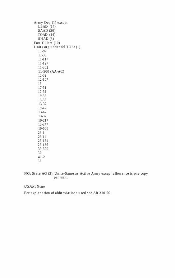

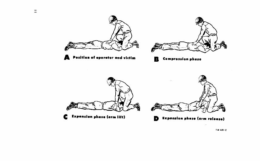
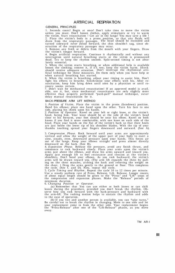
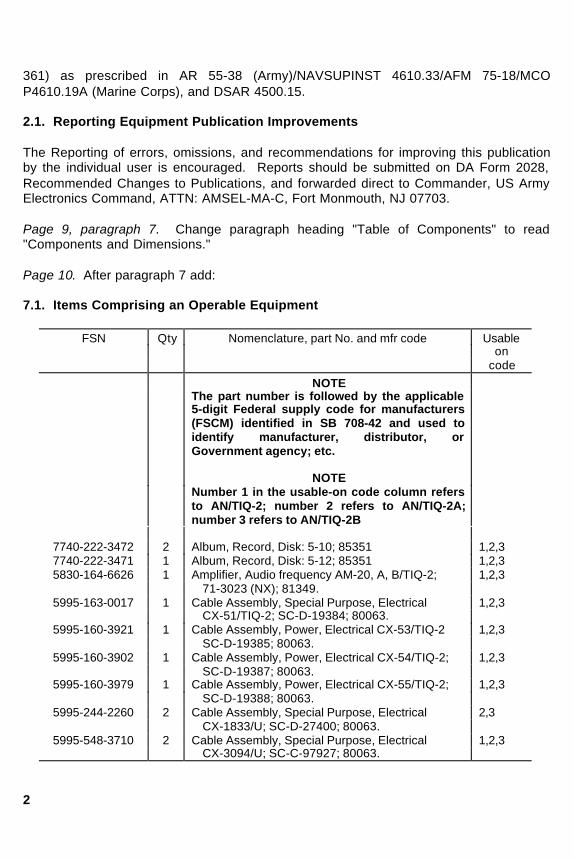
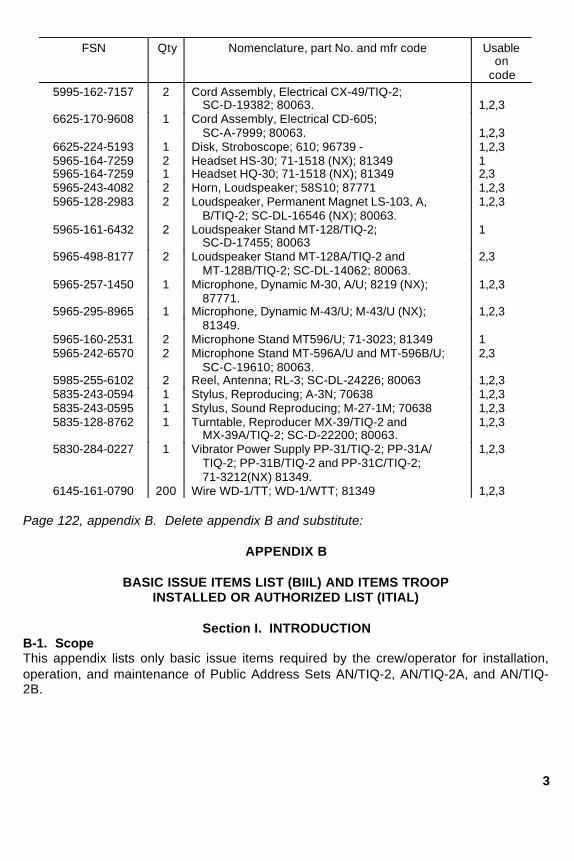
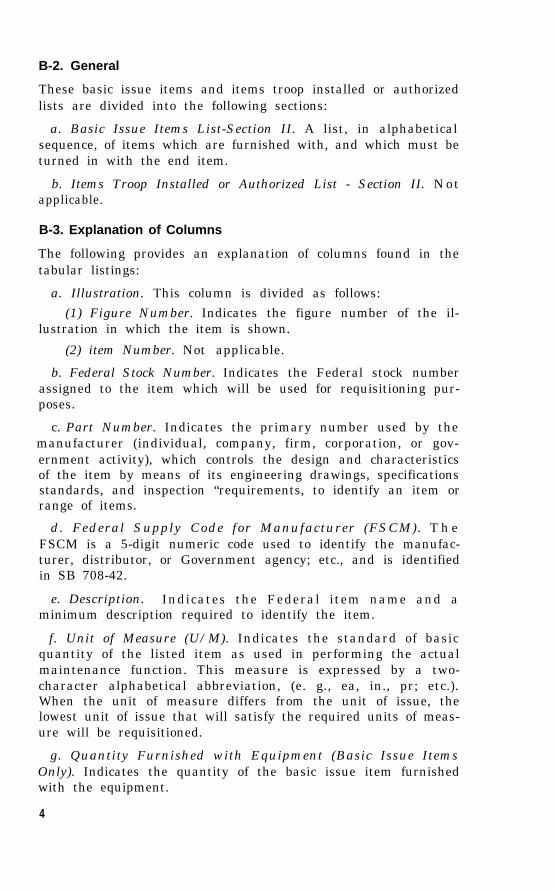
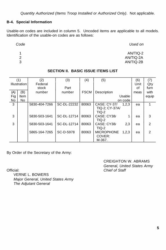
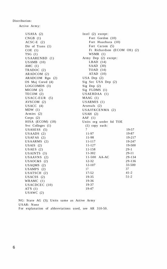

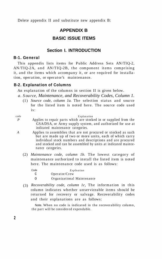

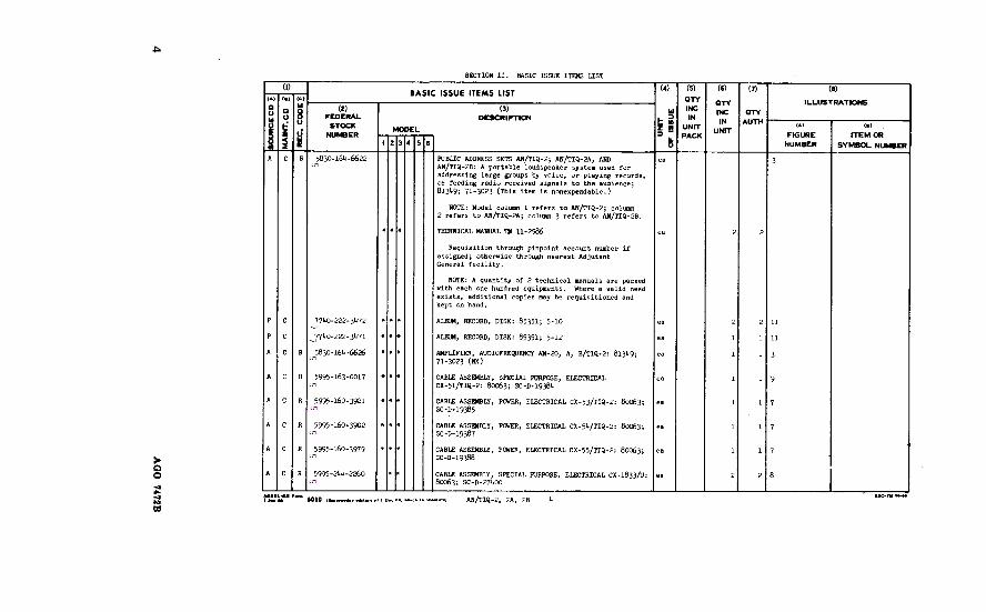

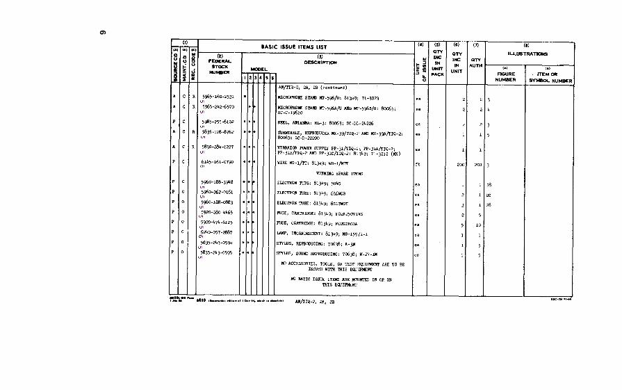

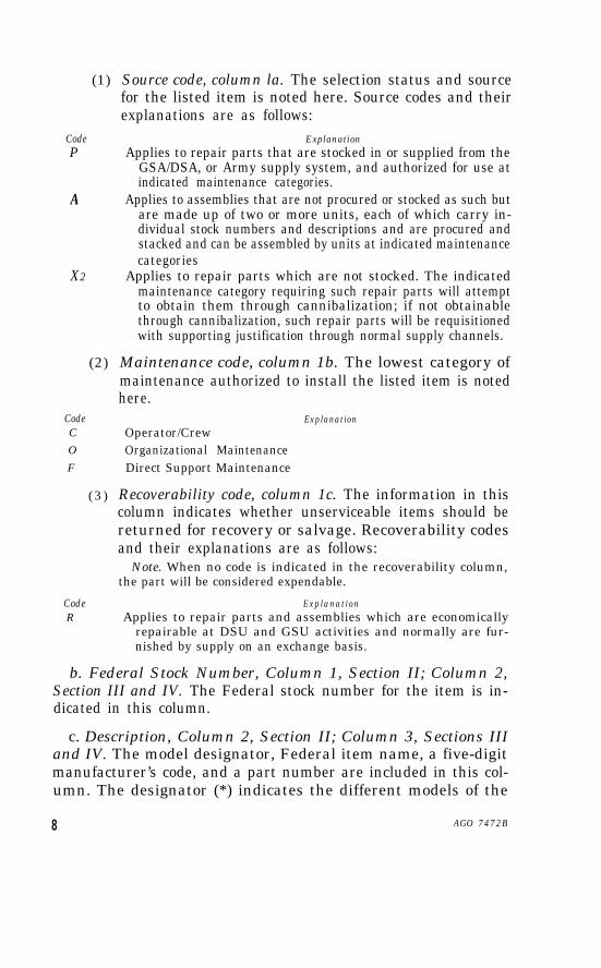


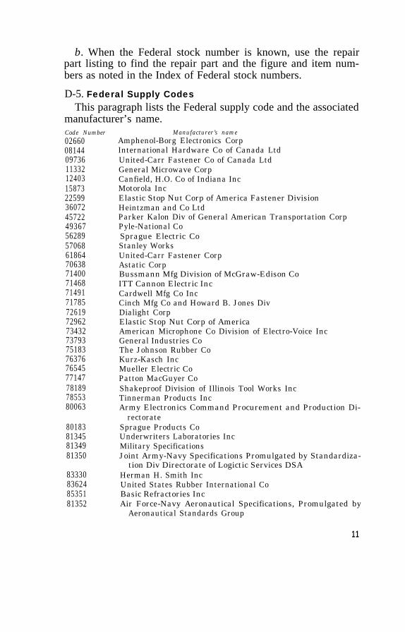

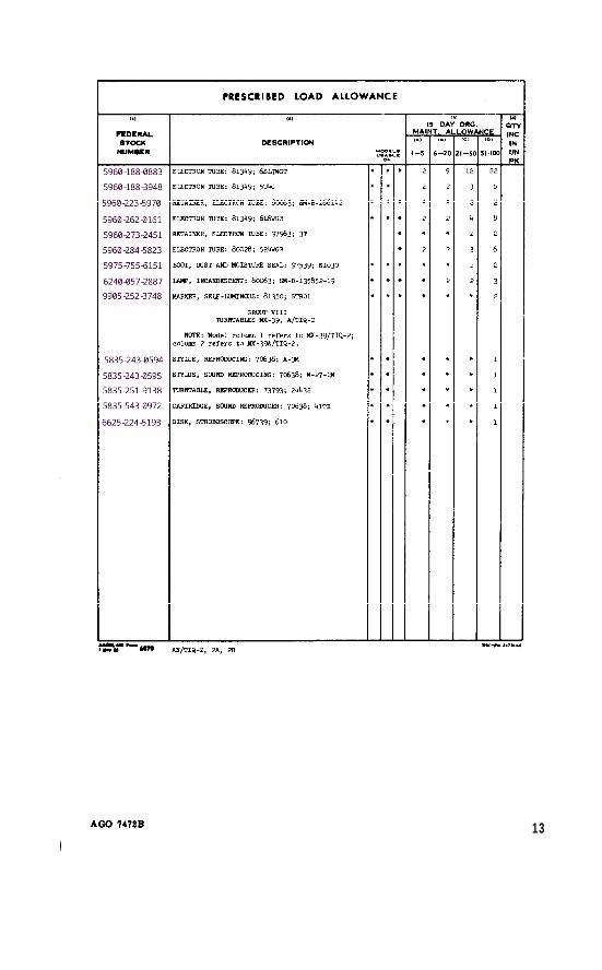


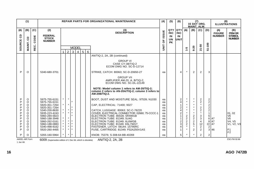
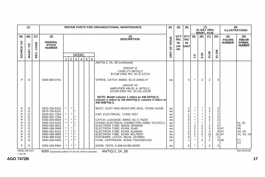


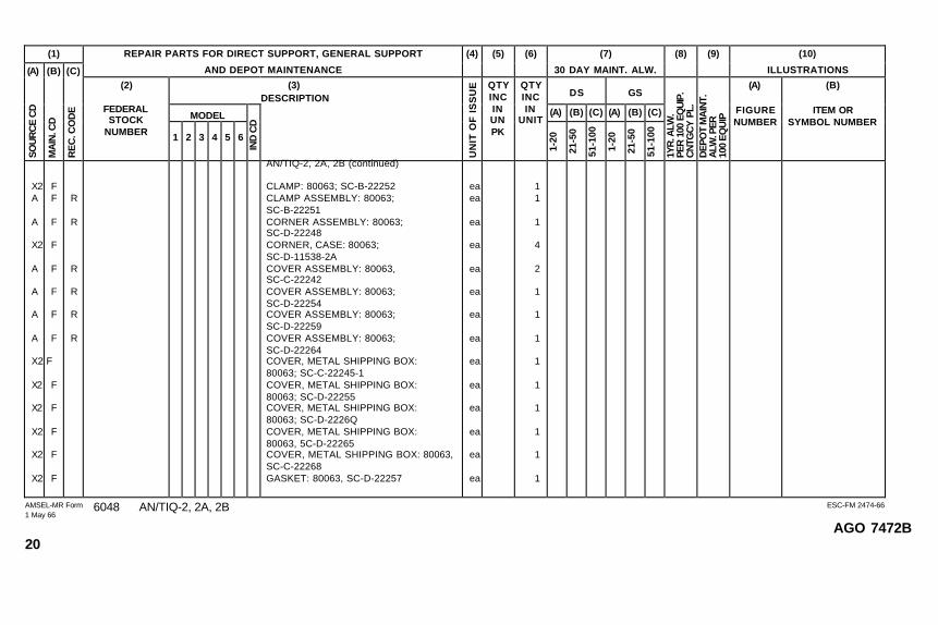
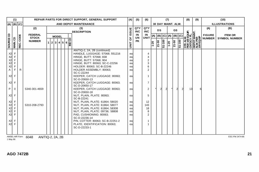
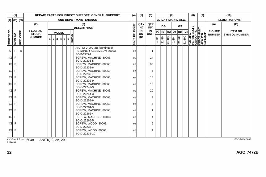
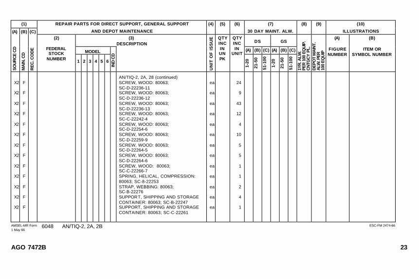
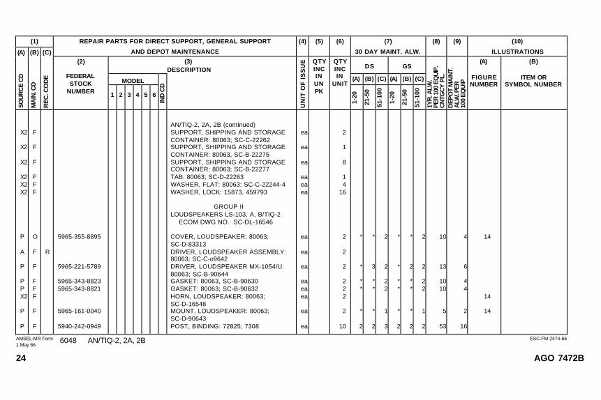
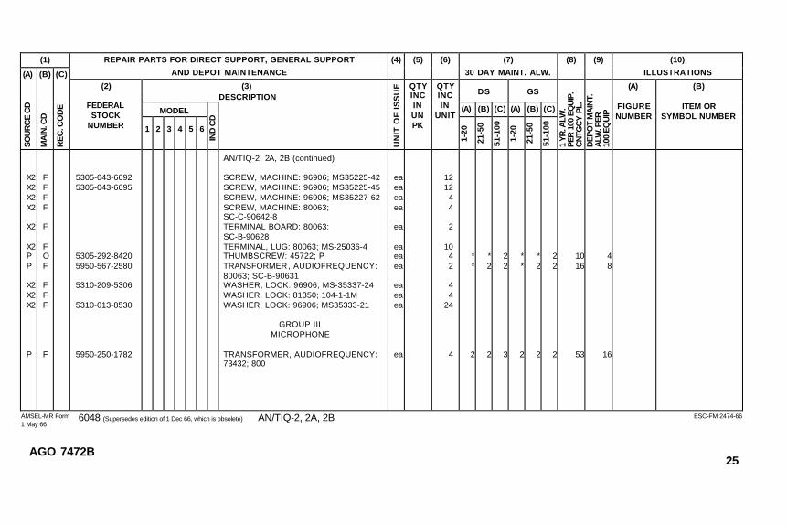
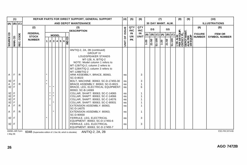


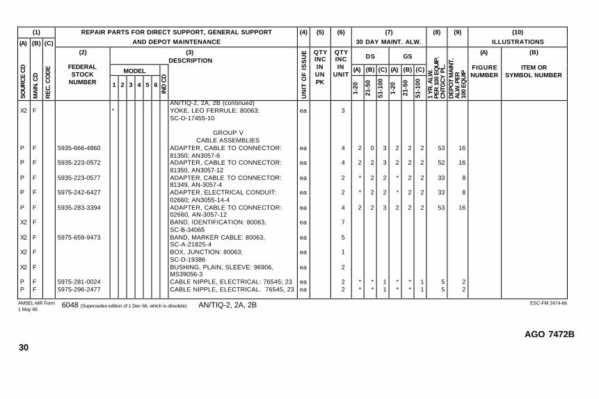


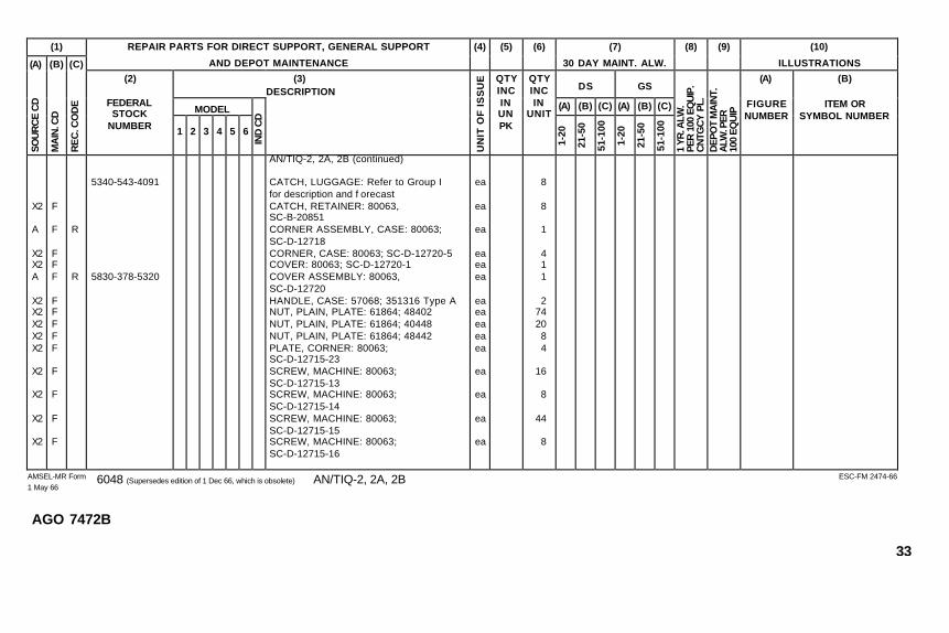
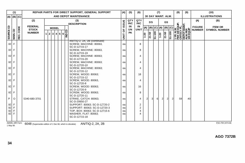
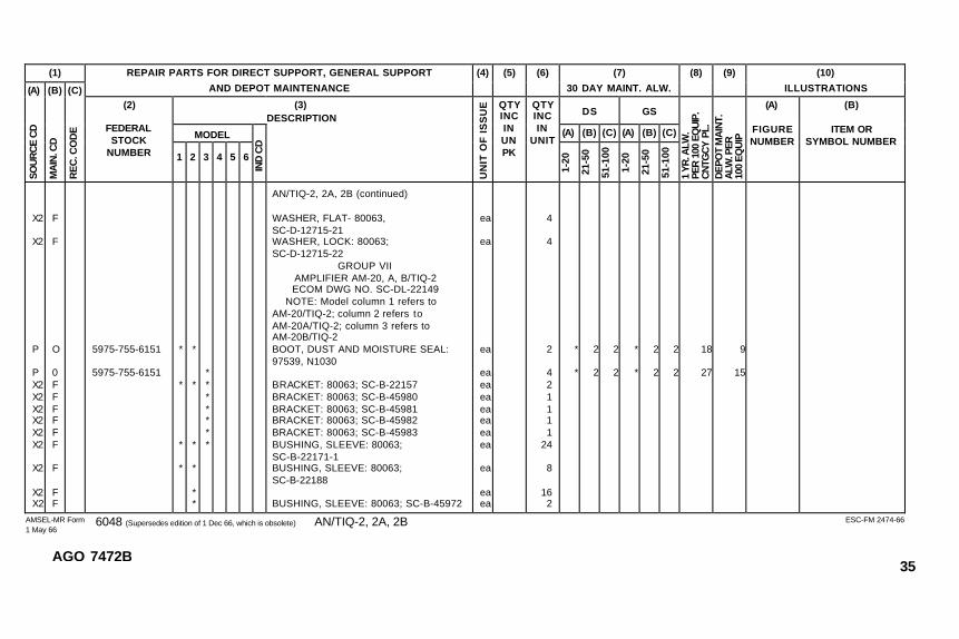
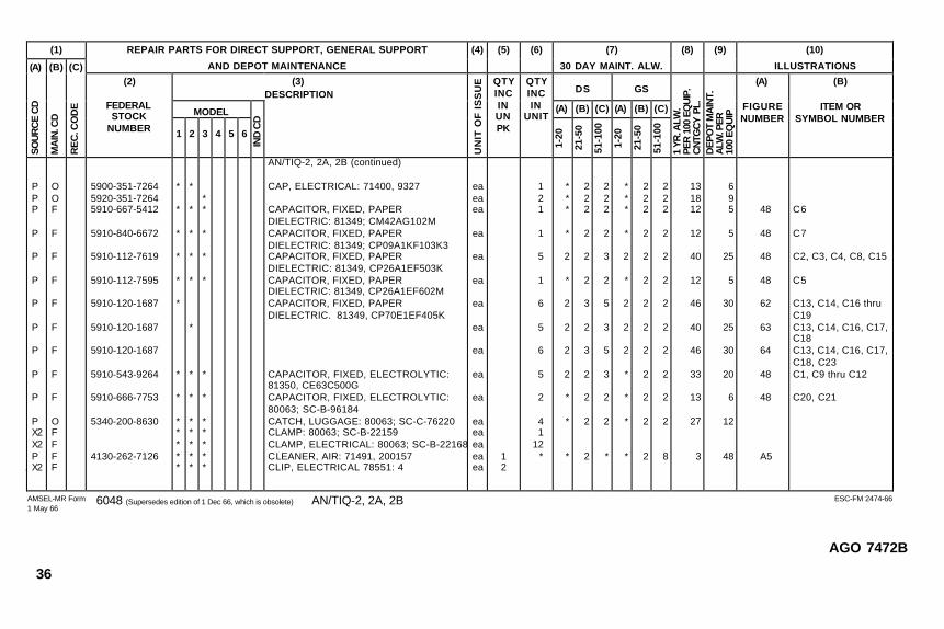
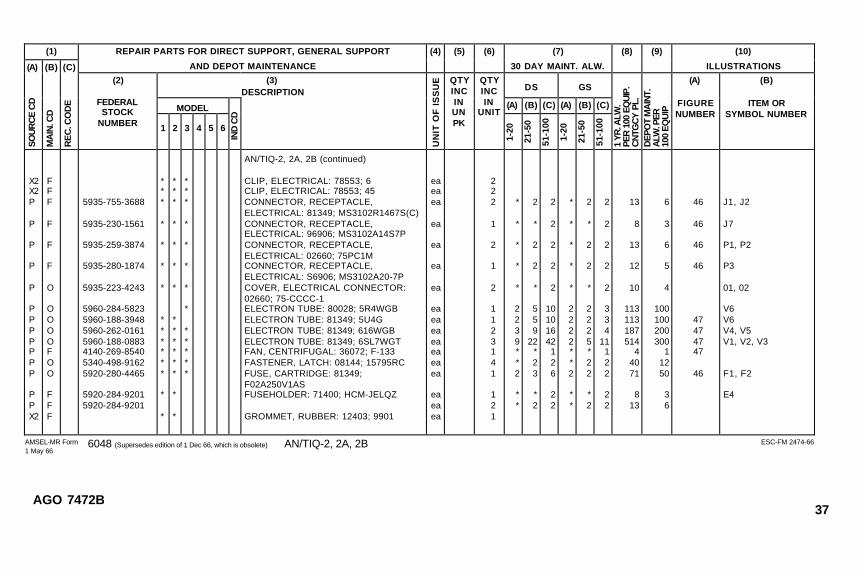

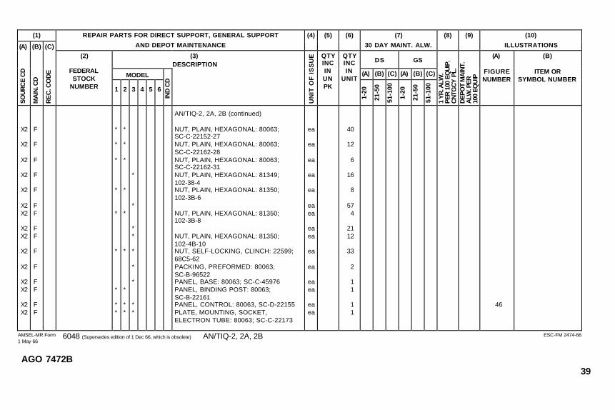
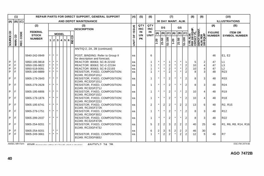

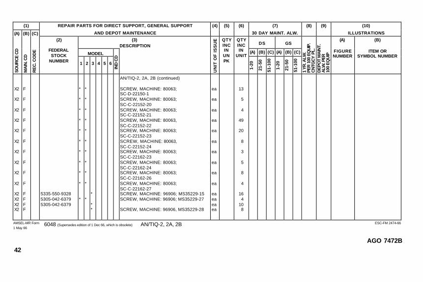

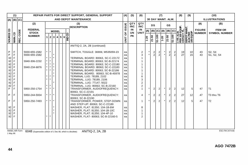

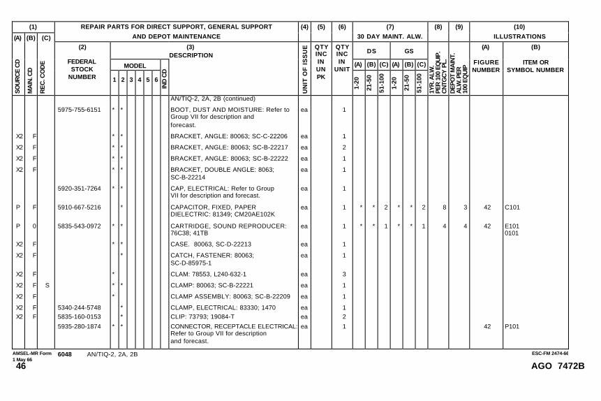

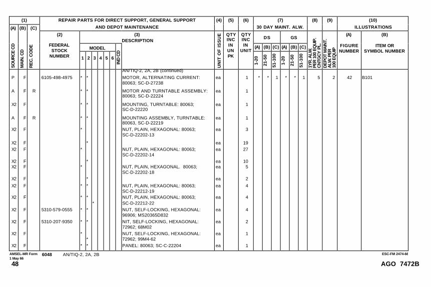
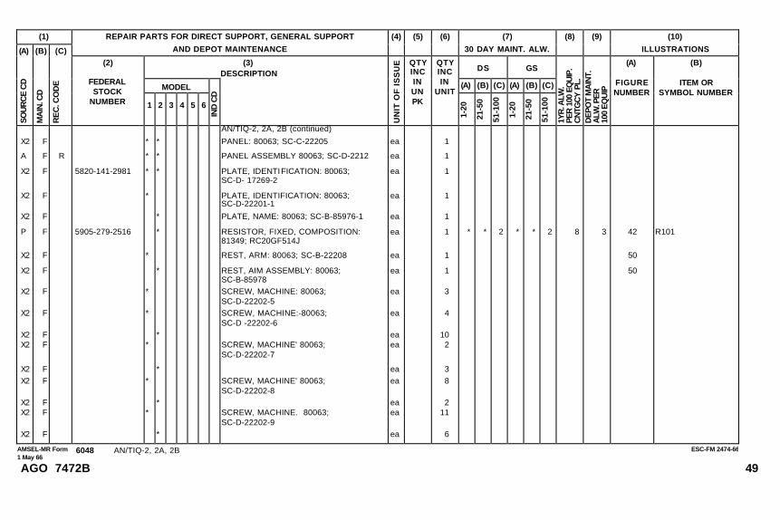

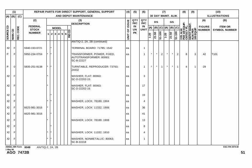


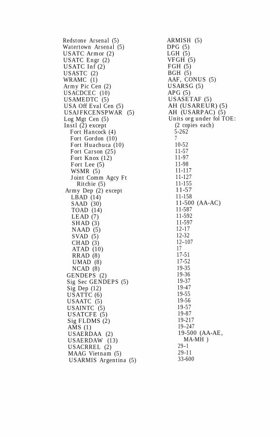

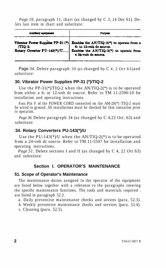
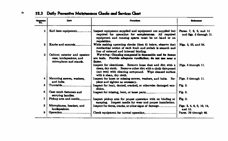
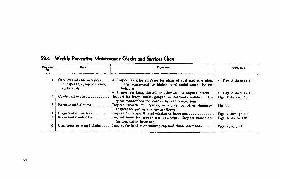


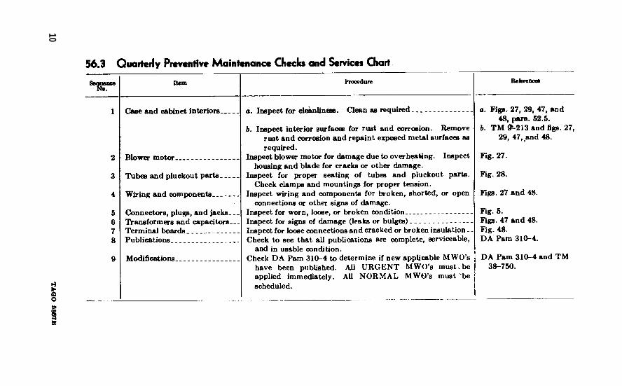
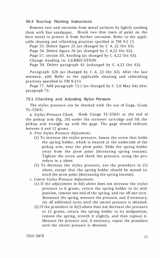


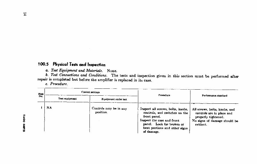


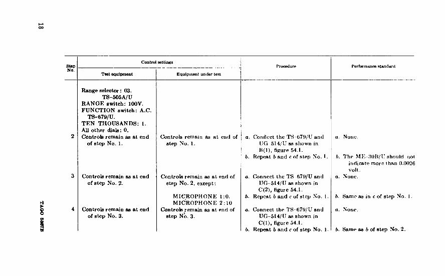


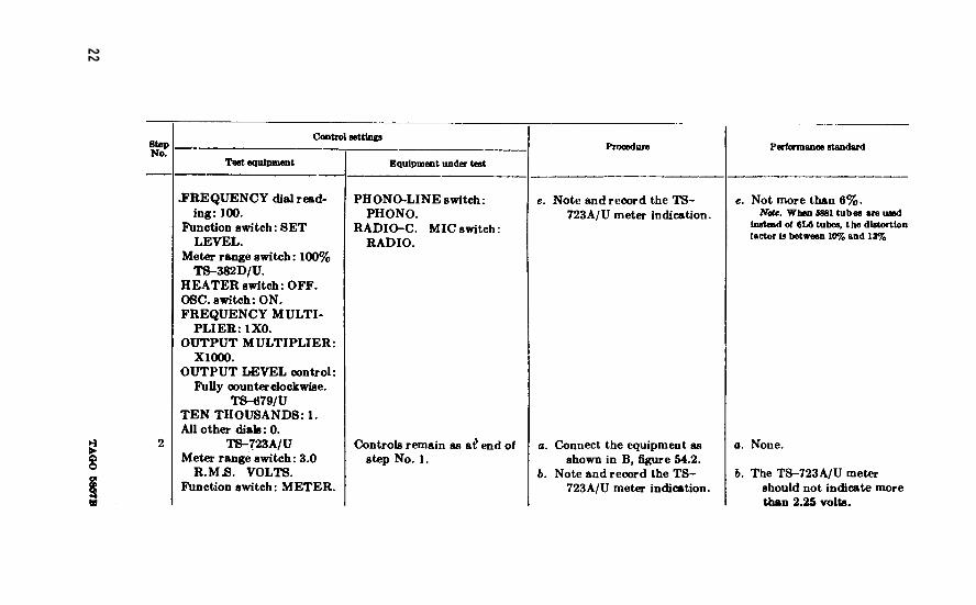

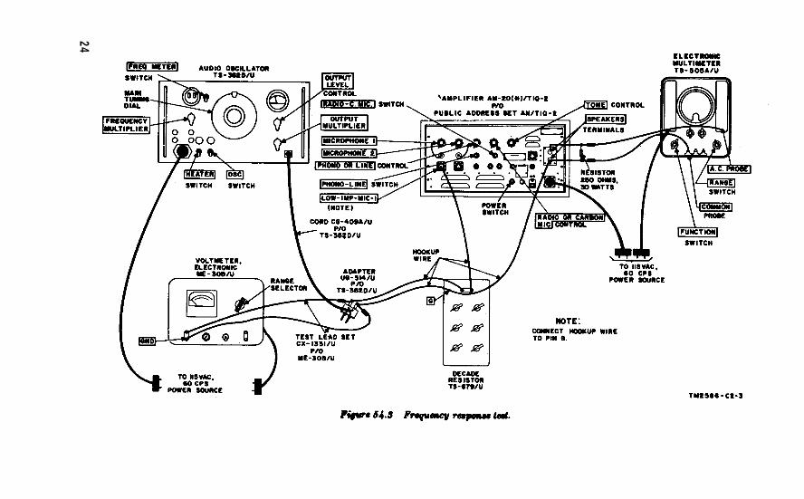
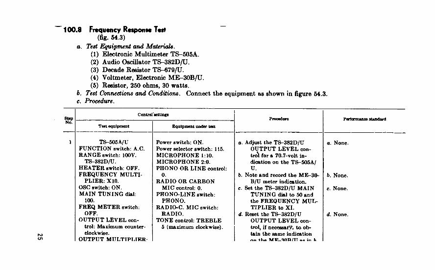

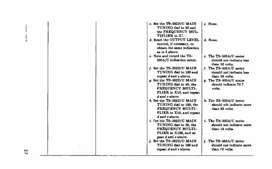
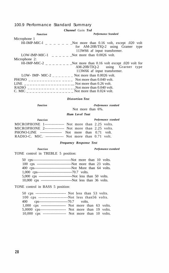
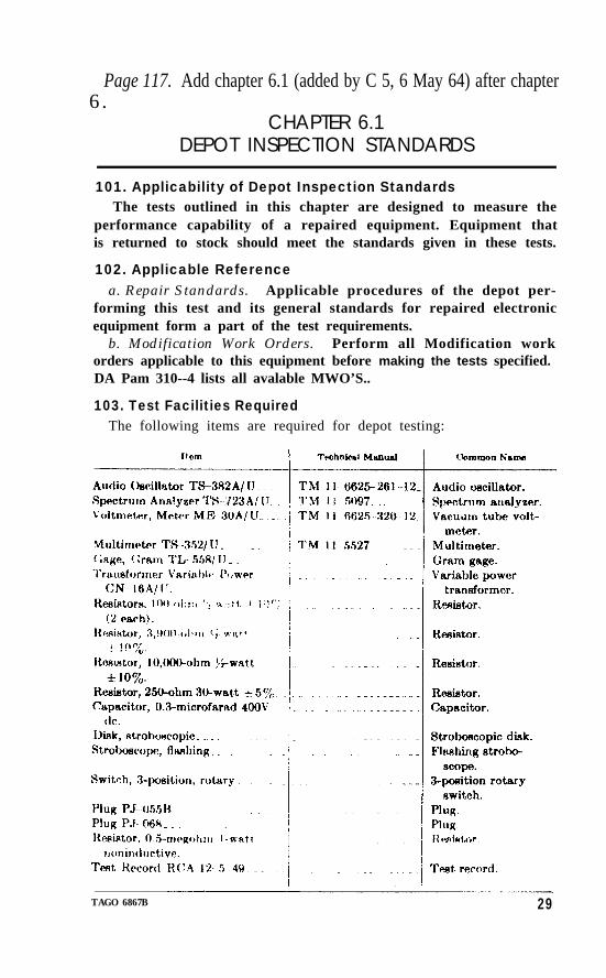


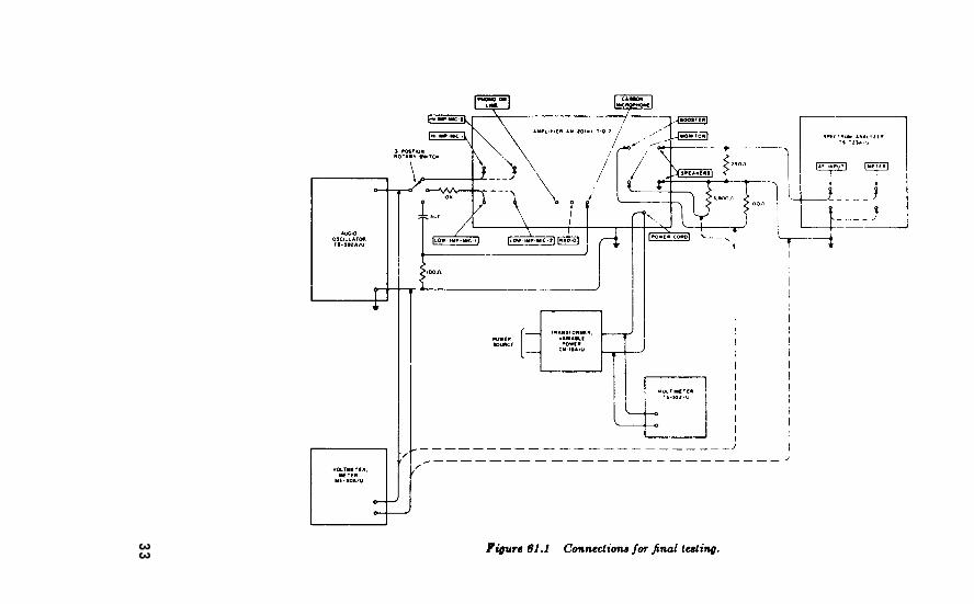

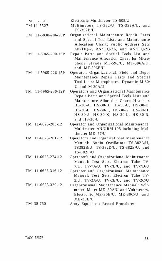

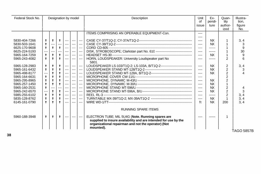
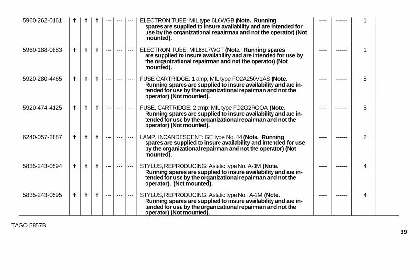
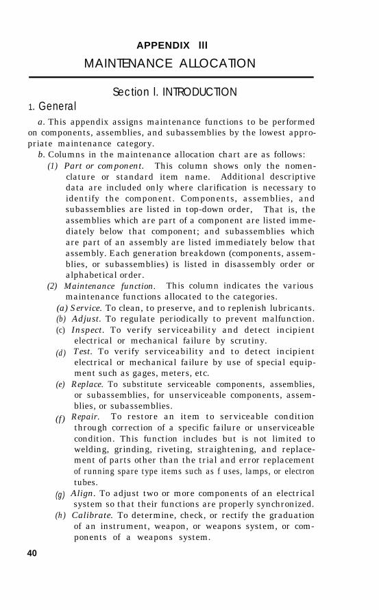
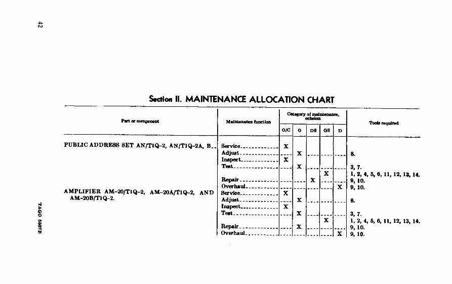
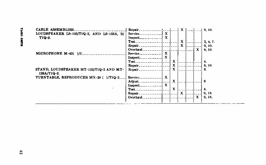


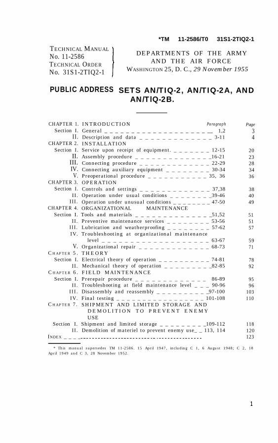
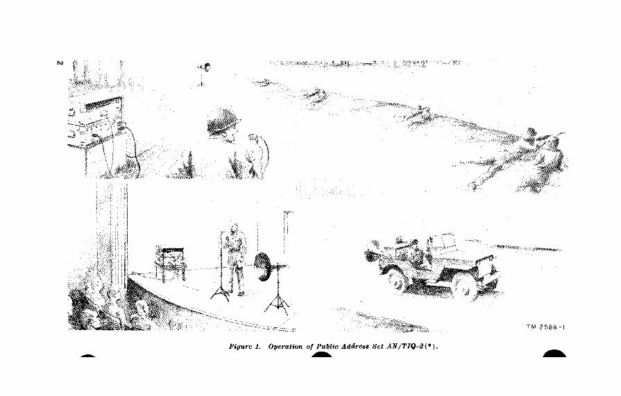
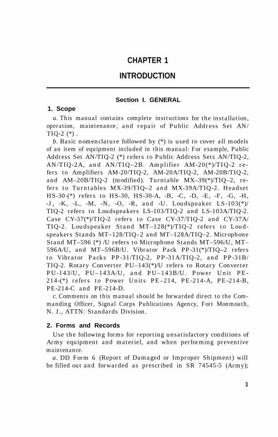
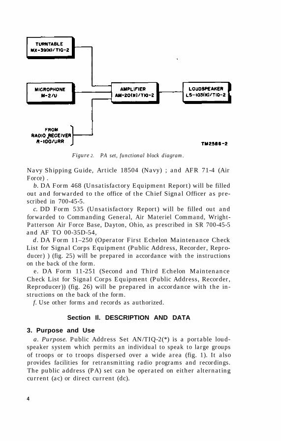


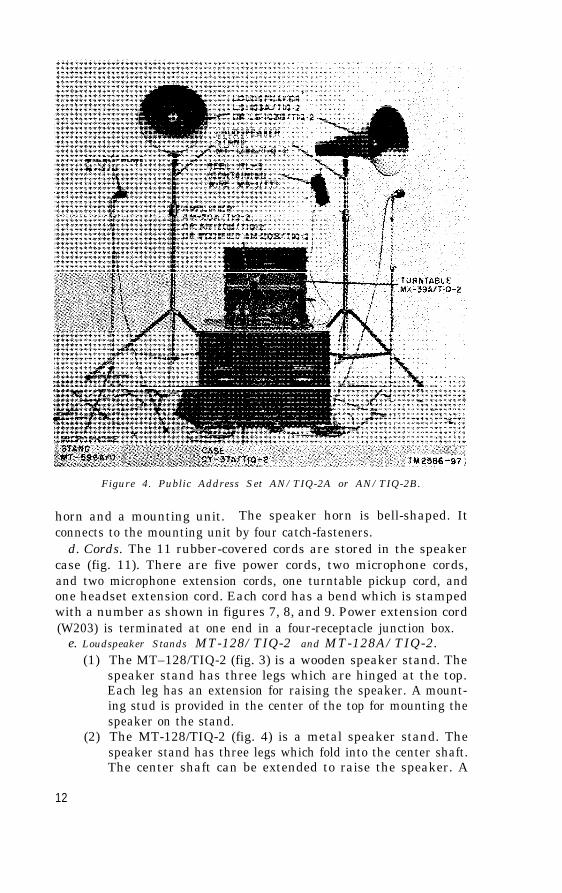
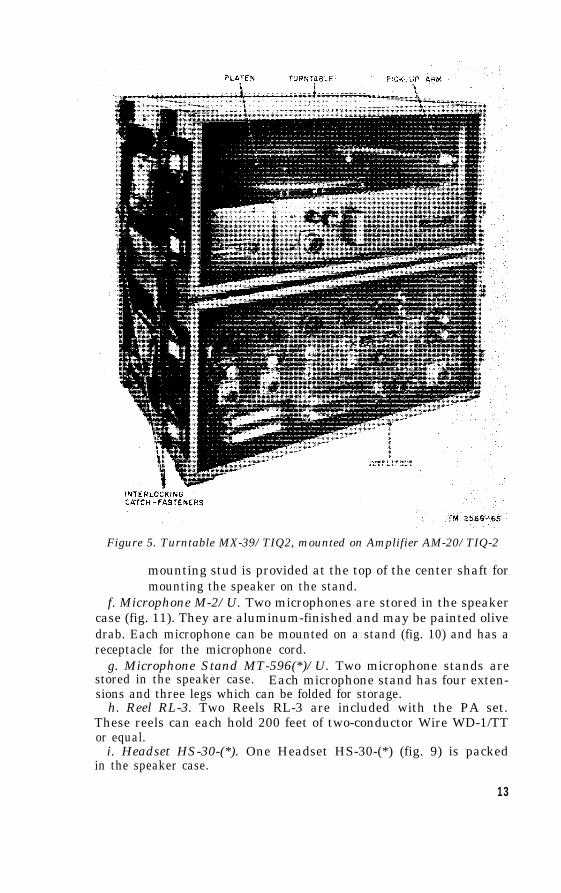
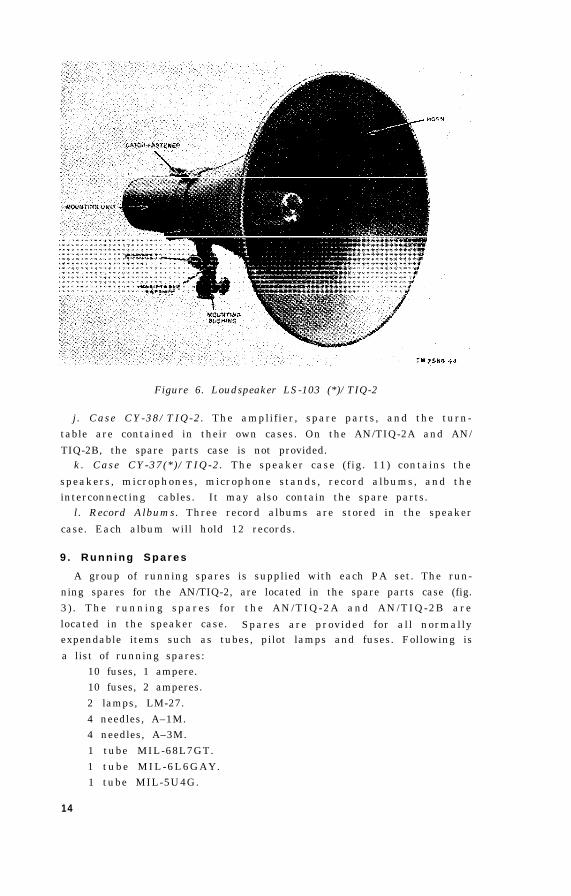


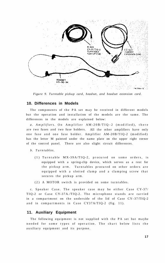
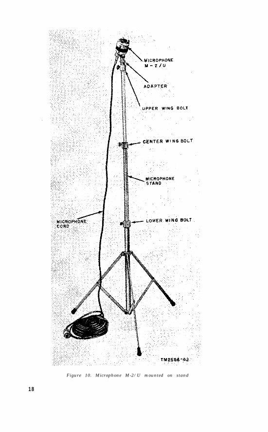
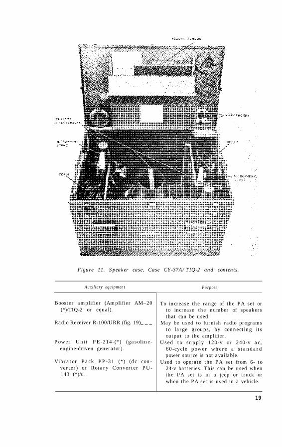
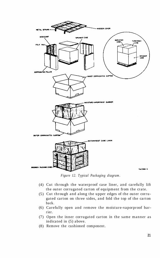
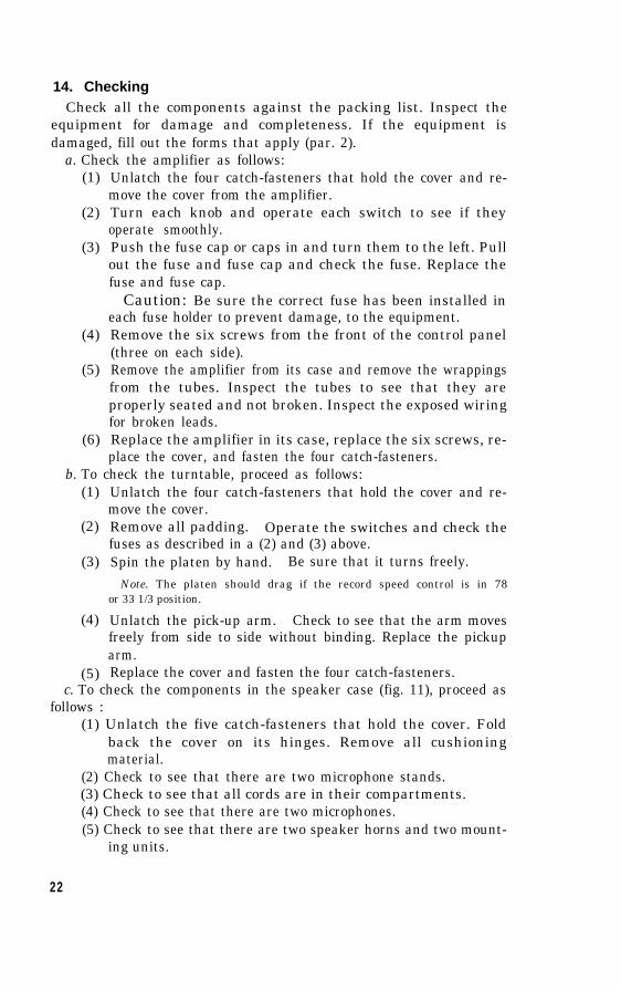

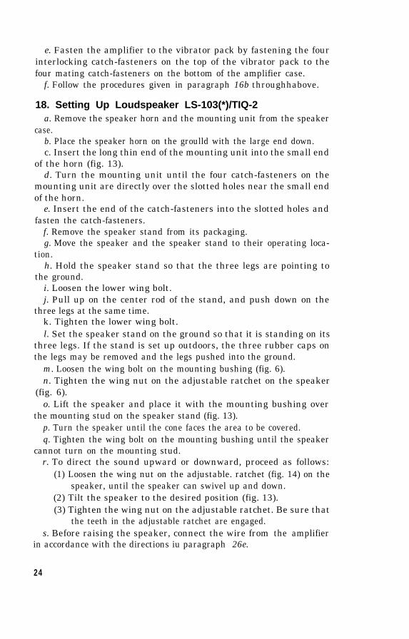

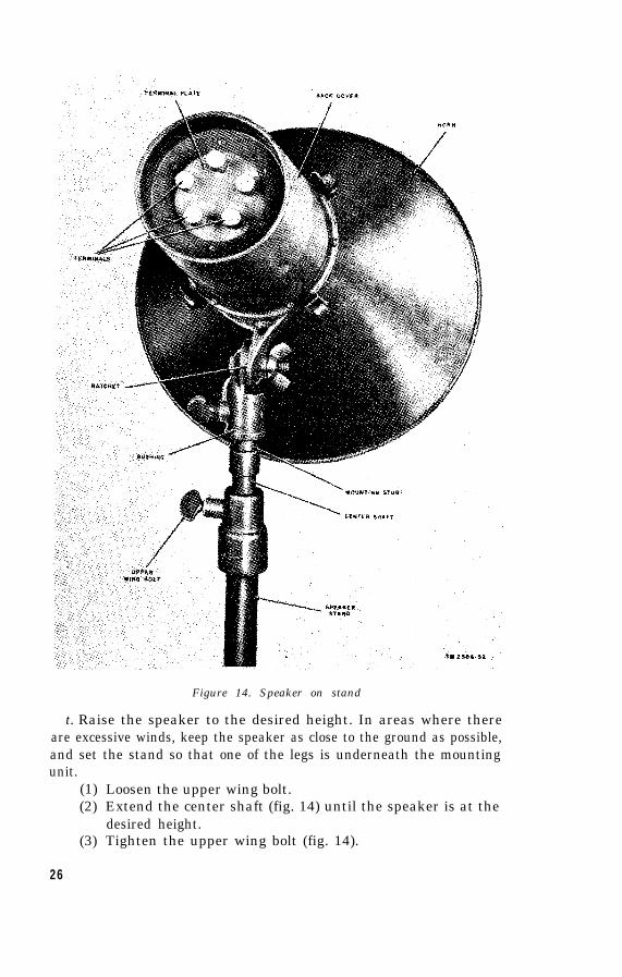


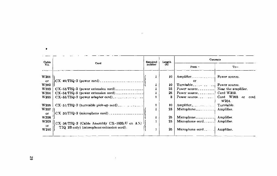


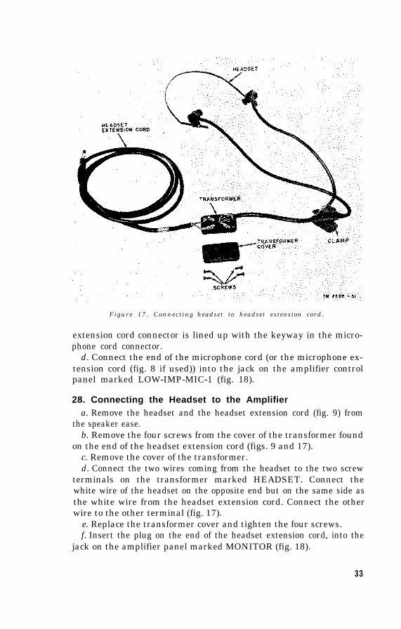


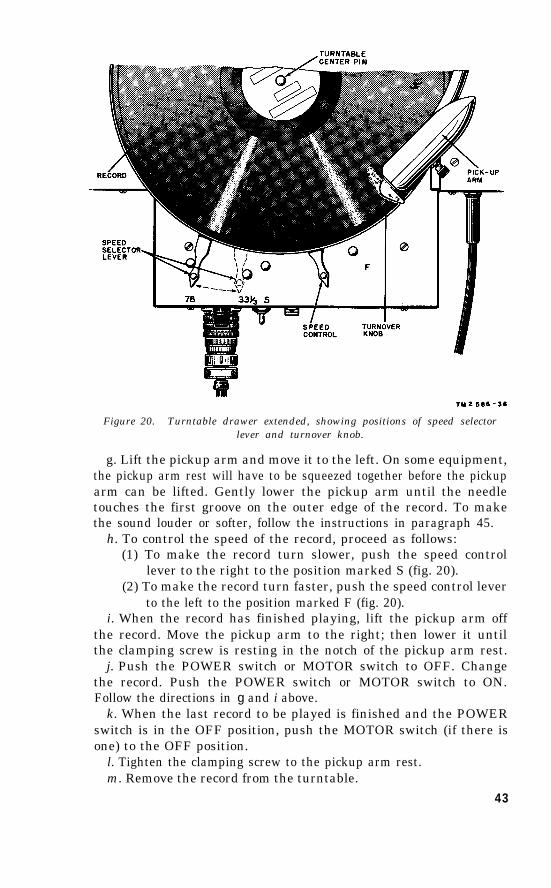
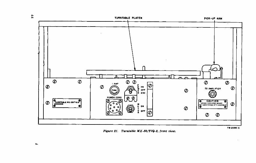


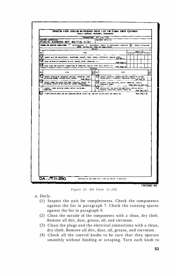

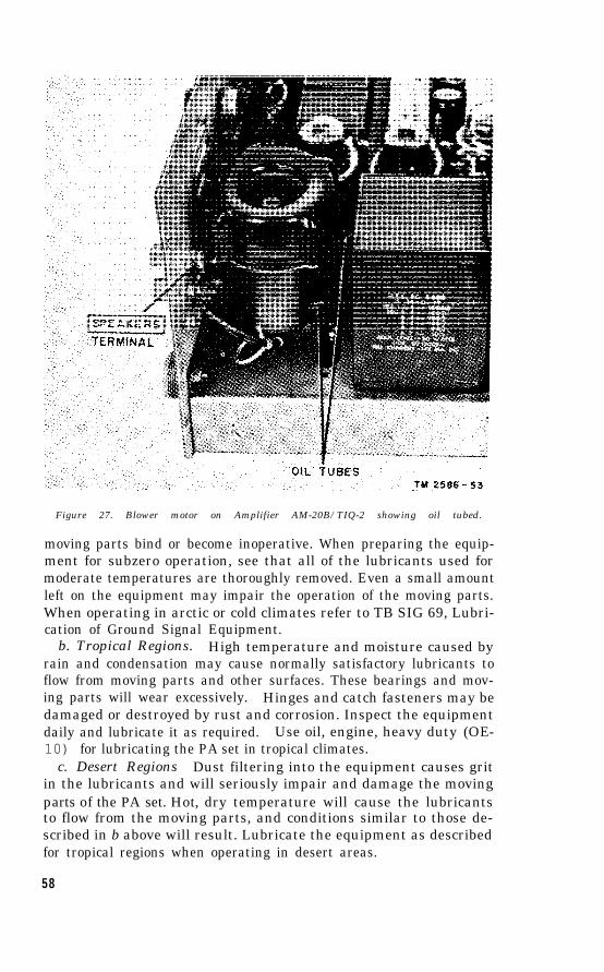


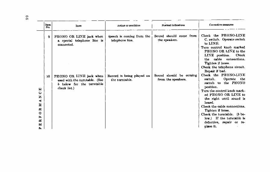
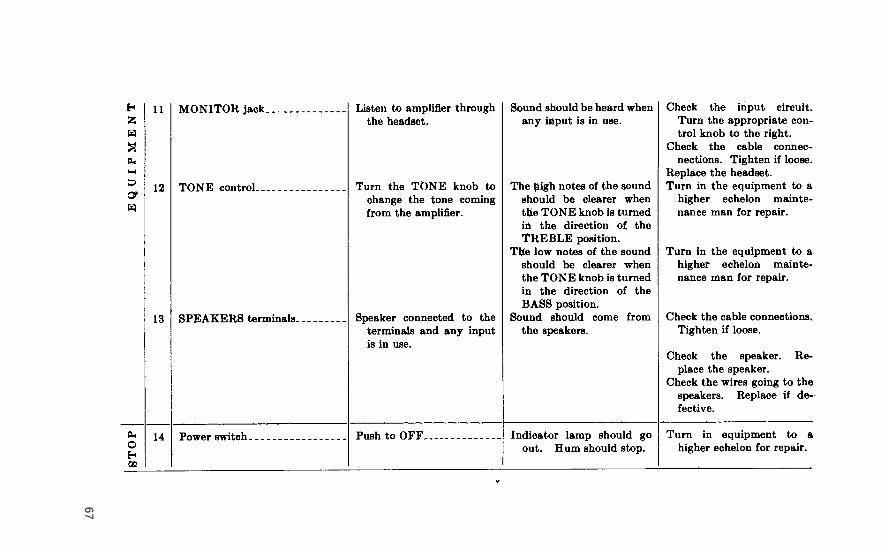
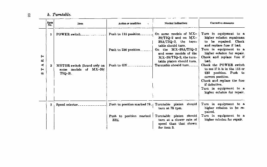
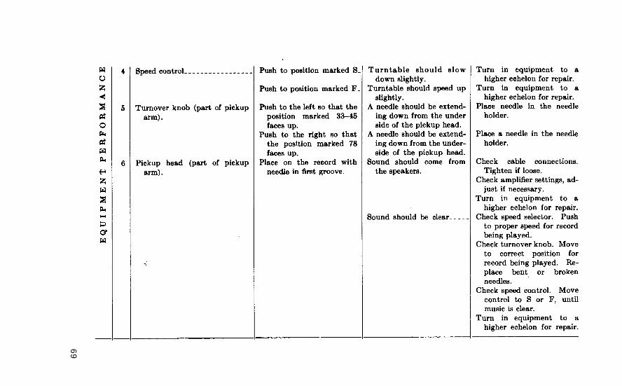
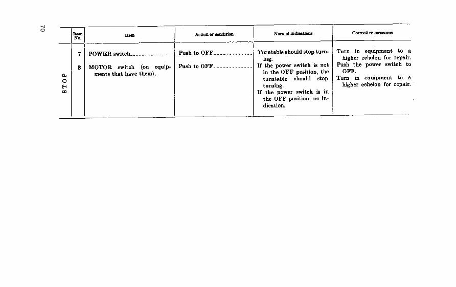


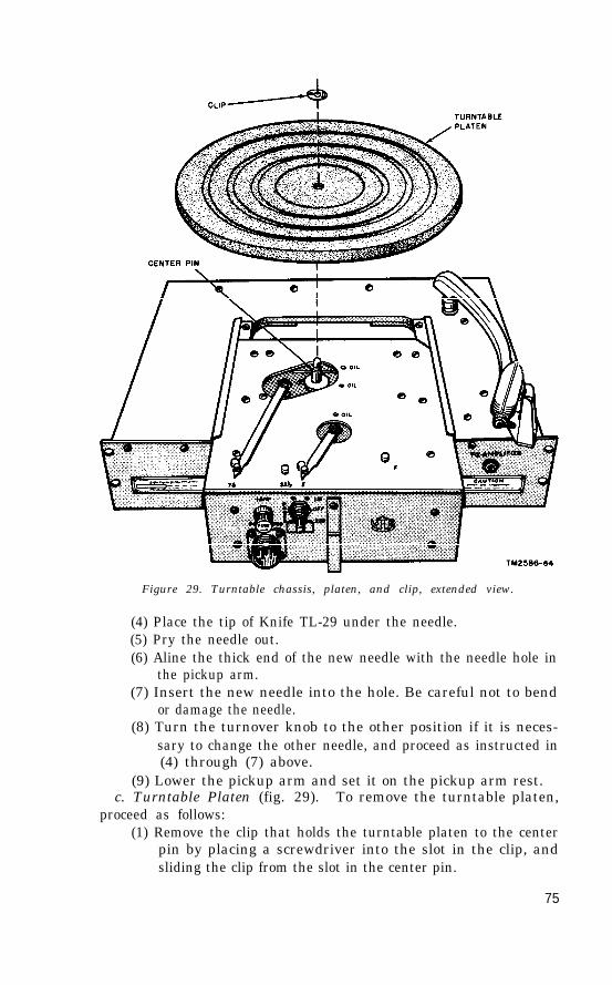


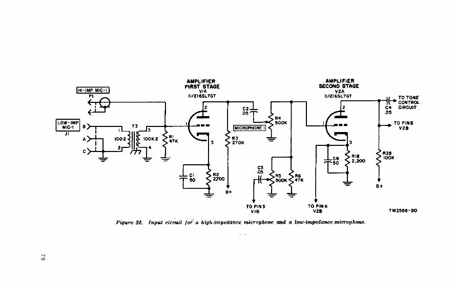
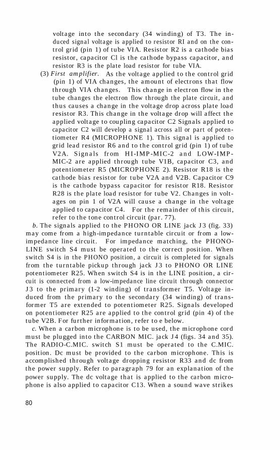

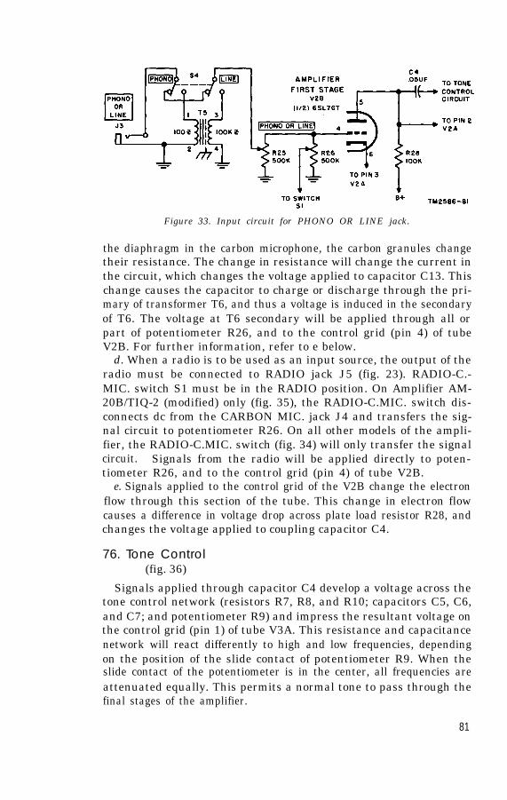
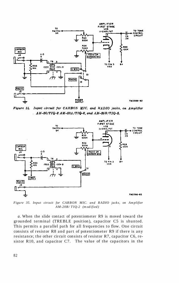


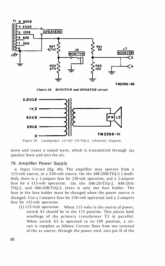
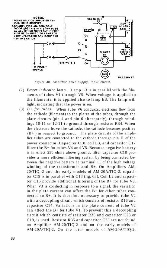


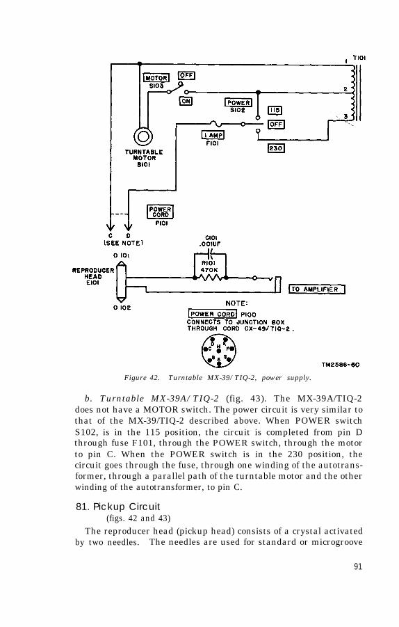

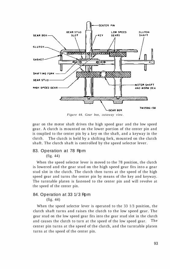

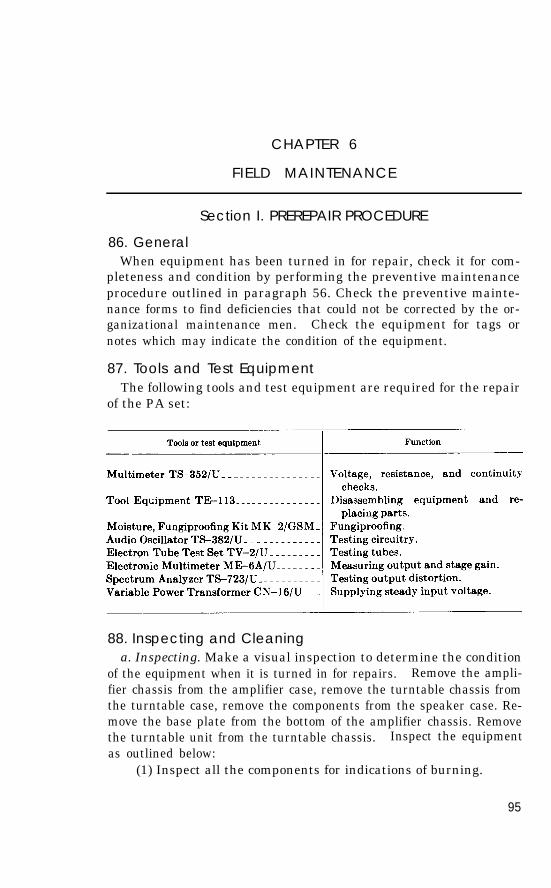

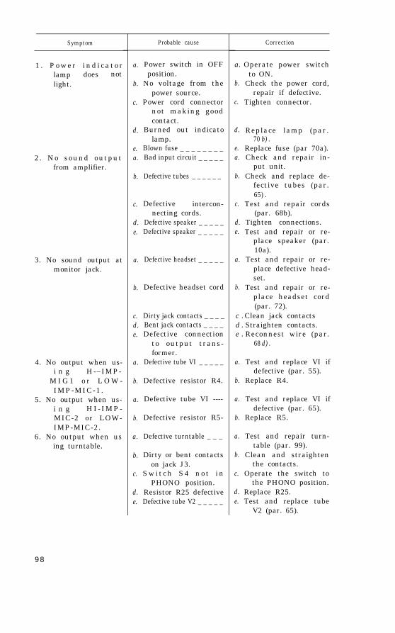


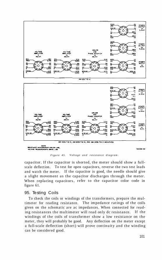
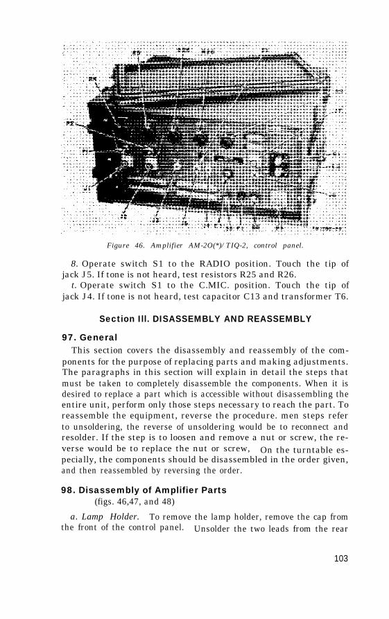
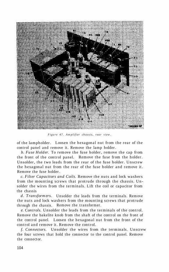
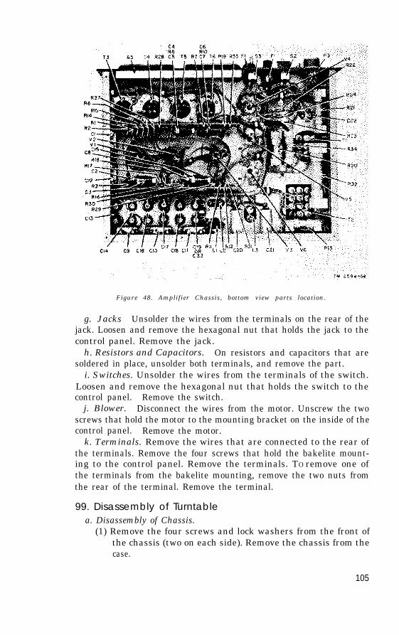
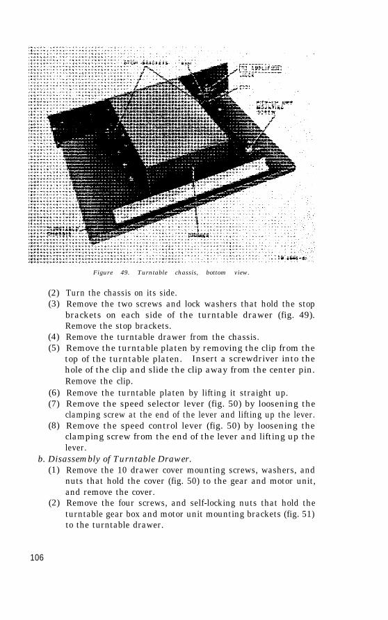
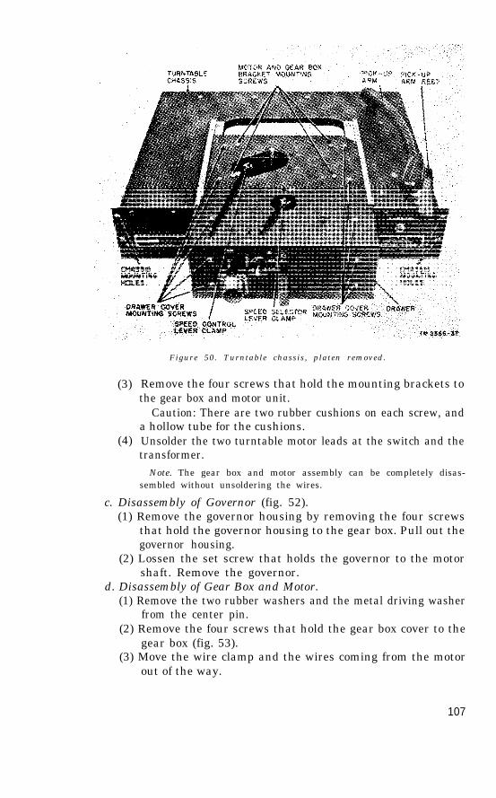
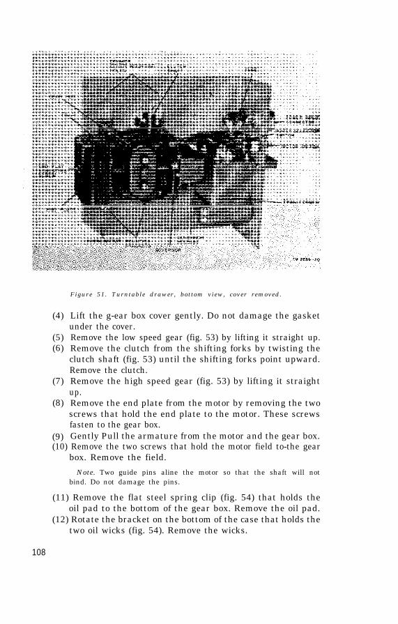

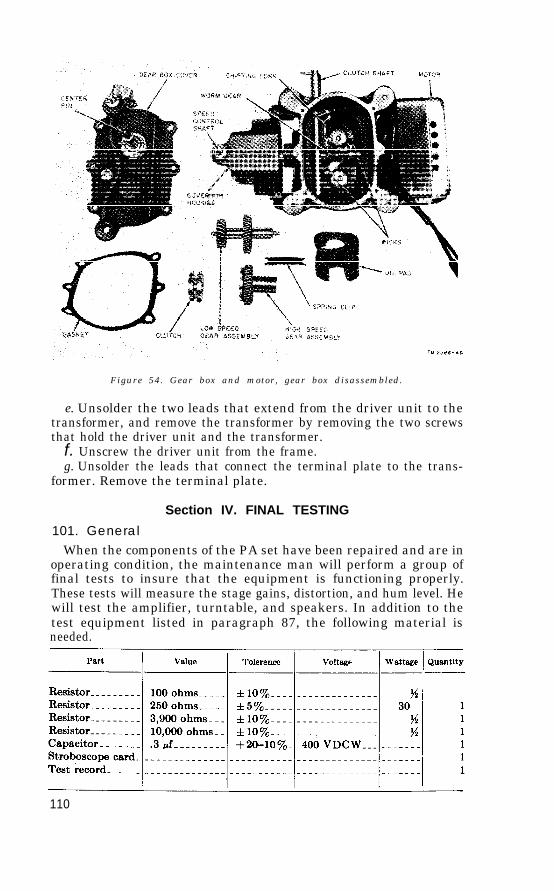


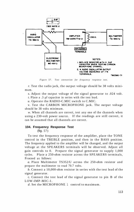
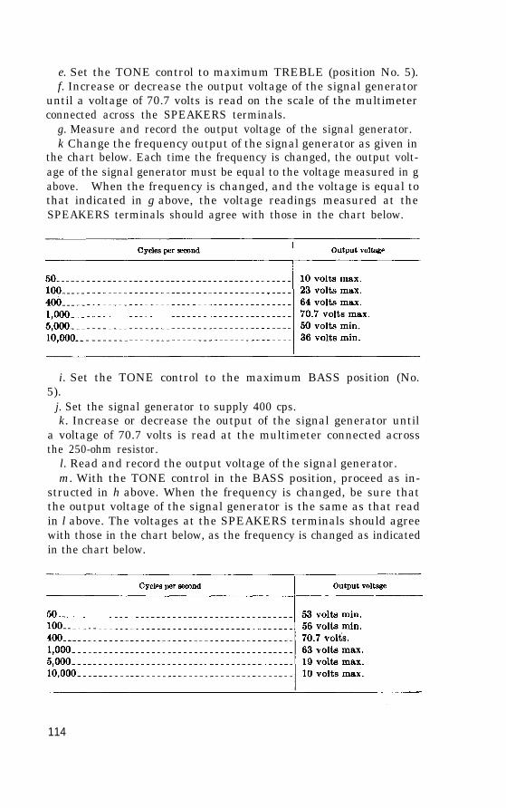
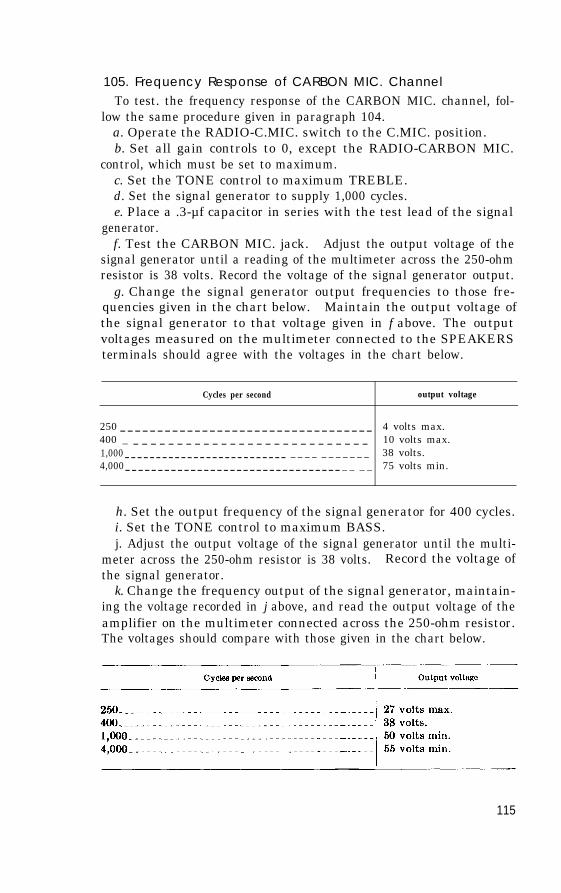

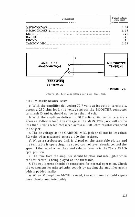

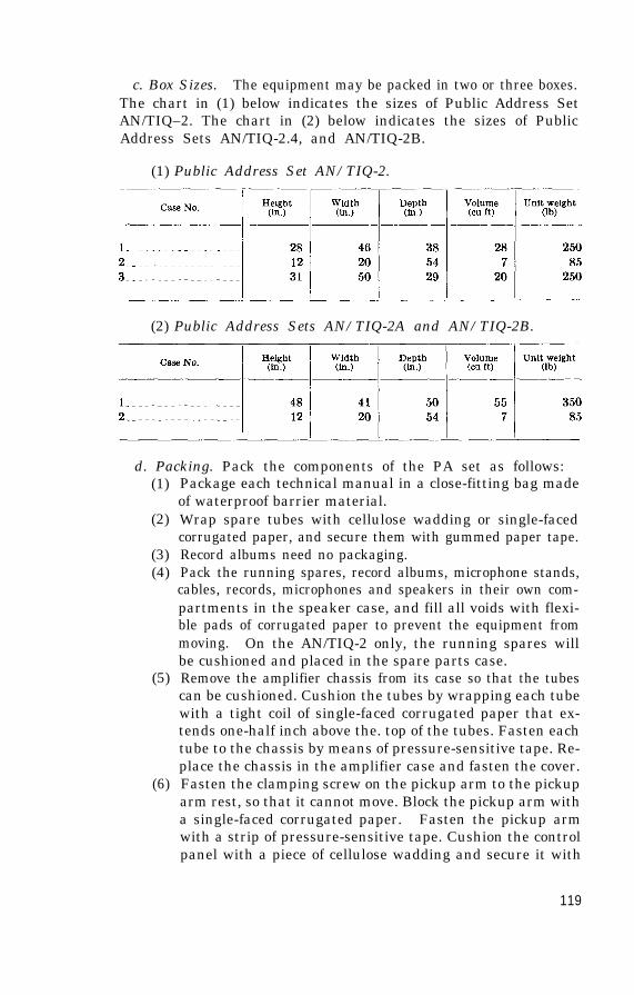
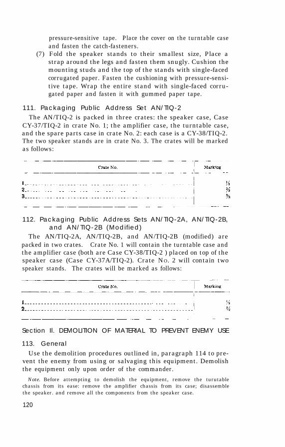
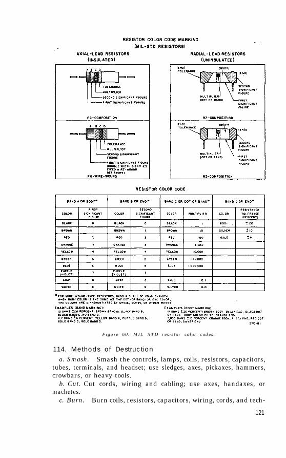

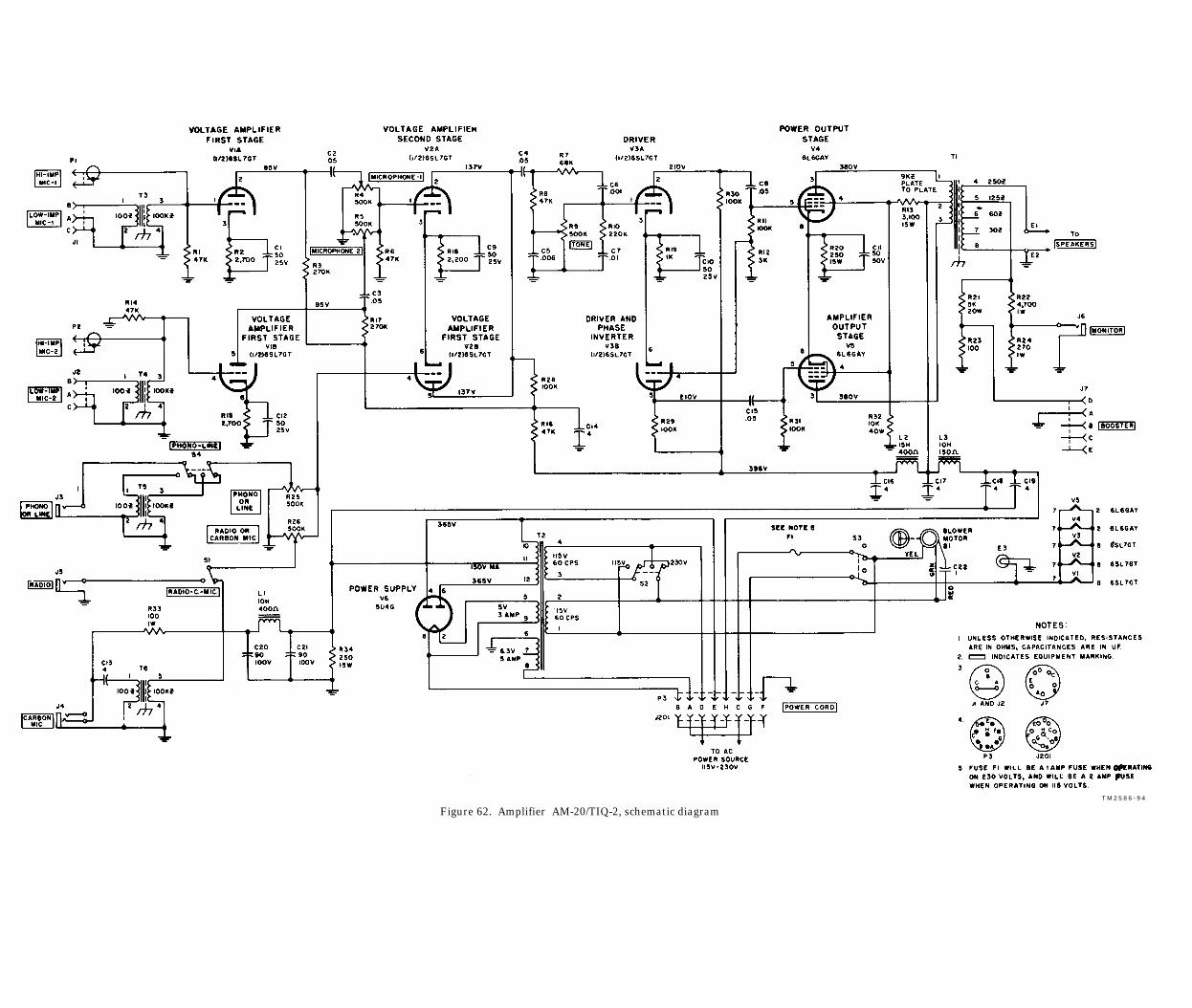

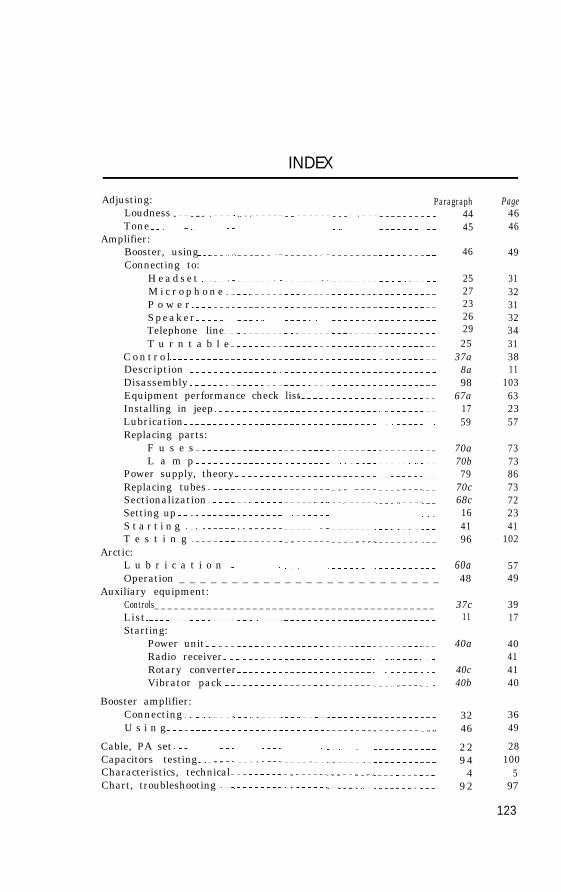

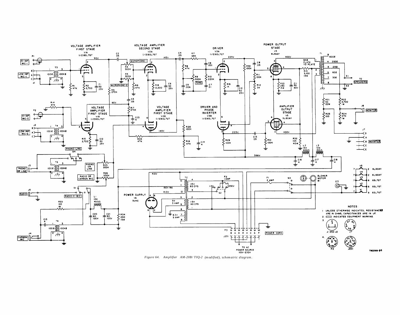


![M750 Usa Www.ducati-manuals.com 2002[1]](https://static.documents.pub/doc/80x56/55cf9956550346d0339cddac/m750-usa-wwwducati-manualscom-20021.jpg)


