TM 11-4920-209-15-1 DEPARTMENT OF THE ARMY TECHNICAL MANUAL OPERATOR, ORGANIZATIONAL, DS, GS, AND DEPOT MAINTENANCE MANUAL INCLUDING REPAIR PARTS AND SPECIAL TOOLS LIST TABLE, TILTING, GYRO INSTRUMENT TESTING MX-4042A/ASW-12 This copy is a reprint which includes current pages from Changes 1. HEADQUARTERS, DEPARTMENT OF THE ARMY MAY 1968
Transcript
TM 11-4920-209-15-1DEPARTMENT OF THE ARMY TECHNICAL MANUAL
OPERATOR, ORGANIZATIONAL, DS, GS,
AND DEPOT MAINTENANCE MANUAL INCLUDING
REPAIR PARTS AND SPECIAL TOOLS LIST
TABLE, TILTING, GYRO INSTRUMENT
TESTING MX-4042A/ASW-12
This copy is a repr int which includes current
p a g e s f r o m C h a n g e s 1 .
H E A D Q U A R T E R S , D E P A R T M E N T O F T H E A R M Y
MAY 1968
i
TM 11-4920-209-15-1
TECHNICAL M A N U A L HEADQUARTERSDEPARTMENT OF THE ARMY
No. 11-4920-209-15-1 W ASHINGTON, DC, 10 May 1968
Operator, Organizational, DS, GS, and Depot MaintenanceManual Including Repair Parts and Special Tool Lists
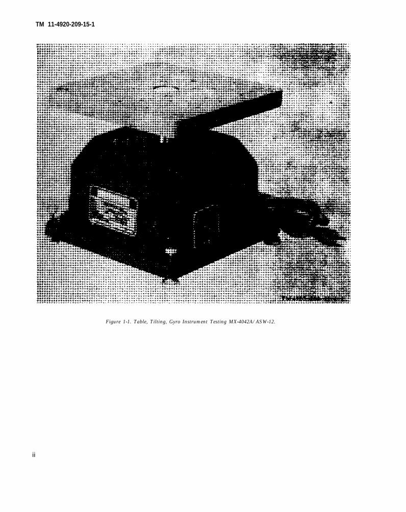
1-1. ScopeThis manual describes Table, Tilting, Gyro In-strument Testing MX-4042A/ASW-12 (fig. 1-1) andcovers its operation and maintenance. It includesinspection and lubrication of the equipment,troubleshooting, and maintenance service andinspection procedures.
1-2. Indexes of Publicationsa. DA Pam 310-4. Refer to the latest issue of DA
Pam 310-4 to determine whether there are neweditions, changes, or additional publications per-taining to the equipment.
b. DA Pam 310-7. Refer to DA Pam 310-7 todetermine whether there are modification workorders (MWO’S) pertaining to the equipment.
1-3. Forms and Recordsa. Reports of Maintenance and Unsatisfactory
Equipment. Maintenance forms, records, andreports which are to be used by maintenancepersonnel at all maintenance levels are listed inand prescribed by TM 38-750 (Army). Air Forcepersonnel will use AFM 66-1 for maintenancereporting and TO-00-35D54 for unsatisfactoryequipment reporting.
b. Report of Packaging and Handling Deficien-cies. Fill out and forward DD Form 6 (PackagingImprovement Report) as prescribed in AR 700-58/AFR 71-13, and DSAR 4145.8.
c. Discrepancy in Shipment Report (DISREP)(SF 361). Fill out and forward Discrepancy inShipment Report (DISREP) (SF 361) as pre-scribed in AR 55-38/AFR 75-18, and DSAR 4500.15.
1-3.1 Reporting of ErrorsThe reporting of errors, omissions, and recom-mendations for improving this publication by the
dividual user is encouraged. Reports should besubmitted on DA Form 2028 (RecommendedChanges to Publications and Blank Forms) and
forwarded direct to Commander, US Army Elec-tronics Command, ATTN: AMSEL-MA-Q, FortMonmouth, NJ 07703.
1-4. Purpose and UseThe Tilting Table MX-4042A/ASW-12 is an electri-cally driven table designed primarily for shop,production, and qualification testing of aircraftgyroscopic instruments. The motion of the tablesimulates a combination of roll, pitch, and yaw.The frequency of oscillation is six complete cyclesper minute. The head and mounting table may beadjusted to any angle up to fifteen degrees fromhorizontal.
1-6. Description of EquipmentThe Tilting Table MX-4042A/ASW-12 is electri-cally operated. Automatic reversing of direction ofrotation of the tilting head is provided. When setfor automatic reversing (OSC), it will reverse onceeach minute at the required cycle. When not set inthe automatic reversing position, it will operate ineither direction (left or right), at the discretion ofthe operator. The case for the instrument is ofruggedized construction. Adjustable levelingjacks are provided under the base for leveling themachine in conjunction with the table level on thetop of the unit.
1-7. Items Comprising an Operable Equip-mentTable, Tilting, Gyro Instrument Testing (part No.213250-3) (mfr code 30120) (NSN 4920-00-937-2554)comprises an operable equipment.
Change 1 1-1
TM 11-4920-209-15-1
CHAPTER 2INSTALLATION AND OPERATING INSTRUCTIONS
2-1. Unpackinga. Packaging Data. When packed for shipment,
the gyro testing table is placed in one shippingcarton. A typical shipping box and its contents areshown in figure 2-1. The dimensions and volume ofthe shipping carton are 12 ¾ x 12¾ ” x 12¾ ”.
b. Removing Contents.(1) Remove tape from top of cardboard box.(2) Remove dunnage from box.(3) Remove the two cardboard fillers and lift
instrument out of box.(4) Remove paper in which instrument is
wrapped and remove technical manual.
2-2. Checking Unpacked Equipmenta. Inspect the equipment for damage incurred
during shipment. If the equipment has beendamaged, report the damage on DD Form 6 (para
-1).. See that the equipment is complete as listed
~ the packing slip. If a packing slip is notavailable, check the equipment against the itemscomprising an operable equipment list (para 1-7).Report all discrepancies in accordance with TM38-750. Shortage of a minor assembly or part thatdoes not affect proper functioning of the equip-ment should not prevent use of the equipment.
c. If the equipment has been used or recon-ditioned, see whether it has been changed by amodification work order (MWO). If the equipmenthas been modified, the MWO number will appearon the front panel near the nomenclature plate. Ifmodified, see that any operational instructionchanges resulting from the modification havebeen entered in the equipment manual.
NOTECurrent MWO’S applicable to the equipment are listed in DA Pam 310-7.
2-3. Tools and Test Equipment Requiredfor InstallationNo tools or test equipment are needed forinstallation of the tilting table.
2-4. Controls and Indicators(fig. 2-2)
C,, !ttr,,/,, ri,(,lrc(tt8, r !’$(, (<t,<,,,
OFF-L-R-OSC switch . . . . . . . . . . In the OFF position, tllrns otYtable. In the LIiE”r posi-tion, table rotates left. Inthe RIGHT pwition, tablerotates right, In OX” posi-tion, table rotates one [ li -rection six times und thenreverses.
Table level (on tmp of Indicator for levelin~table). table.
(1) With the table top held firmly in itshorizontal position, adjust the leveling jackslocated on each corner of the base until the bubblein the table level is centered inside the inscribedcircle.
(2) Set the table in desired tilted position byloosening the locking screw located on the side ofthe head assembly and adjusting to desired angle.The maximum angle of tilt is 15 degrees (30degrees included angle) from horizontal, as indi-cated by the graduated scale. The stop screw maybe adjusted to limit the tilt of the head to anyangle between 0 and 15 degrees from horizontal.With the stop setscrew set to the desired tilt angle,it is not necessary to check the angle of the tableduring each operation. Push the table into itstilted position for making a test, and push it
Change 1 2-1
TM 11-4920-209-15-1
Figure 2-1. Packaging of Table, Tilting, Gyro InstrumentTesting MX-4O42A/ASW-12.
back to its horizontal position to take an instru- ting the OFF-L-R-OSC switch to the 0SCment reading. position. This automatically reverses the direc-
b. Starting. To start the table, set the OFF- tion of rotation every six cycles.
L-R-OSC switch to the desired position.2-7. Stopping Procedure
2-6. Automatic Reversing To stop the table, set the OFF-L-R-OSCAutomatic reversing is accomplished by set- switch to the OFF position.
2-4
T M 1 1 - 4 9 2 0 - 2 0 9 - 1 5 - 1
CHAPTER 3
MAINTENANCE
3-1. Scope of MaintenanceThe maintenance duties assigned to theorganizational repairman of Tilting TableMX-4042A/ASW-12 are listed below with areference to the paragraph covering the specificmaintenance function.
a. Daily preventive maintenance checks andservices (para 3-5).
b. Weekly preventive maintenance checksand services (para 3-6).
c. Monthly preventive maintenance checksand services (para 3-7).
d. Cleaning (3-8).
e. Cleaning and touchup maintenance in-structions (para 3-9).
f. Lubrication (para 3-10).
g. Troubleshooting (para 3-11).
3-2. Special Tools and Equipment Requiredfor Maintenance
a. Tool Equipment. Tool Kit, ElectronicEquipment TK–100/G or Tool Kit, ElectronicEquipment TK-105/G, and Multimeter TS-352B/U are required for maintenance.
b. Materials.(1) Cleaning compound (Federal stock
No. 7930-395-9542).
Warning: Prolonged breathing of clean-ing compound is dangerous; make certain thatadequate ventilation is provided. Cleaningcompound is flammable; do not use near aflame.
(2) Cleaning cloth.(3) Grease, aircraft and instrument
(GL) (Federal stock No. 9150-257-5449).(4) Fine sandpaper.(5) Touchup paint.
3-3. Preventive MaintenancePreventive maintenance is the systematic care,servicing, and inspection of equipment to pre-vent the occurrence of trouble, to reduce down-time, and to assure that the equipment isserviceable.
a. Systematic Care. The procedures given inparagraphs 3-4 through 3-13 cover routinesystematic care and cleaning essential toproper upkeep and operation of the equipment.
b. Preventive Maintenance Checks and Serv-ices. The preventive maintenance checks andservices charts (paras 3-5, 3-6, and 3-7)outline functions to be performed at specificintervals. These checks and services are tomaintain equipment in a combat serviceablecondition; that is, in good general (physical)condition and in good operating condition. Toassist operators in maintaining combat serv-iceability, the charts indicate what to check,how to check, and what the conditions are; thereferences column lists the illustrations orparagraphs, that contain additional informa-tion. If the defect cannot be remedied byperforming the corrective action indicated,higher category of maintenance or repair isrequired. Records and reports of these checksand services must be made in accordance withthe requirements set forth in TM 38-750.
3-4. Preventive Maintenance Checks andServices Periods
Preventive maintenance checks and service ofthe tilting table are required on a daily, weekly,and monthly basis. Paragraph 3-5 specifieschecks and services that must be performeddaily. Paragraph 3-6 specifies checks and serv-ices that must be performed weekly. If theequipment is maintained in a standby condi-tion, the daily and weekly checks and services
3-1
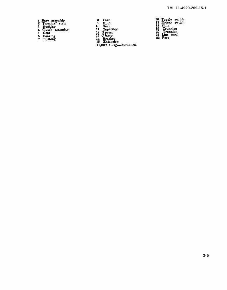
Fig. 3-1
Fig. 3-1
TM 11-4920-209-15-1
should be accomplished at the same time. The complished on a monthly basis are specified inmaintenance checks and services that are ac- paragraph 3-7.
3-5. Daily Maintenance Checks and Services Chart5LWTWW No. Item Procedure
1 Completeness _____________ See that the equipment is complete.2 Cleanliness --------------- Exterior of equipment must be clean
and dry; free of dirt, dust, grease,and fungus.
3 Level (top of table) ------ Glass on level should not be broken,the level should not be leaking, andthe level should indicate LEVELPOSITION.
4 Front panel switch _______ Set to L. Check for continuous leftrotation.
5 Front panel switch ------- Set to R. Check for continuous rightrotation.
6 Front panel switch ------- Set to OSC. Check that table rotationreverses direction every six cycles.Check that table rotates smoothwithout chatter.
3-6. Weekly Maintenance Checks and Services ChartSequence No. Item Procedure
1 Cables ------------------- Inspect cords and wires for chafed,cracked, or frayed insulation.
2 Metal surfaces ----------- Inspect exposed metal for rust andcorrosiqn. Clean and touch up paintas required.
3-7. Monthly Maintenance Checks and Services ChartSeqae8ce No. Item Procedure
1 Lubrication -------------- Lubricate the equipment ___________2 Terminal strip ___________ Inspect terminal blocks for loose con-
nections and cracked or broken in-sulation.
3 Publications --------------- See that all publications are complete,serviceable, and current.
4 Modifications ------------- Check DA Pam 310-7 to determine ifnew applicable MWO’S have beenpublished. All URGENT MWO’Smust be applied immediately. AllNORMAL MWO’S must be scheduled.
5 Spare parts ----------------- Check all spare parts for generalcondition and method of storage.No overstock should be evident andall storages must be valid requisi-tions.
Reference
Para 3-8
Fig. 3-1
Para 3-12
Para 3-12
Para 3-12
Reference
Para 3-9
Reference
Para 3-10
DA Pam 310-4
TM 38-750 and DA Pam 810-7
App. C
3-8. Cleaning Warning: Cleaning compound is flamma-
Inspect the exterior surfaces of the tilting ble and its fumes are toxic. Provide adequate
table. The exterior surfaces must be clean, ventilation. Do not use near a flame.
free of dust, dirt, grease, and fungus. b. Remove grease, fungus, and ground-ina. Remove dust and loose dirt with a clean dirt from the exterior of the tilting table. Use
soft cloth. a cloth dampened (not wet) with cleaning
3-2
compound. If dirt is difficult to remove, usemild soap if necessary.
3-9. Touchup Painting InstructionsRemove rust and corrosion from metal sur-faces by lightly sanding them with fine sand-paper. Brush two thin coats of paint on thebare metal to protect it from further corro-sion. Refer to applicable cleaning andrefinishing practices specified in TM 9-213.
3-10. lubricationa. Lubrication of the tilt head trunnions
must be performed each month and the tablebearing every six months. A month consistsof 30 days of normal 8-hour operation. Whenthe equipment is operated more than 8 hoursa day, adjust the lubrication intervals accord-ingly. For example, when the equipment isoperated 16 hours a day instead of 8, lubricatethe equipment every 15 days instead of everymonth.
b. To apply grease to the tilt head trunnions,
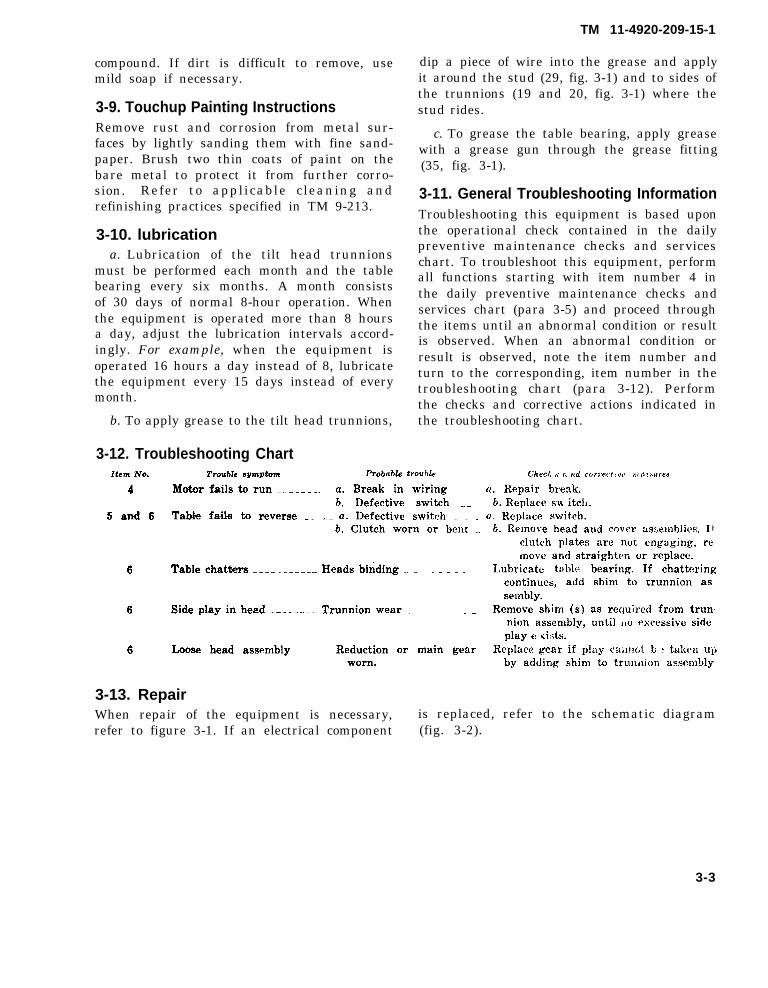
3-12. Troubleshooting Chart
TM 11-4920-209-15-1
dip a piece of wire into the grease and applyit around the stud (29, fig. 3-1) and to sides ofthe trunnions (19 and 20, fig. 3-1) where thestud rides.
c. To grease the table bearing, apply greasewith a grease gun through the grease fitting(35, fig. 3-1).
3-11. General Troubleshooting InformationTroubleshooting this equipment is based uponthe operational check contained in the dailypreventive maintenance checks and serviceschart. To troubleshoot this equipment, performall functions starting with item number 4 inthe daily preventive maintenance checks andservices chart (para 3-5) and proceed throughthe items until an abnormal condition or resultis observed. When an abnormal condition orresult is observed, note the item number andturn to the corresponding, item number in thetroubleshooting chart (para 3-12). Performthe checks and corrective actions indicated inthe troubleshooting chart.
Item No. Trouble avmptom Probable trouble G’hecl, s G ,,d c,,,-szwt.e;c j,) f?!! .,ure,g
4 Motor fails to run -------- a. Break in wiring _. _ {1. Repair break.b. Defective switch .._ b. Replace sw itch.
5and6 Table fails to reverse __ -_ a. Defective switch . . . U, Replace switch.b. Clutch worn or bent _. b. Remove head and cover assenlblies. It
SHIPMENT, LIMITED STORAGE, AND DEMOLITION TOPREVENT ENEMY USE
4-1. Repackaging for Shipment or limitedStorage
The exact procedure for repackaging dependson the material available and the conditionsunder which the equipment is to be shippedor stored. Adapt the procedures outlined belowwhenever circumstances permit. The informa-tion concerning the original packaging (para2-1) will also be helpful.
a. Material Requirements. The followingmaterials are required for packaging TiltingTable MX-4042A/ASW-12. For stock numbersof materials, refer to SB 38-100.
Packaging. Package the tilting table asb.outlined below.
(1) Cushion the tilting table on all sur-faces with pads of cushioning material.
(2) Place the cushioned unit within awrap of corrugated fiberboard.
(3) Secure the wrap with gummed tape.
(4) Place in waterproof barrier material.
(5) Secure with waterproof tape and cot-ton twine.
4-2. Authority for DemolitionThe demolition procedures given in paragraph4-3 will be used to prevent the enemy fromusing or salvaging this equipment. Demolitionof the equipment will be accomplished onlyunder the order of the commander.
4-3. Methods of DestructionThe tactical situation and time available willdetermine the method to be used when destruc-tion of equipment is ordered.
a. Smash. Use sledges, axes, hammers, crow-bars, and other heavy took available to smashthe unit.
b. Dispose. Bury or scatter destroyed partsor throw them into nearby waterways. Thisis particularly important if a number of partshave not been completely destroyed.
4-1
TM 11-4920-209-15-1
APPENDIX B
MAINTENANCE ALLOCATION
Section I. INTRODUCTION
B-1. GeneralThis appendix provides a summary of themaintenance operations covered in the equip-ment literature for Table, Tilting, Gyro In-strument Testing MX-4042A/ASW-12. It au-thorizes categories of maintenance for specificmaintenance functions on repairable itemsand components and the tools and equipmentrequired to perform each function. This ap-pendix may be used as an aid in planningmaintenance operations.
B-2. Explanation of Format for MaintenanceAllocation Chart
a. Group Number. Group numbers corre-spond to the references designation prefixassigned in accordance with ASY Y32.16,Electrical and Electronics Reference Designa-tions. They indicate the relation of listed itemsto the next higher assembly.
b. Component Assembly Nomenclature. Thiscolumn lists the item names of componentunits, assemblies, subassemblies, and moduleson which maintenance is authorized.
c. Maintenance Function. This column indi-cates the maintenance category at which per-formance of the specific maintenance functionis authorized. Authorization to performa function at any category also includes au-thorization to perform that function at highercategories. The codes used, represent thevarious maintenance categories as follows:
Code Maintenance category
C ----------------- Operator/crewO ----------------- Organizational maintenanceF ------------------ Direct support maintenanceH ------------------ General support maintenanceD ------------------ Depot maintenance
d. Tools and Equipment. The numbers ap-pearing in this column refer to specific toolsand equipment which are identified by thesenumbers in section III.
e. Remarks. Self-explanatory.
B-3. Explanation of Format for Tool andTest Equipment Requirements
The columns in the tool and test equipmentrequirements chart are as follows:
a. Tools and Equipment. The numbers inthis column coincide with the numbers used inthe tools and equipment column of the MAC.The numbers indicate the applicable tool forthe maintenance function.
b. Maintenance Category. The codes in thiscolumn indicate the maintenance category nor-mally allocated the facility.
c. Nomenclature. This column lists tools,test, and maintenance equipment required toperform the maintenance functions.
d. Federal Stock Number. This column liststhe Federal stock number.
e. Tool Number. Not used.
B-1
SECTION II.
GROUP NUMBER 1
TM 11-4920-209-15-1
B-2
SECTION III.
TM 11-4920-209-15-1
B-3
TM 11-4920-209-15-1
APPENDIX C
GS AND DEPOT REPAIR PARTS
Section I. INTRODUCTION
C-1. ScopeThis appendix contains a list of repair partsrequired for the performance of general anddepot maintenance for Table, Tilting, GyroInstrument Testing MX-4042A/ASW-12.
Note. No special tools, test, and support equipmentare required.
C-2. GeneralThe repair parts list is divided into the follow-ing sections:
a. Repair Parts for Direct Support, GeneralSupport, and Depot Maintenance, Section II.
Repair parts authorized for general supportand depot maintenance are included in this
section. No parts authorized for stockage atdirect support.
Note. All indexes noted below are cross-referencedto index numbers. The index numbers appear in as-cending sequence in column 1 of the repair parts list(para C-3a). The index number for the particular itemwill be the same for the item in all sections of thisappendix.
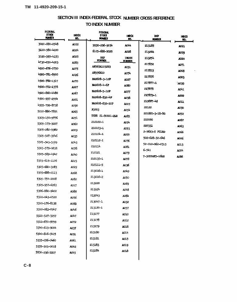
b. Federal Stock Number Cross-Reference toIndex Number, Section III. This is a cross-reference index of Federal stock numbers andmanufacturer’s part numbers to indexnumbers.
c. Reference Designation Cross-Reference toIndex Number, Section IV. This is a cross-reference index of reference designations and/or item numbers to index numbers.
C-3. Explanation of Columns~ explanation of the columns is given below.
a. Source, Maintenance, and RecoverabilityCodes (SMR) and Index Numbers Column.The first line in this column lists the applicable
SMR codes for the part. Listed in ascendingorder directly below the SMR codes is theindex number assigned to the repair part.
(1) Source code (S). The selection statusand source for the listed item is noted here.Source codes and their explanations are asfollows:Code ExplanationP - Applies to repair parts that are stocked
in or supplied from the GSA/DSA, orArmy supply system, and authorizedfor use at indicated maintenance cate-gories.
A - Applies to assemblies that are not pro-cured or stocked as such but are madeup of two or more units, each of whichcarries an individual stock numberand description and is procured andstocked and can be assembled by unitsat indicated maintenance categories.
X1 - Applies to repair parts that are not pro-cured or stocked, the requirement forwhich will be supplied by the use ofnext higher assembly or component.
X2 - Applies to repair parts that are notstocked. The indicated maintenancecategory requiring such repair partswill attempt to obtain them throughcannibalization; if not obtainablethrough cannibalization, such repairparts will be requisitioned with sup-porting justification through normalsupply channels.
(2) Maintenance code (M). The lowestcategory of maintenance authorized to installthe listed item is noted here.
Code ExplanationH ---------- General support maintenance
C-1
TM 11-4920-209-15-1
(3) Recoverability code (R). The infor-mation in this column indicates whether un-serviceable items should be returned for re-covery or salvage. Recoverability code and itsexplanation is as follows:
Note. When no code is indicated in the recover-ability column, the part will be considered expendable.Code Explanation
R - Applies to repair parts and assemblieswhich are economically repairable atDSU and GSU activities and normallyfurnished by supply on an exchangebasis.
b. Federal Stock Number Column. The Fed-eral stock number for the item is listed in thiscolumn.
c. Description Column. This column includesthe Federal item name and any additionaldescription of the item required, the manu-facturer’s part number (reference number),and the applicable five-digit Federal supplycode for manufacturers (para C-6). For sub-sequent appearances of the same item, themanufacturer’s code and part number (ref-erence number ) are omitted. The words “sameas” followed by the index number assigned tothe item when it first appeared in the list willfollow the item name, e.g., “RESISTOR,FIXED, COMPOSITION: SAME AS A298.”Usable on code column is not used.
d. Unit of Issue Column. The unit used as abasis of issue (e.g., ea, pr, ft, yd, etc.) is indi-
cated in this column.
e. Quantity Incorporated in Unit Pack Col-umn. Not used.
f. Quantity Incorporated in Unit Column.The quantity of repair parts in an assemblyis given in this column.
g. Maintenance Allowances Column.(1) The maintenance allowance columns
are divided into subcolumns. Indicated in eachsubcolumn opposite the first appearance of theitem is the total quantity of items authorizedfor the number of equipments supported. Sub-sequent appearances of the same item will haveno entry, in the allowance columns, but willhave a reference in the description column to
the first appearance of the item. Items author-ized for use as required, but not for initialstockage, are identified with an asterisk inthe allowance column.
(2) The quantitative allowances for Gcategory of maintenance will represent initi~stockage for a 30-day period for the number ofequipments supported.
h. One-Year Allowances Per 100 Equipments.Contingency Planning Purposes Column. Op-posite the first appearance of each item, thetotal quantity required for distribution andcontingency planning purposes is indicated.The range of items indicates total quantitiesof all authorized items required to provide foradequate support of 100 equipments for 1 year.
i. Depot Maintenance Allowance Per 100Equipments Column. This column indicates thetotal quantity of each item authorized depotmaintenance for 100 equipments. Subsequentappearances of the same item will have noentry in this column, but will have a referencein the description column to the first appear-ance of the item.
j. Illustrations Column.(1) Figure number (a). The number of
the illustration in which the item is shown isindicated in this column.
(2) Item No. or reference designation(b). This column lists the reference designa-tions that appear on the part in the equipment.
C-4. StockageNo parts authorized for stockage at organi-zational category.
C-5. Location of Repair Partsa. This appendix contains two cross-
reference indexes (sees. III and IV), to be usedto locate a repair part when either the Federalstock number, reference number (manufac-turer’s part number), or reference designa-tion is known. The first column in each cross-reference index is prepared, as applicable, innumerical or alphanumerical sequence. T}last column of each cross-reference index listhe index number assigned to the part.
b. Refer to the appropriate cross-reference
C-2
index (para C-2b and c), and note the indexnumber in the last column; then refer to therepair parts list to locate the index numberwhich is listed in ascending order in column 1of the repair parts list.
C-6. Federal Supply CodesThis paragraph lists the Federal supply codeand the associated manufacturer’s name.
Code Manufacturer
00481 ______ Asco Sintering Corp.07829 ______ Bodine Electric Co.15605 ______ Cutler-Hammer, Inc.30120 ______ Ideal-Aerosmith70270 ______ Alemite Corp.71002 ______ Birnbach Radio Co., Inc.
Code
71041 _____
71785 _____
72512 ______72653 ______72962 ______
73734 _____80205 ______
81073 ______82084 ______88044 ______96906 ______
TM 11-4920-209-15-1
ManufacturerBoston Gear Works Division of
Murray Co. of TexasCinch Mfg. Co. and Howard B.
Jones Div.Davies Harry Molding Co.G. C. Electronics Co.Elast i c Stop Nut Corp o f
SECTION II REPAIR PARTS FOR DIRECT SUPPORT, GENERAL SUPPORT, AND DEPOT MAINTENANCE(3)
DE3CR I PT I w
U3ABLE onIEFEREKC3 INMER i 16R. CODE COE
SCPEU, 2cUxm mm CAP:ISAS608-3-1OP; &P05
3’LYwlm2L : 22122 ; 30120
S22SC2WA : AS565A1032H3 ; W344
GRSR, SFWS : 213CW-1 ; 30120
cAPAC~R, FXSD : N3203 ;07829
Sclm, mclcm mm CAP:KAPAJ8-832-8P; m205
SPMTSS, SIWNS: 2121 U-5 ;3o120
CL4mP, W3R As7k2D5 ; e8044
2CRSW, 21EA3 CAP: NAS638-832-kP;80205
Sirrms h%mmY : 21TW7-l;30120
mRsw, SOCSST EmAll CAP:21AS6M-3-6P; 80205
2FWSEZ, 2HINH: 217878;yn2Q
~Bns SHAFT: 534 ;71.002
smmssu: NS565A6S12;
SHTI12S, 7wGI.2: 8363S7;M@
milmn, mTAsY: 5033-4;81073
SZ?J-, IAXK: 29-761; 15605
Rim, mcK =1087 ; 81o’T3
31m2: 213024; 3o120
PIATS, S~E : 213016-1; 3oLm
PIAT2, S~E: 213016-2; 30120
SC2SSIS, IWSIN3 : PJS505 -IS-6;
w MS3MILY, mm m:221885-3-18-&3; 3012C
IW2, S022Hi: 2t0103-l;3ols0
2CSW, I.mmm : 210102-1 ;3olm
X#, Kn2’ wmw: 2101OJ-1;3olm
mm, PI&n, ~2T:3s35650-3252; %SU6
m-‘n’; IN41T
—+
L
3
L
3
L
2
2
1
1
1
6
1
1
1
1
1
1
1
1
1
1
L1
1
4
4
1
4
a--la—
—
m--20—
●
*
●
●
*
—
5)-1-50—
●
+
*
,
*
—
(CONTINUED)
Ti-JPolJUTv PEcoVIP—
9
15
15
6
6
—
~10.—
—
uiTsAT 10N3(b)
TEM NO. ORREFERFNCEOESIGNATICW
cl
S1
S2
m
C-5
TM 11-4920-209-15-1
Tc%
INDIXNo.
x2-HA057
X2-H.4058
X2-HA059
x2-HA06C
P-HA(J6+
X2 -HAC@
x2-HA0,<3
x2-HA064
P-!iA065
xlA0b6
A-H-RA067
x2-HA068
X?-HAiJ69
P-HA070
X2-HA071
W-HAG72
X2-HAU73
X?-HAL17L
P-HAO’75
x1A076
x1A077
x1AW8
xlA079
[
x1A080
xlAb81
xlAU8?
xlA0a3
xlA084
JOU
STCCXNIMER
j305-57 $)-0838
j305- 175-3227
~355-056-rJ460
530j-282-598C
j305-17L, -3>27
j210-880 -7891
4920 -862. L48U
j305-@8-? 113
rw-782-1317
531 O-67C1 -9759
j305- 589-4942
b$120.r”7f.:750
5305 -75b-me
4730-050 -4,>03
SECTION II REPAIR PARTS FOR DIRECT SUPPORT, GENERAL SUPPORT, AND DEPOT MAINTENANCE(3)
OESCR I PTI OX
U3ABL[ 0sREFERENCE NMER & IFR . COOE COOE
C&E : 213120-1 ; 30120
SCRW, SOC~T HEAD CAP:NA,%38 -832-12P; $30205
HATS, INSTRUCTION : 213244;30120
SCREW, DRIV2: AN535 -O-3; 88044
XWB : 1919-2 ; 72512
SETSCREW : W AS AO09
PLATE, IDENT~ICATION: 222331;30120
SCREW. DRIVS: SANE AS A060
LEVEL, CYIJNDRICAL, CIRCULAR VAI :?-1 OG!L; 82084
SCREM, MACH~: 2-56X3-8 FILKO ;7373~
TABLS, INSTRMNT, TE3T : 217851 ;30120
Screw, 20CKST mAn CAP:NAs6J8-3-flP; 80705
ST1.M, SWIVEL: 2130.!0 ; 30120
CUP, S2.WNG: 213018; 301.2u
FT.4T2, IKM27CING : 217852 ;3012D
WHSR, TASLS CSNTSRlliG :210149; 30120
Xx2w, S9cm HP.A.D CAP:W AS A040
WASICJR, ICCK: AN93Gd1D ;88044
FEW ASS2MELY TABLR :210113-1; 30120
HSAO MSSMBLY : ?10112-1 ;30120
SCREW, SOC~T W CAP:IW3608-S-1:4P; 80205
PLATS, TOP: 210135-1;30120
SCRSW, WHIN2 : 210121 ;301;>0
SCR2W, SOCC3T mAD CAP:WS6U8-4 -6P; 8W.YJ5
2WT, STJP: :10114; 301,,c
2CIWW, SOCS3T lEAD cAP:NM6u8 -4-16P; 80?u5
FITTING, LUBRICATION:1641 ; 70,?70
SCRW mm ILJCK: 213043301, U
FrUHJ1
SSJE
—ea
ea
ea
ea
ea
ea
ea
ea
e.a
ea
e.
,s
ea
ea
,.
ea
,&
ea
ea
ea
..9
ea
ea
ea
,*
e.
.?*
,.
—
q‘Acx.
—
mH
—1
II
1
8
1
1
1
4
1
3
1
b
1
2
1
1
4
4
1
1
1
1
4
1
1
1
1
1
—
mI -5(—
—
a--la—
—
m.20—
●
●
●
●
—
T.5(—
●
*
●
●
—
m-1 YR
*!
—
5
5
5
4
—
( C O N T I N U E D )m:POTMTNmm
nllP—
7
2
5
1
—
(11)USTRATIOIIS
(b)Ttn no. OR
REFER[NCEOESIGIIATIM
C-6
TM 11-4920-209-15-1
310-17’6-8138
306-88Q-9W2
935-W9-873@
3bo-8L6-3425
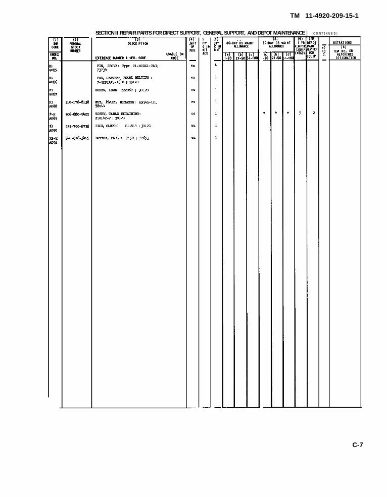
SECTlON II REPAIR PARTS FOR DIRECT SUPPORT, GENERAL SUPPORT, AND DEPOT MAINTENANCE
IEFERENCE IuMER k lfR. CODE CWE
PllS, GFQVE: ‘&P 21-80DXl-21G;73734
PAO, LFA!mER, ramm 22LTING :7-32DI.U5-161G i 301~
2C212W, ICCK 2’22&0 ; 30120
SUr, Fimi, mx.4wIi: m3k5-10;eaou
Zmlw, TABLE RmAnm&:210142-2 ; 30120
DIS& CLWX!H : 211614 ; 30120
21?lT31v, FZW3 : 1715c ; 72653
mmJT
i8JE
—
ea
ea
en
ea
4
ea
e.
—
5Int IllMITACK
—
. . ,30-D::t&M& I NT
( C O N T I N U E D )
T\G—
—
U5TRATIONS(b]
TEM MO. ORREFERFNCE
DESIGNATIIX
C-7
TM 11-4920-209-15-1
SECTION III INDEX-FEDERAL STOCK
FEDERALSTOCK
IHwBE~
I3020 -880-05b8
3110-580-4220
3=0-555-4153
W30-05M203
@2O-676-575O
4w0-781-8$n0
@o.782-1317
4920-782-1378
4920-860-4480
@20.937-25511
bq~5-T9cj-8T38
521O-MO-789L
5305-150-9776
5305-175-3227
5305-282-5~
5305-527-3746
5305 -$3-52;9
5305-579-0838
5305-589-4942
5305-615-1126
5305-(%0-3083
5305-688-2113
5305 -75!!-2008
5305-957-6263
5306-880-9402
5310-043-0520
5310-176-8138
5310-283-0947
53~0-527-3257
53L0-670-W59
5340-613-x)04
5340-816-3425
5355-056-0460
5355-503-0018
5930 -236-uM7
IIIDEX
t Ko.
A022
A024
A025
A083
A075
A026
AcY?o
ACQ7
A067
Aool
Aow
A065
A051
AC@
AO09
A035
A043
A058
Ad+O
A023
Ao29
A068
A082
A017
A089
A056
Ao8a
A046
A047
A072
A037
A091
Ao61
A042
A045
TO INDEX NUMBERNUMBER CROSS REFERENCE
FEDERALSTOCK
1S(MER No.
IIIOEK
5930-2%-5Q34
61os-688-swI
m?
AN56w032x3
AM936U0
MAs&M.3-12P
NAS608-4-6F
Iw608-5-12P
NAS608-832-4P
NAS608-832-1OP
2?3203
TYPE 21-8oDx.l-2LG
210102-1
210103-1
210104-1
21OU.2-1
21OII4
21OI.21
210135-1
212111-5
213016-1
213016-2
213020
213024
213043
213047-1
213120-1
213177
213178
213179
213180
213181
2131.83
213184
A044
A028
ImEx
A031
A074
Ao’27
A080
Am
A@
AO05
A034
A085
A054
A053
A055
A076
Ao81
A079
A078
A036
A049
A050
A@
A048
Ao84
A032
f@57
Aolo
A012
A016
A014
A015
A019
Ao18
m1
II(MER4
213185
21324
213254
2L7852
217853
217876
217&7-1
217878
217879-1
21W7-48
221.22
221885-3-18-8G
222060
222331
2-56x3-8 m
502-628-32-64.6
52-OI.2-062-0313
6-541
7-32DIAX5-16LG
I:ou
I i
A(321
A059
A020
Am
Aoo8”
AO03
IA039
A041
Aoo2
Aoll
A030
A052
A087
A063
AM
Aoo6
A013
AO04
ACM
C-8
TM 11-4920-209-15-1
SECTION IV INDEX-REFERENCE DESIGNATION CROSS REFERENCETO INDEX NUMBER
REFERENCE, OESKIIATIW ,
Bl
cl
al
82
TBl
ul
NtofJ
l-%A028
A034
A044
A045
AO04
Mm
REFERENCEOESIQMATIM
1 I
IXOEXMoo
t t
REFERENCE INOEXOESIO!IATION
AI t
C-9
TM 11-4209-209-15-1
By Order of the Secretary of the Army:
HAROLD K. JOHNSON,
Official:KENNETH G. WICKHAM,Major General, United States Army,The Adjutant General.
General, United States Army,Chief of Staff.
Distribution:
To be distributed in accordance with DA Form 12-36 requirements for Direct Support, OV-1A, OV-lB, OV-1C, CH-34A, CH-34C, CH-37B, CH-47A, UH-lB and UH-1D.
* U.S. GOVERNMENT PRINTING OFFICE 1983-764-028/6493
*U.S. GOVERNMENT PRINTING OFFICE : 1984 O - 421-302 (4450)
This fine document...
Was brought to you by me:
Liberated Manuals -- free army and government manuals
Why do I do it? I am tired of sleazy CD-ROM sellers, who take publicly available information, slap “watermarks” and other junk on it, and sell it. Those masters of search engine manipulation make sure that their sites that sell free information, come up first in search engines. They did not create it... They did not even scan it... Why should they get your money? Why are not letting you give those free manuals to your friends?
I am setting this document FREE. This document was made by the US Government and is NOT protected by Copyright. Feel free to share, republish, sell and so on.
I am not asking you for donations, fees or handouts. If you can, please provide a link to liberatedmanuals.com, so that free manuals come up first in search engines:
<A HREF=http://www.liberatedmanuals.com/>Free Military and Government Manuals</A>