17


Publisher: LuK GmbH & Co.Industriestrasse 3 • D -77815 Bühl/Baden
Telephon +49 (0) 7223 / 941 - 0 • Fax +49 (0) 7223 / 2 69 50Internet: www.LuK.de
Editorial: Ralf Stopp, Christa Siefert
Layout: Vera WestermannLayout support: Heike Pinther
Print: Konkordia GmbH, BühlDas Medienunternehmen
Printed in Germany
Reprint, also in extracts, withoutauthorisation of the publisher forbidden.

Foreword
Innovations are shaping ourfuture. Experts predict that therewill be more changes in the fieldsof transmission, electronics andsafety of vehicles over the next15 years than there have beenthroughout the past 50 years. Thisdrive for innovation is continuallyproviding manufacturers and sup-pliers with new challenges and isset to significantly alter our worldof mobility.
LuK is embracing these challen-ges. With a wealth of vision andengineering performance, ourengineers are once again provingtheir innovative power.
This volume comprises papersfrom the 7th LuK Symposium andillustrates our view of technicaldevelopments.
We look forward to some intere-sting discussions with you.
Bühl, in April 2002
Helmut Beier
Presidentof the LuK Group

Content
LuK SYMPOSIUM 2002
1 DMFW – Nothing New? . . . . . . . . . . . . . . . . . . . . . . . . . . . . . . . . . . 5
2 Torque Converter Evolution at LuK . . . . . . . . . . . . . . . . . . . . . . . 15
3 Clutch Release Systems . . . . . . . . . . . . . . . . . . . . . . . . . . . . . . . . 27
4 Internal Crankshaft Damper (ICD). . . . . . . . . . . . . . . . . . . . . . . . . 41
5 Latest Results in the CVT Development. . . . . . . . . . . . . . . . . . . . 51
6 Efficiency-Optimised CVT Clamping System . . . . . . . . . . . . . . . 61
7 500 Nm CVT . . . . . . . . . . . . . . . . . . . . . . . . . . . . . . . . . . . . . . . . . . 75
8 The Crank-CVT . . . . . . . . . . . . . . . . . . . . . . . . . . . . . . . . . . . . . . . . 89
9 Demand Based Controllable Pumps. . . . . . . . . . . . . . . . . . . . . . . 99
10 Temperature-controlled Lubricating Oil Pumps Save Fuel . . . 113
11 CO2 Compressors . . . . . . . . . . . . . . . . . . . . . . . . . . . . . . . . . . . . 123
12 Components and Assemblies for Transmission Shift Systems135
13 The XSG Family . . . . . . . . . . . . . . . . . . . . . . . . . . . . . . . . . . . . . . 145
14 New Opportunities for the Clutch?. . . . . . . . . . . . . . . . . . . . . . . 161
15 Electro-Mechanical Actuators. . . . . . . . . . . . . . . . . . . . . . . . . . . 173
16 Think Systems - Software by LuK. . . . . . . . . . . . . . . . . . . . . . . . 185
17 The Parallel Shift Gearbox PSG . . . . . . . . . . . . . . . . . . . . . . . . . 197
18 Small Starter Generator – Big Impact . . . . . . . . . . . . . . . . . . . . . 211
19 Code Generation for Manufacturing. . . . . . . . . . . . . . . . . . . . . . 225

27LuK SYMPOSIUM 2002
Clutch Release Systems
Matthias ZinkRené SheadRoland Welter
3

3 Clutch Release Systems
28 LuK SYMPOSIUM 2002
IntroductionNowadays, the link between the pedal and theclutch – the clutch release system – in pas-senger cars and small commercial vehicleswith a manual transmission is based almostexclusively on hydraulics. Despite being lessexpensive for initial installation, cable actua-tion systems have almost completely disap-peared from the market. The hydraulic systemis widely used because its hydraulic pressureline is easier to install in increasingly tighterpacked engine compartments (right- and left-hand drive), it is self-adjusting and allows theintegration of additional functions with little ex-penditure.
Through the use of hydraulic concentric slavecylinders, which have increasingly gainedmarket share in Europe since 1995, a greatsimplification in transmission assembly hasbeen achieved.
Further development of the hydraulic releasesystems currently focuses primarily on reduc-ing costs by using polymers instead of metal,for example, as well as on measures for in-creasing the actuation comfort while reducingthe pedal effort hysteresis and avoiding pedalvibrations [1].
In addition, the transition to polymers allowsadditional functions such as vibration damp-ing and peak torque limiting to be economi-cally integrated.
Furthermore, LuK has set a goal for itself todevelop new technological solutions by com-pletely rethinking of the ‘clutch and actuation’concept.
The first milestone on this path is to implementan ‘error-tolerant clutch system’.
Development Trends
Clutch Master CylinderThe housings for the first hydraulic clutch mas-ter cylinders were made of metal, which re-quires costly processing. Despite the intro-duction of plastic master cylinders the designpotential has not yet been fully exploited.
Fig. 1: Master Cylinder - Previous Design
Fig. 2: Master Cylinder – Current Design

3 Clutch Release Systems
29LuK SYMPOSIUM 2002
The piston and the seal tracks were made ofcase hardened metal. The connecting rodswere made of steel and the cylinders had nu-merous individual seals (figure 1).
In the meantime, LuK’s consistent develop-ment efforts have enabled to reduce by halfthe number of individual parts and largely toeliminate the use of costly metal parts(figure 2).
Operationally sound plastic seal tracks rein-forced by suitable material combinations andfibreglass thermoplastics are increasingly re-placing steel connecting rods.
By combining functions, the number of sealswas reduced from originally five to two.
The disadvantage of the light-weight plasticmaster cylinder housing is its tendency tosqueak, which is due to the speed-dependentfriction coefficient between the elastomerseals and the seal track.
In the meantime, effective countermeasureshave been developed for this problem. If asteel piston is used, a carbon coating is a veryeffective but somewhat costly solution. Alter-natively, LuK offers a piston made of a duro-plastic material. This allows the use of variousbrake fluids even under extreme climatic con-ditions without the occurrence of squeak.
Hydraulic Pressure Lines
Even though the hydraulic pressure lines areregarded as simple, off the shelf components,the necessity for cost reductions has led to nu-merous developments; in particular the quickfit connectors have undergone considerableimprovements. Current design solutions areshown in figure 3.
Fig. 3: Connector Technology
PA 12 plastic lines are becoming increasinglyimportant compared to steel / rubber assem-blies. Extensive use of these plastic lines isstill limited due to low durable operating tem-perature of around 120 �C, the temperaturedependence of the volume expansion and thepoor damping of pressure vibrations.
Significantly increased market penetration isexpected in the future as a result of new de-velopments, such as improved raw materialsand optimised extrusion methods (multi-layerpipes).
LuK as a full system supplier not only dealswith the line routing and its tuning, but is alsocommitted to further developing pressure linetechnologies with competent partners.
An example of this is the positioning of the con-nector within the cylinder housing; this en-sures increased functional safety of the jointbetween the line and the cylinder (figure 4).

3 Clutch Release Systems
30 LuK SYMPOSIUM 2002
This simplifies the line manufacture and, par-ticularly, the control processes during produc-tion. The functional test for the connection isconducted during the leakage test for the cyl-inder, which is a standard procedure.
Fig. 4: Integration of a Line Connector in the Cylinder
Slave CylinderWith hydraulic concentric slave cylinders(CSC), various functions are integrated into acompact unit that is easy to mount to the trans-mission.
Current concentric slave cylinderhousings are made of die cast orforged aluminium, which requirescostly processing and subsequentanodising treatment (figure 5).
The processing expense was re-duced by using injection mouldedhousings made of reinforced ther-moplastic material (figure 6).
The high temperature resistance ofthe selected material (polyphtala-mide, PPA) guarantees that the func-tionality and robustness of the plas-tic housing are comparable to cur-rent aluminium solutions. PPA ex-hibits outstanding medium compati-bility with regard to brake fluid andother materials in the engine com-partment.
Due to the advanced design of thehousing assembly, the expansionload between the guiding sleeve andthe housing is neutralised; thus theoperating load on the CSC mountingjoints is negligible (figure 7).
For example a release load of2000 N with the CSC design on theleft in figure 7 leads to an expansionload between the guiding sleeve andthe CSC housing of 4400 N (!). Thisforce needs to be borne by thethreaded joints.
The CSC design shown on the right complete-ly relieves the threaded joints.
The volume expansion of aluminium and plas-tic concentric slave cylinders is comparablefor temperatures up to 120 °C.

3 Clutch Release Systems
31LuK SYMPOSIUM 2002
Fig. 7: Avoidance of Expansion Load Housing / Guiding Sleeve
Fig. 5: CSC – Previous Design Fig. 6: CSC – Current Design

3 Clutch Release Systems
32 LuK SYMPOSIUM 2002
Fig. 8: CSC Volume Expansion
The slightly greater volume expansion of theplastic housing at higher temperatures can
easily be compensated by an appropriateclutch and actuation system design.
With the new housing material a new qualityof grease was introduced. This innovation pro-vides constant low friction during the entireservice life of the assembly.
The resulting low load and travel hysteresisare the prerequisite for exact clutch modula-tion in foot-actuated and automated clutchsystems.
LuK uses the full potential of the plastic designto increase the degree of functional integration.
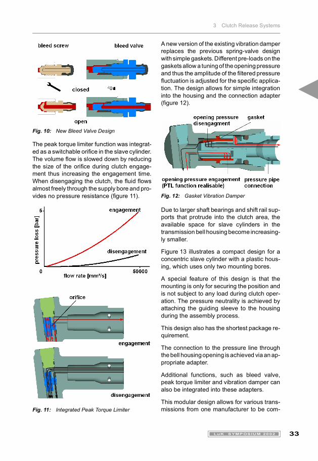
A two-stage bleed valve was developed for theplastic slave cylinder, which allows easy man-ual manipulation (without tools) during servic-ing (figure 10).
Fig. 9: Performance of Low Friction Grease
3 Clutch Release Systems
33LuK SYMPOSIUM 2002
Fig. 10: New Bleed Valve Design
The peak torque limiter function was integrat-ed as a switchable orifice in the slave cylinder.The volume flow is slowed down by reducingthe size of the orifice during clutch engage-ment thus increasing the engagement time.When disengaging the clutch, the fluid flowsalmost freely through the supply bore and pro-vides no pressure resistance (figure 11).
Fig. 11: Integrated Peak Torque Limiter
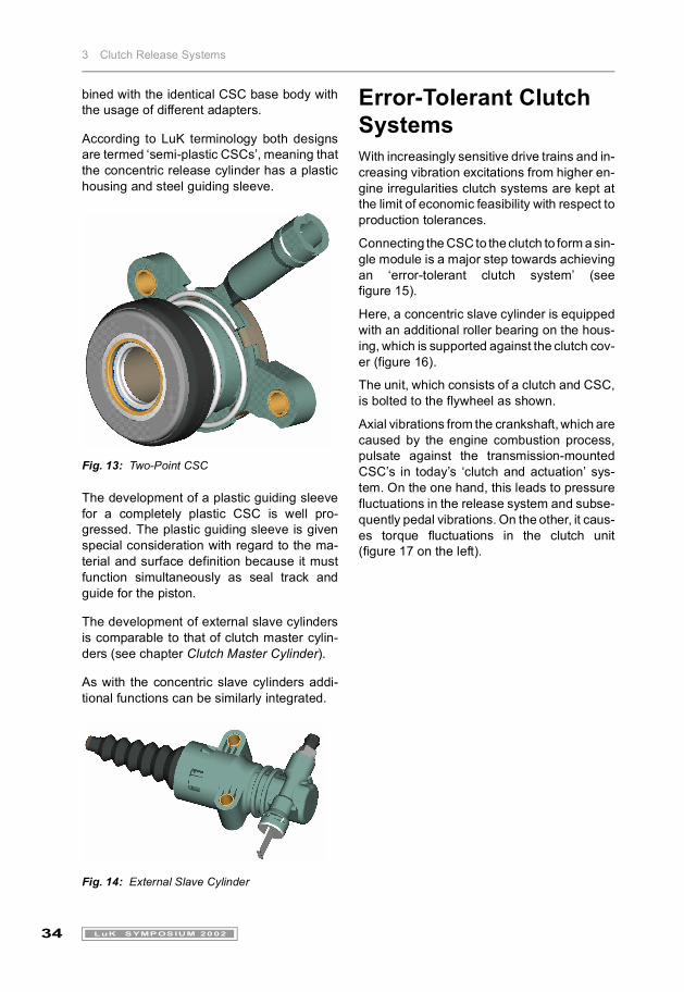
A new version of the existing vibration damperreplaces the previous spring-valve designwith simple gaskets. Different pre-loads on thegaskets allow a tuning of the opening pressureand thus the amplitude of the filtered pressurefluctuation is adjusted for the specific applica-tion. The design allows for simple integrationinto the housing and the connection adapter(figure 12).
Fig. 12: Gasket Vibration Damper
Due to larger shaft bearings and shift rail sup-ports that protrude into the clutch area, theavailable space for slave cylinders in thetransmission bell housing become increasing-ly smaller.
Figure 13 illustrates a compact design for aconcentric slave cylinder with a plastic hous-ing, which uses only two mounting bores.
A special feature of this design is that themounting is only for securing the position andis not subject to any load during clutch oper-ation. The pressure neutrality is achieved byattaching the guiding sleeve to the housingduring the assembly process.
This design also has the shortest package re-quirement.
The connection to the pressure line throughthe bell housing opening is achieved via an ap-propriate adapter.
Additional functions, such as bleed valve,peak torque limiter and vibration damper canalso be integrated into these adapters.
This modular design allows for various trans-missions from one manufacturer to be com-
3 Clutch Release Systems
34 LuK SYMPOSIUM 2002
bined with the identical CSC base body withthe usage of different adapters.
According to LuK terminology both designsare termed ‘semi-plastic CSCs’, meaning thatthe concentric release cylinder has a plastichousing and steel guiding sleeve.
Fig. 13: Two-Point CSC
The development of a plastic guiding sleevefor a completely plastic CSC is well pro-gressed. The plastic guiding sleeve is givenspecial consideration with regard to the ma-terial and surface definition because it mustfunction simultaneously as seal track andguide for the piston.
The development of external slave cylindersis comparable to that of clutch master cylin-ders (see chapter Clutch Master Cylinder).
As with the concentric slave cylinders addi-tional functions can be similarly integrated.
Fig. 14: External Slave Cylinder
Error-Tolerant Clutch SystemsWith increasingly sensitive drive trains and in-creasing vibration excitations from higher en-gine irregularities clutch systems are kept atthe limit of economic feasibility with respect toproduction tolerances.
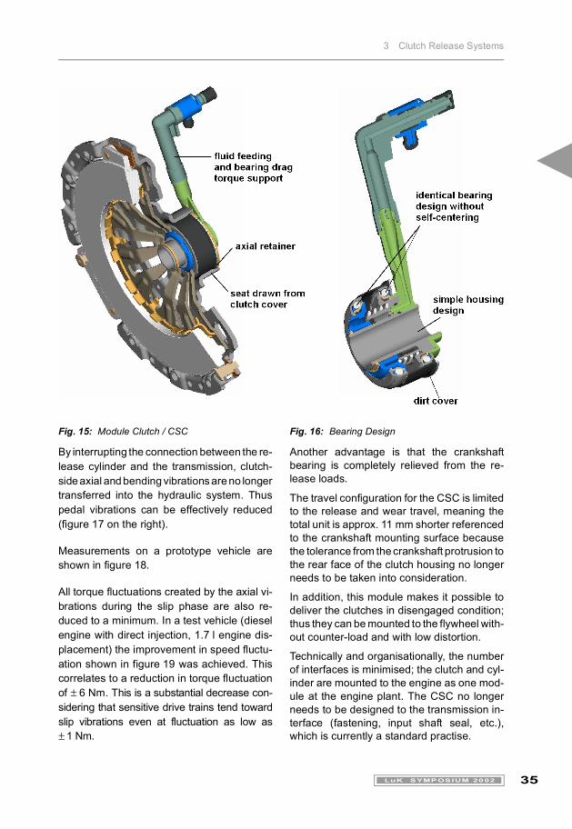
Connecting the CSC to the clutch to form a sin-gle module is a major step towards achievingan ‘error-tolerant clutch system’ (seefigure 15).
Here, a concentric slave cylinder is equippedwith an additional roller bearing on the hous-ing, which is supported against the clutch cov-er (figure 16).
The unit, which consists of a clutch and CSC,is bolted to the flywheel as shown.
Axial vibrations from the crankshaft, which arecaused by the engine combustion process,pulsate against the transmission-mountedCSC’s in today’s ‘clutch and actuation’ sys-tem. On the one hand, this leads to pressurefluctuations in the release system and subse-quently pedal vibrations. On the other, it caus-es torque fluctuations in the clutch unit(figure 17 on the left).
3 Clutch Release Systems
35LuK SYMPOSIUM 2002
By interrupting the connection between the re-lease cylinder and the transmission, clutch-side axial and bending vibrations are no longertransferred into the hydraulic system. Thuspedal vibrations can be effectively reduced(figure 17 on the right).
Measurements on a prototype vehicle areshown in figure 18.
All torque fluctuations created by the axial vi-brations during the slip phase are also re-duced to a minimum. In a test vehicle (dieselengine with direct injection, 1.7 l engine dis-placement) the improvement in speed fluctu-ation shown in figure 19 was achieved. Thiscorrelates to a reduction in torque fluctuationof � 6 Nm. This is a substantial decrease con-sidering that sensitive drive trains tend towardslip vibrations even at fluctuation as low as� 1 Nm.
Another advantage is that the crankshaftbearing is completely relieved from the re-lease loads.
The travel configuration for the CSC is limitedto the release and wear travel, meaning thetotal unit is approx. 11 mm shorter referencedto the crankshaft mounting surface becausethe tolerance from the crankshaft protrusion tothe rear face of the clutch housing no longerneeds to be taken into consideration.
In addition, this module makes it possible todeliver the clutches in disengaged condition;thus they can be mounted to the flywheel with-out counter-load and with low distortion.
Technically and organisationally, the numberof interfaces is minimised; the clutch and cyl-inder are mounted to the engine as one mod-ule at the engine plant. The CSC no longerneeds to be designed to the transmission in-terface (fastening, input shaft seal, etc.),which is currently a standard practise.
Fig. 15: Module Clutch / CSC Fig. 16: Bearing Design

3 Clutch Release Systems
36 LuK SYMPOSIUM 2002
Fig. 17: Torque Fluctuations

3 Clutch Release Systems
37LuK SYMPOSIUM 2002
Fig. 18: Performance in the Vehicle (see Legend Figure 19)
Fig. 19: Speed Fluctuations with Different Release Concepts
LuK tested the ease of transmission removalin various vehicles. Despite the increasedlength of clutch / CSC no installation conditionhas been found in which this module could notbe assembled.
By using a runout compensation release bear-ing, the clutch system achieves another de-gree of freedom. Geometrically induced jud-der in sensitive drive trains generated by highclutch finger runout can now be compensatedfor.
Active Clutch TorqueDriving students are not the only ones whohave complained about the difficulty of a con-trolled engagement action.
Experienced drivers have voiced the samecomplaint when they get into an unfamiliar ve-hicle. The low idle speeds and torques as wellas the practically ‘explosive’ torque curves fortoday’s diesel engines are difficult to modulateusing only clutch pedal and accelerator [2].
Who would not want a helping hand to auto-matically prevent the vehicle from stalling?
This is comparable to the ABS function thatavoids blocking of the wheels during brakingactions in extreme conditions or ESP, whichholds the vehicle in a curve despite excessivesteering.
To prevent stalling during launch, the launchaction is monitored and assisted if needed.The monitoring is performed by a control unit,using the signals that are already available(engine and wheel speeds, etc.); additionalsensors are not required. A control strategyevaluates the likelihood of stalling during start-up. If a critical condition is reached, the clutchengagement speed is restricted.
This task is performed by a solenoid valve inthe hydraulic release system which activelyreduces the pressure line diameter, therebyincreasing the flow resistance. This delays theclutch torque build-up and, if needed, evenbriefly stops it.
3 Clutch Release Systems
38 LuK SYMPOSIUM 2002
This system significantly reduces the risk ofstalling. During normal driving operations, thesystem is deactivated and not perceptible tothe driver.
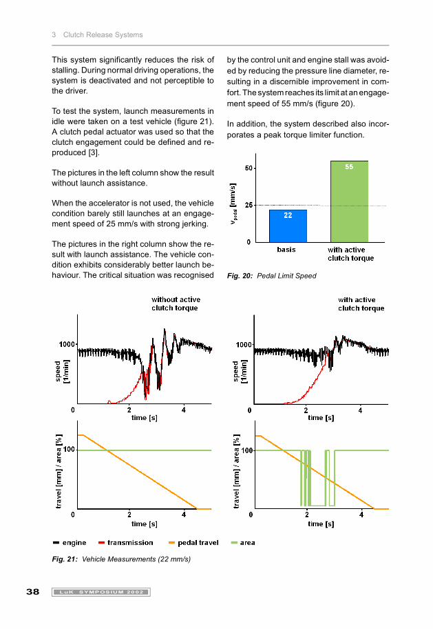
To test the system, launch measurements inidle were taken on a test vehicle (figure 21).A clutch pedal actuator was used so that theclutch engagement could be defined and re-produced [3].
The pictures in the left column show the resultwithout launch assistance.
When the accelerator is not used, the vehiclecondition barely still launches at an engage-ment speed of 25 mm/s with strong jerking.
The pictures in the right column show the re-sult with launch assistance. The vehicle con-dition exhibits considerably better launch be-haviour. The critical situation was recognised
by the control unit and engine stall was avoid-ed by reducing the pressure line diameter, re-sulting in a discernible improvement in com-fort. The system reaches its limit at an engage-ment speed of 55 mm/s (figure 20).
In addition, the system described also incor-porates a peak torque limiter function.
Fig. 20: Pedal Limit Speed
Fig. 21: Vehicle Measurements (22 mm/s)
3 Clutch Release Systems
39LuK SYMPOSIUM 2002
SummaryBy using plastic materials and more intelligentdesigns, cost savings can be attained forclutch actuation products, which seemed tohave reached their pinnacle. At the same time,the functionality has been expanded, thus in-creasing actuation and driving comfort.
The following solutions have been implement-ed for use in large scale production:
� Clutch master cylinder with duroplastic pis-tons to prevent noise
� Concentric slave cylinder with plastic hous-ing and neutralised expansion load
� Optimised bleed valve
� Integrated peak torque limiter
LuK emphasises the development of error-tol-erant systems in which the increased de-mands for driving and shifting comfort can beeconomically met.
� A module consisting of the clutch and theactuation unit
� An intelligent release system that can auto-matically compensate for errors duringclutch engagement
The expectation is that this Total System De-velopment will lead to completely new techni-cal solutions in the future.
References[1] Welter, Dr. R.; Zink, M.; Shead, R.:
Kupplungssysteme, ATZ-MTZ System-partner 2001, p. 42 - 47.
[2] Seebacher, R.; Zink, M.: Anfahrunter-suchungen mit Simulationsunterstüt-zung, Systemanalyse in der KFZ-An-triebstechnik, Expert-Verlag 2000.
[3] Zink, M.; Shead, R.: Clutch and Opera-tion as a System, 6th LuK Symposium1998.


