68
Final Presentation Phaedra Oikonomopoulou Mentors: Fred Veer Regina Bokel Pure Transparency Designing a complete glass shelter for the temple of Apollo Epikourios at Bassae

Final Presentation Phaedra Oikonomopoulou Mentors: Fred Veer Regina Bokel
Pure TransparencyDesigning a complete glass shelter for the temple of Apollo
Epikourios at Bassae

The temple
Quick Facts
Location: Bassae, Peloponesse, South Greece
Altitude: 1131 m
Date: 420-400 BC
Architect: Iktinos
Type: Doric Temple
Overall dimensions: 39.9 m x 16.1 m
Material: Local Gray Limestone
The first Greek Monument to be listed as UNESCO World Heritage [1986]
Final Presentation Phaedra Oikonomopoulou Mentors: Fred Veer Regina Bokel
LOCATION

Before and after


Why?
- The harsh weather conditions together with
- The nature of the main construction material, the local gray sedimentary limestone
- The wide external temperature range
- The intense seismic activity in the area
- The human pillaging- The foundation conditions of the temple.
Final Presentation Phaedra Oikonomopoulou Mentors: Fred Veer Regina Bokel

Assessment of the existing solution [Canopy]
Final Presentation Phaedra Oikonomopoulou Mentors: Fred Veer Regina Bokel
The temple is not visible from outside Leakages on the roof allow the water to penetrete The monument is always seen in subdued light

Objective
“Design a new shelter that protects the temple against the elements and at the same time it exhibits the monument by placing it into full view.”
Final Presentation Phaedra Oikonomopoulou Mentors: Fred Veer Regina Bokel

Objective
Transparency
Closed Shape
Minimalistic Design
Material Assessment
Cladding
Load-bearingStructure
Glass
Protect the temple from the elements (ice, rain)
Connect the monument with its Surroundings
Make it publicly visible
Minimize the temperature fluctuations Thermal Performance
Requirements Design Criteria Materialization
Final Presentation Phaedra Oikonomopoulou Mentors: Fred Veer Regina Bokel
}
}
}
}} }}

Points of Focus
Transparency
Closed Shape
Minimalistic Design
Material Assessment
Cladding
Load-bearingStructure
Glass
Protect the temple from the elements (ice, rain)
Connect the monument with its Surroundings
Make it publicly visible
Minimize the temperature fluctuations Thermal Performance
Requirements Design Criteria Materialization
Final Presentation Phaedra Oikonomopoulou Mentors: Fred Veer Regina Bokel
}
}
}
}} }}

Challenges
1. Architecture Combine ancient with high-tech architecture
2. Structure Such a large scale glass structure has never been realized before.
Demountable structure / Seismic Issues : Design a “moving” structure
3. Thermal Performance Protect the temple from ice formation / Minimize the temperature fluctuations
Optimize through passive systems
4. Sustainability Maintenance of the shelter
Final Presentation Phaedra Oikonomopoulou Mentors: Fred Veer Regina Bokel
Is such a structure possible?

Architectural Design
Final Presentation Phaedra Oikonomopoulou Mentors: Fred Veer Regina Bokel

Architectural Design
Final Presentation Phaedra Oikonomopoulou Mentors: Fred Veer Regina Bokel
Main Design Principles
1. Maximum Transparency 2. Proportions of the temple 3. Integration of the girder crane
4. Foundation restrictions 5. Sustainable Maintenance of the shelter

Architectural Design
Final Presentation Phaedra Oikonomopoulou Mentors: Fred Veer Regina Bokel

Architectural Design / Drawings
Final Presentation Phaedra Oikonomopoulou Mentors: Fred Veer Regina Bokel

Architectural Design
Final Presentation Phaedra Oikonomopoulou Mentors: Fred Veer Regina Bokel
North Facade

Architectural Design / Facade Division Modulus
Final Presentation Phaedra Oikonomopoulou Mentors: Fred Veer Regina Bokel
West Facade
East Facade

West Facade
East Facade
Final Presentation Phaedra Oikonomopoulou Mentors: Fred Veer Regina Bokel
Architectural Design / Impression

Final Presentation Phaedra Oikonomopoulou Mentors: Fred Veer Regina Bokel
Architectural Design / Impression

Final Presentation Phaedra Oikonomopoulou Mentors: Fred Veer Regina Bokel
Architectural Design / Impression


Structure
Final Presentation Phaedra Oikonomopoulou Mentors: Fred Veer Regina Bokel

Gloucestershire Country House Apple Store, 5th Avenue, NY
Final Presentation Phaedra Oikonomopoulou Mentors: Fred Veer Regina Bokel
Structure / Existing Glass Structures

Structure / Reinforced Glass Beams
1. Tempering process Increase of the (tensile) strength of the glass
Final Presentation Phaedra Oikonomopoulou Mentors: Fred Veer Regina Bokel
2. Over-dimensioning of the multiple glass layers that compose one glass beam
3. Stainless steel reinforcement bonded in the tensile zone along the edge of the glass beam.
Reinforced Glass Beams
Safety Measures for turning glass into a safe structural material:

Structure / Reinforced Glass Beams
1. Tempering process Increase of the (tensile) strength of the glass
Final Presentation Phaedra Oikonomopoulou Mentors: Fred Veer Regina Bokel
2. Over-dimensioning of the multiple glass layers that compose one glass beam
3. Stainless steel reinforcement bonded in the tensile zone along the edge of the glass beam.
Reinforced Glass Beams
Safety Measures for turning glass into a safe structural material: }Minimize the Probability of complete failure

Final Presentation Phaedra Oikonomopoulou Mentors: Fred Veer Regina Bokel

Structure / Reinforced Glass Beams
1. Tempering process Increase of the (tensile) strength of the glass
Final Presentation Phaedra Oikonomopoulou Mentors: Fred Veer Regina Bokel
2. Over-dimensioning of the multiple glass layers that compose one glass beam
3. Stainless steel reinforcement bonded in the tensile zone along the edge of the glass beam.
Reinforced Glass Beams
Safety Measures for turning glass into a safe structural material: }Minimizes the Consequences of complete failure

Final Presentation Phaedra Oikonomopoulou Mentors: Fred Veer Regina Bokel

Structure / Reinforced Glass Beams
Reinforced Glass Beams are a Composite Structure of: Structural Glass + Adhesive Interlayer + Steel Reinforcement
Final Presentation Phaedra Oikonomopoulou Mentors: Fred Veer Regina Bokel

Structure / Reinforced Glass Beams
Reinforced Glass Beams are a Composite Structure of: Structural Glass + Adhesive Interlayer + Steel Reinforcement
Final Presentation Phaedra Oikonomopoulou Mentors: Fred Veer Regina Bokel
Steel Reinforcement
Laminated Glass
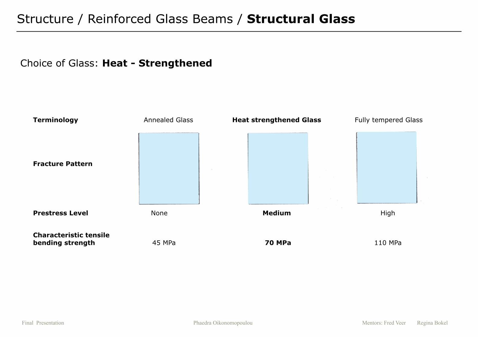
Structure / Reinforced Glass Beams / Structural Glass
Prestress Level None Medium High
Terminology Annealed Glass Heat strengthened Glass Fully tempered Glass
Fracture Pattern
Characteristic tensile bending strength 45 MPa 70 MPa 110 MPa
Choice of Glass: Heat - Strengthened
Final Presentation Phaedra Oikonomopoulou Mentors: Fred Veer Regina Bokel

Structure / Reinforced Glass Beams / Adhesive Interlayer
Choice of (foil) Interlayer: SGP (Du Pont’s Sentry Glass)
- The adhesive Interlayer:
keeps the glass fragments together in case of glass fracture
allows for an enhanced post-breakage behavior
- For structural glass two common interlayers: PVB and SGP
- SGP compared to PVB:
has 5 times higher tear strength
makes the laminated component 100 times more rigid
easily conforms to dimensional inaccuracies
Post-breakge behavior of laminated fully tempered glass: the frag-ments remain attached to the adhesive layer [TU Ghent]
PVB Interlayer: Before lamination, it has a rough surface (left side). When tempered for laminating, it becomes fully transparent (right side).
Final Presentation Phaedra Oikonomopoulou Mentors: Fred Veer Regina Bokel

Structure / Main Idea
Final Presentation Phaedra Oikonomopoulou Mentors: Fred Veer Regina Bokel
Monolithic Structural Behavior: Rib reinforced structure

Structure / Structural Elements
3. Structural Skin
The glass panes of the cladding function as a struc-tural skin that ties the structure together. These glass panes can be used as: 1. load-bearing elements for vertical loads2. bracing elements
2. Short Facades
The columns shape here is inverted to counteract the wind load.
1. Frame Structure
Consists of 19 glass frames tied together through the structural skin
Final Presentation Phaedra Oikonomopoulou Mentors: Fred Veer Regina Bokel

The shelter’s structure follows the same principles as the fuselage structure of airplanes in Aerospace Engineer-ing: A frame structure tied together through the structural skin.
Structure / From the air to the ground!
Final Presentation Phaedra Oikonomopoulou Mentors: Fred Veer Regina Bokel
“Ribs”
“Skin”

Structure / Buckling Resistance / Laboratory Testing
Final Presentation Phaedra Oikonomopoulou Mentors: Fred Veer Regina Bokel
����
07.06.12
Test reportCustomer : Job no. : Test standard : Type and designation of : Material : Specimen removal :
Specimen type : Pre-treatment : Tester : Notes... : Machine data :
Pre-load : 5 NTest speed : 1 mm/min
Test results:
NrσM εM d0 A0 Specimen no.
MPa % mm mm²1.1
�1.2�1.3
1.4
43,0 16,0 28,75 649,18 1- - 28,75 - 2- - 28,75 - 3
51,8 17,4 28,75 649,18 4
Series graph:
0 1 2 3 40
10000
20000
30000
Nominal compression in mm
Forc
e in
N
Statistics:
Seriesn = 2
σM εM d0 A0
MPa % mm mm²xsν
47,4 16,7 28,75 649,186,17 1,0 0,000 0,00
13,02 6,01 0,00 0,00
p haedra buckling glass.zs2 Page 1/1
Specimens: 1000 mm height, 4 mm thick

Structure / Buckling Resistance
Plain 4 mm glass T-profile 4 mmLoad: 2 tn, no buckling
T-profile 4 mmCritical Load: 3 tn
Buckling Test Results
Final Presentation Phaedra Oikonomopoulou Mentors: Fred Veer Regina Bokel

Structure / Dimensioning of the Structural Members
Final Presentation Phaedra Oikonomopoulou Mentors: Fred Veer Regina Bokel
Frameformed by two glass columns supporting a twin reinforced glass beam interlocked to the columns at both ends.
1. Main load-bearing structure glass beams and fins [d = 3x10 mm = 30 mm]
2. Structural skin Facade and roof glass panes
[d = 2x8mm +40 mm air + 2x8mm = 72 mm]
h=16 m
l=28m
30mm
72mm
90mm
2.7m

Structure / Calculations
Validating the whole structure under static and variable loads.
Location Direction in Model Peak Stresses Allowed Max. Strength (FoS=4)
Beam x 8 MPa (tension) 10 MPa (tension)
Column (fin) y 12 MPa (compression) 17 MPa (compression)
Plate Stress Intensity 4 MPa (tension) 10 MPa (tension)
2000 N/m2
1500 N/m2
Final Presentation Phaedra Oikonomopoulou Mentors: Fred Veer Regina Bokel

Structure / Key connections
The structure will function as a mechanical whole ONLY if the joints allow it.
The joints should be:
1. Strong but of negligible size [minimal intrusive]
2. Demountable [dry connection]
3. Allow for tolerances during the assembly process.
4. Avoid drilling of glass
Final Presentation Phaedra Oikonomopoulou Mentors: Fred Veer Regina Bokel

} Take advantage of the reinforcement: use it as a connector.
Composite material applied in aerospace enginnering
Structure / Key connections
The structure will function as a mechanical whole ONLY if the joints allow it.
The joints should be:
1. Strong but of negligible size [minimal intrusive]
2. Demountable [dry connection]
3. Allow for tolerances during the assembly process.
4. Avoid drilling of glass
Final Presentation Phaedra Oikonomopoulou Mentors: Fred Veer Regina Bokel

Structure / Demountable key connections
Connection between beam and fin
Final Presentation Phaedra Oikonomopoulou Mentors: Fred Veer Regina Bokel
1
2
3
4
Detail 4: Connection between finand glass panes
Detail 3: Vertical connection between glass panes
Detail 1: Connection between glass paneand supporting steel beam
Detail 2: Connection between fin and supporting steel beam

Structure / Earthquake
Measures against Earthquakes
1. Increase the strength of the building over-dimensioning: very heavy and expensive structure
2. Follow damage resistant principles Post - breakage ductile behavior
(laminated heat-strengthened glass has the highest level of fallout resistance)
3. Alter the building’s characteristics externally Base - Isolation (elastomeric bearings)
Lead Extrusion Dampers (LED)}
}
}
Final Presentation Phaedra Oikonomopoulou Mentors: Fred Veer Regina Bokel

Structure / Earthquake
The foundation should be leveled, so that the upper structure functions as a rigid box.
Final Presentation Phaedra Oikonomopoulou Mentors: Fred Veer Regina Bokel

Structure / Earthquake
Final Presentation Phaedra Oikonomopoulou Mentors: Fred Veer Regina Bokel
the columns have a trench along both sides covered by a grate

Structure / Conclusions
1. The proposed all glass structure can be realized
2. The slender dimensions of the elements are possible if the cladding is part of the load bearing structure.
3. Due to the monolithic behavior the structure can withstand buckling.
4. Joints are needed that visually do not obstruct, allow force transfer and provide structural safety.
Final Presentation Phaedra Oikonomopoulou Mentors: Fred Veer Regina Bokel

Thermal Performance
Final Presentation Phaedra Oikonomopoulou Mentors: Fred Veer Regina Bokel

Thermal Performance
Aim: Minimize the overall energy demand required to obtain thermal
comfort through passive strategies { material assessment
passive systems (e.g. natural ventilation)
Final Presentation Phaedra Oikonomopoulou Mentors: Fred Veer Regina Bokel

Thermal Performance
[Space Definition] : Semi-Outdoor Space
A space whose conditions are between indoor and outdoor location,which, however, can moderate the effects of the outdoor conditions.
In semi-outdoor spaces the occupants tend to tolerate a much wider tem-perature range than the ones determined based on the standard thermal comfort models.
Semi-Outdoor Space can be divided into 4 main categories:
1. Canopy / Buffer
2. Tempered Buffer
3. Partial Comfort
4. Full comfort
Outdoor Environment
Semi - Outdoor Environment
Indoor Environment
Occupied Zone
Personal / Task Zone
Layers of thermal environment surrounding a man[Nakano, 2003]
Final Presentation Phaedra Oikonomopoulou Mentors: Fred Veer Regina Bokel

Outdoor Environment
Semi - Outdoor Environment
Indoor Environment
Occupied Zone
Personal / Task Zone
Thermal Performance / Semi-Outdoor Space
Atrium Type Performance Level Application
Comfort Criteria
UK Japan
Winter Summer Winter Summer
Canopy
Buffer
Openess of outdoor set-ting reguired. Avoid rain
for activity within.
Links between buildingsCovered courtyard
Covered shopping center
Ambient AirTemperature - or 5 oC + due to solar gain
Ambient Tem-perature /
Peak air T = 30-35 oC
May range from outdoor level to indoor level due to concept
Tempered Buffer Semi-outdooor environ-ment for pleasure Passage, Agora
Air tempera-ture heated to 10 oC in occu-
pancy zone
As above approx. 18 oC 28 oC - out-door
Partial Comfort
Winter air conditioned. Shelter, shade, heating. Summer natural and or/mechanical ventilation.
Glazed LinksEntrances
Meeting halls
Air tempera-ture heated to 19 oC in occu-
pancy zone
As above(peak air
T= 30-35 oC)18-22 oC 26-28 oC
Full Comfort Normal Indoor Comfort Condition.
Lobby Exhibition Space
Enclosed shopping areasMeeting Space
19 oCMinimum max. 25 oC 22 oC 26 oC
Final Presentation Phaedra Oikonomopoulou Mentors: Fred Veer Regina Bokel

Thermal Performance / Defining the Requirements
[Space Definition] Semi-Outdoor Space
[Target Interior Temperature]
10-30 oC [margins]
[Type of Semi-Outdoor Space]
Partial Comfort} Comfort Zone[during occupancy hours]
10-30 oC [margins]
Final Presentation Phaedra Oikonomopoulou Mentors: Fred Veer Regina Bokel
Comfort Zone for occupancy hours
Temperature range for non - occupancy hours
[Problem Definition] Avoid FrostMinimize temperature fluctuations
[margins]
5 -30 oC
} }
}

Thermal Performance / Passive Strategies
Passive Strategies
- Aim is to minimize the overall energy demand to achieve thermal comfort through passive systems.
- Passive strategies focus on minimizing the risk of overheating.
[Summer] [Winter]
90 days 20-30 nights
Risk of overheating during daytime Risk of temperatures fall below 0 during night
Final Presentation Phaedra Oikonomopoulou Mentors: Fred Veer Regina Bokel

Thermal Performance / Passive Strategies
ENERGY DEMAND
Passive strategies
1. Utilize the thermal mass of the temple [limestone]
2. Natural Ventilation [solar chimney effect, earth ducts]
3. Coating Assessment [light transmission, U-value, reflectivity]
4. Shading [fritting]
heatingcoolinglighting } Environment: reduced energy
Owner: reduced cost}} Occupants: thermal comfort
visual comfort}
Final Presentation Phaedra Oikonomopoulou Mentors: Fred Veer Regina Bokel

Environment: reduced energyOwner: reduced cost
Thermal Performance / Passive Strategies
1. Thermal mass : Take advantage of the thermal mass of the temple
- Thermal mass is the ability of building materials to absorb heat, store it, and at a later time release it
- It reduces the fluctuations in temperatures
- It decreases the peak temperatures due to thermal inertia
- The surface of the thermal mass of the temple [limestone] was estimated to be approx. 2500 m2.
[Summer Period] During the day, the temple absorbs and stores heat from the hot air inside the shelter.
[Summer Period] At night, ventilation cools the shelter by releasing the heat absorbed in the limestone.
Final Presentation Phaedra Oikonomopoulou Mentors: Fred Veer Regina Bokel

Thermal Performance / Passive Strategies
2. Natural Ventilation
- Stack ventilation [Solar Chimney effect]
Cool air is pulled in from the bottom of the west facade and hot air is pushed out from openings at the top of the east facade
- Earth ducts
During winter outdoor air is preheated through heat exchange with soil and during summer it is cooled down through the same principle.

Thermal Performance / Material Assessment
[Roof] High reflective coating (> 25%)
+ 50% fritting (sun shading)
[Facades] Double glazing with low-e coating on the outer pane
+ gradient fritting: 0 -50%
Natural Ventilation Inlet
[fritting]
50% density
30% density
15% density
0% density
[Structure] Pilkington Optiwhite
Natural Ventilation Outlet
The roof angle together with the natural venti-lation helps to reduce hot air stagnation.
Final Presentation Phaedra Oikonomopoulou Mentors: Fred Veer Regina Bokel
3. Coating Assessment

Light Solar Energy Shading Coeffi-cient
U value
Application Type ofGlass
Tran
smitt
ance
Refle
ctan
ce
Direc
tTr
ansm
ittan
ce
Refle
ctan
ce
Abs
orpt
ance
Tota
l Tr
ansm
ittan
ce
Sho
rtW
avel
engt
h
Long
Wav
elen
gth
Tota
l
W/m
2K
Glass beams Facades and Roof’s
Inner pane
OptifloatClear8 mm
0.88 0.08 0.76 0.07 0.17 0.80 0.87 0.05 0.92 5.7
Facades’ outer pane
Optitherm S3based on 4mm outer pane with inner pane:
4mm Optifloat Clearand 16mm argon filled cavity
0.80 0.13 0,54 0.26 0.20 0.61 0.62 0.08 0.70 1.1
Roof’s outer pane
Suncool Silver 50/30based on 6mm outer pane with inner pane:
4mm Optifloat Clearand 16mm argon filled cavity
0.50 0.39 0.29 0.43 0.28 0.31 0.33 0.03 0.36 1.0
Glass finsOptiwhite
(heat-strengthened)10mm
0.91 0.08 0.88 0.08 0.04 0.89 - - - 5.6
Thermal Performance / Material Assessment
Final Presentation Phaedra Oikonomopoulou Mentors: Fred Veer Regina Bokel

Thermal Performance / Material Assessment
Outer Pane Cavity Inner Pane Fritting
SHGC / Total Solar Transmis-
sion
Direct SolarTransmis-
sion
Light Transmis-
sion
U-value(W/m2K)
Roof Pilkington Suncool HP Silver 50/30
16mm
Air40 mm
Pilkington Optifloat Clear
16mm50% 0,30 0,255 0,48 1,71
FacadesPilkington Optitherm
16mm
Air40 mm
Pilkington Optifloat Clear
16mm
0 - 50% (gradient) 0,52 0,44 0,74 1,76
Structure
Glass Pre-stressLevel
Tensile Strength Glass Type Thickness Adhesive Reinforce-
ment
Heat-Strengthened 70 MPa Pilkington Optiwhite
3 x 10 mm(30mm)
SGP Steel
Cladding > Thermal Comfort and Max. Transparency
Structure > Strength and Max. Transparency
Final Presentation Phaedra Oikonomopoulou Mentors: Fred Veer Regina Bokel

Thermal Performance / Material Assessment
Final Presentation Phaedra Oikonomopoulou Mentors: Fred Veer Regina Bokel

Thermal Performance / Fritting
4. Shading [Fritting]- reduces significantly the solar gain
- reduces glare
- enhances diffuse light (good for anaglyphs and monuments)
For the shelter:
[Gradient fritting]It starts from 0% and increases to 50% at the top of the facades and the roof. This is achieved by increasing the diameter of the dots.Through a gradient fritting a better blending into the environment is achieved. Example with gradient fritting: New Acropolis Museum, Athens, Tsumi
[White dots pattern]The pattern mast be simple, so that it will not create any complicated shadows that can distort the image of the monument. Therefore dots were chosen as the most appropriate solution.
The dots are white, so that they can reflect the light and not absorb it, overheating like this the glass surface.
Final Presentation Phaedra Oikonomopoulou Mentors: Fred Veer Regina Bokel

Thermal Performance / Fritting
Final Presentation Phaedra Oikonomopoulou Mentors: Fred Veer Regina Bokel

Passive systems only / Annual Hourly Simulation
Thermal Performance / Passive Systems contribution
- Max. Air Temperature = 37.3 oC / Max. Operative Temperture: 39.4 oC
- The operative temperature never falls below 0 oC [Min. Operative Temperature = 1.2 oC]
- The temple is fully protected from frost
- A supplementary mechanical unit is needed to always provide thermal comfort conditions for the visitors

Thermal Performance / Mechanical Supplementary Unit
Final Presentation Phaedra Oikonomopoulou Mentors: Fred Veer Regina Bokel
Heat pump + fan coils

Thermal Performance / Mechanical Supplementary Unit
Final Presentation Phaedra Oikonomopoulou Mentors: Fred Veer Regina Bokel
Passive + mechanical systems / Annual Hourly Simulation
- The supplementary energy demand can be covered by a 75 kW heat pump.
- However, only 17.3 % of the round year time needs the activation of the heat pump.
- Significantly smaller fluctuations: 5-30 oC instead of -9 - 37 oC

Sustainability / Self-cleaning ability of glass
Roof: with 10% inclination the rainwater cleans the roof
Facades:
Vindigo self-cleaning spray(applied once every year)
The rainwater drains through the surrounding trench.

Conclusions
The glass structure minimally distorts the view of the monument
Glass structure of uncommon slenderness
Cladding is part of the structural scheme
Monolithic structural behaviour
Joints are of great importance
The temple is protected from frost through the use of passive measures only
With a low energy consumption: a comfortable space for visitors is achieved
the temperature fluctuations are reduced
Final Presentation Phaedra Oikonomopoulou Mentors: Fred Veer Regina Bokel
[Architecture]
[Structure]
[Thermal Performance]

Large transparent enclosures for monuments that need to be protected are possible!!!!
Thank you!


