PWB Back Drilling Failure Analysis
Project Lead: PC Wong, PWB Interconnect
Solutions, Inc.
Project Facilitator: John Davignon, HDP
Duren Meeting: June 4, 2014
Project: Definition Stage
© 2014 HDP User Group International, Inc. All rights reserved 1
Project Background
• Back drilling or controlled depth
drilling of plated through holes (PTH)
is increasingly being used in High
Speed Designs.
• While back drilling of PWBs helps to
remove signal distortion by removing
via related stubs, reliability issues
attributed to this practice appear to
be on the rise.
© 2014 HDP User Group International, Inc. All rights reserved 2
The critical parameter is
the length of remaining
copper via (Stub) from
the targeted inner layer
pad
The Signal Integrity Issue
© 2014 HDP User Group International, Inc.
All rights reserved
3
Project Drivers/Gaps
• Both the number of back drilled vias and
the variation of depths (any & all layers)
are increasing on each board.
• Design Rules are driven by Electrical
requirements, not necessarily based on
PWB reliability data or fabrication
capabilities.
© 2014 HDP User Group International, Inc. All rights reserved 4
Products Using Back Drilling
© 2014 HDP User Group International, Inc. All rights reserved 5
Blue shows the 3584 holes in the device.
Red shows 1142 are back drilledIncreasing
numbers of
designs specify
multiple levels
of back drilling
throughout the
construction
120 mils thick with backdrills down to 94 mils from both sides
Purpose of Project
• Quantify the reliability of specific backdrill
holes designs compared to PTH holes
• Quantify the relative reliability of shallow,
medium and deep backdrill holes.
• Quantify the influence of hole size, pad
size and pitch on backdrill hole reliability
(0.032”, 0.040” and 0.080” pitch).
• Develop evaluation coupons and
methodology for both depth and stub
measurement by electrical means© 2014 HDP User Group International, Inc. All rights reserved 6
Project Scope
• This project will baseline back drilling reliability
and capability of high layer count boards for
datacom, telecom & backplane products and to
identify potential solutions and design guidelines
to prevent future problems.
• This is not a laminate materials, drilling
equipment, fabrication process or signal integrity
study.
• This will be accomplished in 3 proposed parts
– Part 1: Survey
– Part 2: Reliability / Capability testing
– Part 3: Guideline documentation
© 2014 HDP User Group International, Inc. All rights reserved 7
Objective/Strategy
• Design a Test Vehicle with coupons to measure the
capability & reliability baseline of back drilling
• Modify an existing 20 layer, 1/2oz copper, FR4 based
stack-up Test Vehicle. (Pb-free PWB Materials Reliability
Project)
• Send out the design to OEM members for support in
building this TV
• Build the TV at various PCB Fabricator sites
• Test/Evaluate the coupons to measure and establish
an Industry baseline for capability & reliability
• Publish the results of the baseline both internally and
externally at industry conferences
© 2014 HDP User Group International, Inc. All rights reserved 8
Deliverables
• Publish results of backdrill OEM/PWB survey
on capability and requirements.
• Publish a report documenting the measured
stub length and depth control using our TV.
• Publish a report documenting the reliability of
various backdrill design features.
• Publish a BD design guideline report
• A Backdrill Test Vehicle for future phases and
use in the industry to verify backdrilling
capabilities and reliability
© 2014 HDP User Group International, Inc. All rights reserved 9
Benefits/Impact
© 2014 HDP User Group International, Inc. All rights reserved 10
A set of design parameters for HDP members that will
guide OEM, ODM, system designers in designing a more
reliable back drill product. These design guidelines will
help reduce development cost for redesigns and improve
TTM.
Provide coupon design and methodology to electrically test
backdrill holes. This methodology will save the OEM/PWB
fabricator money in post build inspection.
Provide PWB fabricators and equipment suppliers with the
future backdrill technology direction for high end, high
layer count products in the data/tele com sector. This
direction will allow strategic capital investment to align with
future requirements.
Technical Discussions
© 2014 HDP User Group International, Inc. All rights reserved 11
Test Vehicle / Coupons
There will be 7 different coupons on the TV
PWB Interconnect Solutions:
• Modified IST coupons for reliability (3 designs)
• New Thickness/Depth Measurement
Introbotix:
• Stub Length Measurement
• Backdrill Depth Verification (Microsection)
© 2014 HDP User Group International, Inc.
All rights reserved
12
© 2014 HDP User Group International, Inc. All rights reserved13
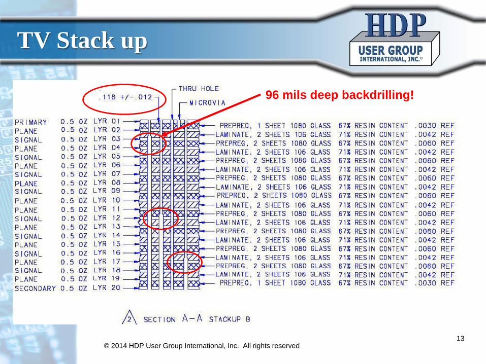
TV Stack up
96 mils deep backdrilling!
PWB Solutions TV Objectives
© 2014 HDP User Group International, Inc. All rights reserved 14
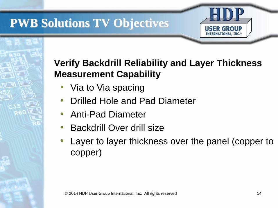
Verify Backdrill Reliability and Layer Thickness
Measurement Capability
• Via to Via spacing
• Drilled Hole and Pad Diameter
• Anti-Pad Diameter
• Backdrill Over drill size
• Layer to layer thickness over the panel (copper to
copper)
© 2014 HDP User Group International, Inc. All rights reserved 15
PWB DOE/TV Coupons
Coupon Via to Via Spacing
Drilled Hole Diameter
Pad Diameter
Anti-Pad Diameter
Over-Size Drill Diameter
1A 0.032” 0.010” 0.019” 0.026” 0.018”
1B 0.040” 0.010” 0.022” 0.030” 0.018”
2 0.080” 0.026” 0.038” 0.046” 0.034”
Back-drilling will accommodate 3 levels –
“Shallow” L2 or L3, Middle L10 or L11, “Deep”
L18 or L19.
Each pair of back-drilled holes will be
surrounded by traditional plated through holes.
Each coupon design will have two “sections” –
1) PTH, 2) PTH with back-drilled vias
interspersed.
Each back-drill depth with be an independent
coupon design (3 design types * 3 depths = 9
coupon designs)
B
B = Back-drilled hole
Representing typical diff pair
BB
B
Laminate Thickness/Depth Coupon
© 2014 HDP User Group International, Inc. All rights reserved 16
- Coupon uses capacitance
measurements to determine
the dielectric thickness /
depth.
- Capacitance plates are
sequenced per the diagram
on the left to minimize the
size of the coupon.
© 2014 HDP User Group International, Inc. All rights reserved
17
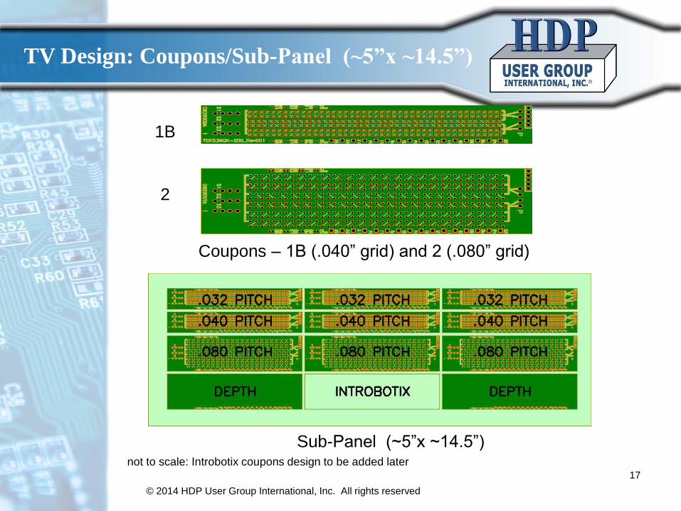
TV Design: Coupons/Sub-Panel (~5”x ~14.5”)
not to scale: Introbotix coupons design to be added later
1B
2
Sub-Panel (~5”x ~14.5”)
Coupons – 1B (.040” grid) and 2 (.080” grid)
Introbotix TV Objectives
© 2014 HDP User Group International, Inc. All rights reserved 18
Verify Test and Measurement Equipment Capability
• 50GHz loss measurement probing on backplane
structures with point to point trace routing on
differential pairs.
• Smallest stub length that can be detected (e.g., 4
mil)
• Test system stub length resolution (e.g., 2mil)
• Test system accuracy by correlation to micro-
sections
Stub Length on Loss
© 2014 HDP User Group International, Inc. All rights reserved19
Loss measurement with 0 mil stub.
Resonance beyond 40GHz
Thickness: 91 mil
Drilled Via: 10mil
Routing 20 layer
L1 to L3: 30mil
Ack: Introbotix, Inc.
Stub Length on Loss
© 2014 HDP User Group International, Inc. All rights reserved20
50 mil stub,
24Ghz
61 mil stub,
20 GHzThk: 91 mils
Via: 10mil
BD: 19mil
20 layer
L1 - L3: 30 mil
30 mil stub,
30 GHz
10 mil stub,
30+ GHz
Ack: Introbotix, Inc.
Introbotix Coupons
© 2014 HDP User Group International, Inc. All rights reserved 21
Microsection Validation Coupon
Incremental Backdrill Length Coupon – Trace Length: 3.5inches
– Land G-S-S-G with 32mil via pitch
– PTH diameter: 10mil
– Oversize Backdrill diameter determined
by fabricator
– 15 traces with BD length varying from -
4mil passed routing layer, -2mil passed
routing layer, 0mil, +2mil to routing layer,
+4,+6,+8+10,+12+,14+,16,+18,+20,+24,
+35
– Note: -4mil, -2mil is designed to be
overdrilled with possibility that
manufacturing process may underdrill
and achieved desired short stub
– Target line width/spacing(mils): 6/7/6
(target differential impedance is
100ohms +/-10%)
Expected DOE Results
–Reliability of the 3 depths vs. PTH (with and without
assembly thermal stress)
–Reliability of backdrill geometry (coupon design
geometry)
–Reliability of PCB source (relative to peers who
submitted samples)
–Variation of backdrill depth in relation to position on
panel
–Correlation of depth control measurement methods
–Electrically quantifying/measuring true depth of no-
cut layer (how deep fabricators need to go)
–Electrically determine if any copper on sidewall or
copper debris in hole remains© 2014 HDP User Group International, Inc. All rights reserved 22
© 2014 HDP User Group International, Inc. All rights reserved 23
Task Resource Complete Date
Survey – develop, consolidation and analysis
Cray / Oracle 3Q2014
TV – design, review and release for fabrication
PWB / Introbotix 3Q2014
TV – fabrication ISU Petasys 3Q2014
TV – As received testing and data analysis
PWB /Introbotix 1Q2015
Simulated Assembly Reflow Flextronics 4Q2014
TV – After reflow testing and data analysis
PWB /Introbotix 1Q2015
Report – writing, editing and release PWB / Team
Phase 1 Survey PWB 1Q2015
Phase 2 Reliability & Capability PWB 2Q2015
Phase 3 Guideline PWB 3Q2015
Resources Committed/Timeline
Team Members
© 2014 HDP User Group International, Inc. All rights reserved24
• PC Wong, Project Lead,PWB
Interconnect Solutions
• Joe Smetana, Alcatel-Lucent
• Paul Brown, Alcatel-Lucent
• Richard Coyle, Alcatel-Lucent
• Thilo Sack, Celestica
• James Armstrong, Ciena
• Mike Wingrove, Ciena
• David Wice, Ciena
• Ivan Straznicky, Curtiss-Wright
• Paul Wenaas, Cray
• Al Ortiz, Ericsson
• Igor Perez-Uria, Ericsson
• Ove Isaksson, Ericsson
• Akiko Matsui, Fujitsu
• Brian Smith, HDP
• Marshall Andrews, HDP
• John Davignon, HDP
• Brandon Sherrieb, Integrated Test
(ITC)
• Dana Freeman, Integrated Test (ITC)
• Brian Butler, Introbotix
• Girish Wable, Jabil
• Leif Hutchinson, Juniper
• Mike Freda, Oracle
• Karl Sauter, Oracle
• Bill Birch, PWB Interconnect
• Dan Turpuseema, RD Circuits
• Mulugeta Abtew, Sanmina
• Kevin Zhang, Sytech
• Tarja Rapala, TTM
• Marika Immonen, TTM
• Timo Jokela, TTM
• Alan Cochrane, TUC
Back-up Slides
© 2014 HDP User Group International, Inc. All rights reserved 25
Goals
• Publish the results of where the OEM’s
are going with backdrill designs
• Determine the tolerance and variation
of stub length and depth control
through a specially designed test
vehicle
• Quantify the reliability of backdrill vias
at varying depths – short, medium and
long through a specially designed test
vehicle
© 2014 HDP User Group International, Inc. All rights reserved 26
Backdrill challenges
• Holding very tight stub length tolerances
(less than 10 mils from the signal trace).
• Accurate calculation of back drill depths.
• For fine pitch devices the back drilling
cannot be done due to over sizing of the
secondary drill.
• Board thickness variation from the center
to the edges due to design and/or
lamination process.
© 2014 HDP User Group International, Inc. All rights reserved27
Examples of OEM/ODM Survey
• Are you designing with backdrilled subpanels?
• Are you backdrilling from both sides of the panel?
• How many depths/levels do you drill on a panel?
• How dense is your backdrill area (via’s per cm2)?
• What pitch are you backdrilling? (1mm to .4mm)
• What size of over-drill do you design for? (initial
drill + XX mils)
• What is the limit by design on the minimum stub
length removal? (What length of via would you not
remove?)
© 2014 HDP User Group International, Inc. All rights reserved28
© 2014 HDP User Group International, Inc. All rights reserved 29
Coupon Fabrication / Testing Matrix
Description Quantity
Number of production panels :IdealMinimum
12
6
Number of unique coupon designs per sub-panel ( 3 depths x 3 grids ) + 1x Introbotix coupon + 2x BD coupon
12
Total number of couponsIdeal (12 production panels x 4 subpanels x 12 coupon designs)Minimum (6 production panels x 4 subpanels x 12 coupons designs)
576
288
Quantity per coupon design :IdealMinimum
48
24
Capacitance Measurements:“As-received”Preconditioning using reflow ovenPreconditioning using IST
8
8
8
IST testing (after capacitance measurements) 24
Project Scope: Three Part Project
• Part 1: Assessing the backdrill situation in the
Industry through a 1:1 survey. All inputs will be
company coded to keep all data anonymous.
– OEM/ODM Survey to document what design
tolerances/stub lengths are being designed into
products now and 3 years into the future.
– PWB Fabricator Survey to document what problems
manufacturers see in supporting the level of
technology/tolerance and what would be needed to
comply with the requirements.
© 2014 HDP User Group International, Inc. All rights reserved 30
Project Scope: Three Phase Project
• Part 2: Test and verify the reliability and
capabilities of backdrill designs. This will be done
by designing electrically tested coupons and test
vehicles that will be built and tested by the project.
(micro-sectioning only as needed to verify ET
results)
• Part 3: Develop a realistic set of design
guidelines based on reliability data for the OEM
designs.
© 2014 HDP User Group International, Inc. All rights reserved 31
Project Flow Chart
Finalize Scope
Part 1: Survey
Finalize Survey
QuestionsConduct
PWB Survey
Consolidate &
AnalysisPublish Results
Finalize Project
ObjectivesFinalize Test
Plan Finalize DOEBOD Approval
Implementation
Part 2: Reliability / Capability Testing
Conduct
ODM/OEM
Survey
TV design, review
and release for
fabrication
TV “as rec’d” and
“after reflow cycle”
testing
Failure Analysis Publish ResultsTV fabrication
Part 3: Guidelines
Review Survey
Results
Create Design
Guidelines using
Survey & TV Results
Final ReportReview TV
Results
© 2014 HDP User Group International, Inc. All rights reserved 32