THE SOC Q QUY CHU THIẾT BỊ TRẠM GỐ National technical r CIALIST REPUBLIC OF VIETNAM QCVN 14:2010/BTTTT UẨN KỸ THUẬT QUỐC GIA VỀ ỐC THÔNG TIN DI ĐỘNG CDMA regulation on Cellular Mobile CDMA Base Station Equipment (for information only) HANOI - 2010 A 2000–1X A 2000–1x
Transcript
THE SOCIALIST REPUBLIC OF VIETNAM
QCVN
QUY CHUTHIẾT BỊ TRẠM GỐC
National technical regulation on
THE SOCIALIST REPUBLIC OF VIETNAM
QCVN 14:2010/BTTTT
QUY CHUẨN KỸ THUẬT QUỐC GIA VỀ ỐC THÔNG TIN DI ĐỘNG CDMA 2000
National technical regulation on Cellular Mobile CDMA 2000
Base Station Equipment
(for information only)
HANOI - 2010
CDMA 2000–1X
Mobile CDMA 2000–1x
QCVN 14:2010/BTTTT
2
Table of contents
Foreword
1. GENERAL ............................................................... Error! Bookmark not defined.
1.1. Scope ............................................................... Error! Bookmark not defined.
1.2. Subjects of application ..................................... Error! Bookmark not defined.
1.3. Definitions and Abbreviations ....................... Error! Bookmark not defined.
2. TECHNICAL REQUIREMENTS .............................. Error! Bookmark not defined.
3. MANAGEMENT REGULATIONS ............................ Error! Bookmark not defined.
4. RESPONSIBILITY OF ORGANISATIONS/INDIVIDUALS ..... Error! Bookmark not
defined.
5. IMPLEMENTATION ................................................ Error! Bookmark not defined.
QCVN 14:2010/BTTTT
3
QCVN 14:2010/BTTTT
4
Foreword
QCVN 14:2010/BTTTT is based on the review and convert of TCN 68-223:2005 "Cellular mobile CDMA 1X base stations-Technical requirements", issued by decision no 28/2005/QĐ-BBCVT dated August 17, 2005 of Minister of Ministry of Post and Telecommunications (now the Ministry of Information and Communications).
Technical Requirements of QCVN 14:2010/BTTTT accordance with standard C.S0010-A/B: “Recommended Minimum Performance Standards for cdma2000 Spread Spectrum Base Stations” of 3rd Generation Partnership Project 2 (3GPP2).
QCVN 14:2010/BTTTT is drafted by Research Institute of Posts and Telecommunications (RIPT), verified and submitted by Department of Science & Technology, issued by the Minister of Information and Communications as in Circular No 18/2010/TT-BTTTT dated July 30, 2010.
QCVN 14:2010/BTTTT
5
QCVN 14:2010/BTTTT
6
QUY CHUẨN KỸ THUẬT QUỐC GIA VỀ THIẾT BỊ TRẠM GỐC THÔNG TIN DI ĐỘNG CDMA 2000-1X
National technical regulation on Cellular Mobile CDMA 2000-1x
Base Station Equipment
1. GENERAL
1.1. Scope
This technical regulation specifies minimum performance characteristics, definitions and methods of measurement for Cellular Mobile CDMA 2000 1X Base Stations that operate in the bands: 450 MHz, 800 MHz and 2 GHz.
1.2. Subjects of application
This technical regulation applies to all agencies, organizations, manufacturers, importers and operators of Cellular Mobile CDMA 2000 1X Base Stations that operate in the bands: 450 MHz, 800 MHz and 2 GHz.
1.3. Definitions and abbreviations
In this technical regulation, the terms, abbreviations below are construed as follows:
1.3.1. Access Attempt.
A sequence of one or more access probe sequences on the Access Channel or
Enhanced Access Channel containing the same message.
1.3.2. Access Channel
A Reverse CDMA Channel used by mobile stations for communicating to the base
station. The Access Channel is used for short signaling message exchanges, such as
call originations, responses to pages, and registrations. The Access Channel is a
slotted random access channel.
1.3.3. Access Channel Preamble
The preamble of an access probe consisting of a sequence of all-zero frames that is
sent at the 4800 bit/s rate
1.3.4. Access Probe
One Access Channel transmission consisting of a preamble and a message. The
transmission is an integer number of frames in length, and transmits one Access
Channel message. See also Access Probe Sequence and Access Attempt.
1.3.5. Access Probe Sequence
A sequence of one or more access probes on the Access Channel or Enhanced
Access Channel. The same Access Channel or Enhanced Access Channel message
is transmitted in every access probe of an access attempt. See also Access Probe,
Enhanced Access Probe, and Access Attempt.
QCVN 14:2010/BTTTT
7
1.3.6. Active Frame
A frame that contains data and therefore is enabled in terms of traffic power.
1.3.7. Adjacent Channel Leakage Ratio.
The ratio of the on-channel transmit power to the power measured in one of the
adjacent channels.
1.3.8. AWGN
Additive White Gaussian Noise.
1.3.9. Base Station
A fixed station used for communicating with mobile stations. Depending upon the
context, the term base station may refer to a cell, a sector within a cell, an MSC, or
other part of the wireless system.
1.3.10. Basic Access Mode
A mode used on the Enhanced Access Channel where a mobile station transmits an
Enhanced Access Channel preamble and Enhanced Access data in a method similar
to that used on the Access Channel.
1.3.11. CDMA
See Code Division Multiple Access.
1.3.12. CDMA Channel
The set of channels transmitted from the base station and the mobile stations on a
given frequency.
1.3.13. CDMA Channel Number
An 11-bit number corresponding to the center of the CDMA frequency assignment.
1.3.14. CDMA Frequency Assignment
A 1.23 MHz segment of spectrum. For Band 800 MHz, the channel is centered on
one of the 30 kHz channels. For Band 2 GHz, the channel is centered on one of the
50 kHz channels. For Band 450 MHz, the channel is centered on one of the 20 or 25
kHz channels.
1.3.15. CDMA Preferred Set
The set of CDMA channel numbers in a CDMA system corresponding to frequency
assignments that a mobile station will normally search to acquire a CDMA Pilot
Channel.
1.3.16. Code Channel
A subchannel of a Forward CDMA Channel or Reverse CDMA Channel. Each
subchannel uses an orthogonal Walsh function or quasi-orthogonal function.
QCVN 14:2010/BTTTT
8
1.3.17. Code Division Multiple Access (CDMA)
A technique for spread-spectrum multiple-access digital communications that creates
channels through the use of unique code sequences.
1.3.18. Code Symbol
The output of an error-correcting encoder. Information bits are input to the encoder
and code symbols are output from the encoder.
1.3.19. Common Assignment Channel
A forward common channel used by the base station to acknowledge a mobile station
accessing the Enhanced Access Channel, and in the case of Reservation Access
Mode, to transmit the address of a Reverse Common Control Channel and
associated Common Power Control Subchannel.
1.3.20. Common Power Control Channel
A forward common channel which transmits power control bits (i.e., common power
control subchannels) to multiple mobile stations. The Common Power Control
Channel is used by mobile stations operating in the Power Controlled Access Mode,
Reservation Access Mode, or Designated Access Mode.
1.3.21. Common Power Control Subchannel
A subchannel on the Common Power Control Channel used by the base station to
control the power of a mobile station when operating in the Power Controlled Access
Mode on the Enhanced Access Channel or when operating in the Reservation
Access Mode or the Designated Access Mode on the Reverse Common Control
Channel.
1.3.22. Designated Access Mode
A mode of operation on the Reverse Common Control Channel where the mobile
station responds to requests received on the Forward Common Control Channel.
1.3.23. Eb
Energy per information bit at the base station RF input port.
1.3.24. Enhanced Access Channel
A reverse channel used by the mobile for communicating to the base station. The
Enhanced Access Channel operates in the Basic Access Mode, Power Controlled
Access Mode, and Reservation Access Mode. It is used for transmission of short
messages, such as signaling, MAC messages, response to pages, and call
originations. It can also be used to transmit moderate-sized data packets.
1.3.25. Forward CDMA Channel
QCVN 14:2010/BTTTT
9
A CDMA Channel from a base station to mobile stations. The Forward CDMA
Channel contains one or more code channels that are transmitted on a CDMA
frequency assignment using a particular pilot PN offset.
1.3.26. Forward Common Control Channel
A control channel used for the transmission of digital control information from a base
station to one or more mobile stations.
1.3.27. Forward Dedicated Control Channel
A portion of a Radio Configuration 3 through 9 Forward Traffic Channel used for the
transmission of higher-level data, control information, and power control information
from a base station to a mobile station.
1.3.28. Forward Fundamental Channel
A portion of a Forward Traffic Channel which carries a combination of higher-level
data and power control information.
1.3.29. Forward Pilot Channel
An unmodulated, direct-sequence spread spectrum signal transmitted continuously
by each CDMA base station. The Pilot Channel allows a mobile station to acquire the
timing of the Forward CDMA Channel, provides a phase reference for coherent
demodulation, and provides means for signal strength comparisons between base
stations for determining when to handoff.
1.3.30. Forward Power Control Subchannel
A subchannel on the Forward Fundamental Channel or Forward Dedicated Control
Channel used by the base station to control the power of a mobile station when
operating on the Reverse Traffic Channel.
1.3.31. Forward Supplemental Channel
A portion of a Radio Configuration 3 through 9 Forward Traffic Channel which
operates in conjunction with a Forward Fundamental Channel or a Forward
Dedicated Control Channel in that Forward Traffic Channel to provide higher data
rate services, and on which higher-level data is transmitted.
1.3.32. Forward Supplemental Code Channel
A portion of a Radio Configuration 1 and 2 Forward Traffic Channel which operates in
conjunction with a Forward Fundamental Channel in that Forward Traffic Channel to
provide higher data rate services, and on which higher-level data is transmitted.
1.3.33. Forward Traffic Channel
One or more code channels used to transport user and signaling traffic from the base
station to the mobile station.
QCVN 14:2010/BTTTT
10
1.3.34. Frame
A basic timing interval in the system. For the Sync Channel, a frame is 26.666... ms
long. For the Access Channel, the Paging Channel, the Broadcast Channel, the
Forward Supplemental Code Channel, and the Reverse Supplemental Code
Channel, a frame is 20 ms long. For the Forward Supplemental Channel and the
Reverse Supplemental Channel, a frame is 20, 40, or 80 ms long. For the Enhanced
Access Channel, the Forward Common Control Channel, and the Reverse Common
Control Channel, a frame is 5, 10, or 20 ms long. For the Forward Fundamental
Channel, Forward Dedicated Control Channel, Reverse Fundamental Channel, and
Reverse Dedicated Control Channel, a frame is 5 or 20 ms long. For the Common
Assignment Channel, a frame is 5 ms long.
1.3.35. Frame Activity
The ratio of the number of active frames to the total number of frames during channel
operation.
1.3.36. Frame Quality Indicator
The CRC check applied to 9.6 and 4.8 kbit/s Traffic Channel frames of Radio
Configuration 1, all Forward Traffic Channel frames for Radio Configurations 2
through 9, all Reverse Traffic Channel frames for Radio Configurations 2 through 6,
the Broadcast Channel, Common Assignment Channel, Enhanced Access Channel,
and the Reverse Common Control Channel.
1.3.37. Line Impedance Stabilization Network (LISN)
A network inserted in the supply mains lead of apparatus to be tested that provides,
in a given frequency range, a specified load impedance for the measurement of
disturbance voltages and that may isolate the apparatus from the supply mains in
that frequency range.
1.3.38. LISN
See Line Impedance Stabilization Network.
1.3.39. Mcps
Megachips per second (106 chips per second).
1.3.40. MER
Message Error Rate.
1.3.41. Message Error Rate (MER)
The number of paging messages in error on the Paging Channel or Forward
Common Control Channel divided by the total number of pages.
1.3.42. Mobile Station
QCVN 14:2010/BTTTT
11
A station intended to be used while in motion or during halts at unspecified points.
Mobile stations include portable units (e.g., hand-held personal units) and units
installed in vehicles.
1.3.43. Mobile Switching Center (MSC)
A configuration of equipment that provides cellular or PCS service.
1.3.44. N0
The effective inband noise or interference power spectral density.
1.3.45. Orthogonal Transmit Diversity (OTD)
A forward link transmission method which distributes forward link channel symbols
among multiple antennas and spreads the symbols with a unique Walsh or quasi-
orthogonal function associated with each antenna.
1.3.46. OTD
See Orthogonal Transmit Diversity.
1.3.47. Paging Channel
A code channel in a Forward CDMA Channel used for transmission of control
information and pages from a base station to a mobile station.
1.3.48. Pilot Channel
An unmodulated, direct-sequence spread spectrum signal transmitted by a CDMA
base station or mobile station. A pilot channel provides a phase reference for
coherent demodulation and may provide a means for signal strength comparisons
between base stations for determining when to handoff.
1.3.49. Power Control Bit
A bit, sent in every 1.25 ms interval on the Forward Traffic Channel, to signal the
mobile station to increase or decrease its transmit power.
1.3.50. Power Control Group
A 1.25 ms interval on the Forward Traffic Channel and the Reverse Traffic Channel.
See also Power Control Bit.
1.3.51. Power Controlled Access Mode
A mode used on the Enhanced Access Channel where a mobile station transmits an
Enhanced Access preamble, an Enhanced Access header, and Enhanced Access
data in the Enhanced Access probe using closed loop power control.
1.3.52. Power Up Function (PUF)
A method by which the mobile station increases its output power to support location
services.
QCVN 14:2010/BTTTT
12
1.3.53. Ppm
Parts per million.
1.3.54. Preamble
See Access Channel preamble, Enhanced Access Channel preamble, Reverse
Common Control Channel preamble, and Reverse Traffic Channel Preamble.
1.3.55. Primary Paging Channel
The default code channel (code channel 1) assigned for paging on a CDMA Channel.
1.3.56. PUF
See Power Up Function.
1.3.57. PUF Probe
One or more consecutive frames on the Reverse Traffic Channel within which the
mobile station transmits the PUF pulse.
1.3.58. PUF Pulse
Portion of PUF probe which may be transmitted at elevated output power.
1.3.59. Radio Configuration (RC)
A set of Forward Traffic Channel and Reverse Traffic Channel transmission formats
that are characterized by physical layer parameters such as transmission rates,
modulation characteristics, and spreading rate.
1.3.60. RC
See Radio Configuration.
1.3.61. Reservation Access Mode
A mode used on the Enhanced Access Channel and Reverse Common Control
Channel where a mobile station transmits an Enhanced Access preamble and an
Enhanced Access header in the Enhanced Access probe. The Enhanced Access
data is transmitted on a Reverse Common Control Channel using closed loop power
control.
1.3.62. Reverse CDMA Channel
The CDMA Channel from the mobile station to the base station. From the base
stations perspective, the Reverse CDMA Channel is the sum of all mobile station
transmissions on a CDMA frequency assignment.
1.3.63. Reverse Common Control Channel
A portion of a Reverse CDMA Channel used for the transmission of digital control
information from one or more mobile stations to a base station. The Reverse
QCVN 14:2010/BTTTT
13
Common Control Channel can operate in a Reservation Access Mode or Designated
Access Mode. It can be power controlled in the Reservation Access Mode or
Designated Access Mode, and may support soft handoff in the Reservation Access
Mode.
1.3.64. Reverse Common Control Channel Preamble
A non-data bearing portion of the Reverse Common Control Channel sent by the
mobile station to assist the base station in initial acquisition and channel estimation.
1.3.65. Reverse Dedicated Control Channel
A portion of a Radio Configuration 3 through 6 Reverse Traffic Channel used for the
transmission of higher-level data and control information from a mobile station to a
base station.
1.3.66. Reverse Fundamental Channel
A portion of a Reverse Traffic Channel which carries higher-level data and control
information from a mobile station to a base station.
1.3.67. Reverse Pilot Channel
An unmodulated, direct-sequence spread spectrum signal transmitted continuously
by a CDMA mobile station. A reverse pilot channel provides a phase reference for
coherent demodulation and may provide a means for signal strength measurement.
1.3.68. Reverse Supplemental Channel
A portion of a Radio Configuration 3 through 6 Reverse Traffic Channel which
operates in conjunction with the Reverse Fundamental Channel or the Reverse
Dedicated Control Channel in that Reverse Traffic Channel to provide higher data
rate services, and on which higher-level data is transmitted.
1.3.69. Reverse Supplemental Code Channel
A portion of a Radio Configuration 1 and 2 Reverse Traffic Channel which operates in
conjunction with the Reverse Fundamental Channel in that Reverse Traffic Channel,
and (optionally) with other Reverse Supplemental Code Channels to provide higher
data rate services, and on which higher-level data is transmitted.
1.3.70. Reverse Traffic Channel
A traffic channel on which data and signaling are transmitted from a mobile station to
a base station. The Reverse Traffic Channel is composed of up to one Reverse
Dedicated Control Channel, up to one Reverse Fundamental Channel, zero to two
Reverse Supplemental Channels, and zero to seven Reverse Supplemental Code
Channels.
QCVN 14:2010/BTTTT
14
1.3.71. Reverse Traffic Channel Preamble
A non-data bearing portion of the Reverse Pilot Channel sent by the mobile station to
aid the base station in initial acquisition and channel estimation for the Reverse
Dedicated Control Channel and Reverse Fundamental Channel.
1.3.72. RMS
Root of Mean Square.
1.3.73. RSQI
See Received Signal Quality Indicator.
1.3.74. Received Signal Quality Indicator (RSQI)
A Reverse Traffic Channel measure of signal quality related to the received Eb/N0.
See also Eb.
1.3.75. Space Time Spreading (STS)
A forward link transmission method which transmits all forward link channel symbols
on multiple antennas and spreads the symbols with complementary Walsh or quasi-
orthogonal functions.
1.3.76. Spreading Rate (SR)
The PN chip rate of the Forward CDMA Channel or the Reverse CDMA Channel,
defined as a multiple of 1.2288 Mcps.
1.3.77. Spreading Rate 1
Spreading Rate 1 is often referred to as “1X”. A Spreading Rate 1 Forward CDMA
Channel uses a single direct-sequence spread carrier with a chip rate of 1.2288
Mcps. A Spreading Rate 1 Reverse CDMA Channel uses a single direct-sequence
spread carrier with a chip rate of 1.2288 Mcps.
1.3.78. SR
See Spreading Rate.
1.3.79. STS
See Space Time Spreading.
1.3.80. Sync Channel
Code channel 32 in the Forward CDMA Channel, which transports the
synchronization message to the mobile station.
1.3.81. System Time
The time reference used by the system. System Time is synchronous to UTC time
(except for leap seconds) and uses the same time origin as Global Positioning
QCVN 14:2010/BTTTT
15
System (GPS) time. All base stations use the same System Time (within a small
error). Mobile stations use the same System Time, offset by the propagation delay
from the base station to the mobile station.
1.3.82. TD
Transmit Diversity schemes, including OTD and STS.
1.3.83. Traffic Channel
A communication path between a mobile station and a base station used for user and
signaling traffic. The term Traffic Channel implies a Forward Traffic Channel and
Reverse Traffic Channel pair. See also Forward Traffic Channel and Reverse Traffic
Channel.
1.3.84. Transmit Diversity Pilot Channel
An unmodulated, direct-sequence spread spectrum signal transmitted continuously
by a CDMA base station to support forward link transmit diversity. The pilot channel
and the transmit diversity pilot channel provide phase references for coherent
demodulation of forward link CDMA channels which employ transmit diversity.
1.3.85. Turbo Code
A type of error-correcting code. A code symbol is based on the outputs of the two
recursive convolutional codes (constituent codes) of the Turbo code.
1.3.86. Valid Power Control Bit
A valid power control bit is sent on the Forward Traffic Channel in the second power
control group following the corresponding Reverse Traffic Channel power control
group which was not gated off and in which the signal was estimated.
1.3.87. Walsh Function
One of 2N time orthogonal binary functions.
2. TECHNICAL REQUIREMENTS
2.1. CDMA Receiver technical requirement
The CDMA base station receiving equipment shall include two diversity RF input ports. Receiver tests employ both inputs, unless otherwise specified. The equipment setups referenced in this section are functional. Other configurations may be necessary for actual testing due to equipment limitations and tolerances.
2.1.1. Frequency Coverage Requirements
2.1.1.1. For 800 MHz Band
The channel spacings, CDMA channel designations, and transmit center frequencies shall be as specified in Table 1. The base station receive CDMA frequency
QCVN 14:2010/BTTTT
16
assignments are associated on a one-to-one basis with transmit CDMA frequency assignments.
Table 1- CDMA Channel Number to CDMA Frequency Assignment Correspondence for 800 MHz Band
Transmitter CDMA Channel
Number CDMA Frequency Assignment, MHz
Mobile
Station
N = 1 to 799 0.03 N + 825
N = 991 to 1023 0.03 (N – 1023) + 825
Base
Station
N = 1 to 799 0.03 N + 870
N = 991 to 1023 0.03 (N – 1023) + 870
2.1.1.2. For 2 GHz Band
The channel spacings, CDMA channel designations, and transmit center frequencies
shall be as specified in Table 2. The base station receive CDMA frequency
assignments are associated on a one-to-one basis with transmit CDMA frequency
assignments.
Table 2 - CDMA Channel Number to CDMA Frequency Assignment Correspondence for 2 GHz Band
Transmitter CDMA channel
number Center Frequency for CDMA
Channel (MHz)
Mobile
Station 0 ≤ N ≤ 1199 1920.00 + 0.05 N
Base Station 0 ≤ N ≤ 1199 2110.00 + 0.05 N
2.1.1.3. For 450 MHz Band
The channel spacings, CDMA channel designations, and transmit center frequencies
shall be as specified in Table 3. The base station receive CDMA frequency
assignments are associated on a one-to-one basis with transmit CDMA frequency
assignments.
Table 3 - CDMA Channel Number to CDMA Frequency Assignment Correspondence for 450 MHz Band
Transmitter CDMA channel
number Center Frequency for CDMA Channel (MHz)
Mobile
Station N = 1 to 300 0.025(N - 1) + 450.000
Base
Station N = 1 to 300 0.025(N - 1) + 460.000
QCVN 14:2010/BTTTT
17
2.1.2. Receiver Performance
2.1.2.1. Receiver Sensitivity
a) Definition
The receiver sensitivity of the base station receiver is defined as the minimum received power, measured at the base station RF input ports, at which the Reverse Traffic Channel FER is maintained at 1%.
b) Method of Measurement
1. Configure the base station under test and a mobile station simulator as shown in
Figure 2.
2. For each band that the base station supports, configure the base station to
operate in that band and perform steps 3 through 8.
3. Disable the AWGN generators (set their output powers to zero).
4. If the base station supports demodulation of Radio Configuration 1, 2, 3, or 4, set
up a call using Fundamental Traffic Channel Test Mode 1 or 3 or Dedicated
Control Channel Test Mode 3 and perform steps 6 through 8.
5. If the base station supports demodulation of Radio Configuration 5 or 6, set up a
call using Fundamental Channel Test Mode 7 or Dedicated Control Channel Test
Mode 7 and perform steps 6 through 8.
6. Adjust the equipment to ensure that a signal power of -117 dBm (for
800 MHz and 450 MHz bands) or -119 dBm (for 2 GHz band) per RF input port is
not exceeded. Reverse Traffic Channel closed loop power control in the mobile
station simulator should be disabled.
7. Transmit random data to the mobile station simulator at full data rate.
8. Measure the frame error rate as described in 2.6.7.
b) Minimum technical requirement
The FER shall be 1.0% or less with 95% confidence.
2.1.2.2. Receiver Dynamic Range
a) Definition
The receiver dynamic range is the input power range at the base station RF input
ports over which the FER does not exceed a specific value. Its lower limit is the
sensitivity as measured by the test in 3.2.1. Its upper limit is the maximum total power
per RF input port at which an FER of 1% is maintained.
b) Method of Measurement
1. Configure the base station under test and a mobile station simulator as shown in
Figure 2.
2. If the base station supports demodulation of Radio Configuration 1 or 2, set up a
call using Fundamental Channel Test Mode 1 and perform steps 5 through 7.
3. If the base station supports demodulation of Radio Configuration 3 or 4, set up a
call using Fundamental Channel Test Mode 3 or Dedicated Control Channel Test
Mode 3 and perform steps 5 through 7.
QCVN 14:2010/BTTTT
18
4. If the base station supports demodulation of Radio Configuration 5 or 6, set up a
call using Fundamental Channel Test Mode 7 or Dedicated Control Channel Test
Mode 7 and perform steps 5 through 7.
5. Adjust the equipment for a noise power spectral density at each RF input port of
not less than -65 dBm/1.23 MHz and a signal power corresponding to an Eb/N0 of
10 dB ±1 dB. Reverse Traffic Channel closed loop power control in the mobile
station simulator may be disabled.
6. Transmit random data to the mobile station simulator at full data rate.
7. Measure the frame error rate as described in 2.6.7.
c) Minimum technical requirement
The FER shall be 1.0% or less with 95% confidence.
2.1.2.3. Single Tone Desensitization
a) Definition
Single tone desensitization is a measure of the ability to receive a CDMA signal on
the assigned channel frequency in the presence of a single tone that is offset from
the center frequency of the assigned channel.
This test is apply to all bands except 2 GHz band, where no narrow-band interferers
are currently known.
b) Method of Measurement
1. Configure the base station under test and a mobile station simulator as shown in
Figure 3.
2. For each band that the base station supports, except 2 GHz band, configure the base station to operate in that band and perform steps 3 through 12.
3. Adjust the equipment to ensure path losses of at least 100 dB. All power control mechanisms shall be enabled and set at nominal values.
4. If the base station supports demodulation of Radio Configuration 1 or 2, set up a call using Fundamental Channel Test Mode 1 and perform steps 7 through 11.
5. If the base station supports demodulation of Radio Configuration 3 or 4, set up a call using Fundamental Channel Test Mode 3 or Dedicated Control Channel Test Mode 3 and perform steps 7 through 11.
6. If the base station supports demodulation of Radio Configuration 5 or 6, set up a call using Fundamental Channel Test Mode 7 or Dedicated Control Channel Test Mode 7 and perform steps 7 through 11.
7. Transmit random data to the mobile station simulator at full data rate.
8. Measure the mobile station simulator output power.
9. If the base station is operating with 800 MHz band, perform steps 11 and 12 with the CW generator adjusted to offsets of +750 kHz, -750 kHz, +900 kHz, and -900 kHz from the CDMA frequency assignment.
10. If the base station is operating with 450 MHz band, perform steps 11 and 12 with the CW generator adjusted to offsets of +900 kHz, and -900 kHz from the CDMA frequency assignment.
QCVN 14:2010/BTTTT
19
11. If the offset is ±750 kHz, then adjust the CW generator power to be 50 dB above the mobile station simulator output power at the RF input ports as measured in step 8.
If the offset is ±900 kHz, then adjust the CW generator power to be 87 dB above
the mobile station simulator output power at the RF input ports as measured in step 8.
12. Measure the mobile station simulator output power and FER of the base station receiver.
c) Minimum technical requirement
The output power of the mobile station simulator shall increase by no more than 3 dB
and the FER shall be less than 1.5% with 95% confidence.
In the case of adjacent Reverse CDMA Channels supported by the base station, the
CW generator frequencies that occur between adjacent carrier center frequencies
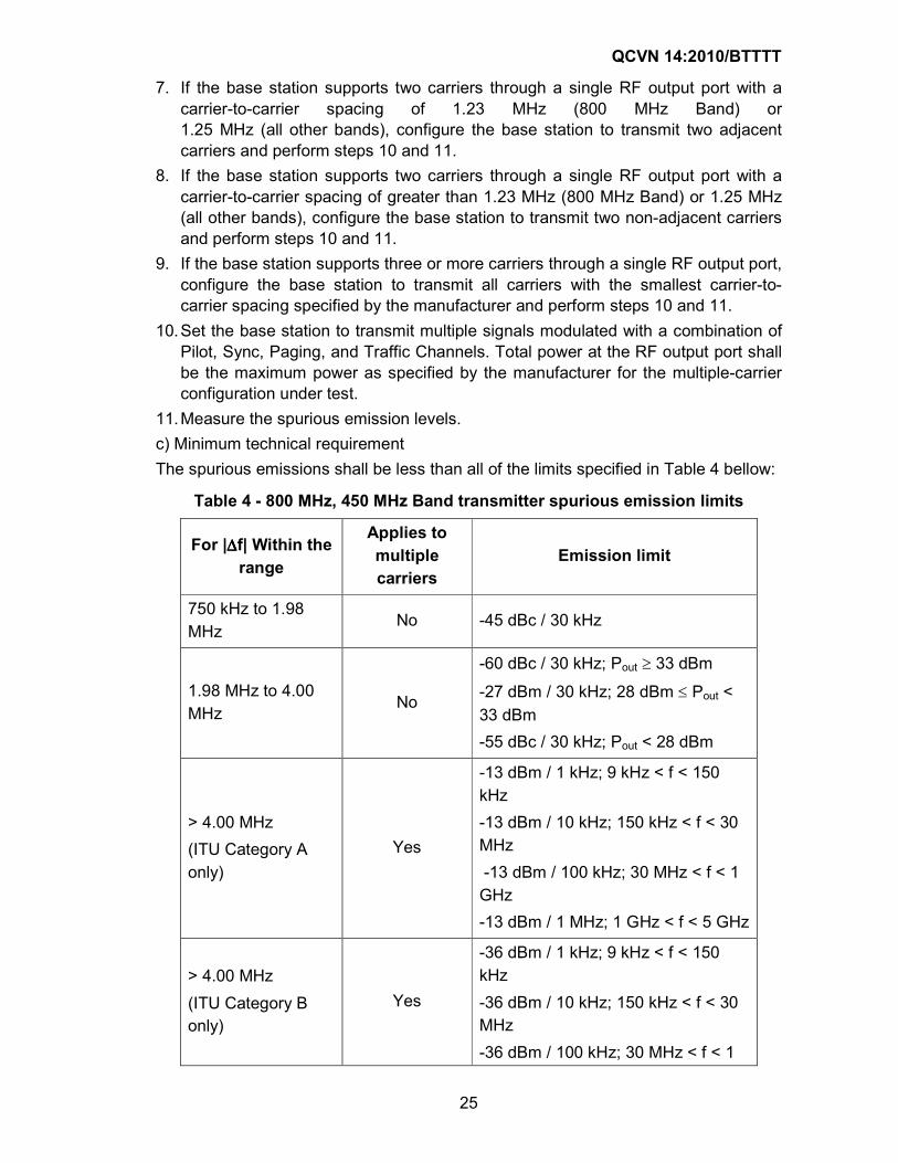
Radiated Spurious Emissions shall not exceed values listed in the following table.
QCVN 14:2010/BTTTT
28
Table 7- Attenuation values and absolute mean power levels used to calculate maximum permitted spurious emission power levels for use with radio
equipment
Frequency band containing the assignment (lower limit exclusive, upper limit inclusive)
For any spurious component, the attenuation (mean power within the necessary bandwidth relative to the mean power of the spurious component concerned) shall be at least that specified below and the absolute mean power levels given shall not be exceeded
235 MHz to 960 MHz
Mean power above 25 W
Mean power 25 W or less
60 dB
20 mW
40 dB
25 µW
960 MHz to 17.7 GHz
Mean power above 10 W
Mean power 10 W or less
50 dB
100 mW
100 µW
2.2.4.3. Inter-Base Station Transmitter Intermodulation
a) Definition
Inter-base station transmitter intermodulation occurs when an external signal source
is introduced to the antenna connector of the base station. This test verifies that
conducted spurious emissions are still met with the presence of the interfering
source.
b) Method of Measurement
1. Connect a spectrum analyzer (or other suitable test equipment) and the external
base station to the base station RF output port, using attenuators or directional
couplers if necessary as shown in Figure 8.
2. For each band that the base station supports, configure the base station to
operate in that band and perform steps 3 through 6.
3. Set the base station under test to transmit a signal modulated with a combination
of Pilot, Sync, Paging, and Traffic Channels. Total power at the RF output port
shall be the maximum power as specified by the manufacturer.
4. Set the second base station to transmit a signal modulated with a combination of
Pilot, Sync, Paging, and Traffic Channels with a total power that is 30 dB less
than the power of the other base station with an offset of 1.25 MHz between the
center of the CDMA center frequencies.
5. Measure the power level at the carrier frequency.
6. Measure the spurious emission level at the image of the base station transmitter
and the interference source. The image is centered at a frequency of 2 times the
center frequency of the base station under test minus the center frequency of the
QCVN 14:2010/BTTTT
29
second base station. The bandwidth of the image is the same as the bandwidth of
the RC in effect.
c) Minimum technical requirement
The base station shall meet the conducted spurious emission requirements in 2.2.4.1
that apply to the image.
2.2.4.4. Occupied Bandwidth
This test applies to 2 GHz Band only.
a) Definition
The occupied bandwidth is define as the frequency range, whereby the power of
emissions averaged over the frequency above and under the edge frequency are
0.5% each of the total radiation power of a modulated carrier.
b) Method of Measurement
1. Connect the spectrum analyzer (or other suitable test equipment) to the base
station RF output port using an attenuator.
2. Set the base station to transmit a single modulated with a combination of Pilot,
Syns, Paging, and Traffic Channels. Total power at the RF output port shall be the
normal power as specified by the manufacturer.
3. Set the resolution bandwidth of the spectrum analyzer to 30 kHz. The value of the
occupied bandwidth is calculated by an external or internal computer by summing
all samples stored as "total power".
c) Minimum technical requirement
The occupied bandwidth shall not exceed 1.48 MHz.
2.3. CDMA general requirements
2.3.1. Temperature and Power Supply Voltage
a) Definition
The temperature and voltage ranges denote the ranges of ambient temperature and
power supply input voltages over which the base station will operate and meet the
requirements of this Standard. The ambient temperature is the average temperature
of the air surrounding the base station equipment. The power supply voltage is the
voltage applied at the input terminals of the base station equipment. The
manufacturer is to specify the temperature range and the power supply voltage over
which the equipment is to operate.
b) Method of Measurement
The base station equipment shall be installed in its normal configuration (i.e., in its
normal cabinet or rack mounting arrangement with all normally supplied covers
installed) and placed in a temperature chamber. Optionally, the equipment containing
the frequency determining element(s) may be placed in the temperature chamber if
QCVN 14:2010/BTTTT
30
the frequency stability is to be maintained over a different temperature from that
specified for the rest of the base station equipment.
The temperature chamber shall be stabilized at the manufacturer's highest specified
operating temperature and then shall be operated in accordance with the standard
duty cycle test conditions specified in Section 6, and over the power supply input
voltage range specified by the manufacturer. With the base station equipment
operating, the temperature is to be maintained at the specified test temperature
without forced circulation of air from the temperature chamber being directly applied
to the base station equipment.
During the entire duty cycle, the transmitter frequency accuracy, timing reference,
output power, and waveform quality shall be measured as specified in Section 4.
Turn the base station equipment off, stabilize the equipment in the chamber at room
temperature, and repeat the above measurements after a 15-minute standby warm
up period.
Turn the base station equipment off, stabilize the equipment in the chamber at the
coldest operating temperature specified by the manufacturer, and repeat the above
measurements above after a 15-minute standby warm up period.
For transmitter frequency stability measurements, the above procedure shall be
repeated every 100C over the operating temperature range specified by the
manufacturer. The equipment shall be allowed to stabilize at each step before a
frequency measurement is made.
c) Minimum technical requirement
Over the ambient temperature and power supply ranges specified by the
manufacturer, the operation of the base station equipment shall conform to the limits
shown in Table 7.
Table 7- Environmental test limits
Parameter Limit Reference
Frequency Tolerance ±0.05 ppm 4.1.2
Time Reference ±10 µs 4.2.1.1
Pilot Waveform Quality ρ > 0.912 4.2.2
RF Power Output Variation +2 dBm, −4 dB 4.3.1
2.3.2. High Humidity
a) Definition
The term "high humidity" denotes the relative humidity at which the base station will
operate with no more than a specified amount of degradation in performance.
b) Method of Measurement
The base station equipment, after having been adjusted for normal operation under
standard test conditions, shall be placed, inoperative, in a humidity chamber with the
humidity maintained at 0.024 gm H2O/gm Dry Air at 500C (40% relative humidity) for
QCVN 14:2010/BTTTT
31
a period of not less than eight hours. While in the chamber and at the end of this
period, the base station transmitting equipment shall be tested for frequency
accuracy, timing reference, output power, and waveform quality. No readjustment of
the base station equipment shall be allowed during this test.
c) Minimum technical requirement
Under the above humidity conditions, the operation of the base station equipment
shall conform to the limits specified in Table 7.
2.3.3. AC Power Line Conducted Emissions
a) Definition
AC power line conducted emissions tests shall be performed on all equipment that
directly connects to the public utility power line. For equipment that receives power
from a device that is directly connected to the public utility power line (such as a DC
power supply), the conducted emissions tests shall be performed on the power
supply device, with the equipment under test connected, to insure that the supply
continues to meet the current emissions standards. AC power line conducted
emissions tests are not required for equipment that contains an internal power source
or battery supply with no means for connection to the public utility power line.
b) Method of Measurement
The conducted measurement procedures described in 2.2.4.1 shall be used for
measuring conducted spurious emissions.
c) Minimum technical requirement
The radio frequency voltage, as measured in 2.3.3.2, shall not exceed 1 mV for
frequencies between 450 and 1705 kHz and shall not exceed 3 mV for frequencies
between 1.705 and 30 MHz.
2.4. Test Modes
The Forward Traffic Channel and Reverse Traffic Channel are verified by invoking
Fundamental Channel test modes, Dedicated Control Channel test modes,
Supplemental Channel test modes, and Supplemental Code Channel test modes.
Table 8 lists the nine test modes and the mapping to radio configurations.
Table 8 - Test modes
Test mode
Forward Traffic Channel Radio Configuration
Reverse Traffic Channel Radio Configuration
1 1 1
2 2 2
3 3 3
4 4 3
5 5 4
QCVN 14:2010/BTTTT
32
6 6 5
7 7 5
8 8 6
9 9 6
Fundamental Channel Test Mode 1 is entered by setting up a call using the
Loopback Service Option (Service Option 2 or 55) or the Markov Service Option
(Service Option 54). Supplemental Code Channel Test Mode 1 is entered by setting
up a call using the Loopback Service Option (Service Option 30).
Fundamental Channel Test Mode 2 is entered by setting up a call using the
Loopback Service Option (Service Option 9 or 55) or the Markov Service Option
(Service Option 54). Supplemental Code Channel Test Mode 2 is entered by setting
up a call using the Loopback Service Option (Service Option 31).
Fundamental Channel Test Modes 3 through 9 are entered by setting up a call using
the Loopback Service Option (Service Option 55), Markov Service Option (Service
Option 54), or Test Data Service Option (Service Option 32).
Dedicated Control Channel Test Modes 3 through 9 and Supplemental Channel Test
Modes 3 through 9 are entered by setting up a call using the Test Data Service
Option (Service Option 32).
2.5. Standard Emissions Measurement Procedures
2.5.1. Radiated Emissions Measurement
2.5.1.1. Standard Radiation Test Site
The test site shall be on level ground that is of uniform electrical characteristics. The
site shall be clear of metallic objects, overhead wires, etc., and shall be as free as
possible from undesired signals, such as ignition noise and other carriers. Reflecting
objects, such as rain gutters and power cables, shall lie outside an ellipse measuring
60 meters on the major axis by 52 meters on the minor axis for a 30-meter site, or an
ellipse measuring 6 meters on the major axis by 5.2 meters on the minor axis for a 3-
meter site. The equipment under test shall be located at one focus of the ellipse and
the measuring antenna at the other focus. If desired, shelters may be provided at the
test site to protect the equipment and personnel. All such construction shall be of
wood, plastic, or other non-metallic material. All power, telephone, and control circuits
to the site shall be buried at least 0.3 meter under ground.
A turntable, essentially flush with the ground, shall be provided that can be remotely
controlled. A platform 1.2 meters high shall be provided on this turntable to hold the
equipment under test. Any power and control cables that are used for this equipment
should extend down to the turntable, and any excess cabling should be coiled on the
turntable.
If the equipment to be tested is mounted in racks and is not easily removed for
testing on the above platform, then the manufacturer may elect to test the equipment
QCVN 14:2010/BTTTT
33
when it is mounted in its rack (or racks). In this case, the rack (or racks) may be
placed directly on the turntable.
If a transmitter with an external antenna is being tested, then the RF output of this
transmitter shall be terminated in a non-radiating load that is placed on the turntable.
A non-radiating load is used in lieu of an antenna to avoid interference with other
radio users. The RF cable to this load should be of minimum length. The transmitter
shall be tuned and adjusted to its rated output value before starting the tests.
2.5.1.2. Search Antenna
For narrow-band dipole adjustable search antennas, the dipole length shall be
adjusted for each measurement frequency. This length may be determined from a
calibration ruler that is normally supplied with the equipment.
The search antenna shall be mounted on a movable non-metallic horizontal boom
that can be raised or lowered on a wooden or other non-metallic pole. The cable
connected to the search antenna shall be at a right angle to the antenna. The cable
shall be dressed at least 3 meters, either through or along the horizontal boom, in a
direction away from the equipment being measured. The search antenna cable may
then be dropped from the end of the horizontal boom to ground level for connection
to the field-strength measuring equipment.
The search antenna shall be capable of being rotated 90 degrees on the end of the
horizontal boom to allow measurement of both vertically and horizontally polarized
signals. When the antenna length of a vertically mounted antenna does not permit
the horizontal boom to be lowered to its minimum specified search range, adjust the
minimum height of the boom for 0.3 meter clearance between the end of the antenna
and the ground.
2.5.1.3. Field-Strength Measurement
A field-strength meter shall be connected to a search antenna. The field-strength
meter shall have sufficient sensitivity and selectivity to measure signals over the
required frequency ranges at levels at least 10 dB below the levels specified in any
document, standard, or specification that references this measurement procedure.
The calibration of the measurement instruments (field-strength meter, antennas, etc.)
shall be checked frequently to ensure that their accuracy is in accordance with the
current standards. Such calibration checks shall be performed at least once per year.
2.5.1.4. Frequency Range of Measurements
When measuring radiated signals from transmitting equipment, the measurements
shall be made from the lowest radio frequency (but no lower than
25 MHz) generated in the equipment to the tenth harmonic of the carrier, except for
that region close to the carrier equal to ±250% of the authorized bandwidth.
When measuring radiated signals from receiving equipment, the measurements shall
be made from 25 MHz to at least 6 GHz.
2.5.1.5. Test Ranges
a) 30-Meter Test Range
QCVN 14:2010/BTTTT
34
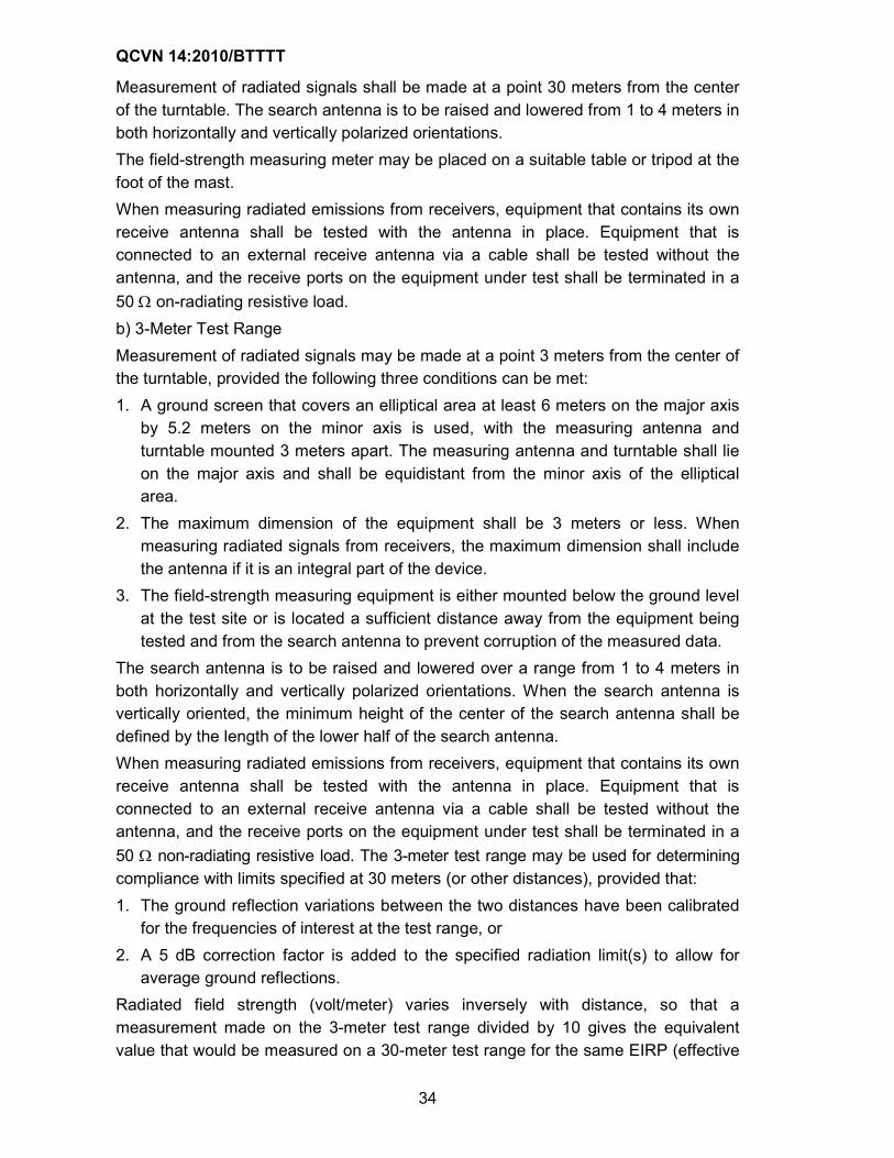
Measurement of radiated signals shall be made at a point 30 meters from the center
of the turntable. The search antenna is to be raised and lowered from 1 to 4 meters in
both horizontally and vertically polarized orientations.
The field-strength measuring meter may be placed on a suitable table or tripod at the
foot of the mast.
When measuring radiated emissions from receivers, equipment that contains its own
receive antenna shall be tested with the antenna in place. Equipment that is
connected to an external receive antenna via a cable shall be tested without the
antenna, and the receive ports on the equipment under test shall be terminated in a
50 Ω on-radiating resistive load.
b) 3-Meter Test Range
Measurement of radiated signals may be made at a point 3 meters from the center of
the turntable, provided the following three conditions can be met:
1. A ground screen that covers an elliptical area at least 6 meters on the major axis
by 5.2 meters on the minor axis is used, with the measuring antenna and
turntable mounted 3 meters apart. The measuring antenna and turntable shall lie
on the major axis and shall be equidistant from the minor axis of the elliptical
area.
2. The maximum dimension of the equipment shall be 3 meters or less. When
measuring radiated signals from receivers, the maximum dimension shall include
the antenna if it is an integral part of the device.
3. The field-strength measuring equipment is either mounted below the ground level
at the test site or is located a sufficient distance away from the equipment being
tested and from the search antenna to prevent corruption of the measured data.
The search antenna is to be raised and lowered over a range from 1 to 4 meters in
both horizontally and vertically polarized orientations. When the search antenna is
vertically oriented, the minimum height of the center of the search antenna shall be
defined by the length of the lower half of the search antenna.
When measuring radiated emissions from receivers, equipment that contains its own
receive antenna shall be tested with the antenna in place. Equipment that is
connected to an external receive antenna via a cable shall be tested without the
antenna, and the receive ports on the equipment under test shall be terminated in a
50 Ω non-radiating resistive load. The 3-meter test range may be used for determining
compliance with limits specified at 30 meters (or other distances), provided that:
1. The ground reflection variations between the two distances have been calibrated
for the frequencies of interest at the test range, or
2. A 5 dB correction factor is added to the specified radiation limit(s) to allow for
average ground reflections.
Radiated field strength (volt/meter) varies inversely with distance, so that a
measurement made on the 3-meter test range divided by 10 gives the equivalent
value that would be measured on a 30-meter test range for the same EIRP (effective
QCVN 14:2010/BTTTT
35
isotropic radiated power). The 30-meter field strength in volt/meter can be calculated
from the EIRP by using the following formula:
µV/m @ 30 meters = 5773.5 × 10EIRP(dBm)/20
2.5.1.6. Radiated Signal Measurement Procedures
Radiated signals having significant levels shall be measured on the 30-meter or 3-
meter test range by using the following procedure:
1. For each observed radiated signal, raise and lower the search antenna to obtain a
maximum reading on the field-strength meter with the antenna horizontally
polarized. Then rotate the turntable to maximize the reading. Repeat this
procedure of raising and lowering the antenna and rotating the turntable until the
highest possible signal has been obtained. Record this maximum reading.
2. Repeat step 1 for each observed radiated signal with the antenna vertically
polarized.
3. Remove the equipment being tested and replace it with a half-wave antenna. The
center of the half-wave antenna should be at the same approximate location as
the center of the equipment being tested.
4. Feed the half-wave antenna replacing the equipment under test with a signal
generator connected to the antenna by means of a non-radiating cable. With the
antennas at both ends horizontally polarized and with the signal generator tuned
to the observed radiated signal, raise and lower the search antenna to obtain a
maximum reading on the field-strength measuring meter. Adjust the level of the
signal generator output until the previously recorded maximum reading for this set
of conditions is obtained. Record the signal generator power output.
5. Repeat step 4 above with both antennas vertically polarized.
6. Calculate the power into a reference ideal isotropic antenna by:
a) First reducing the readings obtained in steps 4 and 5 above by the power loss
in the cable between the generator and the source antenna, and
b) Then correcting for the gain of the source antenna used relative to an ideal
isotropic antenna. The reading thus obtained is the equivalent effective
isotropic radiated power (EIRP) level for the spurious signal being measured.
7. Repeat steps 1 through 6 above for all observed signals from the equipment
being tested.
2.5.2. AC Power Line Conducted Emissions Measurement
2.5.2.1. Standard AC Power Line Conducted Emissions Test Site
The test site shall be on level ground that is covered with an earth-grounded,
conductive surface that is at least 2 meters by 2 meters in size. The ground plane
shall extend at least 0.5 meter beyond the foot print of the equipment under test.
A vertical conducting plane is optional for a standard (open area) test site and is only
required for measurements made on table-top devices. If a vertical conducting plane
is used, it shall be at least 2 meters by 2 meters in size and shall be electrically
QCVN 14:2010/BTTTT
36
attached to the conductive ground plane at maximum intervals of one meter along its
entire length.
2.5.2.2. Line Impedance Stabilization Network (LISN) Unit
A Line Impedance Stabilization Network (LISN) shall be used for equipment that is
tested on a standard test site and connects directly to the public utility power line, or
receives power from a device that connects to the public utility power line. The LISN
shall be placed on top of or directly underneath the conductive ground plane and
shall be electrically grounded to it. Power line filters between the power source and
LISN may be used to reduce the ambient noise level on the public utility line.
2.5.2.3. Standard Test Site Measurements
a) Floor Standing Equipment
Floor standing equipment shall be placed directly on the conductive ground plane. If
a vertical conducting plane is used, the equipment under test shall be located 40 cm
from the vertical conducting surface. All other conductive objects (including the LISN)
shall be located at least 80 cm from any surface on the equipment under test.
b) Table Top Mounted Equipment
Table top equipment shall be placed on top of a non-conductive platform, with
nominal long dimension of 1.5 meters, and located 80 cm above the horizontal
conducting ground plane. The equipment under test shall be placed 40 cm from the
vertical conductive surface, with all other conductive objects located at least 80 cm
from any surface on the equipment under test.
c) Measurement Procedure
A radio noise meter employing a quasi-peak detector shall be used to test for radio
noise between each current carrying conductor and the ground conductor. Each
current carrying conductor shall be tested individually with all unused connections on
the LISN terminated in a 50 Ω resistive load. The ground (safety) conductor on the
equipment under test shall be individually connected to the power source through the
LISN. Any adapters used between the LISN power socket and the equipment under
test shall be no more than 20 cm long and shall contain only one input and only one
output.
The equipment under test shall be tested in various modes of operation with
numerous cable orientations. The emissions level shall be recorded for the mode of
operation and cable orientation that maximizes the radio noise level. This maximizing
technique shall be repeated for measurements on each current carrying conductor.
d) Frequency Range of Measurements
When measuring AC power line conducted emissions, the measurements shall be
made at frequencies between 450 kHz and 30 MHz.
2.5.2.4. End User or Manufacturing Plant Test Sites
For equipment that cannot be tested at a standard (open area) test site, an AC power
line conducted emissions test may be performed at the end users location or at the
manufacturing plant.
QCVN 14:2010/BTTTT
37
2.6. CDMA standard test conditions
2.6.1. Standard Equipment
2.6.1.1. Basic Equipment
The equipment shall be assembled and any necessary adjustments shall be made in
accordance with the manufacturer's instructions for the mode of operation required.
When alternative modes are available, the equipment shall be assembled and
adjusted in accordance with the relevant instructions. A complete series of
measurements shall be made for each mode of operation.
2.6.1.2. Associated Equipment
The base station equipment may include associated equipment during tests if the
associated equipment is normally used in the operation of the equipment under test.
This would include power supplies, cabinets, antenna couplers, and receiver multi-
couplers.
2.6.2. Standard Environmental Test Conditions
Measurements under standard atmospheric conditions shall be carried out under any
combination of the following conditions:
• Temperature: +150C to +350C;
• Relative Humidity: 45% to 75%;
• Air Pressure: 86,000 to 106,000 Pa (860 to 1060 mbar).
If desired, the results of the measurements can be corrected by calculation to the
standard reference temperature of 250C and the standard reference air pressure of
101,300 Pa (1013 mbar).
2.6.3. Standard Conditions for the Primary Power Supply
2.6.3.1. General
The standard test voltages shall be those specified by the manufacturer as minimum,
normal, and maximum operating values. The voltage shall not deviate from the stated
values by more than ±2% during a series of measurements carried out as part of one
test on the same equipment.
2.6.3.2. Standard DC Test Voltage from Accumulator Batteries
The standard (or nominal) DC test voltage battery specified by the manufacturer shall be
equal to the standard test voltage of the type of accumulator to be used multiplied by
the number of cells minus an average DC power cable loss value that the
manufacturer determines as being typical (or applicable) for a given installation.
Since accumulator batteries may or may not be under charge and, in fact, may be in
a state of discharge when the equipment is being operated, the manufacturer shall
also test the equipment at anticipated voltage extremes above and below the
standard voltage. The test voltages shall not deviate from the stated values by more
than ±2% (nominal float voltage) during a series of measurements carried out as part
of one test on the same equipment.
2.6.3.3. Standard AC Voltage and Frequency
QCVN 14:2010/BTTTT
38
For equipment that operates from the AC mains, the standard AC test voltage shall
be equal to the nominal voltage specified by the manufacturer. If the equipment is
provided with different input taps, the one designated nominal shall be used. The
standard test frequency and the test voltage shall not deviate from their nominal
values by more than ±2%.
The equipment shall operate without degradation with input voltage variations of up
to ±10% and shall maintain its specified transmitter frequency stability for input
voltage variations of up to ±15%. The frequency range over which the equipment is to
operate shall be specified by the manufacturer.
2.6.4. Standard Test Equipment
2.6.4.1 Channel Simulator
The channel simulator shall support the following channel model parameters:
• All paths are independently faded.
• The fading is Rayleigh. The probability distribution function of power, F(P), is:
≤
>−=
−
0P,0
0P,e1)P(F
aveP/P
where P is the signal power level and Pave is the mean power level.
• The level crossing rate, L(P) is:
≤
>π=
−
0P,0
0P,e.f.PP2)P(L
avePPdave
where fd is the Doppler frequency offset associated with the simulated vehicle speed
given by:
,fc
vf cd
=
fc is the carrier frequency, v is the vehicle speed, and c is the speed of light in a
vacuum.
• The power spectral density, S(f), is:
+≤≤−
−−=
otherwise,0
fffff,
f
ff1
1
)f(S
dcdc2
d
c
• The autocorrelation coefficient of the unwrapped phase, ρ(t), is:
( )[ ] ( )[ ] ( )[ ]∑∞
=
−− π
π−
π
π+π
π=ρ
1n2
n2
d02
2
d01
d01
n
t.f2J
4
3t.f2Jsin
2
16t.f2Jsin
2
3)t(
where J0( ) is a zero-order Bessel function of the first kind.
This autocorrelation coefficient is shown in Figure 1.
QCVN 14:2010/BTTTT
39
Figure 1 - Autocorrelation Coefficient of the Phase
The following standard conditions and tolerances on the channel model parameters
shall be supported by the channel simulator:
• Vehicle Speed, v, as shown in Table 9.
The tolerance on Doppler shall be ±5%.
• Power distribution function, F(P)
1. The tolerance shall be within ±1 dB of calculated, for power levels from
10 dB above to 20 dB below the mean power level.
2. The tolerance shall be within ±5 dB of calculated, for power levels from
20 dB below to 30 dB below the mean power level.
• Level crossing rate, L(P)
The tolerance shall be within ±10% of calculated, for power levels from
3 dB above to 30 dB below the mean power level.
• Measured power spectral density, S(f), around the carrier, fc:
1. At frequency offsets |f - fc| = fd, the maximum power spectral density S(f)
shall;
exceed S(fc) by at least 6 dB.
2. For frequency offsets |f - fc| > 2fd, the maximum power spectral density
S(f) shall be less than S(fc) by at least 30 dB.
• Simulated Doppler frequency, fd, shall be computed from the measured S(f) as:
( )21
2
cd
df)f(S
df)f(Sff2f
−=
∫∫
1.2
1.0
0.8
0.6
0.4
0.2
0
-0.2
0.5 1 1.5 2.52 3
Lag t in units of 1/Doppler frequency
QCVN 14:2010/BTTTT
40
• Measured autocorrelation coefficient of the unwrapped phase, ρ(t)
1. At a lag of 0.05/fd shall be 0.8 ± 0.1.
2. At a lag of 0.15/fd shall be 0.5 ± 0.1.
Table 9 - Standard Channel Simulator Configurations
Channel Simulator Configuration 1 2 3 4
Vehicle Speed [km/h] 3 8 30 100
Number of Paths 1 2 1 3
Path 2 Power (Relative to Path 1)
[dB] N/A 0 N/A 0
Path 3 Power (Relative to Path 1)
[dB] N/A N/A N/A -3
Delay from Path 1 to Input [µs] 0 0 0 0
Delay from Path 2 to Input [µs] N/A 2.0 N/A 2.0
Delay from Path 3 to Input [µs] N/A N/A N/A 14.5
2.6.4.2. Waveform Quality Measurement Equipment
a) Rho Meter
Equipment capable of performing waveform cross-correlation shall be used for the
measurement of forward link frequency tolerance, pilot time tolerance, and waveform
compatibility.
Various equipment implementations are possible. The equipment used shall provide
results equivalent to those produced by equipment that use the following algorithms:
The ideal transmitter signal is given as
tji
i
ce)t(R)t(s ω−∑=
where
ωc is the nominal carrier frequency of the signal
Re[s] denotes the real part of the complex number s
Ri(t) is the complex envelope of the ideal ith code channel, given as:
( ) ( ) ( ) ( )
φ−+φ−= ∑ ∑
k kk.ick,icii sinkTtgjcoskTtga)t(R
where
ai is the amplitude of the ith code channel,
g(t) is the unit impulse response of the cascaded transmit filter and phase equalizer
described in 3.1.3.1.14 of [3],
φi,k is the phase of the kth chip for the ith code channel, occurring at discrete time tk =
kTc.
Modulation accuracy is the ability of the transmitter to generate the ideal signal s(t).
QCVN 14:2010/BTTTT
41
The actual transmitter signal is given by:
( )[ ] ( )[ ]iic t)(jiiii
i
e)t(EtRb)t(xθ+τ+ω∆+ω−+τ+= ∑
where
bi is the amplitude of the actual signal relative to the ideal signal for the ith code
channel,
τi is the time offset of the actual signal relative to the ideal signal for the ith code
channel,
∆ω is the radian frequency offset of the signal,
θi is the phase offset of the actual signal relative to the ideal signal for the ith code
channel, and Ei(t) is the complex envelope of the error (deviation from ideal) of the
actual transmit signal for the ith code channel.
Estimates of the radian frequency offset ∆ω = 2π∆f and the time offset τ0, of the pilot
shall be obtained to the accuracy specified below in Table 10. These estimates
0ˆ,ˆ τω∆ and 0θ , shall be used to compensate x(t) by introducing a time correction and
a complex multiplicative factor to produce y(t), a compensated version of x(t):
( ) ( )[ ]0cˆtˆj
0 eˆtx)t(y θ+ϖ∆+ωτ−=
The radian frequency offset ϖ∆ ˆ is converted to hertz frequency offset f∆ by:
πϖ∆
=∆2
ˆf
The compensated signal, y(t), shall be passed through a complementary filter to
remove the inter-symbol interference (ISI) introduced by the transmit filter and by the
transmit phase equalizer to yield an output z(t). The overall impulse response of the
filter chain resulting from cascading the complementary filter with the ideal transmit
filter and equalizer shall approximately satisfy Nyquist criterion for zero ISI. The
Nyquist criterion shall be approximated by filter null levels at least 50 dB below the
on-time response at the appropriate sample times. The noise bandwidth of the
complementary low pass filter shall be less than 625 kHz.
The idealized output of the complementary filter is:
)t(R~
)t(ri
i∑=
where
( ) ( )[ ]k,ik,iiki sinjcosa)t(R~
φ+φ=
Modulation accuracy is measured by determining the fraction of power at the
complementary filter output, z(t), that correlates with )(~0 ktR , the compensated pilot
signal. The filter output is sampled at the ideal decision points when the transmitter is
modulated only by the Pilot Channel (the 0th code channel). The waveform quality
factor (ρ) is defined as:
QCVN 14:2010/BTTTT
42
,
ZR~
RZ
M
1k
M
1k
2
k
2
k,0
2M
1k
*
k,0k
=ρ
∑ ∑
∑
= =
=
where
Zk = z[k] is the kth sample of the output of the complementary filter, and
[ ]kR~
R~
0k,0 = is the corresponding sample of the ideal output of the complementary
filter for the Pilot Channel.
Modulation accuracy shall be measured by using the k complex-valued samples,
z(tk), over a time interval M, in chips, of at least one power control group and an
integer multiple of 512 chips.
The accuracy of the waveform quality measurement equipment shall be as shown in
Table 10.
Table 10 - Accuracy of waveform Quality Measurement Equipment
Parameter Symbol Accuracy Requirement
Waveform Quality ρ ±5 × 10⁻⁴ from 0.09 to
1.0
Frequency Offset (exclusive of
test equipment time base
errors)
∆f ±10 Hz
Pilot Time Alignment Offset τ0 ± 135 ns
b) Code Domain Measurement Equipment
See a) for definition of signal parameters. Code domain measurement equipment
estimates:
1. Walsh code domain power coefficients ρ0, ρ1, ρ2,..., ρL-1 (see below for definition).
2. Walsh code domain time offsets relative to pilot ∆τi, where:
∆τi = τi - τ0
3. Walsh code domain phase offsets relative to pilot ∆θi, where:
∆θi = θi - θ0
4. Frequency offset:
∆f = fc- f0
Code domain power is defined as the fraction of power in z(tk) that correlates with
each Ri(tk) when the transmitter is modulated according to a known code symbol
sequence. The actual signal is compensated in frequency offset ∆ϖ, pilot time
alignment offset τ0, and pilot phase θ0.
Code domain power coefficients ρi are defined as:
QCVN 14:2010/BTTTT
43
=ρ
∑∑∑
∑ ∑
= ==
= =
N
1j
64
1k
2
k,j
64
1k
2
k,j,i
2N
1j
64
1k
*
k,j,ik,j
i
ZR
RZ
i = 0, 1, 2,..., L-1
where Zk is defined in 6.4.2.1, is the maximum Walsh function length, [ ]kR~
R~
ik,j,i =
is the kth sample of the ideal output of the complementary filter for the ith code
channel, and N is the measurement interval in units of the longest Walsh length,
which shall be at least one power control group in length and an integer multiple of
512 chips.
The code domain time offsets τi and phase offsets θi shall be determined by creating
the reference signal:
( ) ( )[ ]iikˆˆtˆj
iki
ik eˆtRR θ+τ+ϖ∆−τ+= ∑
and finding the estimates ii a,ˆ,ˆ τϖ∆ and iθ to minimize the sum-square-error:
2N
1kkk
2 RZ∑=
−=ε
where Z k= z(tk) is the output of the complementary filter at the kth sample time.
The accuracy of the code domain measurement equipment shall be as shown in
Table 11 for the nominal Base Station Test Model (refer to 2.6.5.2).
Table 11- Accuracy of Code Domain Measurement Equipment
Parameter Symbol Accuracy
Requirement
Code domain power coefficients ρi
±5 × 10⁻⁴ from 5 × 10⁻⁴
to 1.0
Frequency Offset (exclusive of test
equipment time base errors) ∆f ±10 Hz
Code domain time offset relative to
pilot ∆τi ± 10 ns
Code domain phase offset relative to
pilot ∆θi ± 0.01 radians
2.6.4.3. Mobile Station Simulator
The mobile station simulator shall be compliant with 3GPP2 C.S0002-A-1 and
C.S0011-A. The mobile station simulator shall support Service Option 2, 9, and 55 of
3GPP2 C.S0013-A and Service Option 32 of 3GPP2 C.S0026 and may support
Service Option 54 of 3GPP2 C.S0025.
QCVN 14:2010/BTTTT
44
It shall be possible to disable reverse link closed loop power control in the mobile
station simulator. This includes reverse link closed loop power control commands
sent on the Forward Power Control Subchannel and the Common Power Control
Channel. When closed loop power control is disabled, it shall be possible to set the
mobile station simulator transmit power to any fixed level with a resolution of ±0.1 dB
over the full dynamic range.
The mobile station simulator shall include a power control test program. The program
function is to cycle the transmit power as shown in Figure 4.2.3.2-1. The transitions of
output power shall be aligned with the power control group boundaries as defined in
6.1 of 3GPP2 C.S0002-A-1. It shall also provide a timing reference signal aligned to
the power cycles and it may provide the value of the power control bits received on
the forward link. The duration of the high and low power period shall be at least 5 ms
(4 power control groups).
When testing Radio Configuration 3 through 6 demodulation (2.1.2, 2.1.3 and 2.1.4),
the mobile station simulator shall apply the Nominal Reverse Common Channel
Attribute Gain Table and Reverse Link Nominal Attribute Gain Table values specified
in Section 2.1.2.3.3.1 and 2.1.2.3.3.2 of [3], respectively.
2.6.4.4. AWGN Generator
The AWGN generator shall meet the following minimum performance requirements:
• Minimum Bandwidth: 1.8 MHz for Spreading Rate 1
• Frequency Ranges:
824 MHz to 894 MHz;
411 MHz to 484 MHz;
1920 MHz to 1980 MHz.
• Frequency Resolution: 1 kHz
• Output Accuracy: ±2 dB for outputs ≥ -80 dBm
• Output Settability: 0.1 dB
• Output Range: -20 to -95 dBm
• Gain Flatness: 1.0 dB over the minimum bandwidth.
• The AWGN generators shall be uncorrelated to the ideal transmitter signal and to
each other.
2.6.4.5. CW Generator
• Output Frequency Range: Tunable over applicable range of radio frequencies for
band under test.
• Frequency Accuracy: ± 1 ppm.
• Frequency Resolution: 100 Hz.
• Output Range: -50 dBm to -10 dBm, and off.
• Output Accuracy: ± 1.0 dB.
• Output Resolution: 0.1 dB.
• Output Phase Noise at -20 dBm Power:
QCVN 14:2010/BTTTT
45
-149 dBc/Hz at a frequency of 1 GHz as measured at a 285 kHz offset
(800 and 450 MHz bands)
-144 dBc/Hz at a frequency of 2 GHz as measured at a 655 kHz offset
(2 GHz band).
2.6.4.6. Spectrum Analyzer
The spectrum analyzer shall provide the following functionality:
• General purpose frequency domain measurements.
• Integrated channel power measurements (power spectral density in 1.23 MHz)
The spectrum analyzer shall meet the following minimum performance requirements:
• Frequency Range: Tunable over applicable range of radio frequencies.
• Frequency Resolution: 1 kHz.
• Frequency Accuracy: ± 0.2 ppm.
• Displayed Dynamic Range: 70 dB.
• Display Log Scale Fidelity: ±1 dB over the above displayed dynamic range.
• Amplitude Measurement Range for signals from 10 MHz to either 2.6 GHz for
800, 450 MHz bands or 6 GHz for 2 GHz band:
Power measured in 30 kHz Resolution Bandwidth: -90 to +20 dBm.
Integrated 1.23 MHz Channel Power: -70 to +47 dBm.
Note: The Standard RF Output Load described in 6.4.8 may be used to meet the high power end of these
measurements.
• Absolute Amplitude Accuracy in the CDMA transmit and receive bands for
integrated 1.23 MHz channel power measurements:
±1 dB over the range of -40 dBm to +20 dBm
±1.3 dB over the range of -70 dBm to +20 dBm
• Relative Flatness: ±1.5 dB over frequency range 10 MHz to either 2.6 GHz
• Resolution Bandwidth Filter: Synchronously tuned or Gaussian (at least
3 poles) with 3 dB bandwidth selections of 1 MHz, 300 kHz, 100 kHz, and 30 kHz.
• Post Detection Video Filters: Selectable in decade steps from 100 Hz to at least 1
MHz.
• Detection Modes: Selectable to be either Peak or Sample.
• RF Input Impedance: Nominal 50 ohm
2.6.4.7. Average Power Meter
The power meter shall provide the following functionality:
• Average power measurements.
• True RMS detection for both sinusoidal and non-sinusoidal signals
• Absolute power in linear (watt) and logarithmic (dBm) units.
• Relative (offset) power in dB and % units.
• Automatic calibration and zeroing.
QCVN 14:2010/BTTTT
46
• Averaging of multiple readings.
The power meter shall meet the following minimum performance requirements:
• Frequency Range: 10 MHz to either 1 GHz
• Power Range: -70 dBm (100 pW) to +47 dBm (50 W)
Different sensors may be required to optimally provide this power range. The RF
output load described in 6.4.8 may be used to meet the high power end of these
measurements.
• Absolute and Relative Power Accuracy: ±0.2 dB (5%)
Excludes sensor and source mismatch (VSWR) errors, zeroing errors (significant at
bottom end of sensor range), and power linearity errors (significant at top end of
sensor range).
• Power Measurement Resolution: Selectable 0.1 and 0.01 dB.
• Sensor VSWR: 1.15:1
2.6.4.8. RF Output Load
The base station transmitter output shall be connected through suitable means to the
measurement equipment or mobile station simulator. The means shall be non-
radiating and capable of continuously dissipating the full transmitter output power.
The VSWR seen by the transmitter over the 1.23 MHz band centered at the nominal
transmit frequency under test shall be less than 1.1:1.
The base station transmitter signal may be terminated and sampled using a dummy
load, attenuator, directional coupler, or combination thereof.
2.6.5. Test Setups
2.6.5.1. Functional System Setups
Figure 2 - Functional Setup for Base Statione Sensivity Tests
Base station
under test
Atten.
Power
meter
Load
Tx
Rx (A)
Rx (B)
Tx
AWGN
generator
Rx
Mobile station
simulator
Power
meter
Atten.
Atten.
AWGN
generator
QCVN 14:2010/BTTTT
47
Figure 3 - Functional Setup for Base Station Desensitization Tests
Figure 4 - Functional Setup for Base Station Intermodulation Spurious Response Tests
Figure 5 - Functional Setup for Waveform Quality Test
Tx
Rx (A)
Rx (B)
Tx
RxPower
meter
Base station
under test
Power
meter
Atten.
CW
generator
Load
Atten.
Atten.
Atten.
Atten.
Mobile station
simulator
Tx
Rx (A)
Rx (B)
Tx
Rx
Base station
under test
Power
meter
Atten.
Load
CW generator
Mobile station
simulatorPower
meter
CW generator
Atten.
Atten.
Atten.
Atten.
Tx
Rx (A)
Rx (B)
Waveform
analyzer
Base station
under test
Atten.
Load
QCVN 14:2010/BTTTT
48
Figure 6 - Functional Setup for Code Domain Power Test for Non-transmit Diversity Configuration
Figure 7- Functional Setup for Code Domain Power Test for Transmit Diversity Configuration
Figure 8 - Functional Setup for Inter-Base Station Intermodulation Tests
Tx
Rx (A)
Rx (B)
Base station
under test
Atten.
Load
Code domain
power
analyzer
Tx (A)
Rx (A)
Rx (B)
Code domain
power
analyzer
Tx (B)
Base station
under test Load
Atten.
Tx
Rx (A)
Rx (B)
Spectrum
analyzerExternal
base station
Base station
under test
Load
Atten.
QCVN 14:2010/BTTTT
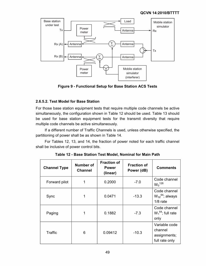
49
Figure 9 - Functional Setup for Base Station ACS Tests
2.6.5.2. Test Model for Base Station
For those base station equipment tests that require multiple code channels be active
simultaneously, the configuration shown in Table 12 should be used. Table 13 should
be used for base station equipment tests for the transmit diversity that require
multiple code channels be active simultaneously.
If a different number of Traffic Channels is used, unless otherwise specified, the
partitioning of power shall be as shown in Table 14.
For Tables 12, 13, and 14, the fraction of power noted for each traffic channel
shall be inclusive of power control bits.
Table 12 - Base Station Test Model, Nominal for Main Path
Channel Type Number of Channel
Fraction of Power (linear)
Fraction of Power (dB)
Comments
Forward pilot 1 0.2000 -7.0 Code channel
W0128
Sync 1 0.0471 -13.3
Code channel
W3264; always
1/8 rate
Paging 1 0.1882 -7.3
Code channel
W164; full rate
only
Traffic 6 0.09412 -10.3
Variable code
channel
assignments;
full rate only
Tx
Rx (A)
Rx (B)
Power
meter
Tx
Rx
Mobile station
simulator
Base station
under test
Load
Antenna
Antenna
AntennaAntenna
Antenna
Power
meter
Mobile station
simulator
(interferer)
QCVN 14:2010/BTTTT
50
Table 13 - Base Station Teat Model, Nominal for Transmit Diversity Path
Channel Type Number of Channel
Fraction of Power (linear)
Fraction of Power (dB)
Comments
Transmit
Diversity Pilot 1 0.2000 -7.0
Code
channel
W16128
Traffic 6 0.09412 -10.3
Variable
code
channel
assignments;
full rate only
Table 14 - Base Station Test Model, General
Channel Type Relative Power
Pilot 0.2 of total power (linear)
Sync + Paging +
Traffic
Remainder (0.8) of total power (linear)
Sync 3 dB less than one Fundamental Traffic
Channel; always 1/8 rate
Paging 3 dB greater than one Fundamental Traffic
Channel; full rate only
Traffic Equal power in each Fundamental Traffic
Channel; full rate only
2.6.5.3. General Comments
The following comments apply to all CDMA tests:
1. Unless specified otherwise, test configurations should use the nominal base
station parameter settings specified by the base station manufacturer.
2. Overhead message fields should be those needed for normal operation of the
mobile station and the base station unless stated differently below or in s specific
test.
Special field values of the Enhanced Access Parameters Message
Specific Eb/N0 values have been chosen to allow manufacturers to conduct tests in a
timely manner for the specified confidence levels.
Any reliable statistical procedure may be used to establish the confidence level. The
tests may be either single-sided or two-sided. They also may be either fixed length or
variable length. The procedure shall satisfy the following requirements:
• An established procedure shall be employed. It shall include:
- Specification of minimum and maximum test length.
- Criteria for early termination.
• Objective pass-fail criteria shall be established.
• Steps to be taken to rerun the test in case of a failure shall be specified.
Trial-to-trial correlations of errors, as may occur in frame error measurements in slow
fading scenarios, should be taken into account. In addition to statistical variations in
measurements, systematic errors due to test equipment tolerances and calibration
should be considered in interpretation of results.
An acceptable procedure is as follows. Assume independent Bernoulli trials, where
the outcome of each trial is classified as either “error” or “no error” The specification
error rate limit is λlim and the required confidence level is C.
1. Choose a suitable test length in terms of a maximum number of errors, Kmax. The
exact value is not critical, but must be large enough to ensure that compliant units
pass with very high probability. This probability depends on the design rate ratio
λ/λlim between the design error rate and the specification error rate limit. Values of
Kmax in the range of 30-100 should be suitable based on the margins in this
Standard.
2. Carry out Nmax or more trials under specified test conditions, where
Nmax = lim
max 2
2
)K2,C1(
λ−χ
and x2(P, n) is the inverse x2-distribution corresponding to probability P and n
degrees-of-freedom. Table 15 gives Nmax versus the actual number of errors (K) for
C = 95% and representative λlim. Table 16 gives Nmax versus the actual number of
errors (K) for C = 90% and representative λlim.
3. Compute the empirical error rate
λN = KN/N
and the empirical rate ratio λ/λlim, where KN is the number of errors in the N trials
actually performed.
4. If the rate ratio is less than the confidence limit:
Nmax = )2K2,C1(
K2
N2
N
+−χ
or equivalently:
N > lim
N2
2
)2K2,C1(
λ+−χ
QCVN 14:2010/BTTTT
53
then the unit under test has passed; otherwise the unit has failed.
5. If the unit fails, repeat steps 2-4 twice more. If the unit passes both individual tests
then it passes overall; otherwise the unit has failed. This procedure may be
modified to permit early termination. A test may be performed at every trial, or
after a block of trials. Steps 3 and 4 are modified as follows:
3'. After each trial or block of trials compute the empirical error rate as
λN = KN/N
where KN is the number of errors up to and including the current (Nth) trial, and the
rate ratio λNλlim.
4'. If after the Nth trial the rate ratio is less than the confidence limit
λN/λlim < )2K2,C1(
K2
N2
N
+−χ
or equivalently:
N >
lim
N2
2
)2K2,C1(
λ
+−χ
then the unit under test has passed and the testing stops. If the number of trials
reaches Nmax then the unit has failed and the testing stops.
Table 15 - Trial Count (N) Thresholds for 95% Confidence
K λλλλlim
General 0.5% 1.0% 5.0%
0 599 300 60 3.00/λlim
1 599 300 60 3.00/λlim
2 949 474 95 4.74/λlim
3 1259 630 126 6.30/λlim
4 1551 775 155 7.75/λlim
5 1831 915 183 9.15/λlim
6 2103 1051 210 10.51/λlim
7 2368 1184 237 11.84/λlim
8 2630 1315 263 13.15/λlim
9 2887 1443 289 14.43/λlim
10 3141 1571 314 15.71/λlim
32 8368 4184 837 41.84/λlim
64 15540 7770 1554 77.70/λlim
128 29432 14716 2943 147.16/λlim
256 56575 28287 5657 282.87/λlim
QCVN 14:2010/BTTTT
54
Table 16 - Trial Count (N) Thresholds for 90% confidence
K λλλλlim
General 10.0% 50.0%
0 24 5 N/A
1 24 5 2.30/λlim
2 39 8 3.89/λlim
3 54 11 5.32/λlim
4 67 14 6.63/λlim
5 80 16 8.00/λlim
6 93 19 9.28/λlim
7 106 22 10.53/λlim
8 118 24 11.77/λlim
9 130 26 13.00/λlim
10 143 29 14.21/λlim
32 395 79 39.43/λlim
64 745 149 74.44/λlim
128 1427 286 142.70/λlim
256 2768 554 276.71/λlim
3. MANAGEMENT REGULATIONS
Handsets use CDMA 2000-1x technology must comply with requirements in this technical regulation.
4. RESPONSIBILITY OF ORGANISATIONS/INDIVIDUALS
Organisations/individuals in Vietnam are responsible to comply with this technical regulation and to accept supervision of regulatory authority as existing regulations.
5. IMPLEMENTATION
5.1. Vietnam Telecommunication Authority and local departments of Information and Communications are responsible for guidance and implementation of this technical regulation.
5.2. This Technical regulation replace standard TCN 68-223:2005 “Cellular mobile CDMA 1X base stations-Technical requirements”.
5.3. In cases of having referencing regulations specified in this technical regulation changed, modified or superseded, the new reference versions are applied.