Page 1
QoSMOS D7.3
The research leading to these results was derived from the European Community’s Seventh Framework
Programme (FP7) under Grant Agreement number 248454 (QoSMOS)
FP7-ICT-2009-4/248454
QoSMOS
D7.3
QoSMOS Prototype - version 1
Contractual Date of Delivery to the CEC: 30-June-2012
Actual Date of Delivery to the CEC: 12th July 2012
Editor(s): Dominique Noguet (CEA)
Author(s): Dominique Noguet, Vincent Berg, Xavier Popon, Marc Laugeois (CEA),
Jonathan Duplicy, Martin Zelenak, Deepaknath Tandur (AGILENT), Arturo
Medela, Juan Rico, Martina Fuentevilla (TST), Carlos Ribeiro, Jose
Quaresma (IT), Mengistu Tessema, Mario Schuehler (IIS), Philippe
Delahaye (NTUK)
Work package: WP7
Est. person months: 28
Security: PU
Nature: P
Version: Issue 1
Total number of pages: 36
Abstract:
Deliverable D7.3 is a preliminary version of the prototype. This document is a companion document
to D7.3 which lists the blocks of the QoSMOS prototypes and explains how they relate to the Proof Of
Concepts presented in D7.1 and D7.2
Keyword list:
Proof of concept, Demo, Cognitive Radio, Scenario, System architecture.
Quality Of Service and MObility driven cognitive radio Systems
Page 2
QoSMOS D7.3
2
Abbreviations
3G Third Generation
3GPP 3rd Generation Partnership Project
ACLR Adjacent Channel Leakage Ratio
ADC Analog-to-Digital Converter
AS Access Stratum
CM-RM Cognitive Manager for Resource Management
CM-SM Cognitive Manager for Spectrum Management
COTS Consumer Off The Shelf
FAP Femto Access Point
GB Great Britain
GUI Graphic User Interface
HSDPA High-Speed Downlink Packet Access
HTTP Hypertext Transfer Protocol
LAC Location Area Code
MCC Mobile Country Code
MNC Mobile Network Code
NAS Non Access Stratum
O&M Operations and Maintenance
PC Personal Computer
PD Probability of Detection
PDA Personal Digital Assistants
PF PortFolio
PFA Probability of False Alarm
PLMN Public Land Mobile Network
POTS Plain Old Telephone Service
PSE Primary Scene Emulator
RAN Radio Access Network
Page 3
QoSMOS D7.3
3
RF Radio Frequency
QoS Quality of Service
SDR Software Defined Radio
SIM Subscriber Identity Module
SIP Session Initiation Protocol
TVWS TV White Space
UE Universal Equipment
UMTS Universal Mobile Telecommunications System
Page 4
QoSMOS D7.3
4
Table of contents
1 EXECUTIVE SUMMARY ........................................................................................................... 7
2 INTRODUCTION ......................................................................................................................... 8
3 PROTOTYPE STATUS ................................................................................................................ 9
3.1 PROOF OF CONCEPT #1: PRIMARY SCENE AND SENSING ENGINE ............................................ 9 3.1.1 Reminder of POC 1 goal and functional architecture ..................................................... 9 3.1.2 Status of the platform for POC #1 ................................................................................. 12 3.1.3 Plan for POC #1 platform completion .......................................................................... 12 3.1.4 POC #1 test plan ........................................................................................................... 12
3.2 PROOF OF CONCEPT #2: FLEXIBLE TRANSCEIVER PROOF OF CONCEPT ................................ 13 3.2.1 Reminder of POC 2 goal and functional architecture ................................................... 13 3.2.2 Status of the platform for POC 2 ................................................................................... 13 3.2.3 Plan for POC 2 platform completion ............................................................................ 19 3.2.4 POC 2 test plan ............................................................................................................. 19
3.3 PROOF OF CONCEPT #3: DISTRIBUTED/COLLABORATIVE SENSING ...................................... 20 3.3.1 Reminder of POC 3 goal and functional architecture ................................................... 20 3.3.2 Status of the platform for POC 3 ................................................................................... 24 3.3.3 Plan for POC 3 platform completion ............................................................................ 25 3.3.4 POC 3 test plan ............................................................................................................. 25
3.4 PROOF OF CONCEPT #4: INTEGRATED PLATFORM ................................................................. 25 3.4.1 Reminder of POC 4 goal and functional architecture ................................................... 25 3.4.2 Status of the platform for POC 4 ................................................................................... 26
3.4.2.1 Incumbent System ..................................................................................................... 27 3.4.2.2 Core Network ............................................................................................................ 27 3.4.2.3 Access Points ............................................................................................................. 29 3.4.2.4 User Equipment ......................................................................................................... 31
3.4.3 Plan for POC 4 platform completion ............................................................................ 31 3.4.4 POC 4 test plan ............................................................................................................. 33
4 CONCLUSIONS .......................................................................................................................... 35
REFERENCES .................................................................................................................................... 36
Page 5
QoSMOS D7.3
5
List of figures
Figure 3-3: PoC #1 setup details ........................................................................................................... 11
Figure 3-5: PoC #2 hardware digital board and SmartPhone ................................................................ 15
Figure 3-6: PoC #2 hardware RF Tx connected to the digital board ..................................................... 16
Figure 3-7: RF transmitter board V02 ................................................................................................... 16
Figure 3-9: Architecture of the flexible transmitter demonstration ....................................................... 19
Figure 3-10: Architecture of the flexible receiver demonstration ......................................................... 20
Figure 3-11: Architecture of the flexible transceiver demonstration ............................................. 20
Figure 3-12: PoC 3 Scenario ............................................................................................................... 21
Figure 3-13: Architecture of the PoC 3 ............................................................................................. 21
Figure 3-14: Architecture of the Sensor and Datafusion unit ......................................................... 22
Figure 3-15: POC 4 proposed scenario ................................................................................................. 26
Figure 3-16: Message exchange in AL demonstration .......................................................................... 27
Figure 3-17: Graphic interfaces in AL demonstration........................................................................... 28
Figure 3-18: Portfolio informing about available channels in GB ........................................................ 29
Figure 3-20: Femto BS Set-up............................................................................................................... 32
Figure 3-21: Femto test phase. .............................................................................................................. 32
Figure 3-22: Demo on Core Network entities interactions.................................................................... 33
Page 6
QoSMOS D7.3
6
List of tables Table 3-1: RF transmitter board V02 characteristics ............................................................................ 16
Table 3-2: RF receiver board V01 characteristics ................................................................................. 18
Table 3-4: Specifications of motherboard ............................................................................................. 23
Table 3-5: Specification of the Femto Access Point ............................................................................. 29
Page 7
QoSMOS D7.3
7
1 Executive Summary
This document summarizes the work that has been done during the last months in the four QoSMOS
proof of concepts, acting as a companion of the actual deliverable which is the prototype itself,
presented both in the last review, in the 5th EAB meeting held in Amersfoort (Netherlands), and at the
FUNEMS QoSMOS booth.
As it is stated in previous deliverables, QoSMOS will count with four test setups, each one of them
dedicated to exhibit different concepts extracted from the work carried out in the different project
work packages. The work in these proofs of concepts has already started and thus certain
functionalities are ready to be shown, although
In order to provide a clear view of the progress made, this document is comprised of only 3 main
sections where first and introduction is given alongside a first look to each proof of concept’s
objectives. Then, Section 3 collects the most important information related with the four setups, going
from its goals and functional architecture to the test plan envisioned, and also giving a glance to each
platform’s status and plan for completion. In the end, Section 4 is in charge of providing a set of
conclusions drawn from the effort made in these initial trials while also establishing the path to go
forward.
Page 8
QoSMOS D7.3
8
2 Introduction
The main goal of this deliverable is to provide a status of the current version of the QoSMOS
prototype. In QoSMOS, the prototype is defined as set of Hardware and Software platforms that
showcase key project concepts derived from WP2 to WP6. The related proof of concepts (PoC) are
presented on [D7.2] and have been gathered into 4 categories.
Every PoC category may involve more than one demonstration with inputs obtained from different
partners. The four categories of demonstrations are summarized below.
The first category of PoC demonstrations will aim at showcasing the radio environment and
the sensing engine modelled in WP3.
The second category of PoC demonstrations will test the novel concept developed for flexible
transceiver architecture in WP4.
The third category will then validate the data fusion and distributed algorithms developed for
cooperative sensing in WP3.
The fourth category of PoC demonstrations is envisaged to validate the various CR concepts
that have been developed for link and upper layers. Thus, the initial input for these set of
demonstrations will come from WP5 and WP6. The demonstrations in this category will also
include the validation of the Adaptation Layer along with other upper layer concepts such as
spectrum management and decision making efforts. The distributed smart entity defined and
simulated in WP5 will be part of the demonstration activity along with other software
functionalities such as networking mechanisms. In the end, the integration among these
concepts and others coming from the previous three categories will aim to showcase a live
cognitive radio system.
A preliminary version of POC 1, 2 and 3 have been demonstrated at the project review in March 2012
and thereby presented the status of the QoSMOS prototype. The status described herein corresponds to
these demonstrations and some updates that have been achieved in QoSMOS since then.
Page 9
QoSMOS D7.3
9
3 Prototype status
3.1 Proof of Concept #1: Primary scene and sensing engine
3.1.1 Reminder of POC 1 goal and functional architecture
As defined in [D7.1], the objective of the primary scene and sensing engine demonstrator is to
implement and test the algorithms presented in WP3 on a real platform. As it has been presented in
WP3, T3.3 concerns the development, the performance comparison, and the simulation of several
sensing algorithms for the radio context acquisition. The platform demonstrator specifically aims at
integrating the primary scene emulator that is emulating incumbent users (IUs), also called as primary
user (PUs), with the sensors (or detectors).
As far as the requirements on the platform demonstrator are concerned, a potentially wide working
bandwidth is desired for the scene emulator. Furthermore, since some sensing algorithms are feature-
based, the emulator should have the capability to generate standard compliant waveforms (featuring
signal pilots). In order to mimic the real mobile environment as close as possible, the primary scene
emulator may also include a channel emulation block. The emitted waveforms are subjected to
channel fading and Doppler spread effect before being finally delivered to the sensors. The sensors
should operate in high dynamic range to be able to detect very weak signals.
In practice, there are several implementation issues, both system- and physically-related, that could
make some of the algorithms described in WP3 unusable. Examples of the first category are
fixed/floating-point number differences, quantization problems, or computational load vs. resources
balance. The latter includes issues such as the extra noise generated by the on-board amplifiers and RF
components, or the operating temperature variability.
Figure 3-1Error! Reference source not found. illustrates a high level view of the primary scene and
sensing engine demonstration that will be carried out. The primary scene emulator will serve as
stimulus to test either the sole spectrum sensor or the complete CR system behaviour. The evaluation
of the sensing algorithms will focus on testing the accuracy in both the time and frequency domains.
Figure 3-1: High level view of the scene emulation demonstrator
The role of primary scene generator is to provide the sensors a realistic radio scene. As the radio scene
at a particular RF band may involve multiple signals from various wireless standards, thus the primary
scene emulator should be flexible in terms of supporting number of carrier signals, carrier frequency
locations and the overall bandwidth over time. The signals that are to be multiplexed may bring a
different native sampling rate, for instance, GSM has a native data sampling rate of 270.833-kHz and
LTE a multiple of 1.92 MHz, thus the emulator should be able to accommodate all the carriers in the
band of interest at a common sampling rate. The common higher sampling rate should be able to
accommodate all the different signals resulting in minimal additional computational complexity while
also up-sampling the individual sampling rates. The spectrum in Figure 3-2 shows a multi-standard
Page 10
QoSMOS D7.3
10
radio (MSR) signal that combines 2 LTE, 2 WCDMA, 2 GSM, and 2 EDGE signals at different input
sample rates and carrier frequencies.
Figure 3-2: Example of a composite spectrum of multiple standard signals
A system diagram of the scene emulator setup is given in Figure 3-3. All the individual signals
generated at their native sampling rate are finally fed to a common signal-combiner block. During the
simulation, the signal-combiner block resamples and re-characterizes the input signals at the output
sample rate and output characterization frequency. Since the duration of each individual signal may be
different, the signal-combiner also synchronizes the length of the resampled signals and combines
them into one signal at the "combined" output port. The length is made equal by repeating the
baseband contents of the signals that are generated for shorter duration. The main setup components of
the proposed realization of PoC #1, i.e., SystemVue environment, MXG signal generator, and MXA
signal analyzer, are depicted in Figure 3-4, while the main components employed in this test setup are
shown in Figure 3-4.
Page 11
QoSMOS D7.3
11
Figure 3-3: PoC #1 setup details
Figure 3-4: PoC #1 main components setup
Besides, the scene generation, we have also been working on its analysis counter-part, namely the
‘scene analysis’. It aims at tackling two main challenges arising from the dynamic access to the
spectrum envisaged in QoSMOS:
Bandwidth: obviously the analysis bandwidth should be greater than typical systems where the
carrier frequency is fixed.
Unpredictability: a priori, the analyzer will not know which band the CR device is going to
use. For this, we are implementing an automatic detector running in the frequency domain.
Page 12
QoSMOS D7.3
12
The work is done around an internal R&D ADC platform. Mainly, it consists of FPGA
implementation work as well as some GUI work for user interaction.
3.1.2 Status of the platform for POC #1
Scene emulator:
- Main functionalities of the emulator are available and have been tested. The test
subject is now busy working on the spectral re-growth problem happening when
ARB files have to be truncated. The work has started with the analysis of it, and
then the aim will be at deriving practical solutions.
Scene analysis:
- The work is progressing according to the initial plan. A first non-real time version
with GUI has been tested successfully. Efforts are now focuses on real-time
aspects. This mostly consists of FPGA work. A key aspect is the management of
the external memory of the board to cope with the huge amount of data that is
required to face.
Sensors:
- Energy based sensors: these sensors will be used in the context of PoC3 (multi-
node) and PoC4 (integrated demo). Initial tests were performed and reported in
D7.2 with energy-based sensors and DVB emitter. The sensors have been
implemented on GNU Radio and can run on different USRP Hardware platforms
and are now ready to face scene emulator stimulus signal. The energy-based
sensors are available for integration. One of the sensors examines the spectral
characteristics to decide whether the signal is noise-like, is a wireless microphone
or is a TV signal and then reports on the signal strength.
3.1.3 Plan for POC #1 platform completion
Scene emulator:
- The remaining work aims at solving or diminishing the spectral regrowth problem
when files are truncated. Analysis is ongoing; solutions will hopefully be later
derived.
Scene analysis:
- Work is progressing towards achieve real-time operations. This includes mostly
FPGA work development.
Sensors:
- Energy based sensors: sensors are ready and available for integration. Its
performance is assessed by acquiring the metrics: probability of false alarm (PFA)
and probability of detection (PD). The final tests will be performed in a one-week
workshop at Agilent’s and will characterize the performance of sensors with the
primary scene emulator.
3.1.4 POC #1 test plan
Luckily, in this PoC, the integration of the different parts is pretty straightforward.
Essentially, it consists of an RF cable connecting the scene emulator and the tested
sensor (DUT); with a channel emulator potentially in between. Individual blocks can
Page 13
QoSMOS D7.3
13
be pre-tested remotely by the different actors thanks to the provision of test files by
Agilent.
One week of tests involving IT and Agilent is scheduled end of July. This will cover
both PoC1 and PoC3 and will preparing the later-this-year PoC4 integration.
Another week is to be scheduled for BT to tests its sensors with Agilent’s scene
emulator.
Depending on the results of these two weeks, an extra integration week may be
scheduling.
Agilent will self-test its scene analyzer when ready.
3.2 Proof of Concept #2: Flexible Transceiver Proof of Concept
3.2.1 Reminder of POC 2 goal and functional architecture
The objective of the transceiver PoC is to demonstrate the concept investigated in WP4. Two main
research investigation areas are considered for the PoC demonstration: a new physical layer
architecture will be developed. This demonstration is based on the FBMC air interface that was
selected as the most promising solution for low ACLR performance in WP4.
The architecture of POC #2 can be divided in 3 steps, which correspond to the test plan of the PoC.
The most important criterion for which FBMC was selected is ACLR. In the TVWS, it is
recommended by regulators that ACLR shall be at least of 55dB relative to the in-band channel of the
opportunistic user. This constraint which is 10dB above the recommendation for LTE is hard to
achieve with classical air interfaces, particularly whenever frequency agility is desired. For instance, it
was shown that reaching such ACLR values with OFDM would require hardware consuming filtering
circuitry. Furthermore, it was shown in WP4 that filtered OFDM is not compatible with the will to
address simultaneously several discontinuous channels through spectrum pooling. On the other hand,
FBMC offers the flexibility of high ACLR and spectrum pooling techniques. So far, this ability was
evaluated on digital signals by simulation. It is known that hardware impairments and artefacts
stemming from finite dynamic range data and digital to analog conversion (ADC) can significantly
decrease the ACLR performance of the FBMC. Thus, the first aim of PoC 2 is to show the spectrum
profile of the FBMC modulation scheme on real RF signals.
Then, the FBMC receiver will be designed and implemented. The main focus will be drawn on the
synchronization algorithm. It is known from literature that the frequency performance of FBMC stems
from more relaxed timing constraints. This smooth time domain profile may cause some issues as far
as synchronization is concerned. This shortcoming is known from the state-of-the-art and WP4 has
researched new algorithms to cope with this issue.
Finally, both FBMC transmitter (Tx) and receiver (Rx) will be connected via cable or over the air to
test an actual PHY point-to-point communication. The aim here is to put together the Tx and Rx
challenges mentioned above in a single demonstrator, rather than targeting extreme rates or bit error
ratio performance.
3.2.2 Status of the platform for POC 2
Showcasing FBMC transmission requires specific features already mentioned in [D7.1] and [D7.2]. As
mentioned in the previous section, high dynamic range ADC. Also, to enable tuneability over the
whole TVWS band, a low IF transmitter architecture was selected. This implies ADC sampling
frequency to be high. In QOSMOS, an IF frequency of 280MHz was selected which also put strong
requirements on the ADC stages. Besides, the platform needs to have significant processing power for
real-time signal processing algorithm implementation. Finally, the platform has to be compact in order
Page 14
QoSMOS D7.3
14
to enable mobility testing. Various interfaces have to be present to connect a host device (e.g.
Ethernet, USB…).
Consumer-Off-The-Shelf (COTS) platforms have been analysed and checked against these
requirements. More specifically, the Ettus Research USRP E100/E110 and the Rice University Warp
platforms, which are widely used SDR platforms have been evaluated. It was shown that none of them
could meet the aforementioned requirements [Berg12].
Thus a specific hardware platform was designed. The specification of the board was provided in
[D7.2]. The main components of the digital board are the following:
1 FPGA Xilinx XC7K325T-1FFG676C (Kintex7 Family)
326080 Logic cells / 840 DSP (25x18 multiplier) / 445 Blocks RAM 36Kb: The
component will be used to implement most baseband functionalities including signal
processing of the transmitter and the receiver.
1 ARM microcontroller DM3730CBP100 (cortex A-8 at 1GHz + DSP TMS320C64x):
The microcontroller will allow the implementation of a software for the PHY for
improved flexibility and the implementation of a software MAC, to interface lower
layers with upper layers.
1 package on package memory module MT29C4G48MAZAPAKQ-5 IT
4 Gbits Nand Flash + 2 Gbits LPDDR SDRAM: the memory module is build on top
of the ARM microcontroller.
1 TPS65950 integrated power management (DC/DC converters, battery charger, USB
OTG interface): the power management interface will allow “wire-free”
demonstrations, important for mobility demonstration. Autonomy of the
demonstration is expected to be at least larger than the hour at full power
consumption.
2 dual ADC AD9643 14 bits / 250 MHz, the ADC using a differential interface allow
for receive intermediate frequency up to 400 MHz.
1 quad DAC AD9148 16 bits / 1 GHz: interpolation is performed inside the digital-to-
analog converter and allow for a good compromise between input interface throughput
requirements and output sampling frequency.
1 clock generator AD9516-0 : The clock generator allow distribution of as clean as
possible analog clocks to the mixed signal modules of the board (analog-to-digital
conversion and digital-to-analog conversion)
1 microSD card (compact flash)
External interfaces have been also added to interface to the RF boards and to digital
emulators:
o 2 Samtec QSE-020 connectors for RF board plug-in
o 2 Mictor Connectors (38 pins) towards Agilent channel emulator
Other interfaces are added for communications to an external host
o 1 USB interface High-speed OTG
o 1 Ethernet interface 10/100 Mbps
o 1 RS232 interface
o 1 WLAN 802.11 Bluetooth interface using a TiWi-R2 module
Page 15
QoSMOS D7.3
15
A set of interface may be used for media interface content
o 1 Samtec SFMC-117 connector for interface to a LeopardBoard (camera)
o 1 HDMI connector towards HDMI / DVI-D cable (screen) using a
graphics controller
Figure 3-5 shows the top view of the digital board next to a SmartPhone to give an idea of the size of
the platform.
Figure 3-5: PoC #2 hardware digital board and SmartPhone
The baseband board and the RF TX board have been tested individually and together. Until now, the
transmit signals have been generated by simulation, stored on the memory of the board and transmitted
to generate stimuli to the ADC and the RF. The aim was to have reproducible test samples to fine-tune
the converters and RF stages. This task is on-going.
Figure 3-7 shows the agile RF transmitter mounted on the bottom side of the digital board connectors
on top of the RF board are planned for connecting the RF receiver as an additional stack of the
prototype.
Page 16
QoSMOS D7.3
16
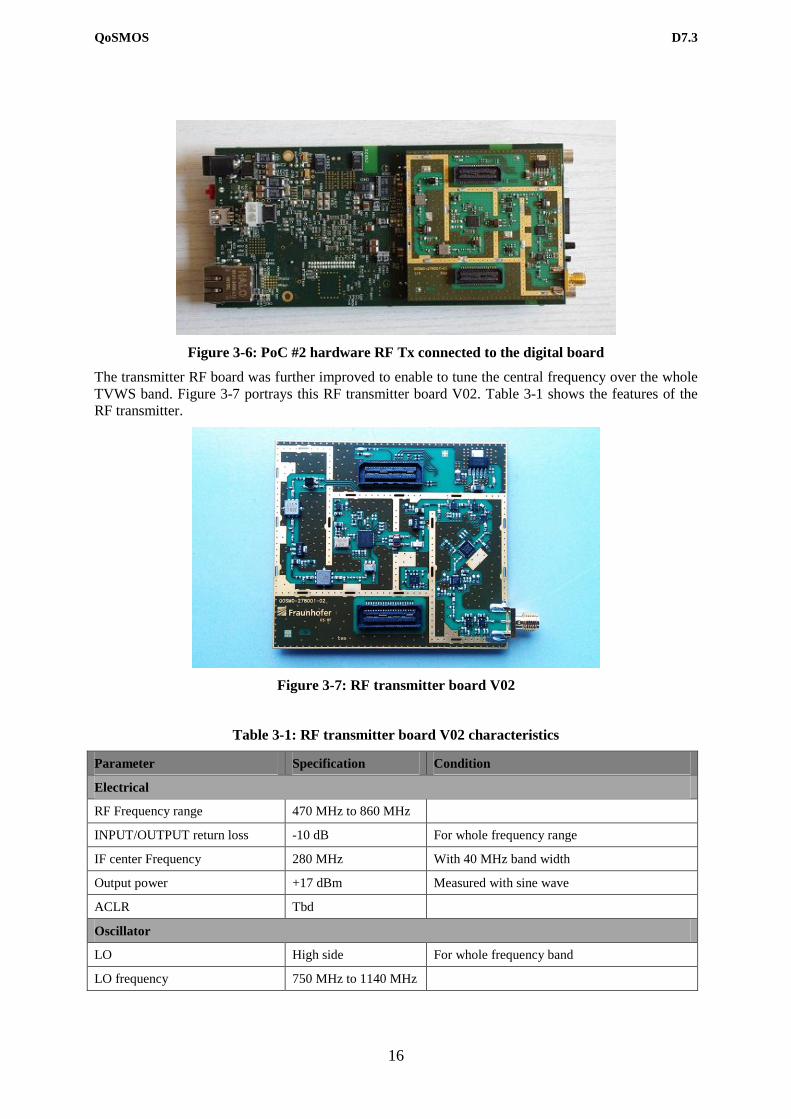
Figure 3-6: PoC #2 hardware RF Tx connected to the digital board
The transmitter RF board was further improved to enable to tune the central frequency over the whole
TVWS band. Figure 3-7 portrays this RF transmitter board V02. Table 3-1 shows the features of the
RF transmitter.
Figure 3-7: RF transmitter board V02
Table 3-1: RF transmitter board V02 characteristics
Parameter Specification Condition
Electrical
RF Frequency range 470 MHz to 860 MHz
INPUT/OUTPUT return loss -10 dB For whole frequency range
IF center Frequency 280 MHz With 40 MHz band width
Output power +17 dBm Measured with sine wave
ACLR Tbd
Oscillator
LO High side For whole frequency band
LO frequency 750 MHz to 1140 MHz
Page 17
QoSMOS D7.3
17
Phase noise -109 dBc/Hz@100kHz For whole chain with sine wave at the input
Mechanical
Physical dimensions 68 mm x 77 mm
Interface
RF output SMA Female
Baseband-Board connector QTE/QSE connector IF IN, Power supply, control
Operating Conditions
Temperature range -40˚C to +85˚C
Supply voltage 3.7 V via SAMTEC connector
Current consumption ca. 470 mA
Reference Frequency
Reference frequency 25 MHz External via SAMTEC connector
Reference input level 800 mVpp
Parameter Specification Condition
Electrical
RF Frequency range 470 MHz to 860 MHz
INPUT/OUTPUT return loss -10 dB For whole frequency range
IF center Frequency 280 MHz With 40 MHz band width
Output power +17 dBm Measured with sine wave
ACLR Tbd
Oscillator
LO High side For whole frequency band
LO frequency 750 MHz to 1140 MHz
Phase noise -109 dBc/Hz@100kHz For whole chain with sine wave at the input
Mechanical
Physical dimensions 68 mm x 77 mm
Interface
RF output SMA Female
Baseband-Board connector QTE/QSE connector IF IN, Power supply, control
Operating Conditions
Temperature range -40˚C to +85˚C
Supply voltage 3.7 V via SAMTEC connector
Current consumption ca. 470 mA
Reference Frequency
Reference frequency 25 MHz External via SAMTEC connector
Reference input level 800 mVpp
Page 18
QoSMOS D7.3
18
The RF receiver board was also designed and tests are ongoing. Figure 3-8 shows the layout of the top
layer of the RF receiver board V01. The RF receiver board hardware is still in production. Table 3-2
gives an overview on the features of the RF receiver.
Figure 3-8: Top-layer layout of the RF receiver board v01
Table 3-2: RF receiver board V01 characteristics
Parameter Specification Condition
Electrical
RF Frequency range 470 MHz to 860 MHz
INPUT/OUTPUT Return loss -10 dB 50 Ohm
IF center frequency 280 MHz With 40 MHz band width
Gain ca. 30 dB Without AGC simulation results
AGC Adjustment range 50 dB In 0.25 dB steps
Noise Figure tbc
Dynamic range tbc
Sensitivity tbc
Oscillator
LO High side For whole frequency band
LO frequency 750 MHz to 1140 MHz
Phase noise tbc
Mechanical
Physical dimensions 68 mm x 77 mm
Interface
RF Input SMA Female
Baseband-Board QTE/QSE connector
from SAMTEC
IF IN, Power supply, control
Operating Conditions
Temperature -40˚C to +85˚C
Supply voltage 3.7 V Single Battery via SAMTEC connector
Current consumption tbc
Reference Frequency
Reference frequency on Board
TCXO
25 MHz External via SAMTEC connector
Reference input level 800 mV p-p
Page 19
QoSMOS D7.3
19
The receiver RX board test is ongoing and the integration with the baseband has not been done yet.
3.2.3 Plan for POC 2 platform completion
The next steps are:
To test the RF transmitter and RF receiver using synthesised signal samples obtained from
simulation. (An integration workshop took place in June 2012, where first tests of the RF Tx
with the baseband were carried out).
To implement an antenna measuring 59 mm by 115 mm by 1 mm for wireless demonstration
within the frequency range from 470 MHz to 860 MHz
To implement the VHDL baseband in order to send actual data over the QoSMOS PHY
To finalize the baseband parameter control via the host machine.
To fine-tune the DAC and RF to achieve high ACLR TX
To show a complete TX/RX communication
3.2.4 POC 2 test plan
Figure 3-9 illustrates the setup for the flexible transmitter demonstration [D7.1]. The characterisation
of the transmitter includes investigations on:
The delay caused by the switching between distinct bands
The signal quality at the transmitter output in comparison to OFDM (spectral leakage, etc.)
Figure 3-9: Architecture of the flexible transmitter demonstration
Figure 3-10 shows the setup for the flexible receiver demonstration [D7.1]. The objectives of the
demonstration of the flexible receiver are as follows:
Evaluation of the sensing performance
o Total time required to sense each channel
o Receiver sensitivity (sensing of weak signals)
Characterization of the receiver
o Time required for switching between distinct bands
o Signal group delay
Page 20
QoSMOS D7.3
20
o Sensitivity
Figure 3-10: Architecture of the flexible receiver demonstration
Figure 3-11 gives an overview of the setup for the flexible transceiver demonstration [D7.1], by
means of which the transceiver unit can be characterised in terms of both its communication
performance and its sensing performance. A demonstration using a wired connection will be
performed, first, followed by a demonstration over the air.
Figure 3-11: Architecture of the flexible transceiver demonstration
3.3 Proof of Concept #3: Distributed/Collaborative Sensing
3.3.1 Reminder of POC 3 goal and functional architecture
This PoC aims at demonstrating the benefit of the distributed sensing algorithms proposed and
developed within WP3. The PoC is composed with three main entities Figure 3-12: data fusion unit,
sensors, and incumbent emulator.
Page 21
QoSMOS D7.3
21
Figure 3-12: PoC 3 Scenario
The hardware sensor is in charge of performing an RF sensing and applying a local decision
algorithm, as well as sending the final decision to the fusion unit.
The software sensor mimics HW sensor behaviour to achieve a large number of sensing nodes.
The data fusion unit is responsible for the generation of the decision on the presence of an IU. This
unit gathers the sensing data from the sensing devices and generate the final decision.
And finally, a Primary Scene Emulator is needed to generate the IU signal that each sensing device
should receive according to the IU service to be detected and the considered channel model.
Figure 3-13: Architecture of the PoC 3
Figure 3-13 presents the main blocks in PoC3 Architecture. The main building blocks of the HW
sensor are the SS-SCTRL and CM-RM-RU. The block SS-SCTRL is responsible for acquiring,
processing, generation the decision and sending it. The block CM-RU-RM is responsible for receiving,
parsing and applying the sensing configuration to the hardware sensor.
The behavior of SW sensor is similar to the HW sensor but the hardware is emulated. The SS-SCTRL
is responsible for receiving the primary emulator pattern, processing, generating the decision and
sending it.
The blocks of the datafusion, located at BS / GW, are the SS-SMGT and CM-MR-RC. The block SS
SMGT is responsible for receiving the decisions of all individual sensors and generating the final
Page 22
QoSMOS D7.3
22
decision that can be reported to the AL. The block CM-RM-CR receives AL configuration and applies
it in the different existing sensors.
The Primary Scene Emulator consists of the blocks CTRL-IT, Primary Emulator and Channel
Emulator.
The Channel Emulator block emulates several independent physical channels. It outputs an
independent signal for each HW sensor. The block Primary Emulator emulates a primary user which is
then subject to different emulated channels and IT-CTRL block controls the Primary Scene Emulator
defining its triggers.
Figure 3-14: Architecture of the Sensor and Datafusion unit
The detailed architecture of the system can be seen in Figure 3-14.
The individual blocks that can be identified in the datafusion depend on the number of sensors:
The datafusion contains one CM-RM-RC instance for each sensor and this instance is in charge of
setting up the sensor configuration via XML-RPC. The SS-SMGT is made up of a set of UDP server
blocks and the QoSMOS Fusion Unit Application. The several UDP server blocks receive the local
sensing decisions from their respective sensor and forward it to QoSMOS Fusion Unit Application,
which generates the final decisions of the presence of IU and displays it (reports it to AL in final
PoC4).
The sensor may be divided into four main blocks:
1. RF Board (USRP Daughterboard)
The RF block resides inside USRP hardware and consists of the RF component, usually referred to as
USRP daughterboard. The block is constituted by an amplifier followed by a mixer (frequency shifter)
with its oscillator and a low pass filter. The input of the block receives the RF signal, via a SMA
Page 23
QoSMOS D7.3
23
connector, and the output is the analog baseband IQ signal (phase and quadrature) with a bandwidth
BW. The Table 3-3 shows the main specification of the different daughterboard’s:
Table 3-3: Main specifications of daughterboard
SBX WBX RFX2400
BW (MHz) 40 40 30
Gain (dB) 31.5 31.5 70
Freq MHz 400 - 4400 50 – 2200 2300 – 2900
Noise Figure (dB) 5-10 5-10 5-10
The relevant parameters to control the daughterboard are:
o Tuning frequency (F): the oscillator frequency which drives the mixer; has a
resolution of a few MHz.
o Gain (G): the amplifier gain used on the sensors is the maximum supported by the
daughterboard to maximize the SNR at the output of block, ie: the input of ADC.
2. Digital baseband (USRP Motherboard)
This block resides inside USRP hardware and its main component is the FPGA; it is usually referred
to as USRP motherboard. Two additional blocks that stand out are the ADC and HOST interface. The
Table 3-4 shows the main specifications of the different motherboard’s:
Table 3-4: Specifications of motherboard
FPGA ADC Host BW Host Interface
B100 Xilinx Spartan 3A-
1400
12bit, 64MSPS
Gain = 0 dB
16 USB 2.0
USRP1 Altera Cyclone
EP1C12Q240C8.
12bit, 64MSPS
0 < Gain < 20dB
16 USB 2.0
USRP2 FPGA Spartan 3-2000 14bit, 100MSPS
Gain = 0 dB
50 GigE
The input ADC receives the analog signal IQ from the daughterboard. Once digitized, the signal is
processed in the FPGA. Inside the FPGA the signal goes to a mixer that allows a fine tune in
frequency. Then the signal is decimated in order to meet the specifications of the bandwidth to be
transferred to the HOST computer. The output of the block goes to the HOST computer via USB 2.0
or Gigabit Ethernet.
The relevant parameters to control the motherboard are:
o Tuning frequency (F): the digital mixer oscillator frequency (when the wanted RF
frequency can’t be tuned by the daughterboard’s RF oscillator, a fine adjustment is
made in the digital mixer in order to center the signal at the desired frequency).
o Decimation (D): decimation value to be used in decimation filters to achieve required
HOST bandwidth.
o (Gain (G): for USRP1 there is a gain in the ADC and thus the overall system gain is
the sum of gains of the ADC and RF stage.)
3. Block Processing Flow
Page 24
QoSMOS D7.3
24
This block resides in the HOST computer and it is here that the detection algorithm is implemented.
The input of the block is the IQ signal coming from the USRP motherboard. This outputs the local
decisions that are encapsulated in UDP packets.
The relevant control parameters of this block are as follows:
o Sensing time (S): defines the period between sensing decisions.
o Samples (N): number of samples used to perform the detection.
o Threshold (T): sets the detector’s decision threshold.
o Network address (N): set the IP addresses and destination ports for UDP stream
4. QoSMOS Sensor Application
This block implements the CM-RM-RU present in the sensors. It receives the configuration, remotely
via XML-RPC, and forwards the parameters to the respective sensor blocks.
3.3.2 Status of the platform for POC 3
Scenario:
The scenario is defined and is composed of the primary scene emulator, the
hard/software sensors and the datafusion unit at the BS/GW.
Scene emulator:
- Main functionalities of the emulator are available and have been tested. We are
now busy working on the spectral re-growth problem happening when ARB files
have to be truncated. We have started with the analysis of it, then we’ll aim at
deriving practical solutions.
Sensors:
The energy sensors are available for integration.
- Low level processing: completed
The low level processing (both RF & Baseband), including the definition of
hardware architecture and GNURadio framework.
- Remote sensor control (CM-RM-RU): completed
The control of the sensor is done remotely by the CM-RM-RC unit. The control is
implemented using XML-RPC.
- Detection algorithms: under development
In the first version of the sensor the implemented algorithm was the energy
detection and we are now implementing the local detection algorithm developed
inWP3.
Datafusion (CM-RM-RC & SS-SMGT):
- Architecture: completed
The architecture of the datafusion is defined and implemented in a multithread
application approach.
- Sensors control: completed
The control of the various sensors is made by the CM-RM-RC over the network
and using XML-RPC.
- Centralized detection algorithm: under development
The initial detection algorithm implemented in the SS-SMGT unit consists in a
bitwise OR operation performed in the sensing data that comes from the all
Page 25
QoSMOS D7.3
25
connected sensors. We are now implementing the centralized detection algorithm
developed inWP3.
- Synchronization of the sensing results’ transmission: under development
There are some issues in synchronizing the sensing data coming from the various
sensors; solving these issues may require changes to the transmission protocol
implemented to send the local sensing data over the network.
3.3.3 Plan for POC 3 platform completion
Scene emulator:
- The remaining work aims at solving or diminishing the spectral regrowth problem
when files are truncated. Analysis is ongoing; solutions will hopefully be later
derived.
Sensors:
- Currently implementing the algorithm coming from WP3. We plan to have it
working before the scheduled integration week in the end of July.
- The transmission protocol may be changed to solve synchronization issues.
Datafusion:
- Currently working to pin-point the source of the synchronization issues. Re-
working the implemented transmission protocol. A simpler protocol that can best
fulfil real-time transmission is being tested.
- In a near future will evolve the centralized decision algorithm to the one
developed in WP3.
3.3.4 POC 3 test plan
The test scenario is composed by the following elements:
o Primary signal emulator
o Channel emulator
o Primary scene emulator control
o HW Sensors
o SW Sensors
o Ethernet switch
o Datafusion
The integration of the different elements is straightforward. The RF input of the sensors is connected
by RF cables to the different outputs of the channel emulator. The transmission over SS0 and RM0
interfaces is implemented over IP. An Ethernet switch connects all sensors to the datafusion. Sensors
and datafusion run in different computers in the same IP network.
One week of tests involving IT and Agilent is scheduled in the end of July. This will cover both PoC1
and PoC3 and will prepare the later-this-year PoC4 integration.
Depending on the results of this week of tests, an extra integration week may be scheduled.
3.4 Proof of Concept #4: Integrated Platform
3.4.1 Reminder of POC 4 goal and functional architecture
POC 4 aims to illustrate a scenario that provides relevance to QoSMOS, integrating developments
achieved in the previous PoCs and showcasing to some extent a real cognitive system. Through its
Page 26
QoSMOS D7.3
26
development, certain Cognitive Radio concepts developed for link and upper layers would be
validated. Among them, the validation of decision making and Adaptation Layer functionalities will
be present, as well as the verification of certain cognitive spectrum manager concepts, the creation,
modification, deployment and revocation of a spectrum portfolio, or the dedicated modification of this
portfolio regarding back-up channel handling requirements.
The efforts are focused on designing and evolving an integrated system test setup rather than dividing
works into two separate proofs of concepts, as was intended in the first instances of the project. Thus,
the targeted scenario involves a TVWS environment, where a cellular legacy system and a TVWS
opportunistic system are combined. In brief, the proposed scenario is composed of four different
sections (seen in Figure 3-15), namely:
Incumbent System: A primary scene emulator in charge of generating primary users signals.
Core Network: A Spectrum Portfolio Repository to provide access to the databases, along
with a CM-SM implementation and the Adaptation Layer to ease the communication among
the blocks in the architecture.
Access Points: A collection of sensors and a cellular network deployed with two base stations:
o Cell 1 using a flexible transceiver, operating in TVWS band.
o Cell 2 (Femtocell) operating in licensed band.
A Cognitive User Equipment composed of
o A Smartphone
o Flexible transceiver for white space operation
Incumbent
System
Cognitive User
Equipment
Access Points
Core Network
Mesh of sensors
Figure 3-15: POC 4 proposed scenario
3.4.2 Status of the platform for POC 4
As aforementioned, POC 4 is divided in four sections which are being developed first before
proceeding to integrate all of them together in a same functional setup. During the initial stage of the
correspondent development, the work done can be clearly divided in these subdivisions.
Page 27
QoSMOS D7.3
27
3.4.2.1 Incumbent System
Composed by the Primary Scene Emulator, in the section devoted to PoC #1 it has been established
that its role is to provide a realistic radio scenario where the rest of QoSMOS architecture blocks can
perform.
In addition, some energy based sensors will be used in this PoC to face the PSE stimulus signal and
contribute in the overall test setup performance.
3.4.2.2 Core Network
Regarding the Adaptation Layer, its role in this POC 4 will comprise two main aspects which are
event-subscription functionalities and the capability of carrying out message dispatching duties. The
AL will act as an intermediary between the other two QoSMOS entities present in the Core Network,
the CM-SM and the Portfolio, which are about to ask for and share some information, providing them
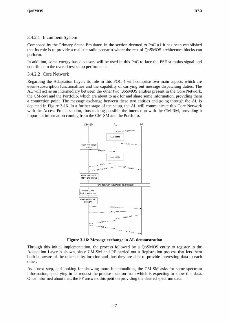
a connection point. The message exchange between these two entities and going through the AL is
depicted in Figure 3-16. In a further stage of the setup, the AL will communicate this Core Network
with the Access Points section, thus making possible the interaction with the CM-RM, providing it
important information coming from the CM-SM and the Portfolio.
Figure 3-16: Message exchange in AL demonstration
Through this initial implementation, the process followed by a QoSMOS entity to register in the
Adaptation Layer is shown, since CM-SM and PF carried out a Registration process that lets them
both be aware of the other entity location and thus they are able to provide interesting data to each
other.
As a next step, and looking for showing more functionalities, the CM-SM asks for some spectrum
information, specifying in its request the precise location from which is expecting to know this data.
Once informed about that, the PF answers this petition providing the desired spectrum data.
Page 28
QoSMOS D7.3
28
This initial trial includes the implementation of two simple graphic interfaces representing the entities
involved in the information exchange, in this case the CM-SM and the PF as is shown in Figure 3-17.
Figure 3-17: Graphic interfaces in AL demonstration
The map on the CM-SM interface represents the area where the channels information is desired, also
differentiating among four different zones where the user could be located. The text logs offer a
detailed timeline of the process, beginning with the entities registration in the AL and continuing with
the diverse information that is sent from one to another.
In addition, another preliminary trial includes the testing of the Portfolio alone, for which a similar
scenario to the one above has been designed, focusing in the channels available all along the Great
Britain. The user can select a certain rectangular area on the GB map and the system will answer back
with both a collection of free channels and their correspondent power as well as with a drawing where
the different channels offered on that zone are painted with different colours, depending on the number
of them available. This graphic representation can be appreciated in the Figure 3-18, where the
selected area appears near the down right corner of the image.
Page 29
QoSMOS D7.3
29
Figure 3-18: Portfolio informing about available channels in GB
3.4.2.3 Access Points
The access point is made of two parts:
The NEC Femto Access Point (FAP) is a ‘zero touch’ plug-and-play consumer device made
by Ubiquisys which provides the 3G legacy network.
The transceiver which provides the wireless link extension in TVWS.
The NEC Femto Access Point (FAP), depicted in Figure 3-19, is installed at the subscriber premises
and connects to the operator’s core network over the subscriber’s broadband connection by using an
Ethernet connection. The FAP provides localized 3G coverage and dedicated capacity in a home
enhancing the end user experience through improved Quality of Service (QoS). The Table 3-5 below
shows the main specifications of the NEC FAP:
Table 3-5: Specification of the Femto Access Point
Standards 3GPP Release 5 2005-06
Range 200 m maximum
Voice Channel Up to four users
Data Channels
64 kbps bi-directional (four users)
128 kbps downlink and 64 kbps uplink (four
users)
324 kbps downlink and 128 kbps uplink (two
users)
384 kbps downlink and 324 kbps uplink (one
user)
HSDPA support User Equipment categories 1-8, 11 and 12
Peak HSDPA rate 3.6 Mbps
Frequency bands Receive : 1920 MHz to 1980 MHz
Page 30
QoSMOS D7.3
30
Transmit : 2110 MHz to 2170 MHz
Transmit Power 10 dBm maximum
Ethernet Interface 10/100 RJ-45 Ethernet port
Number of antennas 1 (internal)
Power +6V DC at 2.5A maximum
Figure 3-19 : NEC FAP a) side view b) view from behind
The FAP interworks with the legacy 3G handsets using the 3rd Generation Partnership Project (3GPP)
Uu interface. The FAP connects over the broadband to the RAN GW using the 3GPP standard Up
interface as described below:
It has a (U)SIM dedicated to the access point provisioning, configuration, authentication with
the core network and to support UMTS services for the home number service.
It provides local UMTS coverage at 3GPP standards.
It interfaces with multiple Universal Equipments (UEs) over the 3GPP standard Uu interfaces,
terminating locally Access Stratum (AS) and Non Access Stratum (NAS) layers. The UEs are
3GPP standard UMTS UEs and require no additional client. There is no restriction on the type
of terminal used - they can be handsets, Personal Digital Assistants (PDAs), Personal Computer
(PC) cards or any other form factor.
It supports terminal adaptation and is capable of allowing home number calls to be made using
Plain Old Telephone Service (POTS) or Session Initiation Protocol (SIP) phones.
The PC client allows the end user to control local services preferences, contacts and dynamic
calls/sessions behaviour. Softphone functionality can be included in the PC client and used to
make outgoing home number calls.
The following are types of configuration settings that could be configured via the Graphic User
Interface (GUI):
Page 31
QoSMOS D7.3
31
Baseline Service Configuration:
o Mobile Country Code (MCC) and Mobile Network Code (MNC)
o IP Security (IP Sec)
o UMA or IMS settings
o Homezone Name
o Operations and Maintenance (O&M) baseline configuration
Customer/Subscription Service Configuration (i.e. per customer settings)
o Address, Post Code
o Public Land Mobile Network (PLMN) Cell Identity (ID)
o Neighbour Cell List
o Access (subscriber Universal Equipments (UEs)) List
Dynamic Service Configuration:
o Radio Frequency (RF) Profile (e.g. allowed frequencies, allowed scrambling codes,
Location Area Code (LAC) ranges)
The transceiver, in charge of facilitating the communications in the TVWS is currently being
developed and tested, as is shown in Section 3.2. Its functionality is being consolidated in POC 2
through the execution of diverse tests looking to validate the developed equipment,
In addition, various trials have been executed with the sensors used in the scenario, creating a mesh
with all of them and obtaining sensing reports that are going to be shared with other entities in the
QoSMOS architecture. The current status can be checked in Section 3.3, showing that the validation of
POC1 and POC3 is taking place at the moment, and the next steps involve the addition of this work
within the integrated setup.
3.4.2.4 User Equipment
This section of the test setup will include and Smartphone working with an Android OS which will be
the device trying to connect to the different TVWS channels and/or the legacy system. It will contact
with the transceiver through a wireless link, thus being able to receive any necessary updates.
The User Equipment will contact the Access Point section in the test setup through a Wi-Fi AP
dedicated to this task.
3.4.3 Plan for POC 4 platform completion
The set-up of the Femto BS is illustrated below in Figure 3-20. In particular the following components
are available and have been set-up and configured to allow the Femto BS operating in an autonomous
manner without any need for a RAN gateway:
Wireshark Debug Tool,
Initial Configuration interface via HTTP,
User and Session Management.
Page 32
QoSMOS D7.3
32
HTTP tool for initial configuration
(RF channel, Tx pwr, access rights…)
•SIP Server , ensuring authentication and session management
User & session Management
NEC Femto AP
Debug tool : Wireshark
IP router
Ethernet link
Figure 3-20: Femto BS Set-up.
The work related to the set-up of the Femtocell is complete. It allows attaching NEC smartphones and
browsing from the smartphone a web server located in a local Ethernet network and playing streaming
video in the smartphone. This first set-up is depicted below in Figure 3-21:
Bluetooth
stackTRX (3G)
Femtocell
NEC Android
Smartphone
Wifi
stack
BROWSER
Ethernet stack
DHCP
Laptop#1: Femto set-up
SIP
Management
Linux
Ethernet stack
Laptop#2: Application server
Web server
Linux
Figure 3-21: Femto test phase.
Furthermore, a great amount of work is going to be carried out on the Adaptation Layer side, given its
condition of intermediary among several QoSMOS entities. Thus, the immediate next step consists in
making a real interaction with partners in charge of developing CM-SM instances and PF within the
Core Network, as well as with entities in the Access Point section like the CM-RM and the sensors in
charge of making the distributed sensing and send the correspondent sensing reports.
The work on that first part of the completion has already started. Thus, a detailed definition of the
interfaces among entities has been carried out, on the one side clearly depicting the AL1 interface that
will permit the interaction between the CM-SM and the AL, and on the other hand preparing a first
Page 33
QoSMOS D7.3
33
version of a demonstration that integrates the ones presented in Section 3.4.2.2. This way, a CM-SM
entity asks for information on the available channels in a certain location, using to this end a map
where an exact position is selected. This request goes to the Portfolio through the AL, which acts also
on the way back of the requested data. In the end, the user will obtain the desired information: a
graphic appearing on a web interface detail the available frequencies and their powers, while at the
same time the most valid one will be picked and presented in a dedicated section in order to ease the
user to select the proper frequency to use.
Figure 3-22 below shows a screenshot of the web application where the request of info about a
concrete location is made (in this case, south GB) and then information regarding the available
channels is presented.
Figure 3-22: Demo on Core Network entities interactions
This way a real interface implementation will be carried out and it will be possible to simulate
different situations involving the AL, like the registration / deregistration of different entities or the
exchange of information messages, updating the rest of entities in the process.
In addition, the communication between the transceiver and the rest of entities in the Access Points
and the User Equipment sections is going to be validated, both in TVWS and in a physical plane,
while at the same time the application to be transmitted will be designed. In order to carry out these
tasks, it is necessary to count on a proper set of interfaces among the diverse blocks involved, which
have been already defined and are ready to their testing and validation.
3.4.4 POC 4 test plan
In the end, this POC will illustrate a scenario where an opportunistic UE does handovers between
TVWS bands, and/or between TVWS and licensed cellular system. As a first step in the demonstration
scenario a TWVS link will be established between a ‘terminal’ and a ‘base station’, thus showing the
CM-RM TV channel selection in the TVWS band exploiting portfolio data and the TVWS PHY with a
point to point link, while at the same time the spectrum could be also shown on a spectrum analyzer.
Then, an Incumbent system is detected, acting an update of the Database as a trigger and the entities
communicating over the air in an UHF channel.
The hardware sensors contribute to carry out a distributed sensing, so information about channel
options is given and CM-RM decides whether it is necessary to carry out an Eviction process to a
Page 34
QoSMOS D7.3
34
second UHF channel, or it is better to stay in the same one it was previously operating or maybe going
to legacy.
Once this process is finished, a new Incumbent User enters the network. The system is able to detect
the QoS drops, and the moment the CM-RM is informed another Eviction process is triggered. Finally,
the terminal does a handover to a TVWS backup channel or a licensed cellular system. This way, the
CM-RM eviction control in the TVWS is demonstrated, and a vertical cross-system handover is
performed.
Through the execution of the different steps of this demonstration scenario, several interactions among
different QoSMOS architecture entities will be showcased, while also putting into practice some
functionalities hinted in the theoretical work packages.
Page 35
QoSMOS D7.3
35
4 Conclusions
QoSMOS has a clear plan to portray its activities into demonstrators. This plan consists of a set of 4
Proof Of Concepts which development is ongoing. This document provides the status of these PoCs.
This activity will continue until the end of the project where a final prototype will be provided in D7.4.
The way forward to reach this final version is provided in this document along with the test plan.
Integration workshops will be organized amongst partner to ease the integration phase. Such
integration meetings already took place and enabled to achieve partial demonstrations at the year 2
review and at the Future Networks and Mobile Summit in Berlin.
Page 36
QoSMOS D7.3
36
References
[D7.1] QoSMOS Deliverable D7.1, “Platform architecture definition (1/2)”,
Dec. 2010.
[D7.2] QoSMOS Deliverable D7.2, “Platform architecture definition (1/2)”,
Dec. 2011.
[Berg12]
V. Berg, D. Noguet and X. Popon, A Flexible Hardware Platform for
Mobile Cognitive Radio applications, Euromicro DSD 2012, Turkey
Sept. 2012 (accepted paper).