44
QTech Workbench User Manual Version 2.0

QTech Workbench
User Manual
Version 2.0
QTech Workbench – User Manual
2
Contact QTech .................................................................................................................. 4
Revision Details ................................................................................................................ 4
Introduction ..................................................................................................................... 5 This User Guide ........................................................................................................................ 5 Intended audience for this Guide .............................................................................................. 5 What is “QTech Workbench” .................................................................................................... 5
Getting started ................................................................................................................. 6 How to install ........................................................................................................................... 6 Equipment required ................................................................................................................. 6
User Interface................................................................................................................... 7 Layout of the Application ......................................................................................................... 7
Configuring a Device ......................................................................................................... 8 Selecting a Device Type ............................................................................................................ 8 Open/Save a Configuration File ................................................................................................ 9 Offline Editing .......................................................................................................................... 9 Online Editing ........................................................................................................................ 10 Help ....................................................................................................................................... 10
Q04 Plus on XL4-RTU ...................................................................................................... 11 Overview ............................................................................................................................... 12
Power Supply Alarm Configuration ............................................................................................... 13 Ethernet ........................................................................................................................................ 14 Licencing ........................................................................................................................................ 15 Diagnostics .................................................................................................................................... 16 DLP ................................................................................................................................................ 16
Comms Options ...................................................................................................................... 18 DATRAN ......................................................................................................................................... 19 Expansion Modules ....................................................................................................................... 23 General Purpose I/O ..................................................................................................................... 24 Modbus Slave ................................................................................................................................ 26 Modbus Master ............................................................................................................................. 27
Input / Output........................................................................................................................ 29 Digital Inputs ................................................................................................................................. 30 Digital Outputs .............................................................................................................................. 31 Analogue Inputs ............................................................................................................................ 32 Analogue Outputs ......................................................................................................................... 33
RTU Input / Output ................................................................................................................ 34 Analogue Configuration ................................................................................................................ 34 Analogue Calibration ..................................................................................................................... 34 Digital Configuration ..................................................................................................................... 37
Data Logging .......................................................................................................................... 37 Firmware Upload ................................................................................................................... 38
Programming XL4 .......................................................................................................................... 38
Configuring the RTU - Workflow for a typical configuration ............................................. 40 XL4 plus with Modbus & Dual Base Comms ............................................................................. 40 Ethernet Port Configuration .................................................................................................... 40

QTech Workbench – User Manual
3
Serial Port Configuration ........................................................................................................ 42 Modbus Configuration ............................................................................................................ 43
QTech Workbench – User Manual
4
Copyright 2017 to QTech Data Systems Limited
Christchurch, New Zealand
All rights reserved
The circuit details and know how disclosed in this document are proprietary to QTech Data Systems Limited and shall remain the intellectual property of QTech Data Systems Limited.
DISCLAIMER
The information in this document is subject to change without notice and does not represent a commitment on any part of QTech Data Systems Limited. While the information contained herein is
assumed to be accurate, QTech Data Systems Limited assumes no responsibility for any errors or omissions.
Contact QTech QTech Data Systems Limited 12 Midas Place, Middleton Christchurch 8024 New Zealand Phone: +64-3-366-3713 Fax: +64-3-365-2815 www.qtech.co.nz
Revision Details 1.0 May 2012 Initial Issue
1.1 June 2012 Amended jumpers for Rev D & addition of upgrade section
2.0 September 2017 Revisions for DATRAN XL4 RTU running Q04 Plus firmware
QTech Workbench – User Manual
5
Introduction
This User Guide
This document provides help specifically for configuration of Q04 Plus firmware features.
Additional help can be found at www.qtech.co.nz where application notes can be obtained to provide guidance for specific configuration scenarios, detailing the configuration workflow steps.
Context sensitive help is provided on the screen for category forms or parameters.
Note: The DATRAN XL4 Plus RTU provides hardware enhancements to the XL4 RTU and operates QTech Q04 Plus firmware on a Real-Time Operating System platform. The configuration requirements and features are different from the DATRAN XL4 RTU running Q04 firmware.
Intended audience for this Guide
This guide assumes that you have been trained on and are familiar with QTech Data Systems RTU products, their configuration and their terminology. It is designed as a reference guide to using QTech’s configuration and diagnostics software. Please refer to other QTech Data Systems resources for introductory training material or specific Owners Manual’s for detailed descriptions of each product.
What is “QTech Workbench”
QTech Data Systems has a range of RTU products. The software/firmware running on these products must be configured for correct operation. Workbench is a software tool for configuring and providing diagnostics on any fourth generation QTech Data System RTU products. Configurations can be sent directly to a connected RTU (online) or saved to a file for later transfer (offline).
Version 2.x or later, of Workbench has been redesigned specifically to
include the configuration of Q04 Plus firmware, a real-time operating system for the XL4
RTU.
simplify the user interface to be more function based
Note: Firmware upgrades to the XL4 can be undertaken using Workbench version 2.x or later. To upgrade your Q04 software to Q04 Plus, refer to the APPLICATION NOTE Upgrading Q04 firmware to Q04 Plus on XL4 RTU.

QTech Workbench – User Manual
6
Getting started
How to install
The QTech Workbench software is free to download from the QTech Website (http://www.qtech.co.nz/shop/SCADA+Supervisory+Control+and+Data+Acquisition.html). There are two versions of the installation file. The DN version contains Microsoft .NET framework 2.0 bundled. If you already have .NET Framework installed on your PC, install the non DN version
Run the installer and accept the software licencing agreement.
Equipment required
USB cable
To configure any RTU you will need to connect it to your PC via a USB cable (Type A to Type B).
USB Drivers
When connecting to the RTU the first time using Workbench, the correct USB driver must be installed. Ensure that the device driver is completely installed before attempting to connect to the RTU using Workbench. If the PC running Workbench is connected to the internet, then the WHQL certified driver from Microsoft will automatically be downloaded and installed. The virtual com port device driver can also be downloaded from the manufacturer FTDI (http://www.ftdichip.com/Drivers/VCP.htm).
QTech Workbench – User Manual
7
User Interface
Layout of the Application
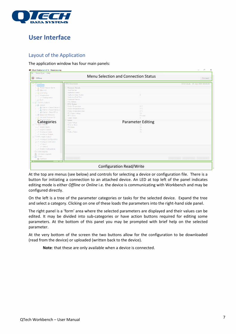
The application window has four main panels:
At the top are menus (see below) and controls for selecting a device or configuration file. There is a button for initiating a connection to an attached device. An LED at top left of the panel indicates editing mode is either Offline or Online i.e. the device is communicating with Workbench and may be configured directly.
On the left is a tree of the parameter categories or tasks for the selected device. Expand the tree and select a category. Clicking on one of these loads the parameters into the right-hand side panel.
The right panel is a ‘form’ area where the selected parameters are displayed and their values can be edited. It may be divided into sub-categories or have action buttons required for editing some parameters. At the bottom of this panel you may be prompted with brief help on the selected parameter.
At the very bottom of the screen the two buttons allow for the configuration to be downloaded (read from the device) or uploaded (written back to the device).
Note: that these are only available when a device is connected.
Categories Parameter Editing
Menu Selection and Connection Status
Configuration Read/Write
QTech Workbench – User Manual
8
Configuring a Device You can work Offline, where you can edit/create configuration files for later download to a device. If a device is connected to your PC you can work Online, where you can edit/create configuration files and/or configure the device directly.
In Offline mode, you need to:
1. select a device
2. open an existing configuration file (optional)
3. select each category and edit the parameters
4. save the configuration file.
In Online mode, you will need to:
1. Connect to the device
2. Read the configuration from the device, or open an existing configuration file
3. select each category and edit the parameters
4. Write the configuration file to the device and/or save the configuration file
Selecting a Device Type
A device type can be selected either from the Device Type menu, for offline editing, or if physically connected via USB and powered can be automatically detected using the Connect button.
For offline editing, you can select the desired device from the Device Type menu. This menu is only available in Offline mode. Once the device type has been selected the user interface will only display the category tree appropriate for that particular device.
Other devices configured by this software include:
Cellular Data Logger
DATRAN XL4 RTU
DATRAN Q04 Plus RTU
Multi Point Controller
QTech Digital Radio
Security Access Controller
SAC-050
SMS-Lite
Refer to the specific user guide for these products for further information
Select Device type DATRAN Q04 Plus RTU for the following:
DATRAN XL4 RTU hardware that has been firmware upgraded from Q04.
DATRAN XL4 Plus RTU hardware.

QTech Workbench – User Manual
9
Open/Save a Configuration File
Configuration files have a unique file extension for each device E.g. a *.QDR configuration file will contain QDR configuration etc. So, to open a configuration file for a device you must first select the device type. For offline editing you can select the desired device from the Device Type menu.
Under the File menu:
Open - this will allow you to browse for and load an existing configuration file
Save - allows the configuration to be saved to the network.
Exit - quits this configuration tool.
Offline Editing
The Workbench configuration tool allows you to edit and manage your device configuration without the device connected. In offline mode, a configuration file can be created and saved to the network. Next time you are in online mode with a device connected you can then load your settings from your hard drive and then upload them to your device using the Write to Device button at the bottom of the screen.
Select a device From the Device Type menu, select the device type you wish to configure e.g. DATRAN Q04 Plus RTU. The category tree available for the selected device will be shown down the left hand side panel.
Open an existing configuration file (optional) You can open and edit an existing configuration file. Configuration files have a unique file extension for each device E.g. a *.QDR configuration file will contain QDR configuration. To edit an existing configuration file, you must first select the device type
Select each category and edit the parameters On selecting any category the parameters of the device will be editable in the window on the right hand side panel. It may be divided into sub-categories or have action buttons required for editing some parameters. At the bottom of this panel you may be prompted with brief help on the selected parameter.
Save the configuration file. Under the File menu select Save. Name your file with a unique and meaningful name. The
configuration file extension is appended automatically.
QTech Workbench – User Manual
10
Online Editing
To configure a device connected to your PC, you will need to ensure the device is connected via USB and powered.
Note: If you haven't connected to a QTech USB device before from this computer you will need to install the correct USB driver first (see above)
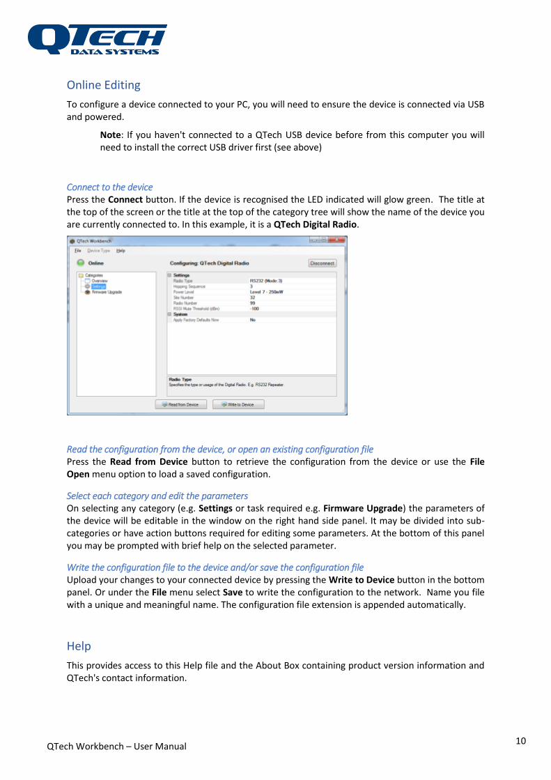
Connect to the device Press the Connect button. If the device is recognised the LED indicated will glow green. The title at the top of the screen or the title at the top of the category tree will show the name of the device you are currently connected to. In this example, it is a QTech Digital Radio.
Read the configuration from the device, or open an existing configuration file Press the Read from Device button to retrieve the configuration from the device or use the File Open menu option to load a saved configuration.
Select each category and edit the parameters On selecting any category (e.g. Settings or task required e.g. Firmware Upgrade) the parameters of the device will be editable in the window on the right hand side panel. It may be divided into sub-categories or have action buttons required for editing some parameters. At the bottom of this panel you may be prompted with brief help on the selected parameter.
Write the configuration file to the device and/or save the configuration file Upload your changes to your connected device by pressing the Write to Device button in the bottom panel. Or under the File menu select Save to write the configuration to the network. Name you file with a unique and meaningful name. The configuration file extension is appended automatically.
Help
This provides access to this Help file and the About Box containing product version information and QTech's contact information.

QTech Workbench – User Manual
11
Q04 Plus on XL4-RTU
Power the DATRAN XL4 RTU and connect it to the PC via the USB port. Pressing the Connect button on the user interface will now display the Overview information as follows:
The above screenshot shows the DATRAN variant of the DATRAN XL4 RTU running the real-time operating system Q04 Plus.
QTech Workbench – User Manual
12
Overview
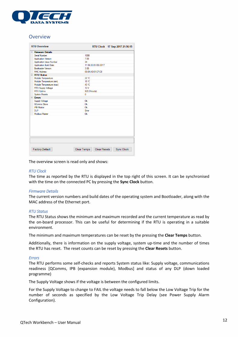
The overview screen is read only and shows:
RTU Clock The time as reported by the RTU is displayed in the top right of this screen. It can be synchronised with the time on the connected PC by pressing the Sync Clock button.
Firmware Details The current version numbers and build dates of the operating system and Bootloader, along with the MAC address of the Ethernet port.
RTU Status The RTU Status shows the minimum and maximum recorded and the current temperature as read by the on-board processor. This can be useful for determining if the RTU is operating in a suitable environment.
The minimum and maximum temperatures can be reset by the pressing the Clear Temps button.
Additionally, there is information on the supply voltage, system up-time and the number of times the RTU has reset. The reset counts can be reset by pressing the Clear Resets button.
Errors The RTU performs some self-checks and reports System status like: Supply voltage, communications readiness [QComms, IPB (expansion module), Modbus] and status of any DLP (down loaded programme)
The Supply Voltage shows if the voltage is between the configured limits.
For the Supply Voltage to change to FAIL the voltage needs to fall below the Low Voltage Trip for the number of seconds as specified by the Low Voltage Trip Delay (see Power Supply Alarm Configuration).
QTech Workbench – User Manual
13
For the Supply Voltage to return back to OK the voltage has to be above the Alarm Reset Voltage for the number of minutes as specified by the Alarm Reset Delay(see Power Supply Alarm Configuration).
Factory Defaults Factory defaulting the RTU will return all settings back to their default values. Pressing the Factory Default button will warn and prompt you if you are sure before the settings are defaulted.
Warning: This will clear any custom configuration that you have made to your RTU.
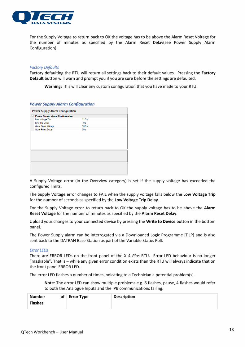
Power Supply Alarm Configuration
A Supply Voltage error (in the Overview category) is set if the supply voltage has exceeded the configured limits.
The Supply Voltage error changes to FAIL when the supply voltage falls below the Low Voltage Trip for the number of seconds as specified by the Low Voltage Trip Delay.
For the Supply Voltage error to return back to OK the supply voltage has to be above the Alarm Reset Voltage for the number of minutes as specified by the Alarm Reset Delay.
Upload your changes to your connected device by pressing the Write to Device button in the bottom panel.
The Power Supply alarm can be interrogated via a Downloaded Logic Programme [DLP] and is also sent back to the DATRAN Base Station as part of the Variable Status Poll.
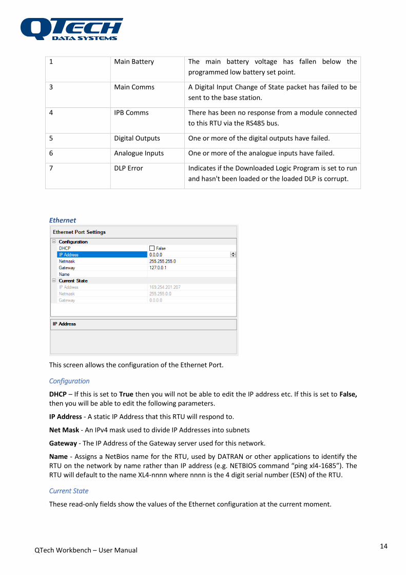
Error LEDs There are ERROR LEDs on the front panel of the XL4 Plus RTU. Error LED behaviour is no longer “maskable”. That is – while any given error condition exists then the RTU will always indicate that on the front panel ERROR LED.
The error LED flashes a number of times indicating to a Technician a potential problem(s).
Note: The error LED can show multiple problems e.g. 6 flashes, pause, 4 flashes would refer to both the Analogue Inputs and the IPB communications failing.
Number of
Flashes
Error Type Description
QTech Workbench – User Manual
14
1 Main Battery The main battery voltage has fallen below the
programmed low battery set point.
3 Main Comms A Digital Input Change of State packet has failed to be
sent to the base station.
4 IPB Comms There has been no response from a module connected
to this RTU via the RS485 bus.
5 Digital Outputs One or more of the digital outputs have failed.
6 Analogue Inputs One or more of the analogue inputs have failed.
7 DLP Error Indicates if the Downloaded Logic Program is set to run
and hasn't been loaded or the loaded DLP is corrupt.
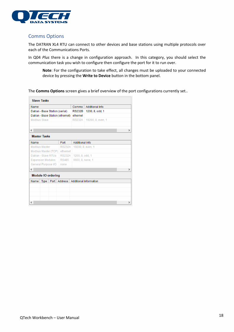
Ethernet
This screen allows the configuration of the Ethernet Port.
Configuration
DHCP – If this is set to True then you will not be able to edit the IP address etc. If this is set to False, then you will be able to edit the following parameters.
IP Address - A static IP Address that this RTU will respond to.
Net Mask - An IPv4 mask used to divide IP Addresses into subnets
Gateway - The IP Address of the Gateway server used for this network.
Name - Assigns a NetBios name for the RTU, used by DATRAN or other applications to identify the RTU on the network by name rather than IP address (e.g. NETBIOS command “ping xl4-1685”). The RTU will default to the name XL4-nnnn where nnnn is the 4 digit serial number (ESN) of the RTU.
Current State
These read-only fields show the values of the Ethernet configuration at the current moment.

QTech Workbench – User Manual
15
Upload your changes to your connected device by pressing the Write to Device button in the bottom panel.
Licencing
The XL4 Plus RTU firmware uses a Real-Time Operating System (RTOS) to organise the various aspects of the RTU functionality into separate tasks. There is a task for reading the digital inputs, a task for communicating with DATRAN, a task for polling MODBUS slaves, and numerous others. In the RTU there are core tasks (IPB Master, QCOMMS master, and QCOMMS Slave/Server) that always run, and optional tasks that are only started if they are enabled in the RTU configuration file.
Each XL4 Plus RTU must have a valid licence installed before any of the optional task can be started. If a user has configured a task to be enabled, but that task has not been licenced, then the RTU will output an error message on start-up (Error: Task x is enabled but not licenced), and not start the task.
Note: If you need an optional task enabled please contact QTech for a Licence Code.
Once you have received your Licence Code enter it in the box as shown above, select the appropriate options tick boxes and press Write Licence to update your firmware.
For a detailed explanation of licencing refer to the document “XL4 Plus Licencing System.docx”
Selecting the Read Licence button will download an existing licence from the RTU, if one exists. The licence will be decrypted and indicate the features which are enabled.
When a new Licence Code is entered, you must upload it to the RTU, using the Write Licence button, before the feature will be enabled.

QTech Workbench – User Manual
16
Diagnostics
The Diagnostics window presents a log of system debug messages. - the above image shows some of debug messages logged when a DATRAN XL4 reboots.
The Clear button will clear the diagnostics window.
The Export button will write the contents of the diagnostics window to *.CSV file on the network.
Diagnostic Configuration
This presents the categories of debug parameters that will be sent by the RTU and consequently shown in the diagnostics panel.
Selecting a category as Enabled will tell the RTU to send diagnostics messages of that category until the next reboot.
Selecting a category as Persistent will tell the RTU that the enabling should persist across reboots.
The guideline is: enable categories if you are debugging and want them to be disabled on next reboot; persist them if they need to be permanently enabled through reboots.
If a category is not Enabled or Persistent, no diagnostics messages will be sent by the RTU.
DLP

QTech Workbench – User Manual
17
With a Downloadable Logic Program (DLP) you can manipulate or generate IO both to the telemetry system and to the real world. It uses a programming language based on either mnemonics or ladder logic that can be compiled and executed on the DATRAN XL4 RTU. They are created using the DLP IDE available from QTech.
The Write DLP to Device button provides a mechanism for copying the DLP from the PC to the RTU. Once loaded the DLP can be Started/Stopped or Cleared completely with associated buttons. Also, an existing DLP can be copied from the device and stored on the network using the Read LDP from Device.
The DLP runs in its entirety, periodically as specified by the DLP Rate property. This rate can be between 50 and 2500 milliseconds
DLP State indicates if a DLP is present on the device.
DLP Run indicates if the loaded DLP is running or paused.
QTech Workbench – User Manual
18
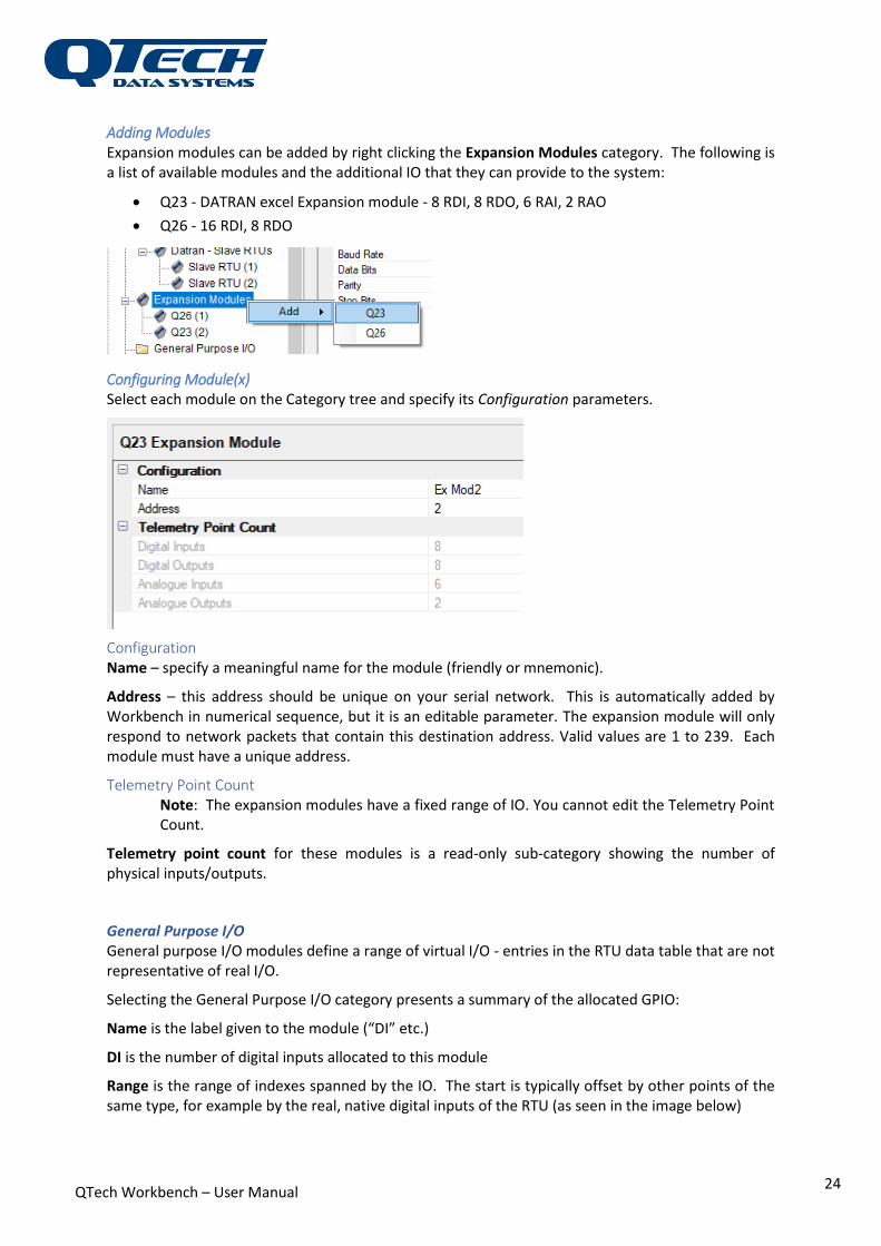
Comms Options
The DATRAN XL4 RTU can connect to other devices and base stations using multiple protocols over each of the Communications Ports.
In Q04 Plus there is a change in configuration approach. In this category, you should select the communication task you wish to configure then configure the port for it to run over.
Note: For the configuration to take effect, all changes must be uploaded to your connected device by pressing the Write to Device button in the bottom panel.
The Comms Options screen gives a brief overview of the port configurations currently set..

QTech Workbench – User Manual
19
DATRAN This category defines how the RTU is connected with the DATRAN SCADA system. Define the protocol and ports used for communications
DATRAN – Base station (serial)
This category is used to specify the connection to the DATRAN SCADA system is via a serial protocol. Connection can be either a direct RS232 or over third party bridges e.g. RS232 to Ethernet or RS232 over Q71 FSK Radio etc.
Configuration. Address - this is the RTU address and should be unique on your radio network. The RTU will only respond to network packets that contain this destination address. Valid values are 1 to 239.
Communication Port – specify the serial port to use {RS232A/B}.
Equipment – specify what external bridges are used, if any. This is currently limited to (Transparent, Q71, Tait Radio, and CM910). Additional parameters may be displayed for you to specify, depending on the equipment selected.
Timing Settings and Serial Port Settings These must be selected and specified.
Lead-In Bytes - The number of header bytes (0xFF) that are sent preceding a network packet (Range 1-16)
Lead-Out Bytes - The number of trailer bytes (0x00) that are sent following a network packet (Range 0-16)

QTech Workbench – User Manual
20
Retries
If the connection to the remote device is lost the RTU will attempt to reconnect [Max Attempts] times with a Short Retry Delay between retries. Thereafter it will attempt to reconnect indefinitely every [Long Retry Delay] seconds.
Serial Port Settings
Drop down boxes providing standard Baud Rates, Parity and Stop bits can be selected.
DATRAN – Base station (Ethernet)
This category is used to specify the connection to the DATRAN SCADA system is via an Ethernet protocol. The configurable parameters are as follows. The port address and mask settings are specified in the Ethernet Category.
Configuration Address - this is the RTU address and should be unique on your radio network. The RTU will only respond to network packets that contain this destination address. Valid values are 1 to 239.
TCP Port - When used in TCP Server mode, this is the Port that this RTU will listen on for incoming connections. Note that changing this setting will require the RTU to be reset before the change takes effect.
Timing Settings COS (Change of State) – specifies whether the RTU will send change-of-state messages
TCP Keep-Alive Interval – specifies how often the base station is polled to verify that the TCP connection is still open (range is 5 – 86400sec)
DATRAN – Slave RTU’s This option enables the RTU to act as a Master to poll and retrieve I/O data from one or more Slave devices.

QTech Workbench – User Manual
21
Configuration Enable – To enable polling and retrieval of I/O data from devices that use QComms, this parameter needs to be set to TRUE. If set to FALSE, the task does not execute and devices that use QComms are NOT polled for data.
Communication Port - The slave devices connect via the serial port. Select which port (RS232A/B).
Equipment – specify what external bridges are used, if any. This is currently limited to (Transparent, Q71, and Tait Radio). Additional parameters may be displayed for you to specify, depending on the equipment selected.
Timing settings Lead-In Bytes - The number of header bytes (0xFF) that are sent preceding a network packet (Range 1-16)
Lead-Out Bytes - The number of trailer bytes (0x00) that are sent following a network packet (Range 0-16)
RTU ACKs COS – in the case of slave-over-radio-link, specifies if the Master RTU or the radio base station should be responsible for acknowledging a change-of-state message from slave RTUs.
RTU Controls Outputs – in the case of slave-over-radio-link, specifies if the RTU or the radio base station should control the outputs of the slave devices.
Serial Port Settings Drop down boxes providing standard Baud Rates, Parity and Stop bits can be selected.
Notional Point Count Notionals are a “General Purpose” data type which is used exclusively by the QCOMMS protocol. These are data points that do not represent physical (Real) input. They may be set-points or counters or parameters derived in a DLP. You may want these to be externally accessible as upstream facing data points. You must reserve space in the RTU IO map.
Specify the master’s notional point count.

QTech Workbench – User Manual
22
Configuring Slave RTU(x) Slaves can be added by right clicking the DATRAN – Slave RTUs category
For example:
Configuration Name – specify a meaningful name for the slave RTU.
Address – this address should be unique on the slave RTU network. This is automatically added by Workbench in numerical sequence, but it is an editable parameter. The slave will only respond to network packets that contain this destination address. Valid values are 1 to 239.
Timing Settings The Master can be set to regularly poll the slave for data. Select if you want Poll Enabled and the Poll Interval.
Maximum Attempts – configures the number of attempts made to communicate with the slave RTU before an error is logged.
Ack Timeout – specify the timeout waiting for acknowledgement from the slave RTU.
Telemetry Point Count Specify the number of Digital and Analogue inputs and outputs (data point sets) which will be accessible upstream (to the DATRAN SCADA system).
Notional Point Count Notional IO can be analogue or digital, input or output. These represent virtual IO data points that do not represent physical (Real) input. They may be set-points or counters or parameters from the Master or derived in the Slave DLP. You may want these to be externally accessible as upstream facing data points. Notional Point count defines how much notional data this slave has. You must reserve space in the Master RTU IO map.

QTech Workbench – User Manual
23
Expansion Modules This option enables the RTU to act as a Master to poll and retrieve I/O data from one or more I/O expansion devices. The RTU communicates using the Intelligent Peripheral Bus (IPB) protocol through the RS232 or the RS485 port.
Configuration Enable - To enable polling and retrieval of I/O data from devices that use expansion modules, this parameter needs to be set to TRUE. If set to FALSE, the task does not execute and devices that use expansion modules are NOT polled for data.
Communication Port - The expansion modules connect via the RS485 or serial port. Select which port.
Address – this address should be unique on your expansion module network. This is automatically added by Workbench in numerical sequence, but it is an editable parameter. The RTU (expansion module Master) will only respond to network packets that contain this destination address. Valid values are 1 to 239.
Timing settings Module Gap – specifies the interval that the RTU waits after polling an expansion module and before polling the next one
Polling Gap - specifies the interval that the RTU waits after a complete expansion module round has been completed and before starting the next expansion modules polling cycle
Timeout– specifies the timeout the RTU waits before deeming an expansion module unresponsive - for that poll cycle.
Port Settings Drop down boxes providing standard Baud Rates, Parity and Stop bits can be selected.
QTech Workbench – User Manual
24
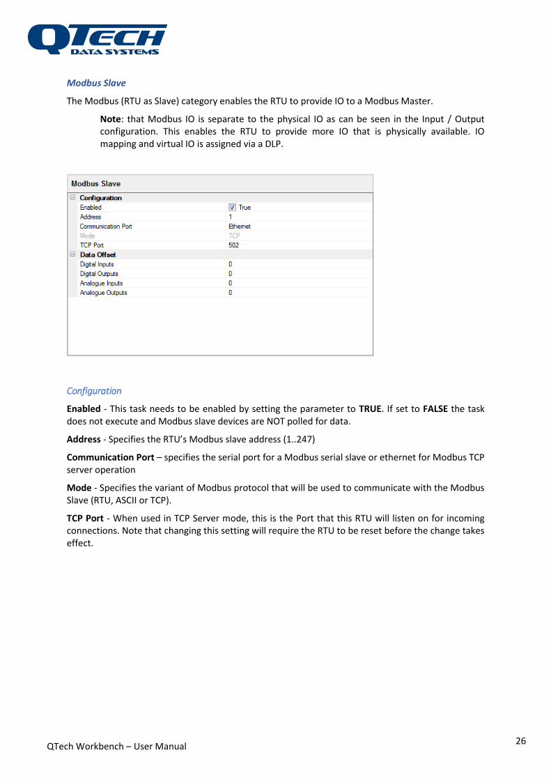
Adding Modules Expansion modules can be added by right clicking the Expansion Modules category. The following is a list of available modules and the additional IO that they can provide to the system:
Q23 - DATRAN excel Expansion module - 8 RDI, 8 RDO, 6 RAI, 2 RAO
Q26 - 16 RDI, 8 RDO
Configuring Module(x) Select each module on the Category tree and specify its Configuration parameters.
Configuration Name – specify a meaningful name for the module (friendly or mnemonic).
Address – this address should be unique on your serial network. This is automatically added by Workbench in numerical sequence, but it is an editable parameter. The expansion module will only respond to network packets that contain this destination address. Valid values are 1 to 239. Each module must have a unique address.
Telemetry Point Count Note: The expansion modules have a fixed range of IO. You cannot edit the Telemetry Point Count.
Telemetry point count for these modules is a read-only sub-category showing the number of physical inputs/outputs.
General Purpose I/O General purpose I/O modules define a range of virtual I/O - entries in the RTU data table that are not representative of real I/O.
Selecting the General Purpose I/O category presents a summary of the allocated GPIO:
Name is the label given to the module (“DI” etc.)
DI is the number of digital inputs allocated to this module
Range is the range of indexes spanned by the IO. The start is typically offset by other points of the same type, for example by the real, native digital inputs of the RTU (as seen in the image below)

QTech Workbench – User Manual
25
The table is similar for Digital Output [DO], Analogue Input [AI], Analogue Output [AO] and their ranges.
In the example configuration below, 4 GPIO blocks have been defined, named respectively “DI”, “DO” etc. From the summary page a total of 16 DI, 16 DO, 8 AI and 8 AO have been allocated by the 4 GPIO modules.
Configuring IO(x) Select each block on the Category tree and specify its Configuration parameters.
Configuration
Name – specify a meaningful name for the module (friendly or mnemonic). In the Category tree view “IO Block” (as a type tag) and the index is also appended to the Name.
Telemetry Point Count Specify the number of Digital and Analogue inputs and outputs (data point sets) which will be accessible upstream (to the DATRAN SCADA system).
QTech Workbench – User Manual
26
Modbus Slave
The Modbus (RTU as Slave) category enables the RTU to provide IO to a Modbus Master.
Note: that Modbus IO is separate to the physical IO as can be seen in the Input / Output configuration. This enables the RTU to provide more IO that is physically available. IO mapping and virtual IO is assigned via a DLP.
Configuration
Enabled - This task needs to be enabled by setting the parameter to TRUE. If set to FALSE the task does not execute and Modbus slave devices are NOT polled for data.
Address - Specifies the RTU’s Modbus slave address (1..247)
Communication Port – specifies the serial port for a Modbus serial slave or ethernet for Modbus TCP server operation
Mode - Specifies the variant of Modbus protocol that will be used to communicate with the Modbus Slave (RTU, ASCII or TCP).
TCP Port - When used in TCP Server mode, this is the Port that this RTU will listen on for incoming connections. Note that changing this setting will require the RTU to be reset before the change takes effect.

QTech Workbench – User Manual
27
Serial Port Settings
If the communication port for the slave is selected as a serial port then the baud rate settings for the port are displayed. Choose the Baud rate, Data bits, parity and stop bits required for communication to the Modbus master.
Data Offset
Normally a slave exposes all their IO upstream therefore allowing an external master to read and write all the data points. With the Modbus slave, it is possible to “protect” a given amount of data points (a number for each IO type as specified in the Data Offset table) from an external master.
For example, when there are two masters, a DATRAN Base Station (that uses QComms and has access to all data) and a Modbus master. While there is no problem if two masters read the same input, there is a conflict if they both try to independently set the same output. It’s not always feasible or easy to reconfigure the Modbus master. By setting the Modbus slave data to be offset in the RTU IO map above all the Real IO, the Modbus master won’t be able to access the points below the offset thus reserving them for DATRAN.
Modbus Master The Modbus (RTU as Master) option enables the RTU to poll and retrieve the IO from a Modbus Slave device.
Configuration
Enabled - This task needs to be enabled by setting the parameter to TRUE. If set to FALSE the task does not execute and Modbus slave devices are NOT polled for data.
QTech Workbench – User Manual
28
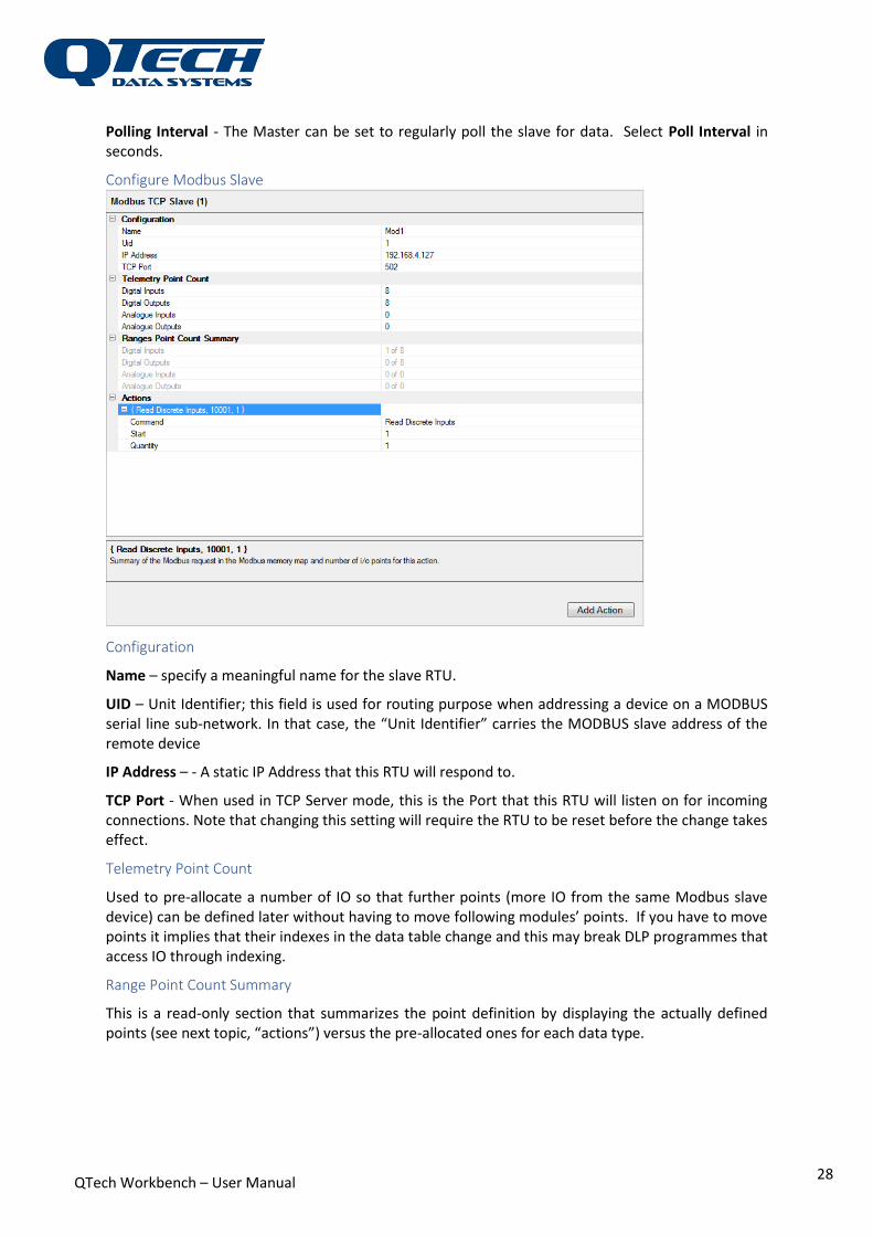
Polling Interval - The Master can be set to regularly poll the slave for data. Select Poll Interval in seconds.
Configure Modbus Slave
Configuration
Name – specify a meaningful name for the slave RTU.
UID – Unit Identifier; this field is used for routing purpose when addressing a device on a MODBUS serial line sub-network. In that case, the “Unit Identifier” carries the MODBUS slave address of the remote device
IP Address – - A static IP Address that this RTU will respond to.
TCP Port - When used in TCP Server mode, this is the Port that this RTU will listen on for incoming connections. Note that changing this setting will require the RTU to be reset before the change takes effect.
Telemetry Point Count
Used to pre-allocate a number of IO so that further points (more IO from the same Modbus slave device) can be defined later without having to move following modules’ points. If you have to move points it implies that their indexes in the data table change and this may break DLP programmes that access IO through indexing.
Range Point Count Summary
This is a read-only section that summarizes the point definition by displaying the actually defined points (see next topic, “actions”) versus the pre-allocated ones for each data type.

QTech Workbench – User Manual
29
Actions
The user can define Modbus request types to apply to the defined IO ranges. The Modbus entity number for the range is automatically calculated.
Multiple actions can be added to support Modbus requests to a remote Modbus slave. Each action is summarised in a row on the form. For example: Read Discrete Inputs, 10002,1 will allow RTU to read a discrete input bit mapped to address 10002 in the remote slave.
Two Modbus models for slave device data organisations are supported: separate blocks or in a single block. Separate blocks are accessed by the specific Modbus function (or request type) e.g. write coils will access one data block and read discrete inputs will access a different memory block.
In a single block model, the same data can be accessed via several Modbus functions.
Command – specifies a Modbus request type (read or write of inputs, coils or registers)
Start – defines the offset from the base to address the specific register (1 is the first register, a value of 0 is invalid).
Quantity – defines the number (range) of inputs or outputs to be read or modified.
Input / Output
Selecting the Input / Output category presents a summary of the allocated IO on the RTU:
Name is the label given to the module (“GenIO 1” etc.)
Type is the origin of the IO.
DI is the range of data point indices and the number of digital inputs allocated to this module. Similarly, for the Digital Output [DO], Analogue Input [AI], Analogue Output [AO].
In the example configuration below there are 8 external devices (as well as the native IO) connected to this RTU. There is a total of 72 DI, 72 DO, 60 AI and 12 AO have been allocated.
QTech Workbench – User Manual
30
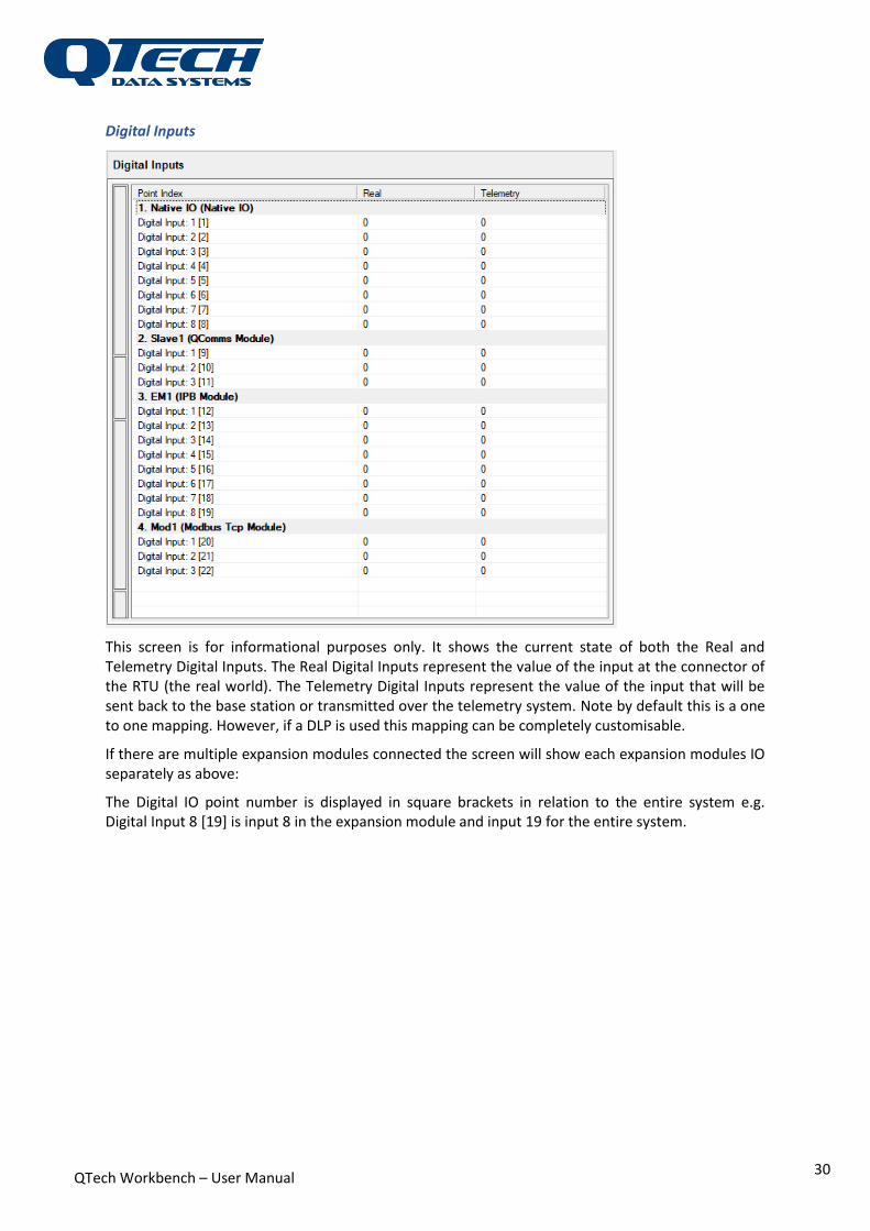
Digital Inputs
This screen is for informational purposes only. It shows the current state of both the Real and Telemetry Digital Inputs. The Real Digital Inputs represent the value of the input at the connector of the RTU (the real world). The Telemetry Digital Inputs represent the value of the input that will be sent back to the base station or transmitted over the telemetry system. Note by default this is a one to one mapping. However, if a DLP is used this mapping can be completely customisable.
If there are multiple expansion modules connected the screen will show each expansion modules IO separately as above:
The Digital IO point number is displayed in square brackets in relation to the entire system e.g. Digital Input 8 [19] is input 8 in the expansion module and input 19 for the entire system.
QTech Workbench – User Manual
31
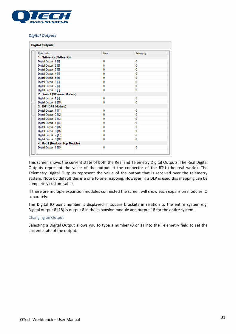
Digital Outputs
This screen shows the current state of both the Real and Telemetry Digital Outputs. The Real Digital Outputs represent the value of the output at the connector of the RTU (the real world). The Telemetry Digital Outputs represent the value of the output that is received over the telemetry system. Note by default this is a one to one mapping. However, if a DLP is used this mapping can be completely customisable.
If there are multiple expansion modules connected the screen will show each expansion modules IO separately.
The Digital IO point number is displayed in square brackets in relation to the entire system e.g. Digital output 8 [18] is output 8 in the expansion module and output 18 for the entire system.
Changing an Output
Selecting a Digital Output allows you to type a number (0 or 1) into the Telemetry field to set the current state of the output.

QTech Workbench – User Manual
32
Analogue Inputs
This screen is for informational purposes only. It shows the current state of both the Real and Telemetry Analogue Inputs. The Real Analogue Inputs represent the value of the input at the connector of the RTU (the real world). The Telemetry Analogue Inputs represent the value of the input that will be sent back to the base station or transmitted over the telemetry system. Note by default this is a one to one mapping. However if a DLP is used this mapping can be completely customisable.
If there are multiple expansion modules connected the screen will show each expansion modules IO separately as above:
The Analogue IO point number is displayed in square brackets in relation to the entire system e.g. Analogue Input 3 [10] is input 3 in the expansion module and input 10 for the entire system.

QTech Workbench – User Manual
33
Analogue Outputs
This screen shows the current state of both the Real and Telemetry Analogue Outputs. The Real Analogue Outputs represent the value of the output at the connector of the RTU (the real world). The Telemetry Analogue Outputs represent the value of the output that is received over the telemetry system. Note by default this is a one to one mapping. However, if a DLP is used this mapping can be completely customisable.
If there are multiple expansion modules connected the screen will show each expansion modules IO separately.
The Analogue IO point number is displayed in square brackets in relation to the entire system e.g. Analogue output 2 [4] is output 2 in the expansion module and output 4 for the entire system.
Changing an Output
Selecting an Analogue Output allows you to type a number (in the 0 - 65535 range) into the Telemetry field to set the current state of the output.
QTech Workbench – User Manual
34
RTU Input / Output
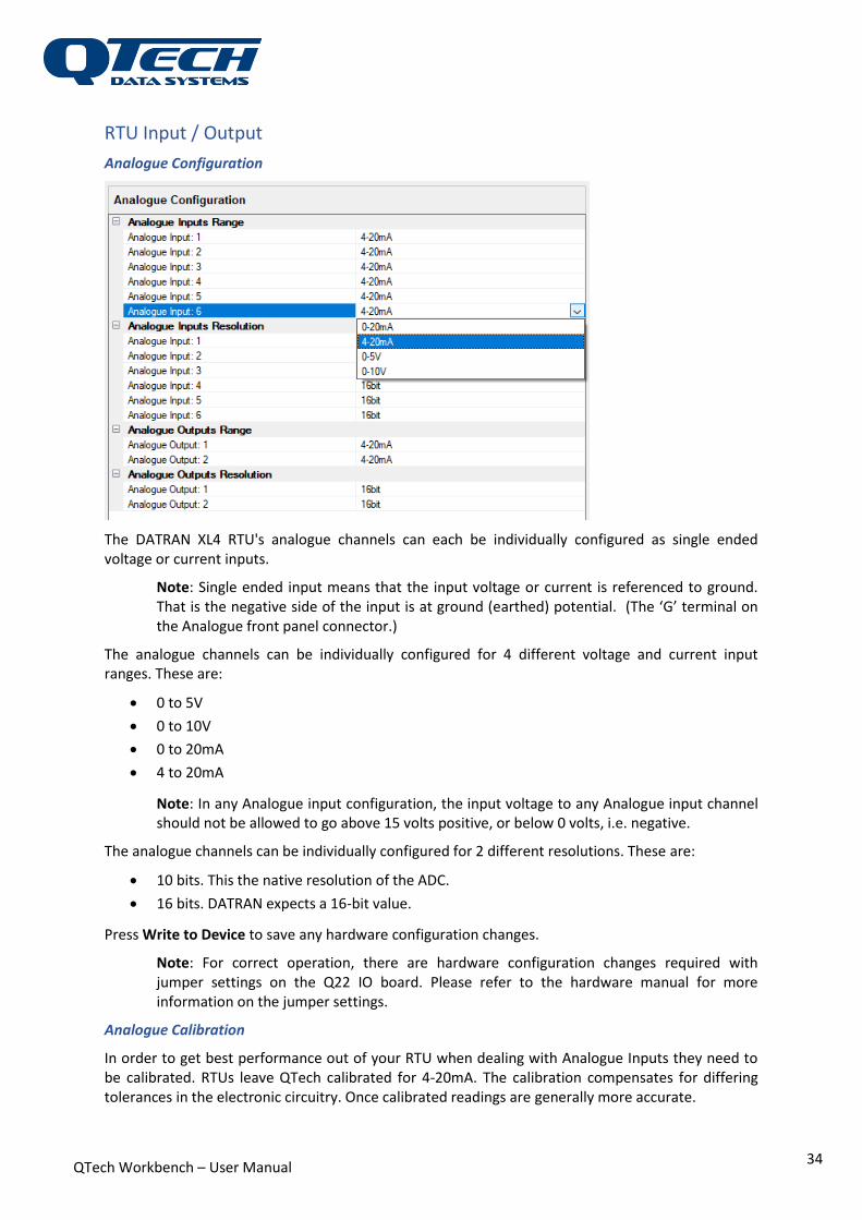
Analogue Configuration
The DATRAN XL4 RTU's analogue channels can each be individually configured as single ended voltage or current inputs.
Note: Single ended input means that the input voltage or current is referenced to ground. That is the negative side of the input is at ground (earthed) potential. (The ‘G’ terminal on the Analogue front panel connector.)
The analogue channels can be individually configured for 4 different voltage and current input ranges. These are:
0 to 5V
0 to 10V
0 to 20mA
4 to 20mA
Note: In any Analogue input configuration, the input voltage to any Analogue input channel should not be allowed to go above 15 volts positive, or below 0 volts, i.e. negative.
The analogue channels can be individually configured for 2 different resolutions. These are:
10 bits. This the native resolution of the ADC.
16 bits. DATRAN expects a 16-bit value.
Press Write to Device to save any hardware configuration changes.
Note: For correct operation, there are hardware configuration changes required with jumper settings on the Q22 IO board. Please refer to the hardware manual for more information on the jumper settings.
Analogue Calibration
In order to get best performance out of your RTU when dealing with Analogue Inputs they need to be calibrated. RTUs leave QTech calibrated for 4-20mA. The calibration compensates for differing tolerances in the electronic circuitry. Once calibrated readings are generally more accurate.

QTech Workbench – User Manual
35
IMPORTANT: calibration is performed at the factory and is not recommended for untrained personnel without specific calibration equipment. This section is provided for completeness only.
Input
Calibration of inputs requires a calibrated current source that can accurately supply 2mA and 18mA.
Clicking the “Read from RTU” button will retrieve the current calibration values from the RTU.
Note: The read values will overwrite the calibration values currently in Workbench.
During Calibration, these keys have the following action:
Enter: accepts the value and moves to the next point
Escape: restores the current value and moves to the next point
Down Arrow: restores the current value and moves to the next point (same as
Escape)
Up Arrow: restores the current value and moves to the previous point
To start the calibration process, click the Start Calibration button (only enabled when Workbench is connected to the RTU). The first available input will be focused.
For each Input select the Reading at 10% connect the 2mA (10%) source to the input. When the input settles then Save the value, or click Enter.
Select the Reading at 90% connect the 18mA (10%) source to the input. When the input settles then Save the value, or click Enter.
Do this for each input. When done write the calibration factors to the RTU by clicking the Write to RTU button.
QTech Workbench – User Manual
36
Note: Calibration values are specific to a given RTU while configuration can be applied to any RTU. The Write the RTU button sends the calibration values to the RTU. The Write to Device button sends the configuration to the RTU (no calibration values).
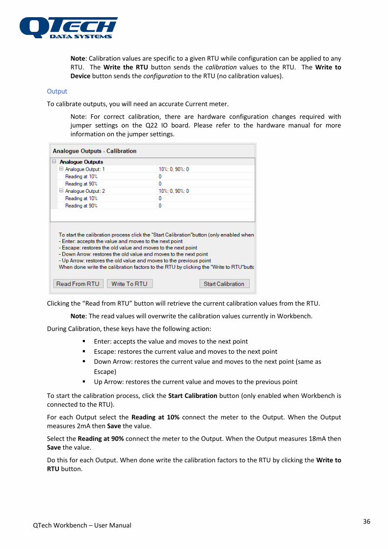
Output
To calibrate outputs, you will need an accurate Current meter.
Note: For correct calibration, there are hardware configuration changes required with jumper settings on the Q22 IO board. Please refer to the hardware manual for more information on the jumper settings.
Clicking the “Read from RTU” button will retrieve the current calibration values from the RTU.
Note: The read values will overwrite the calibration values currently in Workbench.
During Calibration, these keys have the following action:
Enter: accepts the value and moves to the next point
Escape: restores the current value and moves to the next point
Down Arrow: restores the current value and moves to the next point (same as
Escape)
Up Arrow: restores the current value and moves to the previous point
To start the calibration process, click the Start Calibration button (only enabled when Workbench is connected to the RTU).
For each Output select the Reading at 10% connect the meter to the Output. When the Output measures 2mA then Save the value.
Select the Reading at 90% connect the meter to the Output. When the Output measures 18mA then Save the value.
Do this for each Output. When done write the calibration factors to the RTU by clicking the Write to RTU button.
QTech Workbench – User Manual
37
Note: Calibration values are specific to a given RTU while configuration can be applied to any RTU. The Write the RTU button sends the calibration values to the RTU. The Write to Device button sends the configuration to the RTU (no calibration values).
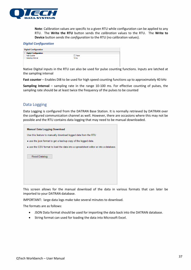
Digital Configuration
Native Digital inputs in the RTU can also be used for pulse counting functions. Inputs are latched at the sampling interval
Fast counter – Enables DI8 to be used for high speed counting functions up to approximately 40 kHz
Sampling Interval – sampling rate in the range 10-100 ms. For effective counting of pulses, the sampling rate should be at least twice the frequency of the pulses to be counted
Data Logging
Data Logging is configured from the DATRAN Base Station. It is normally retrieved by DATRAN over the configured communication channel as well. However, there are occasions where this may not be possible and the RTU contains data logging that may need to be manual downloaded.
This screen allows for the manual download of the data in various formats that can later be imported to your DATRAN database.
IMPORTANT: large data logs make take several minutes to download.
The formats are as follows:
JSON Data format should be used for importing the data back into the DATRAN database.
String format can used for loading the data into Microsoft Excel.

QTech Workbench – User Manual
38
Firmware Upload
This configuration tool provides a means of upgrading the firmware of your connected device. Updated firmware's will be released by QTech Data Systems from time to time and contain bug fixes and new features.
Firmware programming can be carried out in either online or offline mode. For devices with an old version of firmware that cannot be auto detected when pressing the Connect button (e.g. QDR v1.x) you must first select the device type from the Device Type menu.
Select the Firmware Upgrade category from the left hand side panel:
Press the Browse button to select the firmware as provided by QTech Data Systems.
Press the Program button to upgrade the firmware. The progress of the update will be shown during the reprogramming process.
Warning: Do not disconnect the device during the programming operation as this may render it inoperable.
Programming XL4
Before a firmware upgrade can be carried out on a DATRAN XL4 RTU you must ensure that the I.S.P. jumpers are installed as follows:
1. Remove the power from the XL4 by unplugging the power connector.
2. Remove the cover of the XL4 by unscrewing the 4 retaining screws on the bottom of the
case and carefully levering the case apart.
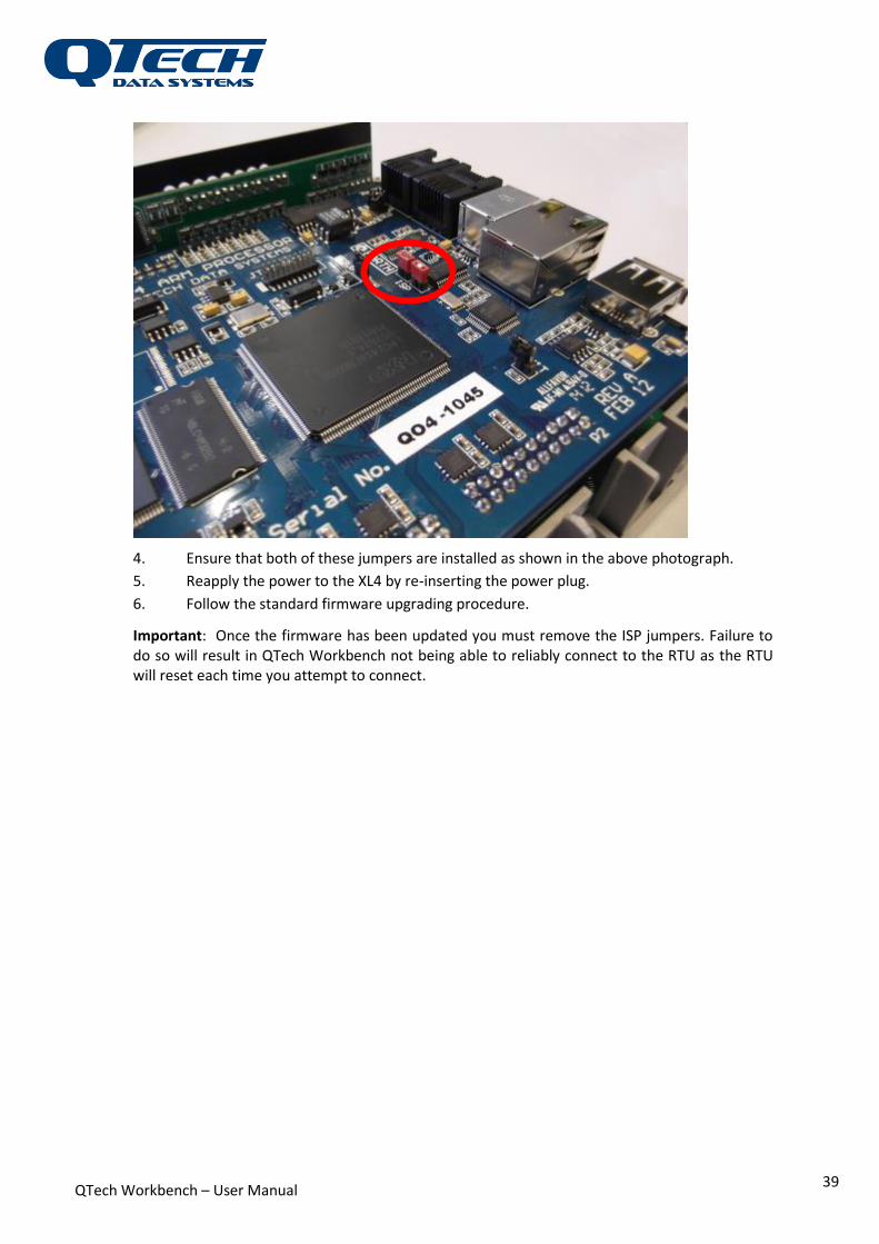
3. Locate the two Jumpers labelled I.S.P. behind the USB connector as shown in red in the
photograph below.
QTech Workbench – User Manual
39
4. Ensure that both of these jumpers are installed as shown in the above photograph.
5. Reapply the power to the XL4 by re-inserting the power plug.
6. Follow the standard firmware upgrading procedure.
Important: Once the firmware has been updated you must remove the ISP jumpers. Failure to do so will result in QTech Workbench not being able to reliably connect to the RTU as the RTU will reset each time you attempt to connect.
QTech Workbench – User Manual
40
Configuring the RTU - Workflow for a typical configuration
XL4 plus with Modbus & Dual Base Comms The DATRAN XL4 Plus can have many communication configurations. This application note covers a scenario whereby there is communication with the DATRAN base software by both an Ethernet connection to the Internet and a serial connection to a 3G modem.
Additionally, the Ethernet connection provides connectivity to a PLC via Modbus TCP. In this scenario, the XL4 Plus is a Modbus Client (Master).
All configuration is done with Workbench 2
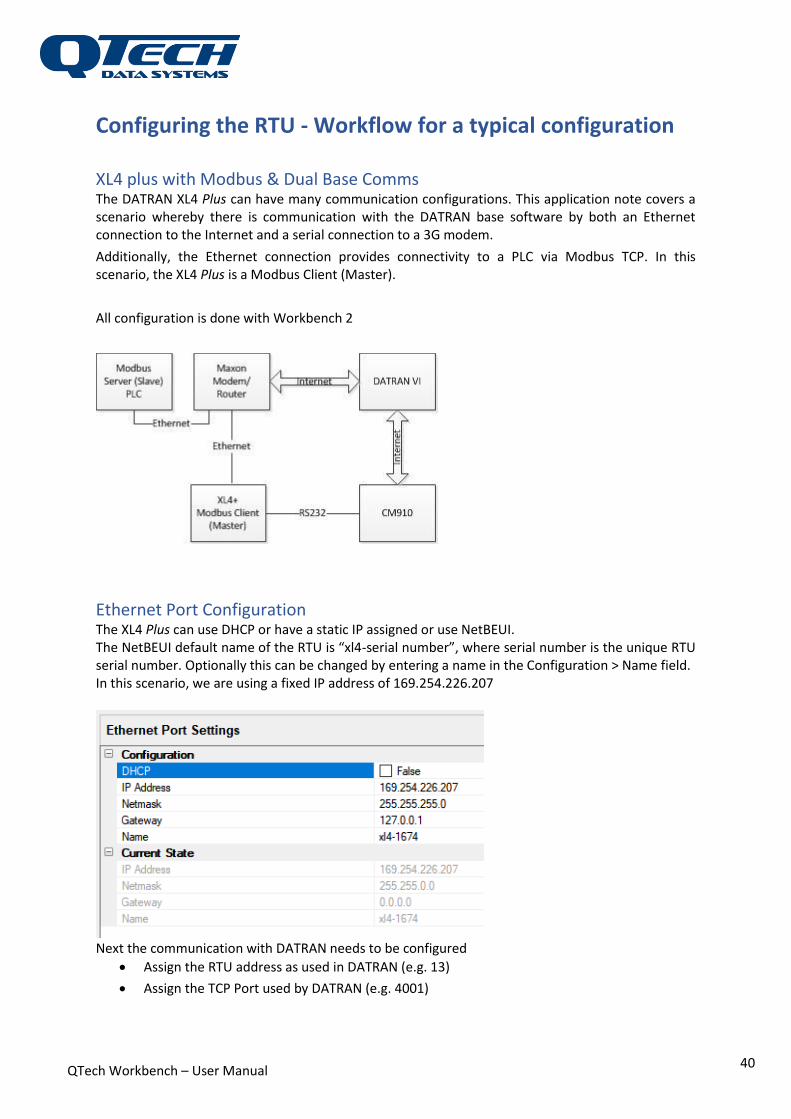
Ethernet Port Configuration The XL4 Plus can use DHCP or have a static IP assigned or use NetBEUI. The NetBEUI default name of the RTU is “xl4-serial number”, where serial number is the unique RTU serial number. Optionally this can be changed by entering a name in the Configuration > Name field. In this scenario, we are using a fixed IP address of 169.254.226.207
Next the communication with DATRAN needs to be configured
Assign the RTU address as used in DATRAN (e.g. 13)
Assign the TCP Port used by DATRAN (e.g. 4001)

QTech Workbench – User Manual
41
QTech Workbench – User Manual
42
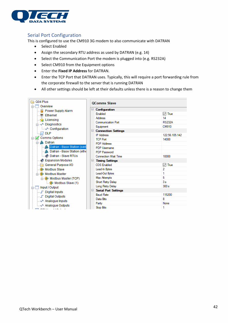
Serial Port Configuration This is configured to use the CM910 3G modem to also communicate with DATRAN
Select Enabled
Assign the secondary RTU address as used by DATRAN (e.g. 14)
Select the Communication Port the modem is plugged into (e.g. RS232A)
Select CM910 from the Equipment options
Enter the Fixed IP Address for DATRAN.
Enter the TCP Port that DATRAN uses. Typically, this will require a port forwarding rule from
the corporate firewall to the server that is running DATRAN
All other settings should be left at their defaults unless there is a reason to change them
QTech Workbench – User Manual
43
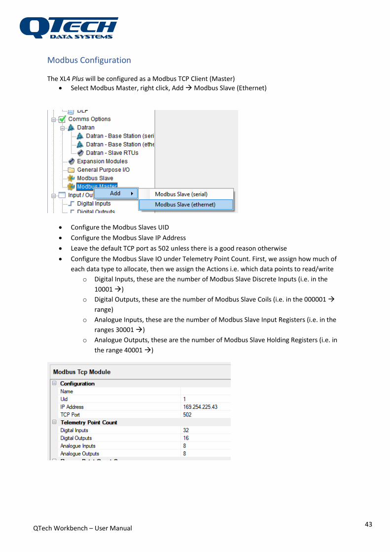
Modbus Configuration The XL4 Plus will be configured as a Modbus TCP Client (Master)
Select Modbus Master, right click, Add Modbus Slave (Ethernet)
Configure the Modbus Slaves UID
Configure the Modbus Slave IP Address
Leave the default TCP port as 502 unless there is a good reason otherwise
Configure the Modbus Slave IO under Telemetry Point Count. First, we assign how much of
each data type to allocate, then we assign the Actions i.e. which data points to read/write
o Digital Inputs, these are the number of Modbus Slave Discrete Inputs (i.e. in the
10001 )
o Digital Outputs, these are the number of Modbus Slave Coils (i.e. in the 000001
range)
o Analogue Inputs, these are the number of Modbus Slave Input Registers (i.e. in the
ranges 30001 )
o Analogue Outputs, these are the number of Modbus Slave Holding Registers (i.e. in
the range 40001 )

QTech Workbench – User Manual
44
Configure the Actions, which data we actually read/write. We assign it in blocks which do
not need to be contiguous.
o Click on Add Action, by default you get a Read Coils action. This can be changed by
clicking on the Command and selecting the action you require
o Select an Offset, this is the offset from the start of the Modbus range
o Select a Quantity, this is the number of contiguous values to read/write
Typical configuration is shown below. The XL4 Plus is
writing to the Modbus Slave coils addresses 00001 00016
reading from the Modbus Slave Discrete Inputs 10001 10008 and 10024 10025


