Quality Assurance in solar thermal heating and cooling technology Keeping track with recent and upcoming developments Summary report Stagnation temperature ÖFPZ Arsenal GmbH - Austrian Institute of Technology Franz Helminger, AIT, [email protected]Date of report: 30.05.2012 QAiST is supported by Intelligent Energy Europe Project IEE/08/593/SI2.529236 Deliverable D2.2 – R2.19
Transcript
Quality Assurance in solar thermal heating and cooling technology
Keeping track with recent and upcoming developments
Summary report Stagnation temperature
ÖFPZ Arsenal GmbH - Austrian Institute of Technology Franz Helminger, AIT, [email protected] Date of report: 30.05.2012
QAiST is supported by Intelligent Energy Europe Project IEE/08/593/SI2.529236 Deliverable D2.2 – R2.19
Summary report - R2.19- Stagnation temperature Page 2 of 12
Table of contents 1. INTRODUCTION................................................................................................................................... 3
2. STAGNATION TEMPERATURE IN EN12975:2006 .................................................................................. 3
2.1. Extrapolation according to Annex C............................................................................................ 4 2.2. Positioning of temperature sensor ............................................................................................. 4 2.3. Methods applying stagnation temperature ................................................................................ 5
3. ACTIVITIES AND MAIN RESULTS .......................................................................................................... 5
3.1. Comparison of methods .............................................................................................................. 5 3.2. Proposal for revision of EN 12975 ............................................................................................... 7 3.2.1. Text proposal for revision of EN 12975-1:2006 ........................................................................... 8 3.2.2. Text proposal for revision of EN 12975-2:2006 ........................................................................... 9
Project IEE/08/593/SI2.529236
Summary report - R2.19- Stagnation temperature Page 3 of 12
1. Introduction
Stagnation temperature is the temperature of a solar system in periods of time under no flow conditions. It is therefore the fluid temperature in a solar collector in periods of time where no useful energy is taken from solar collector and results from thegiven irradiance and ambient temperature. This temperature is taken into account when designing collectors, choosing collector materials (especially for insulation, absorber, diffusion barriers and reflectors) and designing solar systems (especially for heat transfer fluid, expansion tanks, safety valves and connecting equipment). During the process of collector mounting and connecting a collector to the rest of a solar system hot parts of the collector can cause personal injury. For this reasons the EN 12975-series requires that the stagnation temperature for an irradiance of 1000W/m² and an ambient temperature of 30°C is given by the manufacturer, at least on the collector label. Many manufacturers also include it in their installation manuals. The maximum temperature within a collector could be significantly higher than the normative stagnation temperature at fixed 1000 W/m² and 30°C ambient temperature.
2. Stagnation temperature in EN12975:2006
The method in EN 12975:2006 for determining the stagnation temperature is based on measuring the absorber temperature at the absorber sheet of flat plate collectors (FPC) or at the position with highest temperature for evacuated tubular collectors (ETC). This measurement must be done under following steady state conditions:
Irradiance 1000 W/m² ±10%
The measurement for determining the stagnation temperature is recommended in combination with high temperature resistance or exposure testing. If the combination with high temperature resistance is implemented following conditions are relevant:
Ambient temperature 20 – 40 °C
Wind speed < 1 m/s
If it is combined with exposure test the following conditions are crucial:
Irradiance > 850 W/m²
Ambient temperature > 10 °C
Wind speed -
Project IEE/08/593/SI2.529236
Summary report - R2.19- Stagnation temperature Page 4 of 12
In general the method for measuring the stagnation temperature at the absorber sheet is reliable for flat plate collectors (FPC). For other types of collectors other requirements should be taken into account, e.g. for heat pipe collectors the temperature at the header pipe is most likely the relevant temperature for system design and safety reasons. Also for collectors with active protection (e.g. concentrating tracking collectors) the highest temperature is not the stagnation temperature as described in EN 12975:2006.
2.1. Extrapolation according to Annex C
A method for extrapolation of the stagnation temperature is described in Annex C of EN 12975-2:2006. From the measurements in steady state conditions the stagnation temperature is extrapolated with the following equation:
amsm
m
sasStg tt
G
Gtt
Stgt Stagnation temperature for selected solar irradiance and ambient temperature
ast Selected ambient temperature
sG Selected solar irradiance
mG Measured solar irradiance
smt Measured absorber temperature
amt Measured surrounding air temperature
2.2. Positioning of temperature sensor
The positioning of a temperature sensor for measurements during the high temperature resistance test is described in the chapter 5.3.2 of EN 12975-2:2006. For the internal shock tests (see EN 12975-2:2006 chapter 5.6.2) and the external shock tests (see EN 12975-2:2006 chapter 5.5.2) the positioning for an optional temperature sensor is described in the same way as for high temperature resistance test. In chapter 5.2.2.2.1 of EN 12975-2:2006 a similar description is given for internal pressure test of organic absorbers. The most exact description of the positioning is given in chapter 5.3.2 (high temperature resistance test). There a recommendation for the positioning of a temperature sensor is given, but no detailed description of an exact positioning is given for evacuated tubular collectors. For concentrating collectors a description is missing in EN 12975-2:2006. In EN 12975-2:2006 – Annex A a number of figures (Figure A.2, Figure A.3, Figure A.4, Figure A.5, Figure A.6, Figure A.8 and Figure A.9) with temperature sensors are shown. These figures mainly show plain sheets as collectors.
Project IEE/08/593/SI2.529236
Summary report - R2.19- Stagnation temperature Page 5 of 12
2.3. Methods applying stagnation temperature
The internal pressure test for organic absorber is done at stagnation temperature. The conditions for this test are described in chapter 5.2.2.3 of EN 12975-2:2006. In chapter 5.2.2.3.1. following two options for calculating this temperature are given:
a. use measured collector performance characteristics b. extrapolate from average values, measured in the high-temperature resistance
test For option a. an instruction is missing in the EN 12975:2006. Option b. is done according to Annex C of EN 12975-2:2006
3. Activities and main results
The improvement of a method for determining the stagnation temperature was discussed in project meetings of QAiST and in a telephone conference. It was agreed to work out a comparison and an improved text for the revision of the EN 12975. The proposal should focus on requirements of planners and installers and show methods for all types of collectors.
3.1. Comparison of methods
A comparison between measured/extrapolated stagnation temperatures tStg (according to EN 12975:2006 Annex C; described in 2.1) and calculated stagnation temperatures out of performance characteristics tPC (according to EN 12975:2001 Annex C) is shown in Figure 1, Figure 2 and Figure 3. The values given at the x-axes are classes of:
PCStgtt
This comparison was done with data from Solar Keymark data sheets and from test institutes (IZES, TÜV and AIT). For data out of Solar Keymark data sheets it was taken into account that no data sheets were used with more than one collector on the data sheet. The reason for that was that according to Solar Keymark rules the durability and reliability tests shall be done at the largest collector of a product family and the performance test shall be done on the largest and the smallest collector of the product family. For this reason it could happen, that the performance figures are given from a collector with another size than the tested collector for stagnation temperature. Furthermore it was considered that performance tests are carried out under wind speed between 2 and 4 m/s. Figure 1 shows the result of the comparison for flat plate collectors (FPC). For this type of collector both methods seem to fit very well. 59 FPC´s were taken into account and the width of the temperature classes was 10 K.
Project IEE/08/593/SI2.529236
Summary report - R2.19- Stagnation temperature Page 6 of 12
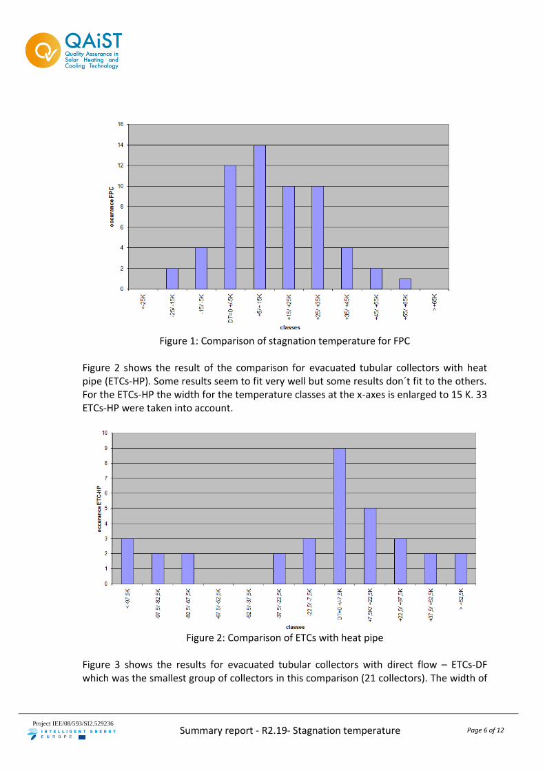
Figure 1: Comparison of stagnation temperature for FPC
Figure 2 shows the result of the comparison for evacuated tubular collectors with heat pipe (ETCs-HP). Some results seem to fit very well but some results don´t fit to the others. For the ETCs-HP the width for the temperature classes at the x-axes is enlarged to 15 K. 33 ETCs-HP were taken into account.
Figure 2: Comparison of ETCs with heat pipe
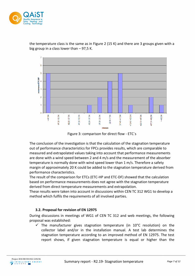
Figure 3 shows the results for evacuated tubular collectors with direct flow – ETCs-DF which was the smallest group of collectors in this comparison (21 collectors). The width of
Project IEE/08/593/SI2.529236
Summary report - R2.19- Stagnation temperature Page 7 of 12
the temperature class is the same as in Figure 2 (15 K) and there are 3 groups given with a big group in a class lower than – 97,5 K.
Figure 3: comparison for direct flow - ETC´s
The conclusion of the investigation is that the calculation of the stagnation temperature out of performance characteristics for FPCs provides results, which are comparable to measured and extrapolated values taking into account that performance measurements are done with a wind speed between 2 and 4 m/s and the measurement of the absorber temperature is normally done with wind speed lower than 1 m/s. Therefore a safety margin of approximately 20 K could be added to the stagnation temperature derived from performance characteristics. The result of the comparison for ETCs (ETC-HP and ETC-DF) showed that the calculation based on performance measurements does not agree with the stagnation temperature derived from direct temperature measurements and extrapolation. These results were taken into account in discussions within CEN TC 312 WG1 to develop a method which fulfils the requirements of all involved parties.
3.2. Proposal for revision of EN 12975
During discussions in meetings of WG1 of CEN TC 312 and web meetings, the following proposal was established: The manufacturer gives stagnation temperature (in 10°C resolution) on the
collector label and/or in the installation manual. A test lab determines the stagnation temperature according to an improved method of EN 12975. The test report shows, if given stagnation temperature is equal or higher than the
Project IEE/08/593/SI2.529236
Summary report - R2.19- Stagnation temperature Page 8 of 12
determined stagnation temperature. The method of determination is also given by the test lab.
Based on this, the following draft for revision of the EN 12975 was developed.
3.2.1. Text proposal for revision of EN 12975-1:2006
6 Safety The maximum fluid temperature to be considered in the design of a solar collector or solar plant is the collector stagnation temperature. Materials to be used in the manufacture of collectors or installations incorporating the collector (expansion tanks, safety valves, etc.) shall be chosen taking into account this temperature. The stagnation temperature shall be calculated in accordance with Annex C of EN 12975-2 under the following climate parameters: - Hemispherical irradiance on collector plane 1000 W/m²; - Surrounding air temperature 30 ºC. Stagnation temperature (see Annex C EN 12975-2) may be combined with the high temperature resistance or exposure test. The collector shall provide for safe installation and mounting. Sharp edges, loose connections and other potentially dangerous features shall be avoided. If the weight of the empty collector exceeds 60 kg, an anchorage for a lifting device shall be included, except for the collectors that are assembled on the roof. Collectors filled with a heat transfer fluid irritant to human skin or eyes, or toxic shall carry a warning label. 7.2 LABELING Collectors shall carry a visible and durable label with the following data: - Name of manufacturer; - Type; - Serial number; - Year of production; - Gross area of collector; - Dimensions of collector - Maximum operation pressure; - Stagnation temperature; - Volume of heat transfer fluid;
Project IEE/08/593/SI2.529236
Summary report - R2.19- Stagnation temperature Page 9 of 12
- Weight of empty collector; Made in:.............. 7.3 Installer instruction manual Solar collectors shall be accompanied by an installer instruction manual, if traded as stand-alone components. When they are part of a complete system, the system installation manual can cover the complete system. In that case no separate manual for the collector shall be required. The instruction manual shall at least contain the following information: - dimensions and weight of the collector, instructions about the transport and handling
of the collector; stagnation temperature of the collector - description of the mounting procedure; - recommendations about lightning protection; - instructions about the coupling of the collectors to one another and the connection of
the collector field to the heat transfer circuit, including dimensions of pipe connections for collector arrays up to 20 m²;
- recommendations about the heat transfer media which may be used (also with respect to corrosion) and precautions to be taken during filling, operation and service;
- the maximum operation pressure, the pressure drop and the maximum and minimum tilt angle;
- permissible wind and snow load - maintenance requirements. If the collector is traded as a component and sold directly to customers, all relevant documentation concerning personal safety, maintenance and handling of the product shall be made available to the customer in the national language of which country is sold. NOTE: The stagnation temperature shown at the collector label and in installer instruction manual should be given in 10°C resolution.
3.2.2. Text proposal for revision of EN 12975-2:2006
5.2.2.3 Test conditions 5.2.2.3.1 Temperature For absorbers made of organic materials, the test temperature shall be the maximum temperature which the absorber will reach under stagnation conditions (see Annex C). Annex B (normative) Durability and reliability test report sheets B.3.1.3 Determined collector stagnation temperature: ................................................. °C
Project IEE/08/593/SI2.529236
Summary report - R2.19- Stagnation temperature Page 10 of 12
Provide details of calculation, showing input data used (attach separate page if necessary)
B.X Stagnation temperature B.X.1 Method used for determination of stagnation temperature
o Calculation out of performance characteristics o Measurement and extrapolation
B.X.2 Positioning of temperature sensor (just for evacuated tubular collectors) B.X.3 Test result
o Stagnation temperature is given correct by manufacturer Annex C (normative) Stagnation temperature of liquid heating collectors C.1 General This Annex provides methods for determining the stagnation temperature of a collector, i.e. the temperature of the collector during periods of no useful heat removal from the collector with high solar radiation and ambient surrounding temperatures. These methods are used to check, that stagnation temperature at collector label and in installer instruction manual is higher than determined stagnation temperature. The stagnation temperature should be determined for a selected solar irradiance Gs and a selected ambient temperature tas. The determined stagnation temperature is used for following tests: - the internal pressure testing of collectors with organic absorbers (see 5.2.2); - the high-temperature resistance test using a hot fluid loop (see 5.3). For different kind of collectors different methods for determination of stagnation temperature are appropriate. Table C.1 gives an overview:
Collector type Clause C.2 Clause C.3
Flat plate collector Inorganic absorber X X
Organic absorber X X
Evacuated tube collector Heat pipe X
Direct flow X
C.2 Measurement and extrapolation of stagnation temperature
Project IEE/08/593/SI2.529236
Summary report - R2.19- Stagnation temperature Page 11 of 12
The stagnation temperature tstg, for the selected values of solar irradiance Gs and ambient temperature tas, is calculated by extrapolating from measured steady-state values of: - solar irradiance Gm (natural or simulated) on the collector plane; - surrounding air temperature tam; - absorber temperature tsm. while the collector is exposed to the available solar irradiance and ambient temperature (outdoors, or in a solar irradiance simulator) under steady-state conditions without heat extraction from the collector (stagnation conditions). The expression for determining the stagnation temperature for the selected parameters (Gs and tas) is:
)t(tG
Gtt amsm
m
sasstg
(C.1)
It is based on the approximation that the ratio (tsm - tam)/Gm remains constant under steady-state collector stagnation conditions. This approximation is acceptable only if the irradiance level (Gm) used during the test is within 10 % of the irradiance specified for the stagnation conditions (Gs). NOTE: For flat plate collectors the temperature sensor shall be positioned at two-thirds of the absorber height and half the absorber width. It shall be fixed firmly in a position to ensure good thermal contact with the absorber. The sensor shall be shielded from solar radiation. NOTE: For evacuated tubular collectors the temperature sensor should be placed at a suitable location in the collector, and this location should be clearly described with the test results. C.3 Determining stagnation temperature using efficiency parameters The thermal performance of the liquid heating collector can be used to calculate its stagnation temperature. The thermal performance must either be known or be determined by testing the collector accordingly. The second-order equation (C.2) for the instantaneous thermal efficiency of the collector should be used for determining the stagnation temperature: 2*
2
*
10 mm TGaTa (C.2)
The instantaneous efficiency is based either on the aperture area Aa or on the absorber
area AA. Two different sets of constants 0, a1 and a2 may be available to express the instantaneous efficiency of the collector. The stagnation temperature for the selected irradiance Gs and ambient temperature tas is calculated by the following equation:
Project IEE/08/593/SI2.529236
Summary report - R2.19- Stagnation temperature Page 12 of 12
C
a
Gaaatt s
asstg
202
4
2
21
20
2
11 (C.3)
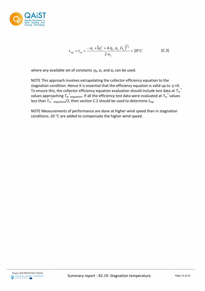
where any available set of constants 0, a1 and a2 can be used. NOTE This approach involves extrapolating the collector efficiency equation to the
stagnation condition. Hence it is essential that the efficiency equation is valid up to ≈0. To ensure this, the collector efficiency equation evaluation should include test data at Tm
*
values approaching Tm*
stagnation. If all the efficiency test data were evaluated at Tm* values
less than Tm* stagnation/2, then section C.2 should be used to determine tstg.
NOTE Measurements of performance are done at higher wind speed than in stagnation conditions. 20 °C are added to compensate the higher wind speed.