QUALITY ASSURANCE PROJECT PLAN (QAPP) FOR AIR SAMPLING ACTIVITIES AT THE BRIDGETON SANITARY LANDFILL IN BRIDGETON, MISSOURI Prepared for: Missouri Department of Natural Resources 1730 East Elm Street Jefferson City, Missouri 65102 Prepared by: Soil Water Air Protection Enterprise 1640 Fifth Street, Suite 204 Santa Monica, CA 90401 April 2013
Transcript
QUALITY ASSURANCE PROJECT PLAN (QAPP)
FOR AIR SAMPLING ACTIVITIES AT THE
BRIDGETON SANITARY LANDFILL
IN BRIDGETON, MISSOURI
Prepared for: Missouri Department of Natural Resources
1730 East Elm Street Jefferson City, Missouri 65102
Prepared by: Soil Water Air Protection Enterprise
1640 Fifth Street, Suite 204 Santa Monica, CA 90401
Paul Rosenfeld, Ph.D. - Project Manager ...................................................................... 1 John Blank - Local Field Services Manager .................................................................. 2 Dan Norris - MDNR Coordinator .................................................................................. 2
2. SITE DESCRIPTION ....................................................................... 3
3. OVERVIEW OF SAMPLING ACTIVITIES ....................................... 4
3.1. Sampling Locations .................................................................................................... 4 3.2. Data Quality Objectives .............................................................................................. 5 3.3. Health and Safety Plan Implementation .................................................................... 5
4. AIR MONITORING AND SAMPLING APPROACH ........................ 6
4.1. Air Monitoring Procedures ......................................................................................... 6 Odor Monitoring Using Nasal Ranger ........................................................................... 6 Benzene Monitoring Using UltraRAE 3000 ................................................................... 7 H2S Monitoring Using Jerome Analyzer ....................................................................... 8
carbon monoxide, and carbon dioxide). Additional air sampling activities have been conducted
at and in the area of the Site by the MDNR.2 These sampling activities have indicated that VOCs,
aldehydes, reduced sulfur compounds, hydrogen sulfide ("H2S"), and other contaminants have
been present in ambient air at elevated concentrations. The results of previous air quality
sampling indicates that VOCs, acetaldehyde, dimethyl sulfide, H2S, and other contaminants are
present in the ambient air at low parts per billion ("ppb") range.
A summary of previous environmental investigations of the Site, including sampling of landfill
gas from several locations under the landfill flexible membrane liner ("FML") and ambient air
samples from onsite and off-site locations is presented in the project SAP and project HASP.
Project Personnel may be exposed to low ambient air concentrations of contaminants in the
ranges detected during previous sampling events. Project Personnel will reference the project
HASP that has been developed specifically for the planned air monitoring and sampling activities.
1 Overview of Bridgeton Sanitary Landfill - West Lake Landfill, website page. Missouri Department of Natural Resources >> Division of Environmental Quality. Accessed on April 4, 2013. 2 Air Sampling - Bridgeton Sanitary Landfill, website page. Missouri Department of Natural Resources >> Solid Waste Management Program. Accessed on April 4, 2013.
4
3. OVERVIEW OF SAMPLING ACTIVITIES
Air monitoring activities will consist of field evaluations to measure air quality around the Site
using direct-reading instruments. Air sampling activities will consist of the collection of samples
of air using specific sampling procedures, equipment, and laboratory analytical testing of air
samples. The planned activities can be divided into several categories of routine air monitoring
and sampling tasks. These activities will consist of Daily Monitoring Events, Weekly Sampling
Events, Immediate Sampling Events, and Comprehensive Sampling Events. The parameters to be
monitored and/or sampled will vary for each type of sampling event. These various air
monitoring and air sampling events are discussed in the project SAP document.
Daily Sampling Events will consist of air monitoring measurements using direct-reading
instruments. Air monitoring measurements will include screening surveys for odors, VOCs (i.e.,
benzene), and H2S. The monitoring equipment that will be used for air quality screening during
Daily Sampling Events is discussed below. MDNR may coordinate with the landfill operator to
conduct some on-site ambient air monitoring as part of Daily Sampling Events.
Weekly and Immediate Sampling Events will include the collection of air samples for analysis of
aldehydes, VOCs, and reduced sulfur compounds. Weekly Events will be conducted
approximately every six (6) days or as determined by MDNR staff. Immediate Sampling Events
are anticipated to be conducted infrequently. Immediate Sampling will be coordinated by MDNR
and may coincide with landfill construction activities. The first Comprehensive Sampling Event
will include analyses of air samples for: aldehydes, amines, ammonia, carboxylic acids, hydrogen
reduced sulfur compounds, and fixed gases. In addition, air samples will also be collected for
odor evaluation. The sampling equipment that will be used for air quality sampling events is
discussed below.
3.1. SAMPLING LOCATIONS
Air monitoring will be conducted using a route map that will be developed with input from
MDNR and based on the results of one or more initial Daily Monitoring Events. The routes that
will be followed during the course of a typical air monitoring event will consist of public
highways, streets, access roads, and other thoroughfares that connect monitoring station locations
in a linear fashion. Sampling locations for Weekly and Immediate Sampling Events will be
determined by MDNR staff using information obtained from the MDNR meteorological station
and other information. Sampling locations for Comprehensive Sampling Events will also be
determined based on consultation MDNR and other factors. The locations of air samples at the
Bridgeton Sanitary Landfill with be determined based on coordination with the landfill operator.
MDNR will coordinate all on-site sampling.
5
3.2. DATA QUALITY OBJECTIVES
The objective of air monitoring and sampling will be to determine the presence of VOCs, H2S
and other chemical compounds (listed above in Section 4.1) in ambient air resulting from
emissions at the Site. The data to be collected will be used by MDNR to characterize the
chemical properties of the air samples and to characterize potential exposures of members of the
public to constituents potentially related to emissions from the Site by reporting on chemical
constituents specifically found in the environment at the time and location of sample collection.
The data may also be used by MDNR to make informed decisions related to appropriate
protective actions necessary to ensure health and safety of members of the community. The data
will also be used to evaluate the chemicals responsible for malodors that have been observed in
the surrounding community. Previous air quality sampling suggests that some VOCs,
acetaldehyde, dimethyl sulfide, H2S, and possibly other contaminants are associated with odors
generated by the landfill gas emissions.
3.3. HEALTH AND SAFETY PLAN IMPLEMENTATION
A project Health and Safety Plan (HASP) has been developed to address health and safety issues
relating to site-specific hazards that have been identified for the proposed air quality monitoring
and sampling activities. The project HASP discusses hazards such as slips, trips, and falls; heat
and cold stress; vehicle traffic hazards; air monitoring; personal protective equipment;
decontamination; and other safety and health issues applicable to the proposed sampling
activities. All Project Personnel are required to adhere to the HASP while conducting air
monitoring and sampling activities.
6
4. AIR MONITORING AND SAMPLING APPROACH
Air monitoring and sampling will be conducted in general accordance with the United States
Environmental Protection Agency ("U.S. EPA") guidelines and standard industry practices. As
explained above in Section 3.1, Project Personnel will perform air monitoring activities during
Daily Monitoring Events and air sampling activities during Weekly, Immediate, and
Comprehensive Sampling Events. The methods and procedures that will be followed for these
sampling activities is described below.
4.1. AIR MONITORING PROCEDURES
Real-time air monitoring will be performed at off-site locations surrounding the Site. Air
monitoring will be conducted by a subcontractor to SWAPE using direct-reading instruments.
Various instruments will be utilized to monitor ambient air levels of odors, VOCs (i.e., benzene),
and H2S. A general description of the air monitoring activities and methods is presented in the
project SAP document. The SAP also includes specification sheets for various monitoring and
sampling equipment. This QAPP provides additional details concerning the sampling
methodology and procedures.
During the course of a typical air monitoring event, Project Personnel will document their
activities on various project field forms that will be utilized throughout the course of the project.
Project Personnel will document daily work activities, the results of monitoring instrument
calibration(s), observations during air monitoring events, monitoring locations and readings from
direct-reading instruments, and any other information, as necessary. Field forms that will be used
during the course of this project are presented in Attachment A.
Air monitoring instruments that require pre-sampling calibration will be calibrated prior to use
each day of Daily Monitoring Event(s). Instrument calibrations will be recorded on a standard
calibration log. Some air monitoring instruments that will be used by Project Personnel do not
require any calibration or only require calibration periodically (by the manufacturer).
Information regarding instrument calibration is presented below for the instruments that require
daily calibration. If other monitoring instruments are utilized during the course of the project,
then appropriate calibration routines will be adopted based on the respective manufacturer's
recommended practices. Additional monitoring instruments will be addressed in addenda to this
QAPP document.
Odor Monitoring Using Nasal Ranger
Odors will be monitored using a Nasal Ranger® Field Olfactometer ("Nasal Ranger"). The Nasal
Ranger is a hand-held field olfactometer used for measuring and quantifying odor strength in the
ambient air. Project Personnel will measure and record odors in the community by estimating the
7
Dilution-to-Threshold ("D/T") ratio associated with odor observations at monitoring locations.
Odor monitoring will be performed in general accordance with the procedures specified in the
manufacturer's operation manual (see portion in Attachment B). A complete copy of the
operation manual will be distributed to Project Personnel. The basic procedures for collecting
odor measurements are as follows:
• Refer to Test Procedure Flow Chart in the Nasal Ranger Operation Manual (page 5).
• Record the current monitoring location on the Ambient Air Monitoring Data Collection Sheet (include map ID and/or GPS coordinates).
• Place a Nasal Mask on the unit, turn on the Nasal Ranger and Start nasal breathing using the appropriate start settings (with D/T Dial set to BLANK position).
• Follow the Test Procedure Flow Chart through the D/T dial steps to identify when an ODOR is first perceived. When an ODOR is perceived, note the D/T range indicated on the Test Procedure Flow Chart.
• Record the D/T range on the Ambient Air Monitoring Data Collection Sheet.
• Also record any characteristics associated with the ODOR, such as "rotten cabbage" or other qualifying observations.
Carbon filters for the Nasal Ranger instrument will be changed out approximately every month.
Benzene Monitoring Using UltraRAE 3000
Air monitoring for benzene will be performed using an UltraRAE 3000 photo-ionization detector
("PID"). The UltraRAE 3000 has a sensor range for monitoring benzene from 0 to 200 parts per
million ("ppm") with a resolution of 0.05 ppm. PID monitoring with the UltraRAE will be
performed in general accordance with the procedures specified in the manufacturer's operation
manual (see see portion in Attachment C). A complete copy of the operation manual will be
distributed to Project Personnel. The basic procedures for collecting PID measurements are as
follows:
• IMPORTANT. Calibrate instrument in accordance with manufacturer's operation manual before each day's use (see CALIBRATION instructions below).
• Refer to Operating the Instrument section in the Operation Manual (page 23).
• Record the current monitoring location on the Ambient Air Monitoring Data Collection Sheet (include map ID and/or GPS coordinates).
• Turn unit power button ON (press and hold MODE button). When the display turns on, release the [MODE] key.
• Do not perform a zero calibration, press the MODE key when prompted to bypass zero calibration.
• Begin recording PID readings at the monitoring location.
8
• Record the instrument reading (ppm value) on the Ambient Air Monitoring Data Collection Sheet.
CALIBRATION of the UltraRAE 3000 using a two-point or three-point calibration should be
conducted prior to sampling. The two-point calibration should be sufficient for conducting the
ambient monitoring for this project. The basic procedures for two-point calibration are as follows
(see Attachment D):
• Refer to Standard Two-Point Calibration (Zero & Span) section in the Operation Manual (page 49).
• Turn unit power button ON (press and hold MODE button). When the display turns on, release the [MODE] key.
• Press and hold [MODE] and [N/-] until you see the Password screen, press [MODE] key gain to enter Calibration screen.
• Conduct a Zero calibration (page 51) and document the calibration record and results on a Calibration & Post Monitoring Check Log.
• Conduct a Span calibration (page 52) and document the calibration record and results on a Calibration & Post Monitoring Check Log.
Following the completion of air monitoring activities, a CALIBRATION CHECK may be
performed using the above Zero and Span gases used for calibration. To conduct a calibration
check, connect the instrument to the zero gas and/or span gas and record the resultant instrument
reading on the Calibration & Post Monitoring Check Log. The calibration check is useful for
tracking the performance of the instrument from pre-monitoring calibration through the
completion of a screening survey.
The benzene-specific gas separation tube(s) used for monitoring with the UltraRAE 3000 will be
changed out in accordance with the manufacturer's recommendations. The colorimetric gas tubes
show a color band that indicates the adsorption of VOCs; therefore, the air monitoring contractor
will determine the change out of tube(s) based on regular instrument inspection and maintenance.
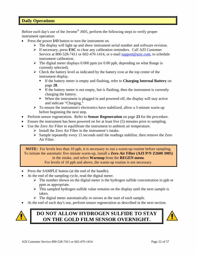
H2S Monitoring Using Jerome Analyzer
Air monitoring for H2S will be performed using a Jerome J605 Gold Film H2S Analyzer
(manufactured by Arizona Instruments LLC). The Jerome J605 instrument has a sensor range for
monitoring H2S from 3 ppb to 10 ppm with a resolution of 0.02 ppb. H2S monitoring with the
Jerome J605 Analyzer will be performed in general accordance with the procedures specified in
the manufacturer's operation manual (see see portion in Attachment E). A complete copy of the
operation manual will be distributed to Project Personnel. The basic procedures for collecting
H2S measurements are as follows:
9
• Refer to the Unpacking the Instrument (page 4) and Instrument Operation (page 15) sections in the User Manual.
• IMPORTANT. Perform a sensor regeneration (see pages 5 and 23 of User Manual). The regeneration process takes 45 minutes and should be done before each day's use.
• Record the current monitoring location on the Ambient Air Monitoring Data Collection Sheet (include map ID and/or GPS coordinates).
• Turn unit power button ON (press and hold I/O button). Ensure the unit has been powered on for at least five (5) minutes prior to sampling.
• Begin recording H2S readings at the monitoring location.
• Record the instrument reading (ppm value) on the Ambient Air Monitoring Data Collection Sheet.
4.2. AIR SAMPLING PROCEDURES
For Weekly and Immediate Sampling Events, Project Personnel will deploy sampling stations at
approximately four (4) off-site locations in the community surrounding the Site. The parameters
and laboratory methods for the Weekly and Immediate Sampling Events is presented in Table 1.
Samples collected during these events will be analyzed for aldehydes, VOCs, and reduced sulfur
compounds. As requested by MDNR, Project Personnel could mobilize on-site for collection of
air samples using the same sampling equipment.
For Comprehensive Sampling Events, Project Personnel will deploy sampling stations at
approximately six (6) off-site locations in the community surrounding the Site, as well as two (2)
locations on-site to sample ambient air. Three (3) additional samples are planned to be collected
from the landfill gas source under the FML. The parameters and associated laboratory analytical
testing methods that will be included in the sampling program for the Comprehensive Sampling
Event(s) is presented in Table 1.
During the course of a typical air monitoring event, Project Personnel will document their
activities on various project field forms that will be utilized throughout the course of the project.
Project Personnel will document daily work activities, the results of sampling equipment
calibration(s), observations during air sampling events, air monitoring and air sampling locations
and readings from direct-reading instruments, and any other information, as necessary. Field
forms that will be used during the course of this project are presented in Attachment A.
Summa Canister Sampling
Air samples to be analyzed for VOCs, reduced sulfur compounds and fixed gases will be
collected at each location using a laboratory-supplied Summa® Canister. Each Summa®
Canister used for ambient air sampling will be cleaned and laboratory-certified and shipped with
10
a flow controller set to sample air over a period of four (4) hours. Summa® Canister flow
restrictors are calibrated by the analytical laboratory. Summa® Canister sampling will be
performed in general accordance with the procedures indicated in Attachment F. The basic
procedures for collecting Summa® Canister samples are as follows:
• Record the current sampling location on the appropriate field forms (include map ID and/or GPS coordinates). GPS coordinates will be determined using MDNR equipment.
• For ambient samples, place flow controller on a certified Summa® Canister and tighten fitting. For landfill gas samples, place hose barb assembly onto a specified landfill gas sampling canister and tighten fitting (connect tubing as needed to sample port).
• Initiate sampling by turning the canister flow valve turncock open.
• Check the gauge and record the vacuum gauge reading, date, and start time onto the appropriate field forms (e.g., Daily Field Activities Log, Chain of Custody).
• Record start time, date and initial reading of the gauge on the tag and COC supplied with Summa® Canister.
• Check the progress of sampling event approximately every 30 minutes to make sure the canister is sampling properly.
• IMPORTANT. The sampling should be stopped when the gauge reads -5 (inHg), or after the predetermined time of 4 hours, whichever occurs first. To stop sampling, close the canister flow control valve.
• Record the final vacuum gauge reading and end time onto the appropriate field forms (e.g., Daily Field Activities Log, Chain of Custody).
NOTE that laboratory certified Summa® Canisters will be used for ambient air sampling.
However, other Summa® Canisters will be dedicated for use for sampling landfill source gas.
DO NOT USE certified clean Summa® Canisters for sampling source gas. As indicated above,
Summa® Canister flow restrictors are calibrated by the analytical laboratory. therefore, no
calibration is necessary. Flow restrictors will be calibrated and shipped individually with
Summa® Canisters supplied by the analytical laboratory for this project.
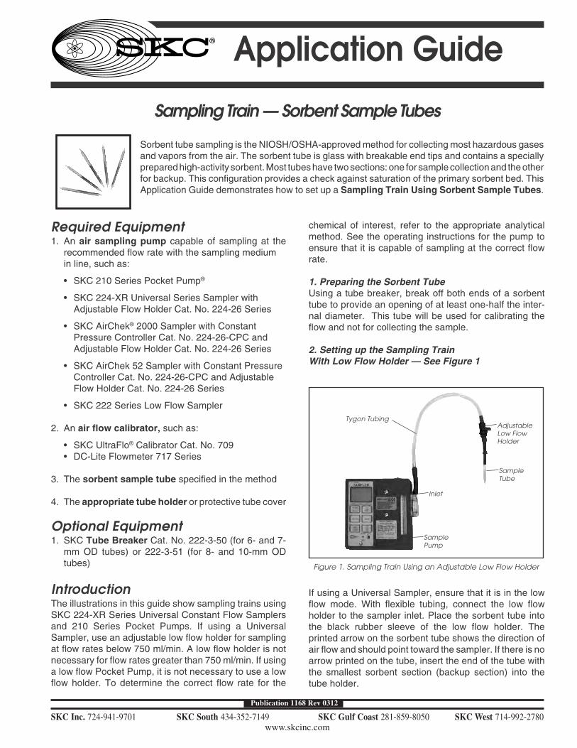
Sorbent Tube Sampling
Air samples to be analyzed for aldehydes, amines, ammonia, carboxylic acids, hydrogen chloride,
hydrogen cyanide, mercury (elemental), and sulfur dioxide will be collected using individual
sorbent tube sampling trains, each consisting of an air sampling pump and sorbent tube. Sorbent
tube sampling trains used for sampling ambient air will be allowed to sample over a period of
approximately four (4) hours. Each sampling pump and sorbent tube train will be set to a
method-specific flow rate in the field at the time each sample is started.
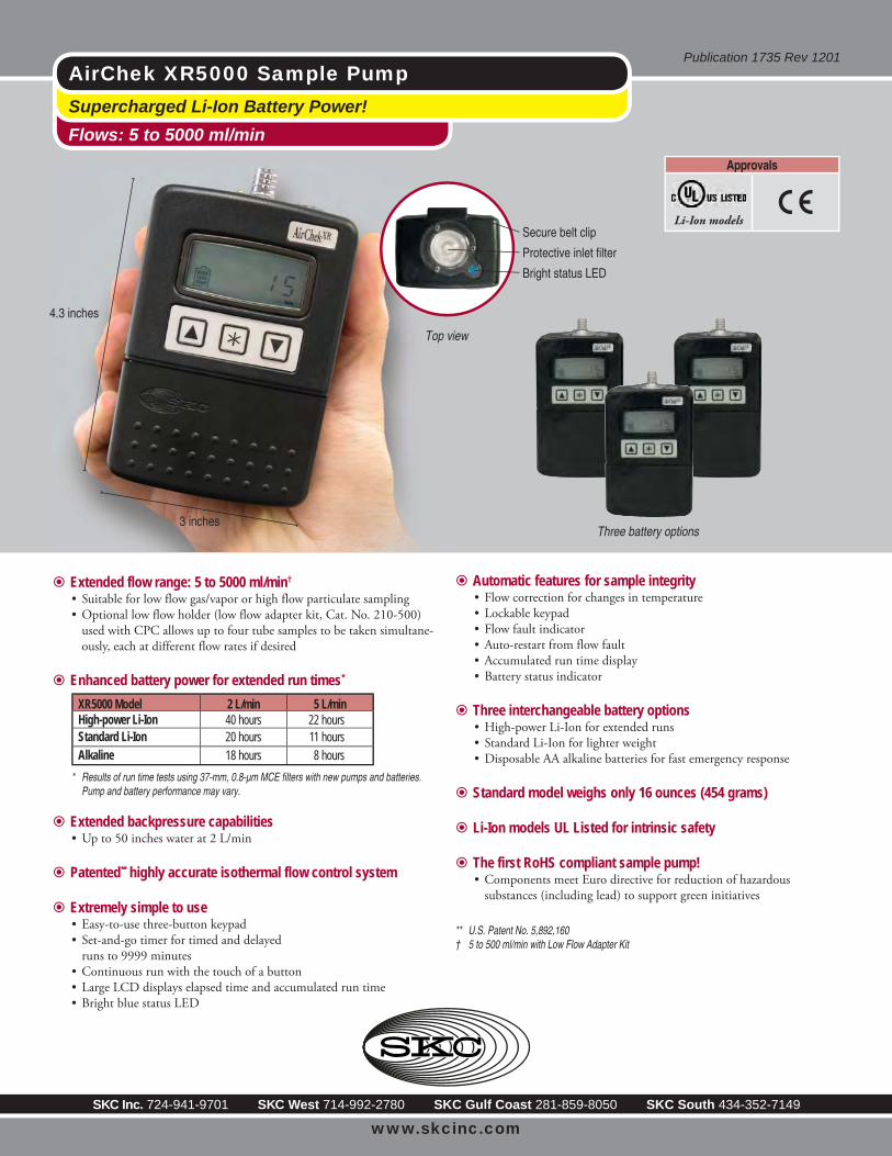
Air sampling pumps will consist of SKC AirCheck XR5000 units supplied SKC, Inc. ("SKC") of
Eighty Four, Pennsylvania. Sorbent tubes to be used for each method are indicated in Table 1.
11
Each pump will be paired with a method-specific sorbent tube and pre-set with a specific flow
rate setting for the respective tube method (e.g., acetaldehyde). Pumps that are adjusted for each
tube method will be affixed with a label indicating that flow adjustments have been pre-set. At
the time of deployment at each sampling location, each pump will be flow calibrated using a DC-
Lite Flowmeter supplied by SKC. Flow calibration, flow readings, and start times for each
sorbent tube sampling train will be recorded onto a pump calibration form in the field (see
Attachment B). The flow rate will also be checked at the end of sampling.
Sampling pumps will be flow-calibrated and started individually around approximately the same
time. After a sampling period of approximately 4-hours, the sampling pumps will then be flow-
checked and shut down to conclude the sampling for each pump and tube sampling train. Sorbent
tube sampling, including pump calibration, tube preparation and flow check, will be performed in
general accordance with the procedures indicated in Attachment G. The basic procedures for
collecting a sorbent tube sample for each individual tube method are as follows:
• Record the current sampling location on the appropriate field forms (include map ID and/or GPS coordinates).
• Connect a representative sampler tube (e.g., acetaldehyde) to be used for flow calibration to the DC-Lite flowmeter. Connect the flowmeter to the XR5000 air pump pre-set for the respective tube method.
• Calibrate sampling pump with the representative sampler and flow meter in line. Label the pump, noting the parameter to be sampled. Adjust pump to desired flow rate and record the flow rate onto the Air Sampling Pump Calibration Log. Remove the sorbent tube and set aside for post sampling flow rate verification.
• Break the ends off a new sorbent tube immediately prior to sampling. Attach sorbent tube to pump with flexible tubing. Make sure that the tube matches the parameter labeled on the pump. Record start time onto the Air Sampling Pump Calibration Log.
• Sample at an accurately known flow rate for four hours. The sample flow rate can be determined at the end of sampling, while the pump is running, or after shutdown if the flow rate has not been changed.
• Cap the sorbent tube and pack securely for shipment with bagged refrigerant. DO NOT shut down the pump at this time. Each tube should go in a labeled Ziploc bag, noting sample ID and parameter, date and time. Labels should be prepared in such a way that they will not be ruined by water or refrigerant. Samples may be stored at 4C until they are shipped. Record the sampling information onto the Chain of Custody form.
• Using the same setup as for initial calibration, measure the flow rate again with the same dedicated sorbent tube specific to the pump used for that method. Record the final flow rate onto the Air Sampling Pump Calibration Log.
Specific sorbent tube methods to be used for the sampling and analysis program for this project
are summarized below. These methods are published by the National Institute for Occupational
12
Safety and Health ("NIOSH"), the Occupational Safety and Health Administration ("OSHA"),
and U.S. EPA. The complete method descriptions associated with the proposed sorbent tube
testing to be conducted for this project are readily-available from the above sources.
Aldehydes
U.S. EPA Method TO-11A will be used for analysis of aldehydes. The standard operating
procedure for this method’s sample collection is summarized as follows:
• Calibrate each personal sampling pump with a representative sampler in line. Record flow rate.
• Break the ends of the samplers immediately prior to sampling. Attach sampler to pump with flexible tubing.
• Sample at an accurately known flow rate between 0.1 and 2.0 L/min for a total sample size of 3 to 30L. Aim for 1.0 L/min for 4 hours and 240L.
• Cap the samplers and pack securely for shipment with bagged refrigerant.
• Using a flow meter, calibrate the flow rate again with the same representative sampler. Record final flow rate.
Amines
NIOSH Method 2010M will be used for analysis of amines. The standard operating procedure
for this method’s sample collection is summarized as follows:
• Calibrate each personal sampling pump with a representative sampler in line. Record flow rate.
• Break the ends of the samplers immediately prior to sampling. Attach sampler to pump with flexible tubing.
• Sample at an accurately known flow rate between 0.01 and 1.0 L/min for a total sample size of 3 to 30L. Aim for 0.125 L/min for 4 hours and 30L.
• Cap the samplers and pack securely for shipment with bagged refrigerant.
• Using a flow meter, calibrate the flow rate again with the same representative sampler. Record final flow rate.
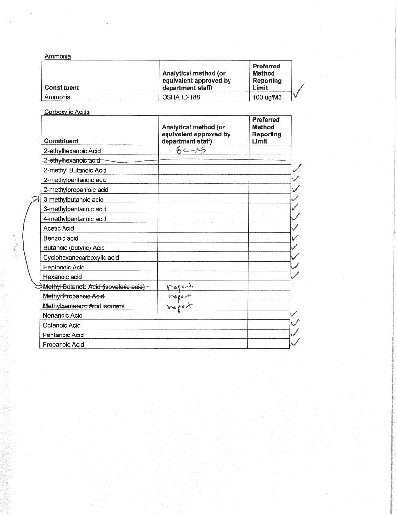
Carboxlyic Acids
A GC-MS method will be used by the analytical laboratory for analysis of carboxylic acids. This
is an in-house method developed by AAC. Collection will be similar to other sorbent tube
13
methods. The standard operating procedure for this method’s sample collection is summarized as
follows:
• Calibrate each personal sampling pump with a representative sampler in line. Record flow rate.
• Break the ends of the samplers immediately prior to sampling. Attach sampler to pump with flexible tubing.
• Sample at an accurately known flow rate between 0.01 and 1.0 L/min for a total sample size of 3 to 30L. Aim for 0.417 L/min for four hours and 100L.
• Cap the samplers and pack securely for shipment with bagged refrigerant.
• Using a flow meter, calibrate the flow rate again with the same representative sampler. Record final flow rate.
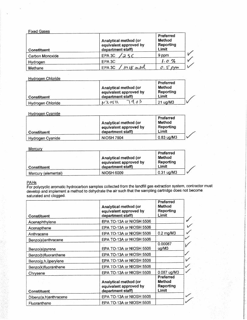
Hydrogen Chloride
NIOSH Method 7903 will be used for analysis of hydrogen chloride. The standard operating
procedure for this method’s sample collection is summarized as follows:
• Calibrate each personal sampling pump with a representative sampler in line. Record flow rate.
• Break ends of sampler immediately before sampling. Attach sampler to personal sampling pump with flexible tubing.
• Sample at an accurately known flow rate between 0.2 and 0.5 L/min for a total sample size of 3 to 100L. Aim for 0.417 L/min for four hours and 100L.
• Cap the samplers and pack securely for shipment.
• Using a flow meter, calibrate the flow rate again with the same representative sampler. Record final flow rate.
Ammonia
OSHA Method ID-188 will be used for analysis of ammonia. The standard operating procedure
for this method’s sample collection is summarized as follows:
• Calibrate each personal sampling pump with a representative sampler in line. Record flow rate.
• Break the ends of the samplers immediately prior to sampling. Attach sampler to pump with flexible tubing.
• Sample at an accurately known flow rate between 0.01 and 1.0 L/min for a total sample size of 3 to 30L. Aim for 0.1 L/min for four hours and 24L.
14
• Cap the samplers and pack securely for shipment.
• Using a flow meter, calibrate the flow rate again with the same representative sampler. Record final flow rate.
Hydrogen Cyanide
NIOSH Method 7904 will be used for analysis of hydrogen cyanide. The standard operating
procedure for this method’s sample collection is summarized as follows:
• Calibrate each personal sampling pump with a representative sampler in line. Record flow rate.
• Sample at 0.5 to 1 L/min for a total sample size of 10 to 180 L.
• Cap sampler and pack securely for shipment.
• Using a flow meter, calibrate the flow rate again with the same representative sampler. Record final flow rate.
Mercury
NIOSH Method 6009 will be used for analysis of mercury. The standard operating procedure for
this method’s sample collection is summarized as follows:
• Calibrate each personal sampling pump with a representative sampler in line. Record flow rate.
• Break ends of sampler immediately prior to sampling. Attach sampler to pump with flexible tubing.
• Sample at an accurately known rate of 0.15 to 0.25 L/min for a total sample size between 2 and 100 L.
• Cap sampler and pack securely for shipment.
• Using a flow meter, calibrate the flow rate again with the same representative sampler. Record final flow rate.
Sulfur Dioxide
OSHA Method ID-200 will be used for analysis of sulfur dioxide. The standard operating
procedure for this method’s sample collection is summarized as follows:
• Calibrate each personal sampling pump with a representative sampler in line. Record flow rate.
15
• Break the ends of the samplers immediately prior to sampling. Attach sampler to pump with flexible tubing.
• Sample at an accurately known flow rate between 0.01 and 1.0 L/min for a total sample size of 3 to 30L. Aim for 0.05 L/min for four hours and 12L.
• Cap the samplers and pack securely for shipment.
• Using a flow meter, calibrate the flow rate again with the same representative sampler. Record final flow rate.
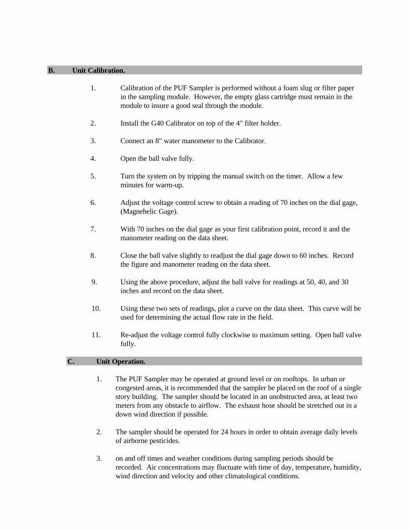
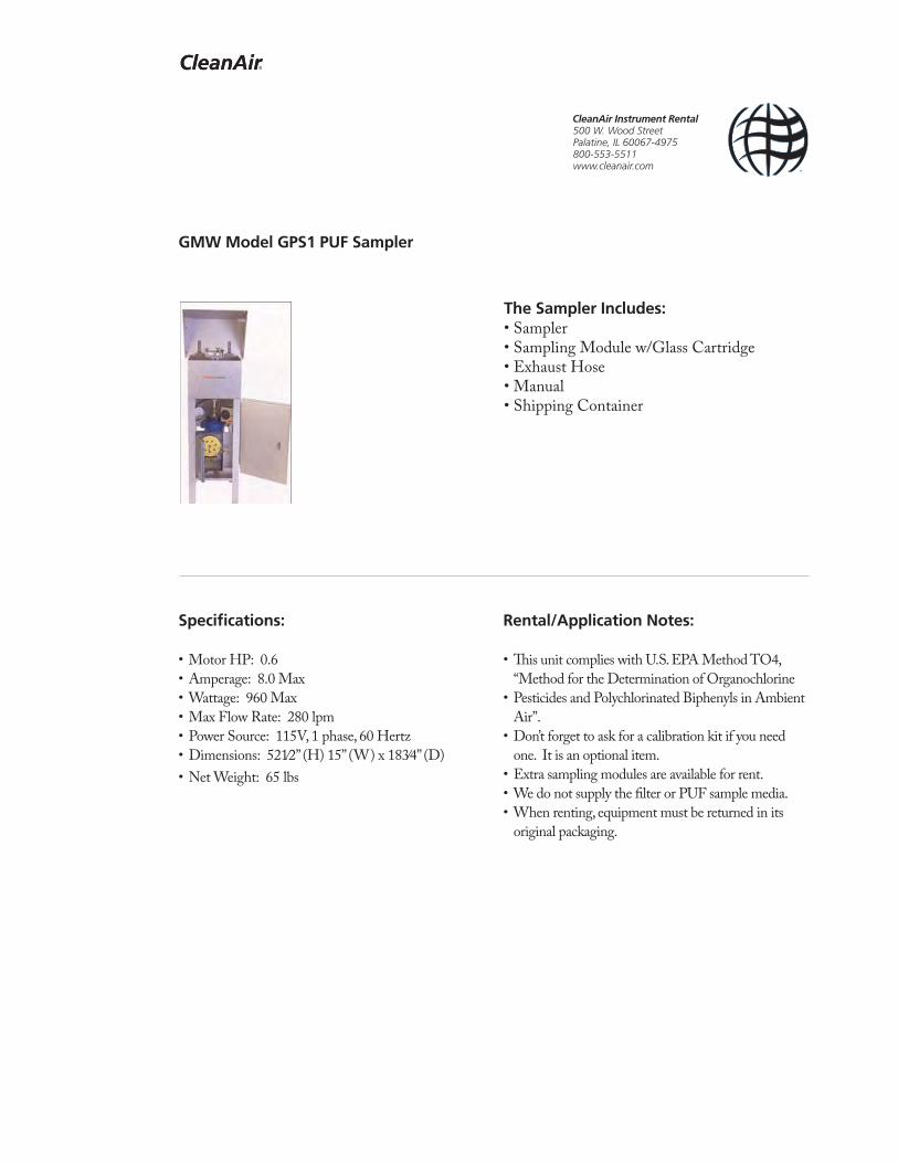
High-Volume PUF Cartridge Sampling
Air samples to be analyzed for dioxins/furans and PAHs will be collected using high-volume
polyurethane foam ("PUF") cartridge samplers. Three (3) GMW Model GPS1 PUF samplers will
be obtained from Clean Air Instrument Rental of Palentine, Illinois. Project Personnel will
deploy these sampling units to designated sampling locations. Ambient air PUF samples are
planned to be collected at two (2) off-site locations and one (1) on-site location. Three (3) PUF
samples are also planned to be collected from the landfill source gas. One field blank sample will
also be collected. These samples will be collected by connecting the PUF sampler inlet to a
sampling manifold that has been fixed into the landfill FML.
PUF sampling will be performed by a subcontractor to SWAPE. PUF sampling, including unit
calibration and operation, will be performed in general accordance with the procedures specified
in the manufacturer's operation manual (see see portion in Attachment H). A complete copy of
the operation manual will be distributed to Project Personnel. The basic procedures for operation
of the PUF sampler are summarized as follows:
• IMPORTANT. Calibrate instrument in accordance with manufacturer's operating manual before each day's use (see CALIBRATION instructions below).
• Refer to Unit Calibration section in the Operating Manual.
• Turn the system on by tripping the manual switch on the timer. Allow a few minutes for warm-up.
• Perform a calibration of the PUF sampler using an empty glass cartridge and G40 Calibrator as specified in the Operating Manual. Adjust unit settings to record Magnehelic Gage readings on data sheet.
• Install PUF sampling module into unit (see the Operating Manual).
• NOTE. Air flow-readings should be taken (dial gage) at the beginning and end of each sampling period. Differences between the beginning and ending flow rates should be averaged out to obtain an overall flow rate.
• Initiate sampling by tripping the manual switch on the timer.
16
• NOTE that for sampling the landfill gas source the sampling time will be significantly shorter than for ambient air sampling. The actual sampling time will be determined in the field.
• Check the flow-readings and record the flow rate, date, and start time onto the appropriate field forms (e.g., Daily Field Activities Log, Chain of Custody).
• The sample should be collected over a period of approximately 24 hours for ambient air sampling.
• Check the progress of sampling event over the course of the 24-hour, or shorter, period to make sure the unit is operating properly. At some sampling locations, electrical power will be supplied to the unit using a gasoline-powered generator. This generator should be periodically checked to ensure continuous operation.
• At the end of the desired sampling period, shut down the unit and record the flow rate and end time onto the appropriate field forms (e.g., Daily Field Activities Log, Chain of Custody).
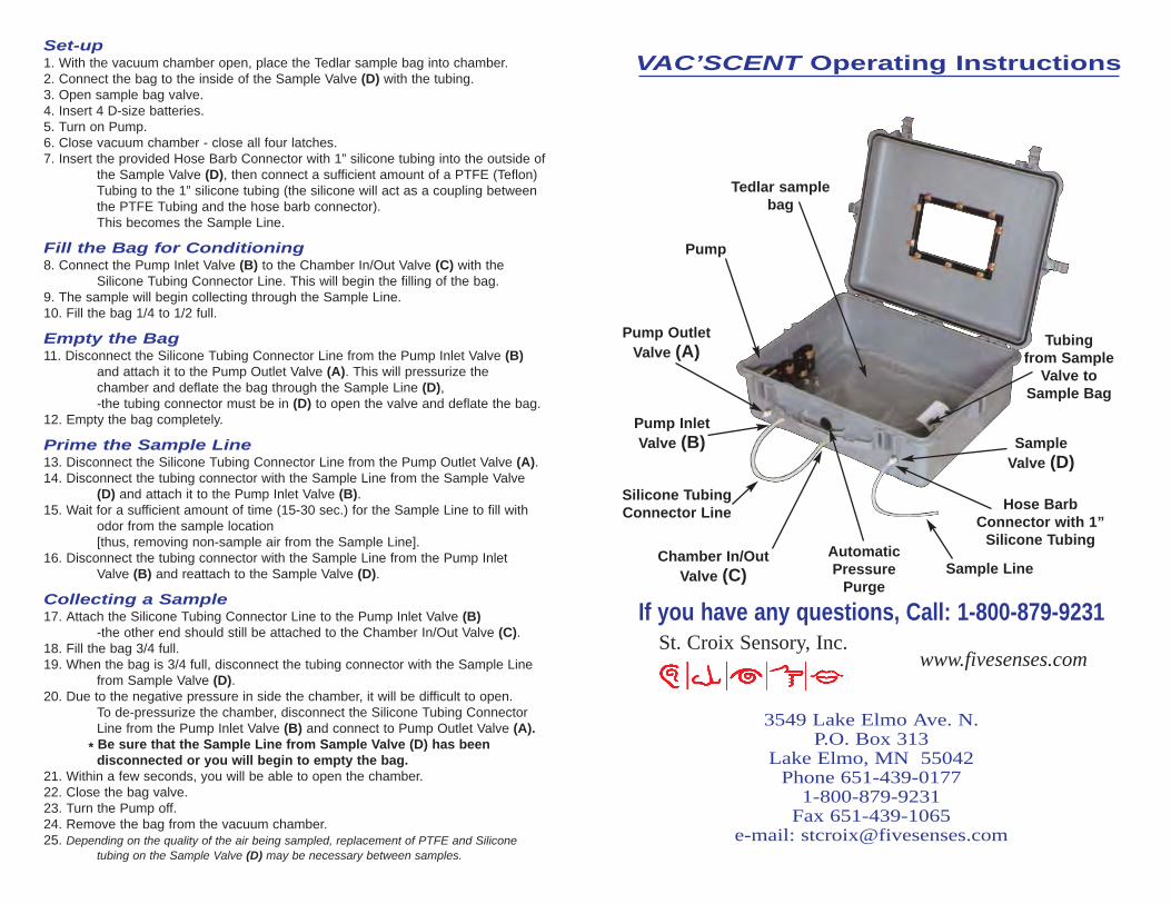
Vacuum Chamber Sampling
Air samples will be collected for the quantification of perceived odors using a vacuum chamber
sampling box and Tedlar® air sampling bags. For each air sample, a Tedlar® sampling bag will
be placed into a vacuum sampling box and fitted with dedicated tubing to an internal air pump
and valve fittings that connect to additional exterior valves. Tedlar® sampling bags and vacuum
sampling equipment will be obtained from St. Croix Sensory, Inc. ("St. Croix") of Stillwater,
Minnesota. Tedlar bag sampling using the vacuum chamber will be performed in general
accordance with the procedures specified in the manufacturer's operation manual (see see portion
in Attachment I). A complete copy of the operation manual will be distributed to Project
Personnel. The basic procedures for operation of the vacuum chamber sampler are summarized
as follows:
• Record the current sampling location on the appropriate field forms (include map ID and/or GPS coordinates).
• Open the vacuum chamber and insert batteries, turn on pump.
• Insert a hose barb connector with silicone tubing into the outside of the Sample Valve (D), then connect a sufficient amount of a tubing to the silicone tubing to act as a coupling between the tubing and the hose barb connector. This becomes the Sample Line.
• Place a Tedlar® air sampling bags into the chamber, open the valve on the bag and connect the Sample Line.
• Follow directions for Fill the Bag for Conditioning on the Operating Instructions. This step will fill the Tedlar® air sampling bag with ambient air.
• Follow directions for Empty the Bag on the Operating Instructions. This step will purge the ambient air from the bag.
17
• Follow directions for Prime the Sample Line on the Operating Instructions. This step will purge non-ambient air from the Sample Line.
• Follow directions for Collecting a Sample on the Operating Instructions. NOTE that the sample bag should only be filled until is approximately 3/4-full. Rearrange the valve connectors on the exterior of the vacuum chamber box to depressurize the unit.
• Open the vacuum chamber, close the Tedlar® air sampling bag valve, and close the chamber for storage.
• Record the Sample ID, date, and time onto the Tedlar® air sampling bag label and the appropriate field forms (e.g., Daily Field Activities Log, Chain of Custody).
18
5. ANALYTICAL APPROACH
Several laboratories will be used for analytical testing of air samples collected during the Weekly,
Immediate, and Comprehensive Sampling Events. Samples collected for the various testing
parameters will be labeled, handled and shipped with Chain of Custody documentation in
accordance with the procedures identified below.
5.1. CHEMICAL ANALYSIS
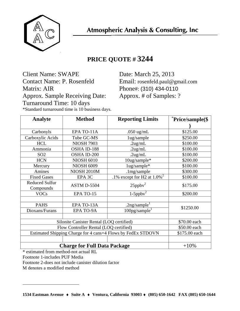
Most of the chemical analytical testing is planned to be conducted by Atmospheric Analysis and
Consulting, Inc. ("AAC") of Ventura, California. AAC will subcontract two other laboratories
for analyses of sorbent tube air samples for mercury and PUF cartridge samples for dioxins/furans
and PAHs. All laboratories will analyze samples according to the designated methods. The
laboratories are responsible for following all standard operating procedures and QA/QC
guidelines. The laboratory methods are listed below and the proposed laboratory method
reporting limits are summarized in Attachment J.
• EPA TO-11A will be used for Aldehydes.
• NIOSH 2010M will be used for Amines,
• Tube GC-MS will be used for Carboxylic Acids,
• NIOSH 7903 will be used for Hydrogen Chloride.
• OSHA ID-188 will be used for Ammonia.
• NIOSH 7904 will be used for Hydrogen Cyanide.
• NIOSH 6009 will be used for Mercury.
• OSHA ID-200 will be used for Sulfur Dioxide.
• EPA TO-9A will be used for Dioxins and Furans.
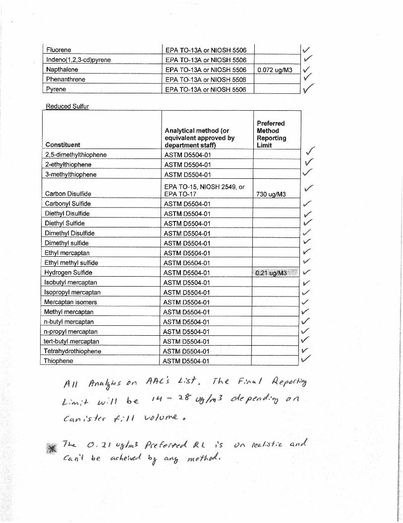
• EPA TO-13A will be used for PAH’s and SVOC’s.
• EPA TO-15 will be used for VOC’s.
• ASTM D5504-01 will be used for Reduced Sulfur Compounds.
• EPA 3C will be used for Fixed Gases.
• ASTM 679 will be used for Odor Evaluation.
19
5.2. ODOR EVALUATION
Odor evaluation will be conducted by St. Croix. Air samples will be evaluated at St. Croix by
trained human assessors (the assessor panel) observing presentations of the odorous air samples.
Air samples are characterized using five basic parameters of human response, including: odor
thresholds, odor intensity, odor persistency, hedonic tone, and odor characterization.
Descriptions of the odor parameters evaluated by St. Croix is presented in Appendix K.
Odor evaluation will be conducted in accordance with American Society for Testing and
Materials ("ASTM") Method E679-04 (Standard Practice for Determination of Odor and Taste
Thresholds by a Forced-Choice Ascending Concentration Series Method of Limits).
5.3. LABORATORY CONTACTS
Principal Laboratory Services Dr. Sucha Parmar Atmospheric Analysis and Consulting, Inc. 1534 Eastman Avenue, Suite A Ventura, CA 93003 805-650-1642
Dioxins/Furans and PAHs Analysis Scott Unze Pace Analytical Services, Inc. 1700 Elm St SE Minneapolis, MN 55414 612-607-1700 (office)
Odor Evaluation Services Donna McGinley St. Croix Sensory, Inc. 1150 Stillwater Blvd. N. Stillwater, MN 55042 800-879-9231
5.4. DATA MANAGEMENT AND DELIVERY
Electronic analytical reports and electronic data deliverables for all air sampling activities will be
furnished to the Project Manager by AAC. Level IV reporting will be provided for all laboratory
analytical testing. AAC will also provide the analytical data in electronic spreadsheet format,
such as Microsoft Excel format. The Project Manager will coordinate with the MDNR to
determine the formats desired for transmittal of the laboratory results. Summary reports that
document the results of air monitoring activities will be prepared by Project Personnel and
delivered to MDNR by the Project Manager. The schedule for delivery of summary reports and
electronic data deliverables will be coordinated with MDNR.
20
6. QUALITY ASSURANCE
The Project Manager will manage quality assurance for the sample collection and field activities
associated with this project. The designated laboratories utilized during the investigation will be
responsible for QA/QC related to the laboratory analytical testing. Laboratory QC samples will
include laboratory duplicates, spikes, blanks, and other performance samples. The laboratory will
perform QA/QC procedures to ensure routine laboratory precision objectives in accordance with
their standard operating procedures and the requirements of the specific methods used for testing.
6.1. SAMPLE HANDLING AND CUSTODY PROCEDURES
After sample collection and identification, samples will be maintained under Chain of Custody
procedures. A Chain of Custody record will be completed each time a sample or group of
samples is prepared in the field and transmitted with each sample shipment to the laboratory. The
Chain of Custody record will repeat the information on each sample label and will serve as
documentation of handling during shipment. A copy of this Chain of Custody record will remain
with the shipped samples at all times, and another copy will be retained by the member of the
sampling team who originally relinquished the samples.
6.2. SAMPLING AND FIELD QC PROCEDURES
Samples will be collected using equipment and procedures appropriate to the matrix, parameters,
and sampling objectives. The volume of the sample collected will be sufficient to perform the
analysis requested. Samples will be stored in the proper types of containers and preserved in a
manner for the analysis to be performed per laboratory guidelines. Samples will be collected
using equipment in accordance with the standard operating procedures for each method. An
additional blank sample for each parameter will be provided for the comprehensive event. No
duplicate samples will be taken.
Dedicated sampling equipment and sample containers will be maintained in a clean, segregated
area. Project Personnel responsible for sampling will maintain cleanliness and will use and
change gloves between each sample collection/handling activities. Each sample will be assigned a
unique identification number and assembled and catalogued prior to shipping to the designated
laboratory. SUMMA® Canisters will be handled per laboratory and manufacturers’ guidance,
observing safe and effective collection and preservation of the data.
6.3. FIELD DOCUMENTATION
All field documentation will be recorded, legibly, in ink. Project Personnel will use pre-printed
field worksheets to accurately document all field activities: on-site conditions; field
21
measurements; sample collection information; field instrument and calibration information; and
other pertinent site-related information during monitoring and sampling activities. All
information will be recorded in permanent black ink. Standard field forms that will be used for
this project are presented in Attachment A.
6.4. INSTRUMENT MAINTENANCE
A combination of purchased and rented equipment will be used for the planned air monitoring
and air sampling activities. Project Personnel will be responsible for maintaining the monitoring
and sampling equipment in a manner that ensures optimal equipment condition and minimizes
operational down-time. The majority of the equipment will be well conditioned for use for the
project. Monitoring equipment that is utilized for repeated Daily Monitoring Events, and Weekly
and Immediate Sampling Events, will be maintained by the local subcontractor to SWAPE
located in the St. Louis area. A budget for continued maintenance of the field equipment has
been incorporated into the project budget.
Sample type Sampling Method / EquipmentAnalytical Method
Notes:1) The schedule above is preliminary and subject to change. The analytical methods for sampling events may be adjusted as requested by MDNR.2) The eleven (11) locations includes 3 upwind, 3 downwind, 2 on-site (ambient air), and 3 under the FML.3) The four (4) locations includes 2 upwind and 2 downwind for both Weekly and Immediate Sampling Events.4) The seven (7) locations includes 1 upwind, 1 downwind, 1 on-site (ambient air), 3 under the FML, and one blank.5) The eight (8) locations includes 6 upwind/downwind and 2 on-site (ambient air).6) The method will be performed by Atmospheric Analysis and Consulting, Inc. using GC-MS.6) Sampling locations and scheduling may vary due to access restriction, landfill activities and events.7) Samples taken under FML will be of shorter duration, to be determined.
Table 1 - Air Sampling Methods and Schedule
One high-volume polyurethane foam (PUF) cartridge sampler for analysis of dioxins/furans and PAHs 7 Locations4 24 hours
11 Locations 4 HoursOne six-liter SUMMA® canister with 4-hour flow
restrictor for analysis of VOCs, reduced sulfur compounds, and fixed gases
NS
Page 1 of 1
ATTACHMENT A
Standard Field Forms for Bridgeton Sanitary Landfill Air Quality Assessment
COMPLETED BY: PERSONNEL:
DATE:
PAGE: of
DAILY FIELD ACTIVITIES LOG
Bridgeton Sanitary Landfill Air Quality Assessment
SOIL / WATER / AIR PROTECTION ENTERPRISE
FIELD NOTES
TIME (24-HR) DESCRIPTION OF ACTIVITIES
SOIL / WATER / AIR PROTECTION ENTERPRISE
COMPLETED BY: PERSONNEL:
DATE:
PAGE: of
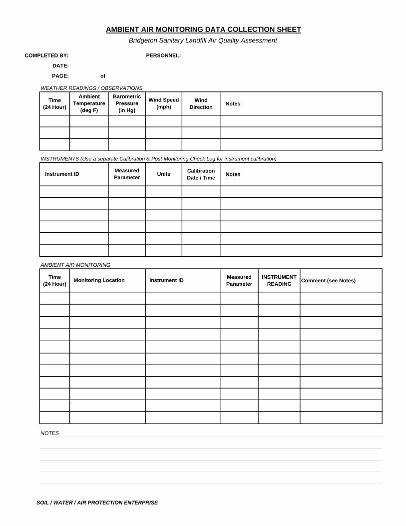
WEATHER READINGS / OBSERVATIONS
Time (24 Hour)
Wind Direction
Notes
INSTRUMENTS (Use a separate Calibration & Post-Monitoring Check Log for instrument calibration)
Calibration Date / Time
Notes
AMBIENT AIR MONITORING
Time (24 Hour)
Measured Parameter
INSTRUMENT READING
Comment (see Notes)
Ambient Temperature
(deg F)
Barometric Pressure
(in Hg)
Wind Speed (mph)
AMBIENT AIR MONITORING DATA COLLECTION SHEET
Bridgeton Sanitary Landfill Air Quality Assessment
Measured Parameter
Units Instrument ID
Monitoring Location Instrument ID
NOTES
SOIL / WATER / AIR PROTECTION ENTERPRISE
COMPLETED BY: PERSONNEL:
DATE:
PAGE: of
AMBIENT AIR MONITORING
Time (24 Hour)
Measured Parameter
INSTRUMENT READING
Comment (see Notes)
NOTES
Monitoring Location Instrument ID
AMBIENT AIR MONITORING DATA COLLECTION SHEET
Bridgeton Sanitary Landfill Air Quality Assessment
SOIL / WATER / AIR PROTECTION ENTERPRISE
COMPLETED BY: PERSONNEL: WEATHER:
DATE:
PAGE: of
Calibration Gas
Instrument Reading
Calibration Gas
Instrument Reading
Calibration Gas
Instrument Reading
Calibration Gas
Instrument Reading
NOTES
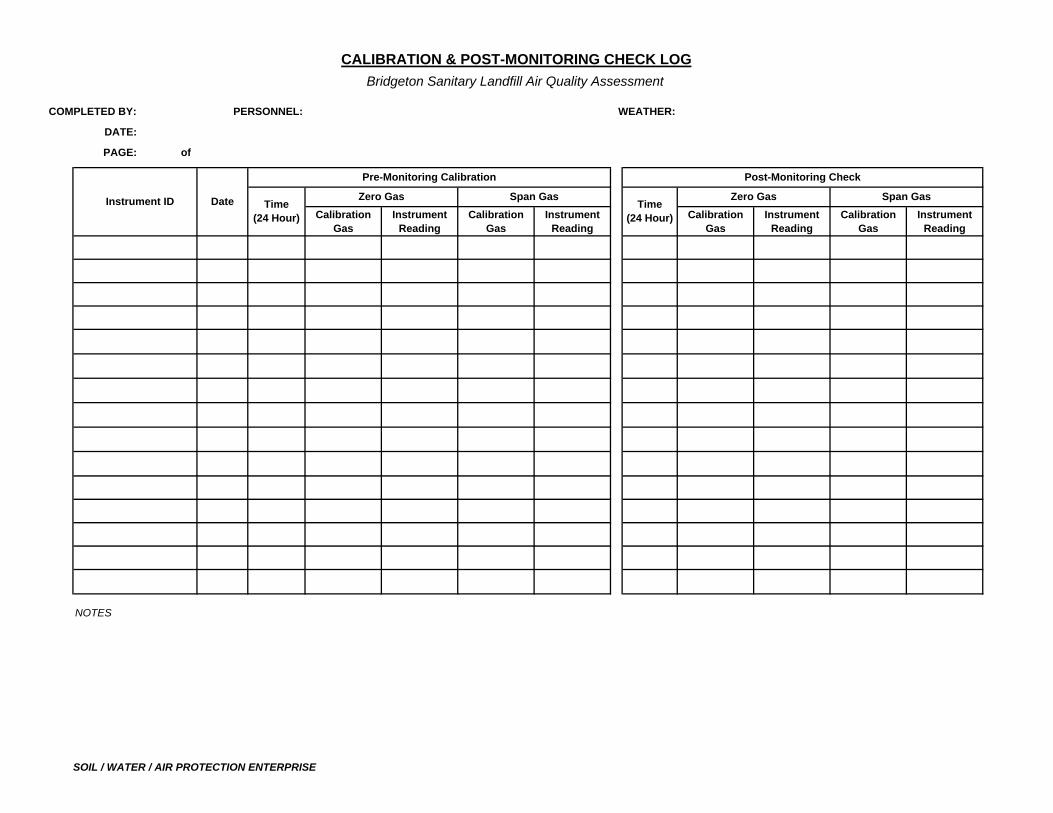
Pre-Monitoring Calibration
Date Time (24 Hour)
Zero Gas Span Gas Instrument ID Zero Gas Span GasTime
(24 Hour)
Post-Monitoring Check
CALIBRATION & POST-MONITORING CHECK LOG
Bridgeton Sanitary Landfill Air Quality Assessment
SOIL / WATER / AIR PROTECTION ENTERPRISE
COMPLETED BY: PERSONNEL:
DATE:
PAGE: of
CALIBRATION INSTRUMENT :
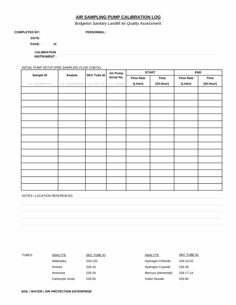
INITIAL PUMP SETUP (PRE-SAMPLING FLOW CHECK)
e.g. 123456
TUBES: ANALYTE SKC TUBE ID ANALYTE SKC TUBE ID
Aldehydes 226-120 Hydrogen Chloride 226-10-03
Amines 226-10 Hydrogen Cyanide 226-28
Ammonia 226-29 Mercury (elemental) 226-17-1A
Carboxylic Acids 226-55 Sulfur Dioxide 226-80
AIR SAMPLING PUMP CALIBRATION LOG
Bridgeton Sanitary Landfill Air Quality Assessment
Sample ID
e.g. acetaldehyde
Analyte
e.g. acetaldehyde
SKC Tube ID
e.g. 226-120
Time
(24 Hour)
NOTES / LOCATION REFERENCES
START END
Flow Rate
(L/min)
Time
(24 Hour)
Flow Rate
(L/min)
Air Pump Serial No.
SOIL / WATER / AIR PROTECTION ENTERPRISE
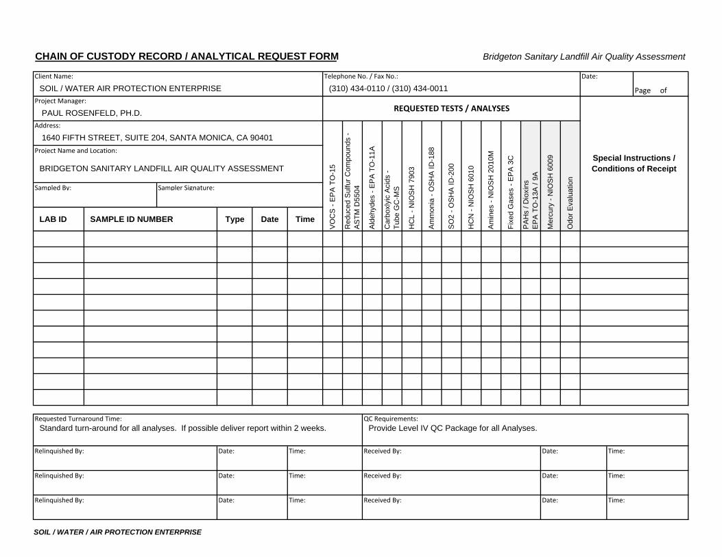
CHAIN OF CUSTODY RECORD / ANALYTICAL REQUEST FORM Bridgeton Sanitary Landfill Air Quality Assessment
Client Name: Telephone No. / Fax No.: Date:
SOIL / WATER AIR PROTECTION ENTERPRISE (310) 434-0110 / (310) 434-0011 Page of Project Manager:
PAUL ROSENFELD, PH.D.Address:
1640 FIFTH STREET, SUITE 204, SANTA MONICA, CA 90401Project Name and Location:
BRIDGETON SANITARY LANDFILL AIR QUALITY ASSESSMENT
Sampled By: Sampler Signature:
LAB ID SAMPLE ID NUMBER Type Date Time
Requested Turnaround Time: QC Requirements:
Relinquished By: Date: Time: Received By: Date: Time:
Relinquished By: Date: Time: Received By: Date: Time:
Relinquished By: Date: Time: Received By: Date: Time:
Am
mon
ia -
OS
HA
ID-1
88
SO
2 - O
SH
A ID
-200
Red
uced
Sul
fur C
ompo
unds
- A
STM
D55
04
PA
Hs
/ Dio
xins
E
PA
TO
-13A
/ 9A
HC
N -
NIO
SH
601
0
Am
ines
- N
IOS
H 2
010M
Fixe
d G
ases
- E
PA
3C
Provide Level IV QC Package for all Analyses. Standard turn-around for all analyses. If possible deliver report within 2 weeks.
REQUESTED TESTS / ANALYSES
VO
CS
- E
PA
TO
-15
Alde
hyde
s - E
PA
TO
-11A
Car
boxl
yic
Aci
ds -
Tube
GC
-MS
HC
L - N
IOS
H 7
903
Special Instructions / Conditions of Receipt
Mer
cury
- N
IOS
H 6
009
Odo
r Eva
luat
ion
SOIL / WATER / AIR PROTECTION ENTERPRISE
ATTACHMENT B
Nasal Ranger Field Olfactometer Operation Manual (portion)
INTRODUCTION TO FIELD OLFACTOMETRY The Nasal Ranger® Field Olfactometer is the “state-of-the-art” in field olfactometry for confidently measuring and quantifying odor strength in the ambient air. The Nasal Ranger® Field Olfactometer, a portable odor detecting and measuring device, determines ambient odor “Dilution-to-Threshold” (D/T) values objectively. Field olfactometry can be used as a proactive monitoring or enforcement tool for confident odor measurement at property lines and in the neighboring community. Quantifying ambient odor is often needed for the following purposes:
2. Comparison of operating practices (i.e. evaluating alternatives),
3. Documenting specific events or episodes (i.e. defensible, credible evidence),
4. Monitoring compliance (i.e. compliance assurance for permits),
5. Determination of compliance (i.e. permit renewal),
6. Determination of status (i.e. baseline data for expansion planning),
7. Investigation of odor control effectiveness (i.e. scientific testing),
8. Verification of odor dispersion modeling (i.e. model calibration),
9. Determination of specific odor sources (i.e. investigation of complaints),
10. Verification of complaints (i.e. notice of violation).
The Nasal Ranger® Field Olfactometer, as a nasal organoleptic instrument, provides field olfactometry with a scientific method for dependable ambient odor quantification. In 1958 the U.S. Public Health Service sponsored the development of an instrument and procedure for field olfactometry (ambient odor strength measurement) through Project Grants A-58-541, A-59-541, and A-60-541. The Barnebey-Cheney Company originally manufactured a field olfactometer instrument based on these grants, known as a “scentometer”. A Nasal Ranger® Field Olfactometer creates a calibrated series of discrete dilutions by mixing the odorous ambient air with odor-free (carbon) filtered air. Field olfactometry defines each discrete dilution level as a “Dilution-to-Threshold,” D/T, ratio. The “Dilution-to-Threshold” ratio is a measure of the number of dilutions needed to make the odorous ambient air “non-detectable”. Field olfactometry calculates the “Dilution-to-Threshold” (D/T) ratio as:
Volume of Carbon-Filtered Air D/T = ---------------------------------------
Push the POWER Button ON and Position the D/T Dial at the First BLANK Position located between 2-D/T and 60-D/T and inhale at
your NORMAL breathing rate through the Nasal Mask for 1-minute.
Turn the D/T Dial Clockwise to the 60-D/T Position and inhale TWICE at the Target Inhalation Rate of 16-20LPM through the Nasal Mask.
Did I Smell an ODOR ?
Turn the D/T Dial to the next BLANK Position and resume your NORMAL breathing rate through the Nasal Mask; and ASK YOURSELF:
Turn the D/T Dial to the 30-D/T Position and inhale TWICE at the Target Inhalation Rate of 16-20LPM through the Nasal Mask.
REPEAT the above steps with BLANK Positions to “rest” the nose during NORMAL breathing and “TEST” the ambient air with subsequent D/T Positions (15, 7, 4, 2) during inhalation at
the Target Inhalation Rate of 16-20LPM through the Nasal Mask.
Turn the D/T Dial to the next BLANK Position and resume your NORMAL breathing rate through the Nasal Mask; and ASK YOURSELF:
OPERATING PRINCIPLE The Nasal Ranger® Field Olfactometer, a nasal organoleptic instrument, directly measures and quantifies odor strength in the ambient air using the Operating Principle of mixing odorous ambient air with odor-free filtered air in discrete volume ratios. The discrete volume ratios are called “Dilution-to-Threshold” ratios (D/T ratios). The user’s nose is placed firmly inside the nasal mask against the replaceable “comfort seal”. The user inhales through the nasal mask at a comfortable breathing rate while standing at rest. The nasal mask has an outlet for exhaled air to exhaust downward. Therefore, the user inhales through the Nasal Ranger and exhales downward through the outlet check valve. The user can stand at rest and continue comfortable breathing exclusively through the Nasal Ranger Field Olfactometer. A Power Button located on the Nasal Ranger Housing, directly below the nasal mask, is pushed once by the user to turn the Power ON. To turn the Power OFF manually the Power Button must be pressed for 3-seconds. After 5-minutes of non-use the Power will automatically turn OFF. A set of LED lights that are recessed on top of the Nasal Ranger housing indicate when the inhalation flow rate is within the “factory calibration flow rate” of 16-20 liters per minute. The four (4) LED lights have the following functions:
1st LED (on Left): Indicates POWER ON. After 45-seconds of non-use this first LED blinks slowly in a “Power Save Mode”. When the user inhales and initiates flow the LED will “wake” from the Power Save Mode and remain ON. After 5-minutes of non-use the Power will turn OFF. The Power Button must be pushed once by the user to restart the Power. 2nd LED: ON when the user is inhaling at a flow rate of less than 16-lpm. 3rd LED: ON when the user inhales at a flow rate of greater that 16-lpm and less than 20-lpm. 4th LED: ON when the user inhales at a rate greater than 20-lpm.
Therefore, the user of the Nasal Ranger Field Olfactometer learns to inhale at a rate sufficient to ONLY light up the third LED and be assured that the inhalation is within the factory calibrated flow rate range of 16-20lpm. The Nasal Ranger’s Operating Principle of mixing odorous ambient air with odor-free filtered air in discrete volume ratios is achieved using two airflow paths:
1. Flow through the odor-filter cartridge and
2. Flow through one of the orifices in the D/T (Dilution-to-Threshold) Dial. The first airflow path is the “filtered air” path through both odor-filter cartridges that are attached to each side of the Nasal Ranger housing. Ambient air, that may be odorous, enters through the outside of both odor-filter cartridges and travels through the multi-media odor-filter cartridges to remove odors. The filtered odor-free air then flows forward inside the Nasal Ranger® and mixes with the second flow path, which is the odorous air that has entered through one of the orifices on the D/T Dial. The mixture of filtered air and odorous air then travels down the PTFE Barrel to the users nose that is in place inside the Nasal Ranger® mask.
A precision electronic flow meter that is built in to the Nasal Ranger® Barrel measures the “total volume” of mixed airflow that is traveling down the PTFE Barrel on the way to the nasal mask. The LED lights recessed on top of the Nasal Ranger housing indicate to the user when the inhalation flow rate is within the “factory calibration flow rate” of 16-20 liters per minute. The rotational position of the Nasal Ranger D/T Dial determines the orifice size and, therefore, the volume of odorous air that enters through the selected orifice. A large orifice allows more odorous air through the D/T Dial to mix with odor-free filtered air. A small orifice allows less odorous air through the D/T Dial to mix with odor-free filtered air. The volume ratio of the filtered odor-free air and odorous air is called the Dilution-to-Threshold (D/T) ratio. The principle of field olfactometry calculates the “Dilution to Threshold” (D/T) ratio as:
Volume of Carbon-Filtered Air D/T = ---------------------------------------
Volume of Odorous Air The D/T Dial contains twelve (12) orifice positions. Six (6) positions are “BLANK” positions for the user to inhale only odor-free filtered air. Alternating on the D/T Dial with the six “BLANK” positions are six “D/T” positions with discrete “Dilution-to-Threshold” (D/T) orifices with traceable calibration. The following table summarizes the “Dilution-to-Threshold” (D/T) ratios on the standard Nasal Ranger® D/T Dial.
A raised arrow is on the rim of the D/T Dial adjacent to the Blank “Starting Position”, Position No. 1. A Braille raised DOT is on the rim of the D/T Dial adjacent to each of the D/T Positions. Please contact St. Croix Sensory, Inc. at 1-800-879-9231 (+651-439-0177), or visit www.NasalRanger.com with inquiries regarding Nasal Ranger D/T Dials with other “Dilution-to-Threshold” (D/T) ratios.
ATTACHMENT C
UltraRAE 3000 User's Guide (portion)
UltraRAE 3000 User’s Guide
Rev. CAugust 2010
P/N 059-4023-000
UltraRAE 3000 User’s Guide
5 Replacing Alkaline Batteries An alkaline battery adapter is supplied with each instrument. The adapter (part number 059-3052-000) accepts four AA alkaline batteries (use only Duracell MN1500) and provides approximately 12 hours of operation. (An optional rechargeable lithium-ion battery pack, part number 059-3051-000, is also available.)
To install the adapter in the instrument:
1. Remove the alkaline battery adapter from the instrument by sliding the tab and tilting out the adapter.
2. Replace the batteries (follow the procedure below).
3. Tilt the alkaline battery adapter and put it into the instrument.
4. Slide the tab back into place to secure the battery adapter.
To insert batteries into the adapter:
1. Remove the three hex-socket screws to open the compartment in the adapter.
14
UltraRAE 3000 User’s Guide
2. Insert four fresh AA batteries as indicated by the polarity (+/-) markings.
3. Replace the cover. Replace the three screws.
IMPORTANT! Alkaline batteries cannot be recharged. The instrument’s internal circuit detects alkaline batteries and will not allow recharging. If you place the instrument in its Travel Charger or Charger Stand, the alkaline battery will not be recharged. The internal charging circuit is designed to prevent damage to alkaline batteries and the charging circuit when alkaline batteries are installed inside the instrument. If you try to charge an alkaline batteries installed in the instrument, the Charging Cradle or Travel Charger’s charging LED does not glow, indicating that it will not charge the alkaline batteries.
Note: When replacing alkaline batteries, dispose of old ones properly.
15
UltraRAE 3000 User’s Guide
6 Charging A Lithium-Ion Battery Always fully charge the battery before using the instrument. The instrument’s Li-ion battery is charged by attaching the instrument to the Travel Charger (or by placing the instrument in the optional Charger Stand). Contacts on the bottom of the instrument meet the Travel Charger’s (or Charger Stand’s) contacts, transferring power without other connections.
Travel Charger
Charger Stand Note: Before connecting the charger to the instrument, visually inspect the contacts to make sure they are clean. If they are not, wipe them with a soft cloth. Do not use solvents or cleaners. Follow this procedure to charge the instrument:
1. Plug the AC/DC adapter’s barrel connector into the instrument’s Charger Stand or Travel Charger.
2. Plug the AC/DC adapter into the wall outlet. 3. Connect the AC/DC adapter to the Travel Charger (or
Charger Stand).
16
UltraRAE 3000 User’s Guide
4. Place the instrument into the Travel Charger or Charger Stand. The LED in the Travel Charger (or Charger Stand) should glow.
The instrument begins charging automatically. (If the optional Charger Stand is used, the “Primary” LED blinks green to indicate charging.) During charging, the diagonal lines in the battery icon on the instrument’s display are animated and you see the message “Charging...” Note: If the Li-ion battery has been discharged below a certain threshold, the “Charging...” message does not display immediately. The charging LED blinks to indicate that it is charging, and after it has been charging for a while, the “Charging...” message appears. When the instrument’s battery is fully charged, the battery icon is no longer animated and shows a full battery. The message “Fully charged!” is shown. (If the Charger Stand or Travel Charger is used, its LED glows continuously green.) Note: If you see the “Battery Charging Error” icon (a battery outline with an exclamation mark inside), check that the instrument or rechargeable battery has been properly set into the Travel Charger (or Charger Stand). If you still receive the message, check the Troubleshooting section of this guide. Note: If the instrument or battery has been charging for more than 10 hours and you see the “Battery Charging Error” icon and a message that says, “Charging Too Long,” this indicates that the battery is not reaching a full charge. Try changing the battery and make sure the contacts on the instrument are meeting the Travel Charger’s (or Charger Stand’s) contacts. If the message is still shown, consult your distributor or RAE Systems Technical Services.
17
UltraRAE 3000 User’s Guide
6.1 Charging A Spare Rechargeable Battery (Optional Charger Stand Only) A rechargeable Li-ion battery can be charged when it is not inside the monitor. The Charger Stand is designed to accommodate both types of charging. Contacts on the bottom of the battery meet the contacts on the Charger Stand, transferring power without other connections, and a spring-loaded capture holds the battery in place during charging.
1. Plug the AC/DC adapter into the Charger Stand. 2. Place the battery into the Charger Stand, with the gold-plated
contacts on top of the six matching charging pins. 3. Plug the AC/DC adapter into the wall outlet.
The battery begins charging automatically. During charging, the Secondary LED in the Charger Stand blinks green. When charging is complete, it glows steady green. Release the battery from the Charger Stand by pulling it back toward the rear of the Charger Stand and tilting it out of its slot. Note: If you need to replace the Li-ion battery pack, replacements are available from RAE Systems. The part number is 059-3051-000.
WARNING! To reduce the risk of ignition of hazardous atmospheres, recharge and replace batteries only in areas known to be non-hazardous. 6.2 Low Voltage Warning When the battery’s charge falls below a preset voltage, the instrument warns you by beeping once and flashing once every minute, and the “empty battery” icon blinks on and off once per second. You should turn off the instrument within 10 minutes and either recharge the battery by placing the
18
UltraRAE 3000 User’s Guide
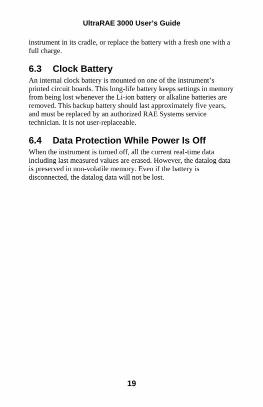
instrument in its cradle, or replace the battery with a fresh one with a full charge. 6.3 Clock Battery An internal clock battery is mounted on one of the instrument’s printed circuit boards. This long-life battery keeps settings in memory from being lost whenever the Li-ion battery or alkaline batteries are removed. This backup battery should last approximately five years, and must be replaced by an authorized RAE Systems service technician. It is not user-replaceable. 6.4 Data Protection While Power Is Off When the instrument is turned off, all the current real-time data including last measured values are erased. However, the datalog data is preserved in non-volatile memory. Even if the battery is disconnected, the datalog data will not be lost.
19
UltraRAE 3000 User’s Guide
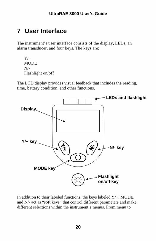
7 User Interface The instrument’s user interface consists of the display, LEDs, an alarm transducer, and four keys. The keys are:
Y/+ MODE N/- Flashlight on/off
The LCD display provides visual feedback that includes the reading, time, battery condition, and other functions.
LEDs and flashlight
Display
Y/+ key N/- key
MODE key
Flashlight on/off key
In addition to their labeled functions, the keys labeled Y/+, MODE, and N/- act as “soft keys” that control different parameters and make different selections within the instrument’s menus. From menu to
20
UltraRAE 3000 User’s Guide
menu, each key controls a different parameter or makes a different selection. Three panes along the bottom of the display are “mapped” to the keys. These change as menus change, but at all times the left pane corresponds to the [Y/+] key, the center pane corresponds to the [MODE] key, and the right pane corresponds to the [N/-] key. Here are three examples of different menus with the relationships of the keys clearly shown:
21
UltraRAE 3000 User’s Guide
7.1 Display The display shows the following information:
Gas info Tells the Correction Factor and type of
calibration gas Reading Concentration of gas as measured by the
instrument Calibration needed Indicates that calibration should be
performed Radio power Indicates whether radio connection is on or off Radio signal Indicates signal strength in 5-bar bargraph Battery Indicates battery level in 3 bars Pump Indicates that pump is working Datalog Indicates whether datalog is on or off Y/+ Y/+ key’s function for this screen MODE MODE key’s function for this screen N/- N/- key’s function for this screen
22
UltraRAE 3000 User’s Guide
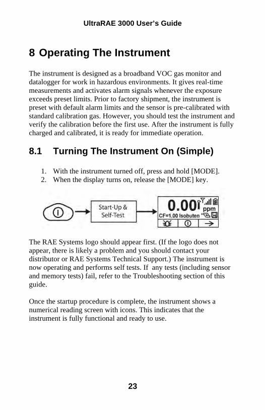
8 Operating The Instrument The instrument is designed as a broadband VOC gas monitor and datalogger for work in hazardous environments. It gives real-time measurements and activates alarm signals whenever the exposure exceeds preset limits. Prior to factory shipment, the instrument is preset with default alarm limits and the sensor is pre-calibrated with standard calibration gas. However, you should test the instrument and verify the calibration before the first use. After the instrument is fully charged and calibrated, it is ready for immediate operation. 8.1 Turning The Instrument On (Simple)
1. With the instrument turned off, press and hold [MODE]. 2. When the display turns on, release the [MODE] key.
The RAE Systems logo should appear first. (If the logo does not appear, there is likely a problem and you should contact your distributor or RAE Systems Technical Support.) The instrument is now operating and performs self tests. If any tests (including sensor and memory tests) fail, refer to the Troubleshooting section of this guide. Once the startup procedure is complete, the instrument shows a numerical reading screen with icons. This indicates that the instrument is fully functional and ready to use.
23
UltraRAE 3000 User’s Guide
8.2 Turning The Instrument On (Power On Zero) If your UltraRAE 3000 has been configured to perform a zero (fresh air) calibration upon startup, called Power On Zero, then the startup routine is interrupted so that you can perform a fresh air calibration. (See page 85 for details on turning this feature on or off.)
If you do not want to perform a zero calibration, press [MODE] to bypass it. If you start a zero calibration and want to abort it, press [N/-], and the calibration stops and the main display is shown. 8.3 Turning The Instrument Off
1. Press and hold the Mode key for 3 seconds. A 5-second countdown to shutoff begins.
2. When you see “Unit off...” release your finger from the [MODE] key. The instrument is now off.
Note: You must hold your finger on the key for the entire shutoff process. If you remove your finger from the key during the countdown, the shutoff operation is canceled and the instrument continues normal operation. 8.4 Operating The Built-In Flashlight The instrument has a built-in flashlight that helps you point the probe in dark places. Press the flashlight key to turn it on. Press it again to turn it off. Note: Using the flashlight for extended periods shortens the battery’s operating time before it needs recharging.
24
UltraRAE 3000 User’s Guide
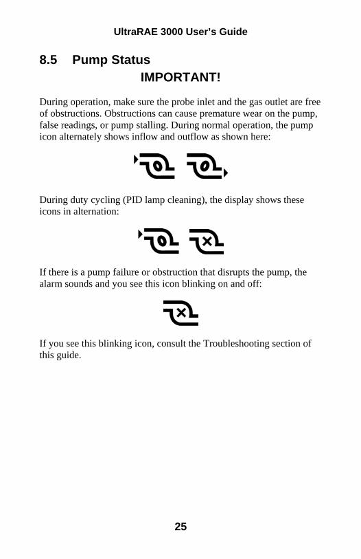
8.5 Pump Status IMPORTANT!
During operation, make sure the probe inlet and the gas outlet are free of obstructions. Obstructions can cause premature wear on the pump, false readings, or pump stalling. During normal operation, the pump icon alternately shows inflow and outflow as shown here:
During duty cycling (PID lamp cleaning), the display shows these icons in alternation:
If there is a pump failure or obstruction that disrupts the pump, the alarm sounds and you see this icon blinking on and off:
If you see this blinking icon, consult the Troubleshooting section of this guide.
25
UltraRAE 3000 User’s Guide
8.6 Calibration Status The instrument displays this icon if it requires calibration: Calibration is required (and indicated by this icon) if:
• The lamp type has been changed (for example, from 10.6 eV to 9.8 eV).
• The sensor module has been replaced. • It has been 30 days or more since the instrument was last
calibrated. • If you have changed the calibration gas type without
recalibrating the instrument.
26
ATTACHMENT D
Calibration for UltraRAE 3000 (User's Guide portion)
UltraRAE 3000 User’s Guide
19 Standard Two-Point Calibration (Zero & Span) The following diagram shows the instrument’s calibrations in Basic/Hygiene mode. Hygiene mode. N
ote:
Das
hed
line
indi
cate
s aut
omat
ic p
rogr
essi
on.
49
UltraRAE 3000 User’s Guide
19.1 Entering Calibration
1. Press and hold [MODE] and [N/-] until you see the Password screen.
2. In Basic User Level, you do not need a password to perform
calibrations. Instead of inputting a password, enter calibration by pressing [MODE]. Note: If you inadvertently press [Y/+] and change any of the numbers, simply press [MODE] and you will be directed to the calibration menu.
The Calibration screen is now visible with Zero Calibration highlighted.
These are your options:
• Press [Y/+] to select the highlighted calibration (Zero Calib or Span Calib).
• Press [MODE] to exit calibration and return to the main display and resume measurement.
• Press [N/-] to toggle the highlighted calibration type.
50
UltraRAE 3000 User’s Guide
19.2 Zero (Fresh Air) Calibration This procedure determines the zero point of the sensor calibration curve. To perform a fresh air calibration, use the calibration adapter to connect the instrument to a “fresh” air source such as from a cylinder or Tedlar bag (optional accessory). The “fresh” air is clean, dry air without organic impurities and an oxygen value of 20.9%. If such an air cylinder is not available, any clean ambient air without detectable contaminants or a charcoal filter can be used.
At the Zero Calibration menu, you can proceed to perform a Zero calibration or bypass Zero calibration and perform a Span calibration. You may also go back to the initial Calibration menu if you want to exit calibration.
• Press [Y/+] to start calibration. • Press [MODE] to quit and return to the main calibration
display. If you have pressed [Y/+] to enter Zero calibration, then you will see this message:
1. Turn on your Zero calibration gas. 2. Press [Y/+] to start calibration.
Note: At this point, you may press [MODE] if you decide that you do not want to initiate calibration. This will take you directly to the Calibration menu, highlighted for Span calibration.
51
UltraRAE 3000 User’s Guide
3. Zero calibration starts a 30-second countdown and displays this message:
Zeroing... During the zeroing process, the instrument performs the Zero calibration automatically and does not require any action on your part. Note: To abort the zeroing process at any time and proceed to Span calibration, press [N/-] at any time while zeroing is being performed. You will see a confirmation message that says “Zero aborted!” and then the Span calibration menu appears. When Zero calibration is complete, you see this message: Zeroing is done! Reading = 0.0 ppm The instrument will then show the Calibration menu on its display, with Span Calib highlighted. 19.3 Span Calibration This procedure determines the second point of the sensor calibration curve for the sensor. A cylinder of standard reference gas (span gas) fitted with a 500 cc/min. flow-limiting regulator or a flow-matching regulator is the simplest way to perform this procedure. Choose the 500 cc/min. regulator only if the flow rate matches or slightly exceeds the flow rate of the instrument pump. Alternatively, the span gas can first be filled into a Tedlar bag or delivered through a demand-flow regulator. Connect the calibration adapter to the inlet port of the instrument, and connect the tubing to the regulator or Tedlar bag.
Another alternative is to use a regulator with >500 cc/min flow but allow the excess flow to escape through a T or an open tube. In the latter method, the span gas flows out through an open tube slightly wider than the probe, and the probe is inserted into the calibration tube.
52
UltraRAE 3000 User’s Guide
At the Span Calibration menu, you perform a Span calibration. You may also go back to the Zero calibration menu or to the initial Calibration menu if you want to exit calibration.
• Press [Y/+] to enter Span calibration. • Press [N/-] to skip Span calibration and return to Zero
calibration. • Press [MODE] to exit Span calibration and return to the top
calibration menu. If you have pressed [Y/+] to enter Span calibration, then you will see the name of your Span gas (the default is isobutylene) and the span value in parts per million (ppm).
IMPORTANT! If you are using the UltraRAE 3000 to test for benzene, it is recommended that you calibrate with 5 ppm benzene calibration gas from RAE Systems. You will also see this message that prompts you:
1. Turn on your span calibration gas. 2. Press [Y/+] to initiate calibration.
Note: You may press [MODE] if you decide that you do not want to initiate calibration. This will abort the span calibration and take you directly to the Calibration menu for Zero calibration.
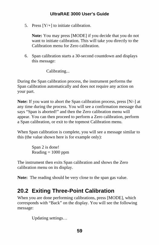
3. Span calibration starts and displays this message: Calibrating...
53
UltraRAE 3000 User’s Guide
During the Span calibration process, there is a 30-second countdown and the instrument performs the Span calibration automatically. It requires no actions on your part. Note: If you want to abort the Span calibration process, press [N/-] at any time during the process. You will see a confirmation message that says “Span is aborted!” and then the Zero calibration menu appears. You can then proceed to perform a Zero calibration, perform a Span calibration, or exit to the topmost Calibration menu. When Span calibration is complete, you see a message similar to this (the value is an example only): Span 1 is done! Reading = 100.0 ppm The instrument then exits Span calibration and shows the Zero calibration menu on its display. Note: The reading should be very close to the span gas value.
54
UltraRAE 3000 User’s Guide
19.4 Exiting Two-Point Calibration In Basic User Level When you are done performing calibrations, press [MODE], which corresponds with “Back” on the display. You will see the following message:
Updating settings… The instrument updates its settings and then returns to the main display. It begins or resumes monitoring.
55
UltraRAE 3000 User’s Guide
20 Three-Point Calibration For enhanced accuracy, it is possible to perform a second Span calibration in addition to the Zero and Span calibrations outlined in the previous section. Your instrument first must be set to allow this third calibration. This requires using ProRAE Studio software and a PC, as well as a higher concentration of calibration gas. Note: Once the third calibration is set, you do not need to use ProRAE Studio to allow future 3-point calibrations. Also, you can only disable 3-point calibration capability by using ProRAE Studio again. Perform the Zero and Span calibrations. After the first Span calibration (Span 1) is completed, the display a second Span calibration (Span 2) can be performed. The process is identical to the first calibration. As in the Span 1 calibration, you may exit and return to the Zero calibration screen if you choose not to perform this calibration or to abort it.
56
UltraRAE 3000 User’s Guide
N
ote:
Das
hed
line
indi
cate
s aut
omat
ic p
rogr
essi
on.
57
UltraRAE 3000 User’s Guide
20.1 Span 2 Calibration A cylinder of standard reference gas (span gas) fitted with a 500 cc/min. flow-limiting regulator or a flow-matching regulator is the simplest way to perform this procedure. Note: This gas should be of a higher concentration than the gas used for Span 1 calibration. Choose the 500 cc/min. regulator only if the flow rate matches or slightly exceeds the flow rate of the instrument pump. Alternatively, the span gas can first be filled into a Tedlar bag or delivered through a demand-flow regulator. Connect the calibration adapter to the inlet port of the instrument, and connect the tubing to the regulator or Tedlar bag.
Another alternative is to use a regulator with >500 cc/min flow but allow the excess flow to escape through a T or an open tube. In the latter method, the span gas flows out through an open tube slightly wider than the probe, and the probe is inserted into the calibration tube.
At the Span Calibration menu, you perform a Span calibration. You may also go back to the Zero calibration menu or to the initial Calibration menu if you want to exit calibration.
• Press [Y/+] to enter Span 2 calibration. • Press [N/-] to skip Span calibration and return to Zero
calibration. • Press [MODE] to exit Span calibration and return to the top
calibration menu. If you have pressed [Y/+] to enter Span calibration, then you will see the name of your Span gas (the default is isobutylene) and the span value in parts per million (ppm). You will also see this message that prompts you: Please apply gas...
4. Turn on your span calibration gas.
58
UltraRAE 3000 User’s Guide
5. Press [Y/+] to initiate calibration. Note: You may press [MODE] if you decide that you do not want to initiate calibration. This will take you directly to the Calibration menu for Zero calibration.
6. Span calibration starts a 30-second countdown and displays this message:
Calibrating... During the Span calibration process, the instrument performs the Span calibration automatically and does not require any action on your part. Note: If you want to abort the Span calibration process, press [N/-] at any time during the process. You will see a confirmation message that says “Span is aborted!” and then the Zero calibration menu will appear. You can then proceed to perform a Zero calibration, perform a Span calibration, or exit to the topmost Calibration menu. When Span calibration is complete, you will see a message similar to this (the value shown here is for example only): Span 2 is done! Reading = 1000 ppm The instrument then exits Span calibration and shows the Zero calibration menu on its display. Note: The reading should be very close to the span gas value.
20.2 Exiting Three-Point Calibration When you are done performing calibrations, press [MODE], which corresponds with “Back” on the display. You will see the following message:
Updating settings…
59
UltraRAE 3000 User’s Guide
The instrument updates its settings and then returns to the main display. It begins or resumes monitoring.
21 Programming Mode Programming Mode can be entered from either Hygiene Mode or Search Mode. If the current user mode is Basic, you must provide a 4-digit password to enter. 21.1 Entering Programming Mode 1. Press and hold [MODE] and [N/-] until you see the Password screen.
2. Input the 4-digit password: • Increase the number from 0 through 9 by pressing [Y/+]. • Step from digit to digit using [N/-]. • Press [MODE] when you are done.
If you make a mistake, you can cycle through the digits by pressing [N/-] and then using [Y/+] to change the number in each position. Note: The default password is 0000.
60
UltraRAE 3000 User’s Guide
When you have successfully entered Programming Mode, you see this screen:
Note: The password can only be changed by connecting the instrument to a PC running ProRAE Studio software. Follow the instructions in ProRAE Studio to change it.The Calibration label is shown and its icon is highlighted, but you can press [N/-] to step from one programming menu to the next, with the name of the menu shown at the top of the display and the corresponding icon highlighted. As you repeatedly press [N/-], the selection moves from left to right, and you see these screens:
Note: When you reach Monitor Setup and press [N/-], the menu cycles back to Calibration.
22 Programming Mode Menus The Programming Mode allows anyone with the password to change the instrument’s settings, calibrate the instrument, modify the sensor configuration, enter user information, etc. Programming Mode has five menus. Each menu includes several sub-menus to perform additional programming functions.
61
ATTACHMENT E
Jerome J605 User Manual (portion)
AZI P/N 700-0108-D Last update November 2012
USER MANUAL
JEROME® J605 HYDROGEN SULFIDE ANALYZER
November 2012
Firmware v1.2X
ARIZONA INSTRUMENT LLC 3375 N Delaware Street | Chandler, AZ 85225 USA
AZI Customer Service 800-528-7411 or 602-470-1414 Page 4 of 57
1. UNPACKING THE INSTRUMENT This manual contains details that will optimize the results and the life of your instrument. Read and refer to the manual for complete details on operation, maintenance and troubleshooting, special voltage inputs and data output. The Jerome® J605 is easy to operate and ready for use upon receipt from the factory. • Remove the instrument from the packing material.
Retain all packaging materials for any future shipment of the instrument.
If the instrument is returned to AZI for any reason, it must be placed in the original packaging materials that have been tested and
proven to be effective protection during shipment.
• Call AZI Customer Service at 800-528-7411 or 602-470-1414 or go to the AZI website www.azic.com for Return Material Authorization (RMA) information prior to returning an instrument.
• Boxes and packing materials for all shipments are available from AZI. • Pack the Jerome® instrument only in a Jerome® shipping container.
AZI WILL NOT BE RESPONSIBLE FOR SHIPPING DAMAGE. IF YOU RETURN THE INSTRUMENT IMPROPERLY PACKAGED OR
SHIPPED, YOU SHOULD INSURE IT FOR FULL VALUE.
• Check for any damage and confirm receipt of all parts on your packing list. Contact Arizona Instrument Customer Service at (800) 528-7411 or (602) 470-1414 if you have any questions.
• Press the I/O button. The display will light up and show instrument serial number and software revision. If necessary, press ESC to clear any calibration
reminders. Call AZI Customer Service or e-mail [email protected], to schedule instrument calibration.
• The digital meter displays 0.000 ppm (or 0.00 ppb). • Look at the battery icon in the top center of the display
to determine the current battery level. If the battery icon is empty and flashing, recharge
the battery. See page 28.
• The included AC power supply/charger can utilize 110V or 220V AC power, and it is not necessary to manually select the input voltage.
• The J605 contains an auto-resetting fuse that does not require care, maintenance or replacement by the user.
AZI Customer Service 800-528-7411 or 602-470-1414 Page 5 of 57
• Perform a sensor regeneration by following these steps: Connect the AC power supply/charger between the matching (DIN) connector on the back
of the J605 and an AC power outlet or connect the external battery pack to the back of the J605.
If the J605 is turned off, press the I/O power button to turn the instrument on. Press the RIGHT arrow button (►) to enter the main menu. Press the DOWN arrow button (▼) to move the cursor to Regen. Press the RIGHT arrow button (►) to select Regen from the menu. Press the ENTER/START button on the keypad to select Regen Now from the Regen
menu. The instrument will now begin a 45-minute regeneration cycle, indicated by
“Regeneration in Progress” on the display. Do not interrupt this cycle. For a complete description of this process, see page 23.
If any error message appears on the display, see the J605 TROUBLESHOOTING section beginning on page 37.
• Ensure the instrument has been powered on for at least five (5) minutes prior to sampling. • The instrument is now ready to sample. • The instrument is designed for ambient air monitoring.
• The instrument is not explosion proof.
• Press the SAMPLE BUTTON at the end of the handle of the J605 to start a sampling cycle.
• When the instrument measures hydrogen sulfide, the 0.000 ppm (or 0.00 ppb) display will be replaced with a value.
• To ensure the input to the instrument contains no hydrogen sulfide or mercaptans, install a Zero Air Filter (AZI P/N Z2600 3905) in the intake of the instrument. The Zero Air Filter cleans the air sample and should produce sample readings of 0.000 ppm (or 0.00 ppb). Therefore, use the filter to: Equilibrate the instrument to temperatures that are higher or lower than the instrument.
Sample with the filter installed until the reading is 0.000 ppm (or 0.00 ppb). Identify contamination within the instrument. Confirm the presence of hydrogen sulfide when readings are elevated. Install the Zero Air
Filter and verify that the readings go down with the filter installed. • Perform sensor regeneration before each day’s use. • Perform another sensor regeneration after each day’s use. • During periods of storage or inactivity, perform sensor regeneration every 30 days.
Call AZI Customer Service, at (800) 528-7411 or (602) 470-1414 if you have any questions. If you prefer, you may send e-mail to [email protected].
WARNING DO NOT allow the probe or the instrument’s intake to be exposed to any liquid. DO NOT obstruct the intake or exhaust ports of the J605, as this could cause errors in readings and damage to the flow control system.
AZI Customer Service 800-528-7411 or 602-470-1414 Page 6 of 57
2. INTRODUCTION The Jerome® J605 Hydrogen Sulfide Analyzer is an ambient air analyzer with a range of 3 parts per billion (ppb) to 10 parts per million hydrogen sulfide (ppm H2S). Readings of 100 ppb or less are displayed in units of ppb, and readings above 100 ppb (0.100 ppm) are displayed in ppm. Readings of zero are displayed as 0.000 ppm or 0.00 ppb depending on the Range in use.
CAUTION: The Jerome® J605 is for gaseous vapor use only.
DO NOT allow the probe or the instrument's intake to be exposed to any liquid, dust
or other foreign material. The J605 is designed to be easy to operate for quick and accurate analysis of hydrogen sulfide levels. It has few maintenance requirements. However, please take a moment to read this manual before attempting operation. If you have any questions about your application or operation, please call AZI Customer Service at (800) 528-7411 or (602) 470-1414 or e-mail [email protected] for assistance.
J605 Features
• Accurate analysis of hydrogen sulfide concentrations in seconds. • 3 ½ inch (9 cm) backlit display, showing everything you need to be confident in the
instrument, including 5/8 inch (1.6 cm) tall character readout, battery charge indicator, and sensor saturation percentage.
• Microprocessor ensures a linear response throughout the entire range of the sensor. • Inherently stable gold film sensor. • Wide detection range allows for multiple applications. • Survey mode for rapid source detection of hydrogen sulfide concentrations. • Rechargeable internal battery pack for portability. • Easy to understand diagnostic and error detection. • Auto zero bridge adjustment. • Updated electronics including 24-bit a/d conversion, and on-board storage for 20,000
samples. • Controlled temperature film heat ensures the sensor removes all hydrogen sulfide and
returns to its original state. • The Jerome® J605 can be operated for 18 hours from the internal 12V battery or it can
be operated using the external AC power supply/charger.
Accessories and Maintenance Parts The Accessories and optional items available to support the J605 are listed and pictured beginning on page 40.
AZI Customer Service 800-528-7411 or 602-470-1414 Page 11 of 57
Zero Air Filter (AZI P/N Z2600 3905) The Zero Air Filter (AZI P/N Z2600 3905) removes hydrogen sulfide, mercury vapor and mercaptans from the air sample. Readings with the filter installed should be near 0.000 ppm (or 0.00 ppb). For maximum accuracy, wait 15 seconds between samples to allow the sensor to restabilize. Because air that is cooler than the instrument will cause low readings and warmer air will cause higher readings, the Zero Air Filter should be used to equilibrate the instrument to ambient air. Repeated sampling with clean air will not cause saturation of the gold film sensor but will equalize temperatures faster to allow accurate analysis to begin sooner. For maximum accuracy, wait 15 seconds between samples to allow the sensor to restabilize. The Zero Air Filter can also be used to identify contamination within the instrument. If the readings do not reduce to near 0.000 ppm with the filter installed, contamination should be suspected. If the readings do drop to near 0.000 ppm with the filter installed but elevate with the filter removed, the presence of hydrogen sulfide at the sampled location is confirmed. Again, for maximum accuracy, wait 15 seconds between samples to allow the sensor to restabilize. The Zero Air Filter should be inserted into the intake of the instrument when running the instrument Warm-up. For more information on the use of the Zero Air Filter, contact customer service at 1-800-528-7411 or 1-602-470-1414.
AZI Customer Service 800-528-7411 or 602-470-1414 Page 12 of 57
5. INSTRUMENT OPERATION
J605 Main Screen Display The J605 Main Screen is depicted below, followed by explanations of the labeled items.
SYSTEM TIME – As set in the SYSTEM menu. (See SYSTEM menu on page 20) BATTERY – Indicates current charge level and charging status (See Charging Internal Battery
on page 28) SOUND ICON – Indicates if the audible alarm is turned on or muted, as set in the SYSTEM
menu. (See SYSTEM menu on page 20). SYSTEM DATE – As set in the SYSTEM menu. (See SYSTEM menu on page 20) SENSOR SATURATION METER – Graphically indicates the hydrogen sulfide saturation level
of the J605 sensor. (See REGEN menu on page 17). USB ICON – Indicates proper functioning of USB ports, and flashes during USB transmission of
data. (See Retrieving Data on page 29). If the USB icon is not present, this option is not activated. Contact your AZI Sales Representative for details on the USB option.
RANGE – Indicates in which Range the J605 is set to sample: 0, 1, 2 or A (Auto-range), as set in the SAMPLE menu. (See Range in SAMPLE menu on page 15).
AUTO SAMPLING INDICATOR – Indicates if the J605 is set to sample automatically at regular intervals, as set in Sample Mode in the SAMPLE menu. (See SAMPLE menu on page 15).
HYDROGEN SULFIDE READING – The hydrogen sulfide concentration detected by the J605, in the units indicated.
UNITS – Units for the hydrogen sulfide reading: parts per million (ppm) or parts per billion (ppb), depending on the Range in use and the sample concentration detected. Readings of zero are displayed as 0.000 ppm or 0.00 ppb, depending on the Range being used.
AVAILABLE KEYPAD COMMANDS – The bottom line of the screen indicates the currently available keypad commands. From the main screen, as shown here, the Main Menu can be accessed using the ► key.
AZI Customer Service 800-528-7411 or 602-470-1414 Page 13 of 57
J605 Back Panel Connections
The above-labeled connections are available from the back panel of the J605. If the USB option has not been activated, the USB ports will not be present. Contact your AZI Sales Representative for information on the USB option. POWER CONNECTOR – Connect the supplied AC power supply/charger here to power the instrument or recharge the internal battery, or connect the optional external battery pack (AZI P/N: 990-0214) or the optional car accessory cable (AZI P/N: 200-0170) here to provide power to the instrument. USB TYPE “A” PORTS – The USB Type “A” ports are used to connect a USB printer or USB memory drive for printing or saving sample data or to connect a USB keyboard for menu navigation or data entry. The two ports are identical, and either can be used. For more information, see DATA menu on page 18. USB TYPE “B” PORT – The USB Type “B” port is used to connect the J605 directly to the USB port of a computer, using the included USB A to B cable (AZI P/N: 200-0165). For more information see DATA menu on page 18. DB25 CONNECTOR – There are multiple specialized uses for the DB25 connector. See Instrument I/O Interface on page 30 for more information. NOTE: This is not a printer port. EXHAUST PORT – After sampling, the sampled air is cleaned of any hydrogen sulfide and expelled from the exhaust port on the back of the J605.
AZI Customer Service 800-528-7411 or 602-470-1414 Page 14 of 57
J605 User Interface Main Menu Structure
NOTE: The main menu also contains a selection labeled “Factory.” This option is for AZI factory use only and is not accessible by the end user.
AZI Customer Service 800-528-7411 or 602-470-1414 Page 15 of 57
A USB keyboard (AZI P/N: 990-0230) can be used to navigate the menu system and for data entry for items such as Location Names. Connect the USB keyboard to one of the two USB Type “A” ports on the back of the instrument. Either upper or lower case characters may be entered when using a USB keyboard, while only upper case letters are available from the J605 keypad. The keyboard arrow keys can be used to navigate the menu system.
SAMPLE menu SAMPLE MODE The Sample Mode setting provides the choice between auto-sampling and manual sampling. For normal use, use manual sampling, which is the instrument default setting. If auto-sampling is selected, the instrument will automatically sample at the interval set in SET SAMPLE INTERVAL (below) without monitoring or attendance by the user. Use the ▲and ▼arrows to toggle between Manual and Auto, and use ENTER/START to save the selection. Use the ESC key to exit without saving changes. If auto-sampling is selected, the word Auto will appear below the system date on the instrument’s main screen. RANGE Three different ranges and an Auto-ranging function are available in the J605. If the approximate value of the expected H2S concentration is known, the instrument can be set into that specific range prior to sampling (0, 1, or 2). If the expected H2S concentration is not known, Auto-ranging can be used instead, and the J605 will test each sample in each range before displaying the concentration. Using Auto-ranging results in longer test times, however accuracy is not affected. The selected range also determines what units the J605 will use to display the results. The three ranges and their default display units (ppb or ppm) are shown below:
RANGE CONCENTRATION 0 3 to 100 ppb 1 0.10 to 1.0 ppm 2 1.0 to 10.0 ppm
The range can be set or Auto-ranging can be toggled on or off by selecting Range from the SAMPLE menu. Use ▲ and ▼ to scroll through the ranges 0, 1, 2 and Auto, and press ENTER/START to make a selection. Press ESC to exit without saving changes. The selected range will be displayed on the main screen as a number (0, 1, 2) or as an A for Auto-ranging. See J605 Main Screen Display on page 12 for the location of the Range indicator. SET SAMPLE INTERVAL If auto-sampling is being used (as set in SAMPLE MODE above), the sample interval determines how often the J605 will automatically take samples. Use the ▲and ▼arrow keys to scroll through the available sample intervals of 1, 2, 5, 10, 15, 30, 45, 60, 90 and 120 minutes, and use ENTER/START to save the selected interval. Use the ESC key to exit without saving changes. The sample intervals refer to specific times on the instrument clock as measured in whole multiples of the selected interval. For example, selecting a 10-minute sample interval will result
AZI Customer Service 800-528-7411 or 602-470-1414 Page 16 of 57
in samples being taken on the hour, 10 minutes after the hour, 20 minutes after the hour, etc., not every ten minutes from when auto-sampling is initiated. Refer to the chart below for examples of how these intervals work. The Main Screen must be displayed for autosampling takes place, and autosampling will start when the clock reads :00 seconds. Interval Samples on the: Examples: 1 minute 1-minute marks 12:00, 12:01, 12:02, 12:03, 12:04, 12:05, 12:06, etc.
2 minutes 2-minute marks 12:00, 12:02, 12:04, 12:06, 12:08, 12:10, 12:12, etc.
5 minutes 5-minute marks 12:00, 12:05, 12:10, 12:15, 12:20, 12:25, 12:30, etc.
10 minutes 10-minute marks 12:00, 12:10, 12:20, 12:30, 12:40, 12:50, 1:00, etc.
90 minutes Times that are an even 90 minutes from midnight or noon
12:00, 1:30, 3:00, 4:30, 6:00, 7:30, 9:00, 10:30, etc.
120 minutes Times that are an even 120 minutes from midnight or noon
12:00, 2:00, 4:00, 6:00, 8:00, 10:00, etc.
SET LOCATION NAME Up to 80 unique location presets are available using the J605. This feature is useful if sampling is done in multiple locations and there is a need to record which readings came from which locations. Use the ▲and ▼arrows to scroll through the list of 80 presets until the location to be edited is highlighted. Press ENTER/START to begin editing the name of the selected location. Use the ▲and ▼arrows to scroll through the available alphanumeric characters and punctuation. When the desired character is displayed, use the ► arrow to move to the next character field. If a mistake is made, the ◄ arrow can be used to return to the previous character. When the location has been named as desired, press ENTER/START to save the location name, and return to the list of locations. To select an existing location from the list for the samples to be taken, use the ▲and ▼arrows to scroll to the desired location, and press ENTER/START twice. Note the asterisk (*) located to the left of the currently selected location. The selected location name will be stored with the sample data for all samples taken until a different location is selected instead. Use ESC to return to the sample menu. See Retrieving Data on page 29 for more info. SURVEY MODE Highlight SURVEY MODE in the SAMPLE menu and press ENTER/START to begin immediate sampling in survey mode. In survey mode, after an initial four-second pause to purge the flow system, the J605 will sample continuously. For complete information on survey mode, see Survey Mode on page 25.
AZI Customer Service 800-528-7411 or 602-470-1414 Page 17 of 57
REGEN menu The sensor saturation meter on the main screen (to the right of s. sat) indicates the current level of saturation of the sensor with hydrogen sulfide. When the sensor becomes saturated with hydrogen sulfide, as indicated by the sensor saturation meter, a regeneration (regen) must be performed on the sensor to release the accumulated hydrogen sulfide, before additional samples can be taken. See Sensor Regeneration on page 23 for more information on the regeneration procedure. The AC power supply/charger or the external battery pack must be plugged into the back of the instrument before a regeneration can be performed. The following options are available from the REGEN menu: REGEN NOW Connect external power to the instrument before performing a regeneration. Highlighting REGEN NOW and pressing ENTER/START will immediately start the sensor regeneration process. Do not disconnect external power during the regeneration. WARMUP To ensure maximum accuracy when sampling at levels less than 10 ppb, the J605 must be warmed up with the Zero Air Filter in the intake, at the location to be sampled. To run the warm-up, insert the Zero Air Filter in the intake, highlight WARMUP and press ENTER/START. While warming up, the pump will run and the J605 will display a 5-minute countdown. When the warm-up finishes, remove the Zero Air Filter and begin normal sampling. If the J605 is idle for more than 20 minutes, another warm-up is required to maintain maximum accuracy at these low levels. SET INTERVAL If auto-sampling is being used (as set in SAMPLE MODE above), the J605 can be configured to automatically perform sensor regenerations at a predetermined interval. Use the ▲and ▼arrows to scroll through the available intervals of 6, 12, 24, and 48 hours, and press ENTER/START to save the selected interval. The J605 will now automatically perform a sample followed by a
Clean/Regenerated Sensor
Partially Saturated Sensor
Saturated Sensor – Regeneration Required
AZI Customer Service 800-528-7411 or 602-470-1414 Page 18 of 57
regeneration every 6, 12, 24, or 48 hours as selected, starting at the time set in SET HOUR below. Use ESC to exit without saving. SET HOUR Use the ▲and ▼arrow keys to select the hour of the day (using a 24-hr clock) to start regeneration. Press ENTER/START to save the setting. At the time set, if auto-sampling is being used, the J605 will automatically take one sample and then perform a regeneration. This process will repeat at the interval indicated in SET INTERVAL above. Use ESC to exit without saving. NOTE: If the sensor is saturated and a regeneration cycle is performed and completed before the set hour, the instrument will perform another regeneration at the set hour. However, if the regeneration cycle does not complete prior to the set hour, the regeneration at the set hour will be skipped.
DATA menu Sample data can be stored within the instrument, up to a maximum of twenty thousand (20,000) data points. On instruments that have the USB Communications option, in addition to viewing the sample data on the instrument, data can be retrieved from the instrument in one of three ways:
1. SEND TO PC 2. SAVE TO USB MEMORY DRIVE 3. PRINT DIRECTLY TO AN AZI APPROVED PRINTER (AZI P/N: Y990-0098)
The presence of the USB icon on the main screen indicates that the Communications option has been purchased and that the USB ports are functioning properly. The USB icon will flash during data transmission. See J605 Main Screen Display on page 12 for the location of the USB icon. The data is stored in non-volatile memory and will not be affected if the battery is changed or disconnected. VIEW STORED DATA Select VIEW STORED DATA to view previous sample and regeneration history on the screen of the J605. The Location Name (if specified) corresponding to the data is displayed at the top of the screen and three sample values at a time are displayed at the bottom of the screen, along with the time and date the sample was taken. The most recent sample is displayed at the top of the list, and regenerations are indicated by the word “Regen” instead of a sample value. Use the ▲ and ▼ arrow keys to scroll through the data. If Location Names are used, the Location Name displayed will automatically update during scrolling to reflect the sampling location of the data being displayed. The J605 will beep-beep upon reaching the end of the list. After viewing the data, press ESC to exit and return to the DATA menu. On instruments that have the USB Communications option, all of the data is accessible from the VIEW STORED DATA menu selection. On instruments that do not have the USB Communications option, only the previous two samples can be accessed and displayed.
AZI Customer Service 800-528-7411 or 602-470-1414 Page 19 of 57
SAVE TO USB DRIVE Before selecting SAVE TO USB DRIVE, connect the target USB memory drive to either USB TYPE “A” PORT on the back panel of the J605. When ENTER/START is pressed, all of the stored data on the J605 will be transmitted to the target drive as a comma-delimited text file. See Retrieving Data on page 29 for more information.
NOTE: The J605 is NOT compatible with USB memory drives that have the U3 program pre-installed. Do not use USB memory drives that have the U3 program with the J605.
SEND TO PC Before using SEND TO PC, the USB driver must be installed on the target PC, and HyperTerminal must be configured on the target PC. The USB driver is on the CD with this operations manual and on the AZI website at www.azic.com. See APPENDIX A – USB/HYPERTERMINAL SETUP on page 45 for detailed instructions on installing the USB driver, configuring HyperTerminal, and downloading data from the J605. Once the target PC has been configured, connect the included USB A to B cable (AZI P/N: 200-0165) between the USB TYPE “B” PORT on the back panel of the J605 and the USB PORT of the target computer, and launch HyperTerminal. On the J605, with SEND TO PC highlighted, press ENTER/START, and all of the stored data on the J605 will be transmitted to the target computer as a comma-delimited text file. See Retrieving Data on page 29 for more information. PRINT DATA Before selecting PRINT DATA, connect an AZI printer (AZI P/N: Y990-0098) to either USB TYPE “A” PORT on the back panel of the J605 using the cable supplied with the printer. When ENTER/START is pressed, all of the stored data on the J605 will be printed on the attached printer. See Retrieving Data on page 29 for more information. VIEW MEMORY USAGE The J605 can store up to 20,000 data points. Selecting VIEW MEMORY USAGE will display what percentage of the data storage area is in use. Once the data memory is full, no additional data can be stored until the data on the instrument is deleted. If the memory is full, the J605 will continue to perform as expected, but it will indicate that the memory is full and no new sample data will be retained. The storage area can be cleared using DELETE DATA as described below. DELETE DATA Selecting DELETE DATA will delete all sample data stored on the J605. Prior to deletion, the J605 will prompt the user for confirmation as a precaution.
AZI Customer Service 800-528-7411 or 602-470-1414 Page 20 of 57
SYSTEM menu The SYSTEM menu is password protected to prevent unwanted or accidental changes to operating parameters. The default initial password is AZI, but should be changed to something unique if restricted access to the SYSTEM menu is desired. The password can be up to 10 characters long. When the SYSTEM menu is selected from the Main Menu, the J605 will prompt for the password. Input the password using ▲ and ▼ to change the alphanumeric character, and ► and ◄ to move between characters. Press ENTER/START to proceed after entering the password. The SYSTEM menu will remain unlocked until the instrument is powered off and back on. After the correct password is entered, the password can be changed using the CHANGE PASSWORD selection at the bottom of the SYSTEM menu. SET ALARM LEVELS When sampling, if the hydrogen sulfide level exceeds the selected alarm level, the word “ALARM” will flash on the J605 display. If the AUDIBLE ALARM is set ON, the J605 will also beep three times. Two different alarm levels can be set using this menu option. Use the ▲and ▼arrow keys to change the value of the blinking field, and the ► arrow to move to the next character in the alarm level setting. Typically, the high alarm is used for an industrial level, while the low alarm is set to a residential value. Use the A and B buttons to switch between the high and low alarm settings by pressing A to select the high alarm or B to select the low alarm. Once the alarm level has been set, press ENTER/START to select the highlighted alarm level as the current alarm level to be used. Upon returning to the SET ALARM LEVELS screen, there will be asterisk next to the currently selected alarm level (either high or low). It is recommended to set the alarm level higher than .003 ppm. The alarm can be muted using AUDIBLE ALARM ON/OFF in the SYSTEM menu. AUDIBLE ALARM ON/OFF Use the ▲and ▼arrow keys to toggle the audible alarm on or off, and use ENTER/START to save the desired setting. Press ESC to exit without saving changes. The main screen display has a sound icon that indicates if the alarm is currently turned on or muted. The action lines in front of the sound icon on the main screen will disappear when the audible alarm is muted. See J605 Main Screen Display on page 12 to locate the sound icon. DISPLAY MODE From the DISPLAY MODE screen, use the ▲and ▼arrow keys to toggle between Threshold and Scientific display modes, and press ENTER/START to save the setting. In Scientific display mode, the J605 displays the sample reading for every sample taken. In Threshold display mode, the sample reading must be within 85% of the set alarm level to be displayed. Results below 85% of the alarm level value will be displayed as 0.000 ppm or 0.00 ppb depending on the current Range selected. Use ESC to exit without saving. See SET ALARM LEVELS above to set Threshold limits.
AZI Customer Service 800-528-7411 or 602-470-1414 Page 21 of 57
VIEW SENSOR STATS Use VIEW SENSOR STATS to display the current saturation level of the sensor, the number of regenerations performed on the sensor, and the total number of samples read by the sensor. Press any key to exit the screen when finished. SET SYSTEM TIME The J605 maintains the system time using a 24-hr clock format. Use the ▲and ▼arrow keys to change the value in the field where the cursor is flashing. Use the ◄ and ► arrow keys to move between the two digits within the hour or minute fields, and use the A and B keys to switch between the hour and minute fields. Use ENTER/START to save the indicated time as the system time or ESC to exit without saving. SET SYSTEM DATE Use the ▲and ▼arrow keys to change the highlighted field, and the ◄ and ► arrow keys to move between characters within the day or year fields. Use the A and B keys to move between the day, month, and year fields. Press ENTER/START to save the system date or ESC to exit without saving. RUN DIAGNOSTICS Selecting RUN DIAGNOSTICS will start the J605’s self-diagnostic procedure. As the instrument proceeds through each diagnostic check, follow the on-screen prompts, and the instrument will display the specific check being performed and the pass/fail result of the check. If the check is not applicable to the current configuration of the instrument, the result field will be blank instead of indicating pass or fail. • After viewing each result, press any key (except I/O or ESC) to move to the next diagnostic
check. (I/O should not be used during the diagnostics because I/O will power off the instrument and ESC should only be used when specifically indicated by the instrument.)
• When testing the keypad, follow the on-screen prompts to press each of the keys in turn. The J605 will not indicate a pass/fail for this test. Instead, if all of the keys work and the instrument proceeds to the next diagnostic test, the keypad diagnostic has passed.
• If the 4-20mA output function of the J605 is not in use, press ENTER/START to cycle through the 4, 8, 12, 16 and 20mA checks in the diagnostic routine. If the 4-20mA output is in use, the diagnostics can be used to verify proper operation. Refer to 4-20mA Output on page 30 for more information.
After the last diagnostic result has been displayed, the instrument will display “Done,” and pressing any key will return to the main screen of the J605. SET CONTRAST The display contrast can be set from 0 (highest contrast) to 127 (least contrast) by using ▲ and ▼ to adjust the contrast. By default, ▲ and ▼will adjust the contrast in increments of 1 unit. Press B to switch to a coarse adjustment of 10 units for each press of ▲ or ▼. Press A to switch back to the default fine adjustment mode. Press ENTER/START to save the contrast setting and exit. CHANGE PASSWORD Select CHANGE PASSWORD to change the password on the SYSTEM menu. Use ▲ and ▼ to change each alphanumeric character, and ► and ◄ to move between characters. Press ENTER/START to proceed after entering the password.
AZI Customer Service 800-528-7411 or 602-470-1414 Page 22 of 57
Daily Operations Before each day's use of the Jerome® J605, perform the following steps to verify proper instrument operation: • Press the power I/O button to turn the instrument on.
The display will light up and show instrument serial number and software revision. If necessary, press ESC to clear any calibration reminders. Call AZI Customer
Service at 800-528-7411 or 602-470-1414, or e-mail [email protected], to schedule instrument calibration.
The digital meter displays 0.000 ppm (or 0.00 ppb, depending on what Range is currently selected).
Check the battery level as indicated by the battery icon at the top center of the instrument display. If the battery meter is empty and flashing, refer to Charging Internal Battery on
page 28. If the battery meter is not empty, but is flashing, then the instrument is currently
charging the battery. When the instrument is plugged in and powered off, the display will stay active
and indicate “Charging.” To ensure the instrument's electronics have stabilized, allow a 5-minute warm up
before beginning the next step. • Perform sensor regeneration. Refer to Sensor Regeneration on page 23 for the procedure. • Ensure the instrument has been powered on for at least five (5) minutes prior to sampling. • Use the Zero Air Filter to equilibrate the instrument to ambient air temperature.
Install the Zero Air Filter in the instrument’s intake. Sample repeatedly every 15 seconds until the readings stabilize, then remove the Zero
Air Filter.
• Press the SAMPLE button (at the end of the handle). • At the end of the sampling cycle, read the digital meter.
The number shown on the digital meter is the hydrogen sulfide concentration in ppb or ppm as appropriate.
This sampled hydrogen sulfide value remains on the display until the next sample is taken.
The digital meter automatically re-zeroes at the start of each sample. • At the end of each day's use, perform sensor regeneration as described in the next section.
DO NOT ALLOW HYDROGEN SULFIDE TO STAY ON THE GOLD FILM SENSOR OVERNIGHT.
NOTE: For levels less than 10 ppb, it is necessary to run a warm-up routine before sampling. To initiate the automatic five minute warm-up, install a Zero Air Filter (AZI P/N Z2600 3905)
in the intake, and select Warmup from the REGEN menu. For levels of 10 ppb and above, the warm-up routine is not necessary.
AZI Customer Service 800-528-7411 or 602-470-1414 Page 23 of 57
Sensor Regeneration Sensor regeneration is needed to clean the J605 sensor of any accumulated hydrogen sulfide and to prolong the life of the sensor. This simple procedure should be done:
• At the beginning of the day on which the instrument is to be used. • During the day when the sensor becomes saturated. • At the end of the day before storing the instrument. • At a minimum of 30-day intervals while the instrument is in storage.
To perform sensor regeneration:
• Plug the AC power supply/charger or the external battery pack into the back of the instrument.
• Press the power I/O button to power on the instrument. • If necessary, press ESC to clear any calibration reminders. Call AZI Customer Service at
800-528-7411 or 602-470-1414, or e-mail [email protected], to schedule instrument calibration.
• From the Main Screen, press the RIGHT arrow button (►) to enter the main menu. • Press the DOWN arrow button (▼) to move the cursor to Regen. • Press the RIGHT arrow button (►) to select Regen from the menu. • Press the ENTER/START button on the keypad to select Regen Now from the Regen
menu. The instrument will begin a 45-minute regeneration cycle, indicated by “Regeneration
in Progress” on the display. Do not interrupt this cycle. If any error message appears on the display, see the J605 TROUBLESHOOTING
section beginning on page 37. • The LCD screen displays “Regeneration in Progress” for the duration of the 45-minute
cycle and displays a countdown timer as well once the instrument enters the cooling process of the regeneration. When the cycle is completed, the instrument returns to the main screen.
DO NOT INTERRUPT THIS CYCLE. Wait until the cycle is completed before continuing with the next step.
If the regeneration is interrupted, restart the regeneration process.
• The instrument can be used immediately following the sensor regeneration if necessary. • The Jerome® J605 is ready for sampling.
CAUTION: The Jerome® J605 is intended for gaseous vapor use only.
DO NOT allow the probe or the instrument's intake to be exposed to liquids, dust or other foreign material. Moisture or liquids drawn
into the instrument can damage the sensor and flow system.
AZI Customer Service 800-528-7411 or 602-470-1414 Page 24 of 57
Sample Mode This mode, used for standard operation, produces optimum accuracy with the Jerome® J605. See JEROME® J605 TECHNICAL SPECIFICATIONS on page 8 for the accuracy specifications. • Press the power I/O button. The display will light up and briefly show the instrument serial
number and software revision. If necessary, press ESC to clear any calibration reminders. Next, the digital meter displays 0.000 ppm (or 0.00 ppb, depending on the selected
Range). If the battery meter is empty and flashing, recharge the battery. See the section Charging Internal Battery on page 28.
• To ensure the instrument's electronics have stabilized, allow a 5-minute warm up before beginning the next step.
• Press the SAMPLE button (located at the end of the handle). • At the end of the sample cycle, read the digital meter.
The number shown on the digital meter is the hydrogen sulfide concentration in ppb or ppm, as appropriate.
This value remains displayed until the next sample is taken. The digital meter automatically re-zeroes at the start of each sample.
• When the sensor is completely saturated, the digital meter displays Sensor Regeneration Required when sampling is attempted. No further operation is possible until a sensor regeneration is performed. (Refer to the Sensor Regeneration procedure on page 23.)
• Press the I/O button to turn the power OFF when not in use.
Sampling Notes • The Jerome® J605 is intended for vapor/gas use only. DO NOT allow the probe or the
instrument's intake to come in contact with liquids, dust or other foreign material. Moisture or liquids drawn into the instrument can damage the sensor and flow system.
• Ensure the instrument has been powered on for at least five (5) minutes prior to sampling. • For maximum accuracy, wait 15 seconds between samples to allow the sensor to restabilize. • The Jerome® J605 operates a minimum of 18 hours on a fully charged battery. • Use the probe (AZI P/N: 1400-2002) to locate hydrogen sulfide in hard to reach places. Plug
the probe directly into the instrument's intake. • Accessing the menus during sampling can corrupt current sample data, and should be avoided.
AZI Customer Service 800-528-7411 or 602-470-1414 Page 25 of 57
Survey Mode Survey Mode takes samples continuously. The result is displayed every 12 to 52 seconds, depending on the H2S concentration present. Use this mode to locate hydrogen sulfide spills, leaks, or hot spots, or to assess areas of potentially high hydrogen sulfide concentrations. Sampling in the survey mode is not as accurate. • Press the power I/O button. • The display will light up and show the instrument serial number and software revision.
If necessary, press ESC to clear any calibration reminders. Next, the digital meter displays 0.000 ppm (or 0.00 ppb, depending on the selected
Range). If the battery meter is empty and flashing, recharge the battery. See Charging Internal Battery on page 28.
To ensure the instrument's electronics have stabilized, allow a 5-minute warm up before beginning the next step.
• From the Main Screen, press ► to enter the Main Menu. • From the Main Menu, select the Sample menu. • Scroll through the Sample menu to Survey Mode. • Press ENTER/START to select Survey Mode and begin sampling.
The instrument performs a 4-second purge of the flow system, and then begins survey mode sampling.
The display updates the measured concentrations at the end of each sample cycle. NOTE: Approximately 100 samples at 0.5 ppm may be taken in Range 1 before a sensor
regeneration is required. The pump will continue to run and the display will update with a new hydrogen sulfide
concentration reading every 12 to 52 seconds. Press any button to stop survey mode sampling and perform a final purge of the flow
system. The instrument remains in the survey mode until one of the following occurs: A button is pressed on the keypad. The SAMPLE button is pressed. The sensor is saturated A low battery signal is encountered The instrument is turned OFF.
The final survey value remains displayed on the main screen until the next sample is taken.
• Press the power I/O button to turn the instrument off when not in use.
ATTACHMENT F
Summa Canister Sampling Procedure
Summa Canister Sampling Procedure
Flow Controller Complete Setup
Procedure: - Position the canister in the predetermined secure location.
- Initiate the sampling event by turning valve on canister counter
clockwise until valve does not turn anymore. Please do not move
or adjust the valve thereafter until the sampling is complete.
- Check gauge to make sure it reads between -28 and -30.
Note: the gauge will read 0”Hg until the valve is opened
- Record start time, date and initial reading of the gauge on the
Tag and COC supplied with can.
- Check the progress of sampling event after 30 – 180 minutes
to make sure the canister is sampling properly.
See table 1 for checking sampling status
- The sampling event should be stopped when the gauge reads
approximately -5” Hg, or after the predetermined time of __ hrs.
DO NOT LET GAUGE GO COMPLETELY TO ZERO
- To stop the sampling event, turn valve clockwise tightly
until it does not turn anymore.
- Valve should be tighten by hand only
- Completely fill out Chain of Custody and sign in all of the
required areas and return the can to AAC.
Time interval sampling 1.0 hour fill time 4.0 hour fill time 8.0 hour fill time 12.0 hour fill time 24.0 hour fill time
If any problems occur during the sampling procedure, please contact AAC at (805)-650-1642
Valve
Critical
Orifice
Start
-30”Hg
Finish
-5”Hg
Filter
Gauge
Flow
Controller
CS1200 Operating Instructions
Principle of Operation
The CS1200 is a high purity flow regulation system used to fillcanisters at a constant rate from vacuum to within 1 psi ofatmospheric pressure without requiring power. The CS1200consists of 2 main parts; the vacuum controller body and therestrictor. The vacuum controller maintains a -0.3 to -1 psipressure differential relative to atmospheric presssure no matterwhat the vacuum is on the outlet. By changing the value of therestrictor on the inlet, different flow rates, or canister fill rates canbe achieved. For any given restrictor, the flow rate can only bechanged by a factor of 2-3x. This is done by adjusting the 1/8“hex set screw on the vacuum controller body. The followingtable gives the appropriate restrictor for different applications(target pressure is 0.9 atmospheres).
39-14010 5 8 hr 16-24 hr 1 week 0.5______________* - Multiply this value by Pa/Po where Pa is local atmospheric pressure and Po is std Pressure (760 torr). This will prevent
premature filling of the canister during higher elevation sampling (example - Denver Co.)
Calibration requires attachment of the Entech Flow Calibrator (PN 39-20020 10 ccm,or 39-20035 100ccm) to the inlet while the outlet is connected to a canister under vacuum.
Follow the procedure below:
1. Connect the correct restrictor to the inlet side of the CS1200 flow controller as per Table I above.2. Connect the outlet to a canister that is at a vacuum of 5 - 30”Hg.3. Connect the Entech flow calibrator (not shown) to the inlet.
“No Flow Meter” Calibration Procedure for CS1200E and CS1200P Samplers1. Connect sampler to evacuated canister (evacuated below 20” Hg).2. Open then close valve on canister (CS1200E), or disconnect canister with Quick Connect (CS1200P).3. Measure the time it takes for pressure to rise from 20” Hg to 10” Hg.4. Use the chart below to determine the flow rate.5. Adjust setscrew to increase or decrease flow and retest pressure rise time.
156 0.5 75 hr 36m 8
Time from 20”to 10”on gauge (Seconds) CS1200E Flow 2.7L 3.2L 6L
184 0.5 8 hr 20 hr47 2 2 hr 5 hr12 8 30 min 75 min4 24 10 min 25 min
Time from 20”to 10”on gauge (seconds) CS1200E Flow MC400 Mc1000
4. Open the canister valve to start flow. Plug the inlet to the calibrator until the flow stops. Close the canister
valve and wait 5 minutes. Open the inlet of the calibrator and verify that flow restarts (no
Adjust the set screw found under the tamper proof nut so that the flows agree with Table I. Note that verylittle adjust should be necessary and flows should never be more that 2-3x lower or higher than the desiredsetpoint if the correct restrictor is installed.
leaks).5. Remove the tamper proof screw centered on the CS1200 body using a 1/8“ hex key.6.
IF 2-3 TURNS DOES NOT RESULT IN A FLOW OR FLOW CHANGE, STOP AND CHECK THEFLOW CALIBRATOR FOR PROPER OPERATION. THE INTERNAL DIAPHRAGM MAY BEDAMAGED BY OVERTIGHTENING!
NOTE:
Cleaning the CS1200
The CS1200 can be cleaned up rapidly by removing the screw covering the backflush port and connecting N2 or zero air at2-3 psig at the outlet for backflushing. For ambient applications, 1-2 minutes of flushing will be sufficient. If the CS1200was used to sample VOCs at high concentrations (10 ppm or higher), then it may be necessary to mount the CS1200 insidean oven while heating to 70 deg. C. Several CS1200s can be cleaned simultaneously by constructing a manifold using 1/4“stainless steel fittings.
Replacing Diaphragm in CS1200E
�
�
Damaged during flow adjustment / due to over-tightening of adjustment screw.No control of flow rate / stuck at a particular flow rate / can not be adjusted.
1. Turn the adjustment screw counter clockwise until it stops.2. Place flow controller body on table with adjustment screw on bottom. Insert the retaining ring pliers into the retaining
ring holes and squeeze pliers to compress ring, when adequately compressed the ring should pop out of the flowcontroller body.
3. Holding the flow controller body cover in place flip the flow controller body over.4. The cover plate, cross & metal ring will fall out when the cover plate is allowed to drop out and the inside chamber will
be exposed.5. Examine the diaphragm (which looks like a thin ribbed flat metallic disk). A damaged diaphragm surface will appear
deformed or creased or wrinkled. If it does not appear damaged, proceed to step 9.6. Gently pry the edges of the diaphragm up with forceps and invert the flow controller body to remove the diaphragm.7. Inspect and make certain that the large "O" ring is in place in the groove inside flow controller body and the tiny "O"
ring is in the center of the adjustment screw.8. Insert a new diaphragm into the flow controller body as shown in the figure . (The ridges will be higher than the edge
of the diaphragm).
FIGURE-A FIGURE-B
9. Replace metal disc on top of diaphragm with the flat side facing up, replace cross on top of the metal disc with theconcave side down, replace cover on top with the flat side facing up. Replace retaining ring by compressing it withthe pliers. Make sure that the ring expands into the inside groove & snaps tight.
10. Recalibrate the flow controller. Remember to avoid turning the adjustment screw more than 5 turns clockwise.
Tools Needed:
A
Large "O" ring Small "O" ring
ATTACHMENT G
Sorbent Tube Sampling Equipment and Calibration Specifications
SKC Inc. 724-941-9701 SKC South 434-352-7149 SKC Gulf Coast 281-859-8050 SKC West 714-992-2780www.skcinc.com
Publication 1168 Rev 0312
Application Guide
Sorbent tube sampling is the NIOSH/OSHA-approved method for collecting most hazardous gasesand vapors from the air. The sorbent tube is glass with breakable end tips and contains a speciallyprepared high-activity sorbent. Most tubes have two sections: one for sample collection and the otherfor backup. This configuration provides a check against saturation of the primary sorbent bed. ThisApplication Guide demonstrates how to set up a Sampling Train Using Sorbent Sample Tubes.
Required Equipment1. An air sampling pump capable of sampling at the
recommended flow rate with the sampling mediumin line, such as:
• SKC 210 Series Pocket Pump®
• SKC 224-XR Universal Series Sampler withAdjustable Flow Holder Cat. No. 224-26 Series
• SKC AirChek® 2000 Sampler with ConstantPressure Controller Cat. No. 224-26-CPC andAdjustable Flow Holder Cat. No. 224-26 Series
• SKC AirChek 52 Sampler with Constant PressureController Cat. No. 224-26-CPC and AdjustableFlow Holder Cat. No. 224-26 Series
mm OD tubes) or 222-3-51 (for 8- and 10-mm ODtubes)
IntroductionThe illustrations in this guide show sampling trains usingSKC 224-XR Series Universal Constant Flow Samplersand 210 Series Pocket Pumps. If using a UniversalSampler, use an adjustable low flow holder for samplingat flow rates below 750 ml/min. A low flow holder is notnecessary for flow rates greater than 750 ml/min. If usinga low flow Pocket Pump, it is not necessary to use a lowflow holder. To determine the correct flow rate for the
chemical of interest, refer to the appropriate analyticalmethod. See the operating instructions for the pump toensure that it is capable of sampling at the correct flowrate.
1. Preparing the Sorbent TubeUsing a tube breaker, break off both ends of a sorbenttube to provide an opening of at least one-half the inter-nal diameter. This tube will be used for calibrating theflow and not for collecting the sample.
2. Setting up the Sampling TrainWith Low Flow Holder — See Figure 1
If using a Universal Sampler, ensure that it is in the lowflow mode. With flexible tubing, connect the low flowholder to the sampler inlet. Place the sorbent tube intothe black rubber sleeve of the low flow holder. Theprinted arrow on the sorbent tube shows the direction ofair flow and should point toward the sampler. If there is noarrow printed on the tube, insert the end of the tube withthe smallest sorbent section (backup section) into thetube holder.
Sampling Train — Sorbent Sample Tubes
Figure 1. Sampling Train Using an Adjustable Low Flow Holder
Tygon Tubing
Inlet
SamplePump
SampleTube
AdjustableLow FlowHolder
Notice: This publication is intended for general information only and should not be used as a substitute for reviewing applicable government regulations, equipment operating instructions, or legal standards. Theinformation contained in this document should not be construed as legal advice or opinion nor as a final authority on legal or regulatory procedures.
SKC Inc. 724-941-9701 SKC South 434-352-7149 SKC Gulf Coast 281-859-8050 SKC West 714-992-2780www.skcinc.com
Publication 1168 Rev 0312
Without Low Flow Holder — See Figure 2Using a low flow pump, connect flexible tubing from thepump inlet to the tube holder. Place the sorbent tube intothe black rubber sleeve of the tube holder. The printedarrow on the sorbent tube shows the direction of air flowand should point toward the pump. If there is no arrowprinted on the tube, insert the end of the tube with thesmallest sorbent section (backup section) into the tubeholder.
3. Calibrating the Flow Rate — See Figure 2To calibrate the flow rate, connect the open end of thesorbent tube to an external flowmeter. Calibrate to theflow rate specified in the analytical method for the chemi-cal of interest. See the pump and flowmeter operatinginstructions for calibrating the flow rate. When the flowrate has been calibrated and verified, remove the sor-bent tube used to calibrate the flow and set it aside. Thistube will be used to verify the flow rate after sampling.Record the pre-sample flow rate.
4. Sampling — See Figure 3When ready to start sampling, break off both ends of anew sorbent tube in the same manner used for calibrat-ing the flow. Insert the sorbent tube into the rubbersleeve of the low flow holder or tube holder with thesmallest sorbent section in the holder. Place the protec-tive cover over the sorbent tube, and attach the clip to aworker’s collar and the pump to the worker’s belt. Thesorbent tube should be placed in a vertical positionduring sampling. Turn on the pump and note the starttime and any other sampling information.
5. After SamplingAt the end of the sampling period, turn off the pump andnote the ending time. Remove the sorbent tube, seal theends of the tube with the caps provided, and recordpertinent sampling information.
Using a flowmeter, calibrate the flow rate with a repre-sentative sorbent tube in line to verify that the flow hasnot changed by more than 5%.
Submit field blanks from the same lot number as thesample tubes. Field blanks should be subjected to ex-actly the same handling as the samples (break, seal, andtransport) except that no air is drawn through them.
Pack the sample sorbent tubes, field blanks, and allpertinent information securely for shipment to a labora-tory for analysis.
Figure 2. Sampling Train With a Tube Holder Connected to a
Flowmeter
Copyright 1996 - 2003
Figure 3. Worker Wearing Pocket Pump with a Sampling Train
Sampling Train — Sorbent Sample Tubes
Sample Pump
Inlet
TygonTubing
Flowmeter
TubeHolder
SampleTube
Tygon Tubing
Protective Cover withClip
TubeHolder
TygonTubing
Inlet
SamplePump
SKC Inc. 724-941-9701 SKC South 434-352-7149 SKC Gulf Coast 281-859-8050 SKC West 714-992-2780www.skcinc.com
Publication 1555 Rev 0312
Application Guide
Calibrating a Pump Using a DC-Lite FlowmeterIn air sampling, determination of airborne concentrations requires an accurate knowledge of thevolume of air sampled. Two important factors that affect air volume are constancy of pump flow rateand equipment reliability. It is important to calibrate the flow of the sampling pump to ensure the mostaccurate air volumes and determinations. This Application Guide describes Calibrating a PumpUsing a DC-Lite Flowmeter. For calibrating using a film flowmeter (non-electric), refer to Publication#1163. For calibrating using electronic soap film calibrators, refer to Publication #1366.
Required Equipment1. An air sampling pump capable of sampling at the
recommended flow rate with the sampling mediumin line, such as:
• SKC 210 Series Pocket Pump®
• SKC 224-XR Universal Series Sampler (low flowapplications require the 224-26 Series AdjustableLow Flow Holder)
• SKC AirChek® 2000 Sampler (low flow applicationsrequire Constant Pressure Controller Cat. No. 224-26-CPC and the 224-26 Series Adjustable LowFlow Holder)
• SKC AirChek 52 Sampler (low flow applicationsrequire Constant Pressure Controller Cat. No. 224-26-CPC and the 224-26 Series Adjustable LowFlow Holder)
2. A DC-Lite Flowmeter 717 Series model with theapplicable flow range
3. The Sampling medium specified in the method
4. Any additional equipment specified in the method
IntroductionThis Application Guide provides general information aboutcalibrating an air sampling pump using the DC-Lite Flow-meter. For specific details about the operation of a par-ticular calibrator or sample pump, refer to the operatinginstructions.
1. Calibrating the Flow RatePrepare an appropriate sampling train as specified in thesampling method. Turn on the pump and press the ONbutton on the DC-Lite Flowmeter (Figure 1). Ensure thatthe pump is in the appropriate mode (high or low flow) forthe desired flow rate and that any necessary flow acces-sories (such as pressure controllers) are in place.
Using flexible tubing, connect the outlet of a representa-tive sampling medium (filter cassette, sorbent tube, etc.)to the inlet of the pump. Use a second length of flexibletubing to connect the inlet of the sampling medium to thelower outlet port of the DC-Lite Flowmeter (Figure 2). Foraccurate measurements, make this connection with theshortest tubing length possible. Avoid kinks and bends inthe tubing.
Figure 1. Top Panel Buttons of DC-Lite
Note: The DC-Lite Flowmeter has two fittings, an inlet forpressure applications and an outlet for pump or suctionapplications. Refer to the calibrator operating instruc-tions for the proper selection.
Notice: This publication is intended for general information only and should not be used as a substitute for reviewing applicable government regulations, equipment operating instructions, or legal standards. Theinformation contained in this document should not be construed as legal advice or opinion nor as a final authority on legal or regulatory procedures.
SKC Inc. 724-941-9701 SKC South 434-352-7149 SKC Gulf Coast 281-859-8050 SKC West 714-992-2780www.skcinc.com
Publication 1555 Rev 0312
Calibrating a Pump Using a DC-Lite Flowmeter
Figure 3. Sampling Train With a Filter Cassette
Figure 2. Calibration Train With a Sorbent Sample Tube
Press the READ button on the DC-Lite once to obtain asingle flow measurement (see Figure 1). Repeat thisprocess for a minimum of three readings to accuratelydetermine flow rate. The DC-Lite will also display aver-age flow measurement for up to 10 readings, then theaverage will reset. To take auto-repeat readings, pressand hold the READ button until a reading starts, thenrelease it. Allow three or more readings (up to 10) tooccur, then press the STOP button once. The DC-Liteprovides a flow reading and an average reading. If thereading displayed on the DC-Lite is not the desired flowrate, press and hold the STOP button to reset the displayand press and hold the READ button until a readingstarts; then release it. Adjust the flow control on thepump until the appropriate flow rate is displayed. Repeata minimum of three readings to verify flow. Record thisflow rate as the pre-sample flow rate.
2. Setting up the Sampling TrainWhen ready to begin sampling, remove the calibratorand representative sampling medium from the calibra-tion train. Set these aside to verify flow after sampling.Place a new sampling medium of the same type into thetrain.
3. SamplingAttach the sampling medium to a worker’s clothing in thebreathing zone and the pump to the worker’s belt. Acti-vate the pump and note sampling start time.
4. After SamplingAt the end of the sampling period, turn off the pump andnote the ending time. Remove the sampling medium andseal it.
5. Verifying FlowReattach the representative sampling medium and theDC-Lite Flowmeter to the sampling train. Take three flowreadings as outlined in step 1. Do not adjust the flow rateof the pump. Record this value as the post-sample flowrate. Compare the pre-sample and post-sample flowrates to ensure that the two rates do not differ by morethan 5%. Report the average of the pre-sample and post-sample flow rates to the laboratory along with the sampletime and other relevant data.
6. Sample TransportSend the sealed sampling medium, blanks, and pertinentsampling information to a laboratory for analysis.
Automatic features for sample integrity• Flow correction for changes in temperature• Lockable keypad• Flow fault indicator• Auto-restart from flow fault• Accumulated run time display• Battery status indicator
Three interchangeable battery options• High-power Li-Ion for extended runs• Standard Li-Ion for lighter weight• Disposable AA alkaline batteries for fast emergency response
Standard model weighs only 16 ounces (454 grams)
Li-Ion models UL Listed for intrinsic safety
The first RoHS compliant sample pump!• Components meet Euro directive for reduction of hazardous
substances (including lead) to support green initiatives
** U.S. Patent No. 5,892,160† 5 to 500 ml/min with Low Flow Adapter Kit
Performance Profi leFlow Control Accuracy ± 5% of set-point after calibration to desired fl owTiming Accuracy 1 min/mo at 25 CTypical Run Time Li-Ion battery: ± 20 hrs (see table on reverse)
Charger: Extended runs when attached to chargerCharge Time(varies with capacity and level of charge)
Standard 2-cell Li-Ion: Approximately 4 hrs (with approved charger)High-power 4-cell Li-Ion: Approximately 8 hrs (with approved charger)
Temperature Range Operating: 32 to 113 F (0 to 45 C)Charging: 32 to 113 F (0 to 45 C)Storage: -4 to 95 F (-20 to 35 C)
Timer Display Range 1 to 9999 min (6.8 days); display rolls over to 0 upon reaching 9999 minAuto-off After 5 min of inactivityFlow Fault After 15 sec, pump stops, holds run time display, and displays fault icon. After 15 sec in fault,
auto-restart is attempted every 15 sec up to 5 timesLow Battery Fault 15 sec to sleep
Flow Rate (ml/min)5 to 5000Weight in Ounces (grams)16 (454), 2 cell Li-Ion ModelCompensation Range (inches water)Up to 10 at 5 LUp to 50 at 2 LBuilt-in Timer/ClockTimerConstant FlowYesProgrammableYesPC-compatibleN/A
Multi-tube SamplingYesFlow Fault FeatureYesRFI/EMI ShieldedYesIntrinsically Safe — UL ListedYes (Li-Ion battery models only)MSHA-approved Models AvailableN/AATEX Models AvailableN/ACE MarkedYesRoHS CompliantYesCorrects for Changes in Atmospheric PressureN/ACorrects for Changes inTemperatureYesBattery TypeHigh-power Li-Ion (7.4 V, 4.4 Ah, 32.6 Wh) Standard Li-Ion (7.4 V, 2.2 Ah, 16.3 Wh) Alkaline - size AA, 1.5 VBattery CheckYesTubingRequires 1/4-inch ID tubing
AirChek XR5000 Sample Pump
Pump and Kits Cat. No.Pump with battery and screwdriver set, requires charger, see kits or chargers below 210-5001Starter Kit includes pump, charger, Tygon tubing (3 feet, 1/4-inch ID), and collar clip with cable tie 100-240 V 210-5001-SSingle Pump Kit includes pump, charger, cassette holder, and soft-side nylon carry case 100-240 V 210-5001K5-pack High Flow Pump Kit includes 5 pumps and cassette holders and Take Charge 5 Multi-charger, in a Pelican case 100-240 V 210-5001K55-pack High/Low Flow Pump Kit includes 5 pumps, cassette holders, adjustable low fl ow holders, constant pressure controllers, and Type A tube covers and Take Charge 5 Multi-charger, in a Pelican case 100-240 V 210-5001K5DReplacement 4-cell Li-Ion Battery Pack P85004
Ordering InformationAirChek XR5000 Pumps require 1/4-inch ID tubing.
AirChek XR5000 with High-power Li-Ion‡
‡ AirChek XR5000 pumps with Li-Ion batteries may be subject to special shipping regulations.
AirChek XR5000 with Alkaline — Not Intrinsically Safe
Pump and Kits Cat. No.Pump with 6 AA batteries and screwdriver set 210-50035-pack High Flow Pump Kit includes 5 pumps and cassette holders, in a Pelican case 210-5003K55-pack High/Low Flow Pump Kit includes 5 pumps, cassette holders, adjustable low fl ow tube holders, constant pressure controllers, and Type A tube covers, in a Pelican case 210-5003K5DAlkaline Battery Pack includes 6 alkaline batteries P75715
Pump and Kits Cat. No.Pump with battery and screwdriver set, requires charger, see kits or chargers below 210-5002Starter Kit includes pump, charger, Tygon tubing (3 feet, 1/4-inch ID), and collar clip with cable tie 100-240 V 210-5002-SSingle Pump Kit includes pump, charger, cassette holder, and soft-side nylon carry case 100-240 V 210-5002K5-pack High Flow Pump Kit includes 5 pumps and cassette holders and Take Charge 5 Multi-charger, in a Pelican case 100-240 V 210-5002K55-pack High/Low Flow Pump Kit includes 5 pumps, cassette holders, adjustable low fl ow holders, constant pressure controllers, and Type A tube covers and Take Charge 5 Multi- charger, in a Pelican case 100-240 V 210-5002K5DReplacement 2-cell Li-Ion Battery Pack P85002
‡ AirChek XR5000 pumps with Li-Ion batteries may be subject to special shipping regulations.
Note: Replacing batteries with non-approved battery packs voids any warranty and UL intrinsic safety approvals.
AirChek XR5000 with Standard Li-Ion‡
Accessories Cat. No.Chargers
Single 100-240 VTake Charge 5 Multi-charger 100-240 V
223-241223-441
Quick View
SKC Limited Warranty and Return PolicySKC products are subject to the SKC Limited Warranty and Return Policy, which provides SKC’s sole liability and the buyer’s exclusive remedy. To view the complete SKC Limited Warranty and Return Policy, go to http://www.skcinc.com/warranty.asp.
Contents of two boxes:Shelter box: 46” x 20” x 23”
GPS1-1 Dual sampling moduleGPS1-6 Flow selector / elapsed time indicatorGPS1-7 Seven day mechanical timerGPS1-8 Magnehelic gaugeGPS1-9 Flow venturiGPS1-11 Blower motor assemblyGPS1-15 Exhaust hoseGPS1-19 Anodized aluminum shelter
Lid box: 20” x 15” x 15”G10291 Shelter lid
Assembly instructions:1. Remove the PS-1 PUF Sampler from the shipping carton.
2. Locate the shelter lid and install on the aluminum shelter as follows:a. Align the hinges of the lid to the rear of the shelter and fasten with four
(4) 10-24 x 1/2" pan head screws.b. Secure the front catch, (see figure A) to the shelter front using two (2)
10-24 x 1/2" flat head screws.c. Secure the rear catch to the shelter back panel using one (1) 10-24 x
1/2" pan head screw.d. Secure the rear lid clasp to the shelter lid using two (2) 10-24 x 1/2" pan
head screws. Note: These three catches may need readjustment tooperate the shelter lid properly.
e. Adjust the front and rear catches to be sure that the lid slot lowers overthe front catch when closing the lid and aligns with the rear catch whenthe lid is in the open position.
f. The lid can now be secured in an open or closed position with the aluminum strip or a padlock.
3. Find one (1) sampling module in the packing container and install on the inlet port. Theinlet port has a 1/2" threaded male fitting. Place the module over the male fitting andscrew it on until snug.
4. Pull the exhaust hose from out of the shelter bottom and extend it away from the shelter onthe ground.
5. Open the shelter door and timer.
6. Prepare the timer for the desired start and stop times.
B. Unit Calibration.
1. Calibration of the PUF Sampler is performed without a foam slug or filter paperin the sampling module. However, the empty glass cartridge must remain in the module to insure a good seal through the module.
2. Install the G40 Calibrator on top of the 4" filter holder.
3. Connect an 8" water manometer to the Calibrator.
4. Open the ball valve fully.
5. Turn the system on by tripping the manual switch on the timer. Allow a few minutes for warm-up.
6. Adjust the voltage control screw to obtain a reading of 70 inches on the dial gage, (Magnehelic Gage).
7. With 70 inches on the dial gage as your first calibration point, record it and themanometer reading on the data sheet.
8. Close the ball valve slightly to readjust the dial gage down to 60 inches. Record the figure and manometer reading on the data sheet.
9. Using the above procedure, adjust the ball valve for readings at 50, 40, and 30inches and record on the data sheet.
10. Using these two sets of readings, plot a curve on the data sheet. This curve will beused for determining the actual flow rate in the field.
11. Re-adjust the voltage control fully clockwise to maximum setting. Open ball valvefully.
C. Unit Operation.
1. The PUF Sampler may be operated at ground level or on rooftops. In urban orcongested areas, it is recommended that the sampler be placed on the roof of a singlestory building. The sampler should be located in an unobstructed area, at least twometers from any obstacle to airflow. The exhaust hose should be stretched out in adown wind direction if possible.
2. The sampler should be operated for 24 hours in order to obtain average daily levelsof airborne pesticides.
3. on and off times and weather conditions during sampling periods should berecorded. Air concentrations may fluctuate with time of day, temperature, humidity,wind direction and velocity and other climatological conditions.
4. Air flow-readings should be taken (dial gage) at the beginning and end of eachsampling period. Differences between the beginning and ending flow rates shouldbe averaged out to obtain an overall flow rate. (The PUF Sampler can be fitted witha gas meter which would give a direct reading of the total flow.)
5. Blower motor brushes should be inspected frequently and replaced before expending.
6. An electrical source of 110 volts, 15 amps is required.
D. Descriptions of Sampling Media (Sorbents)
1. Two types of sampling media are recommended for use with the PUF Sampler:polyurethane foams and granular solid sorbents. Foams may be used separately or incombination with granular solids. The sorbent may be extracted and reused (afterdrying) without unloading the cartridge.
grams/cm3, or equivalent). This is the type of foam generally used forfurniture upholstery, pillows, and mattresses.(General Metal Works' partnumber PS1-16 is recommended. It is a 3" PUF plug. Also available aretwo and one inch pieces.) This type of foam is white and yellows onexposure to light.
sizes and mesh sizes must be selected to permit air flow rates of at least 200liters/minute. Approximately 25 cm3 of sorbent is recommended. Thegranular solids may be sandwiched between two layers of foam to preventloss during sampling and extraction.
E. Sampling Module.
1. Release the three (3) swing bolts on the 4" filter holder (FH-2104) and remove the holddown ring.
2. Install a clean 102mm dia. glass fiber filter (GMW-0232) on the support screen andsecure it with the hold down ring and swing bolts.
3. Unscrew together the 4" filter holder and the sampling module cap leaving the moduletube in place with the glass cartridge exposed.
4. Load the glass cartridge with foam and or foam/granular solids and replace in themodule tube. Fasten the glass cartridge with the module cap and 4" filter holder
assembly while making sure that the module assembly, 4" filter holder and all fittingsare snug and not over tighten.
5. The glass cartridge and glass fiber filter should be removed from the sampler withforceps and clean, gloved hands and immediately placed in' a. sealed container fortransport to the laboratory. Similar care should be taken to prevent contamination ofthe filter paper and vapor trap (foam) when loading the sampler.
6. It is recommended to have two (2) sampling modules for each sampling system so thatfilter and foam exchange can take place in the laboratory.
DUAL SORBENT VAPOR TRAP
MODEL PS-1 PUF SAMPLER
Replacement parts
PSl-l ------- Dual sampling module with FH-2104 4" filterholder, less glass cartridge
PS1-2 ------- 4" round Filter Holder (FH-2104)
PSI-3 ------- silicone gasket (top module)
PS1 -4 ------- Glass Cartrigde wl support screens
PS1-5 ------- Silicone gasket (bottom module)
PSI-6 - ------- Voltage Variator/Elatped Timer
PS1-7 ------- Seven Day Skip Timer (GMW-70)
PS1-8 ------- Magnehelic Gage 0-100
PS1-9 -------- Flow Venturi
PS1-10 ------- Flow Valve
PS1-11 ------- Blower Motor-Assembly
PS1-12 ------- Motor Cushion
PS1-13 ------- Replacement Motor only
PS1-14 ------- Replacement Motor Brushes (B-1)
PS1-15 ------- Exhaust Hose
PSI-16 ------- PUF (polyurethane foam) plug 3"
PS1-17 ------- PUF (polyurethane foam) plug 2"
PS1-18 ------- PUF (polyurethane foam) plug 1"
PS1-19 ------- Aluminum Outdoor Shelter Complete
PS1-20 ------- Male Adapter for bottom of module
PS1-21 ------- Aluminum Quick Disconnect Coupler
G40 ------- Calibration Kit with NBS Curve
MOTOR BRUSH SEATING PROCEDURE
On re-assembly and handling, the lead wires must be kept away from rotating parts and motor frame.
To achieve best performance, the new brushes should be seated on the commutator before full voltage isapplied.
After brush change apply approximately 50% voltage for thirty minutes to accomplish this seating. Themotor will return to full performance after thirty to forty-five minutes running at full voltage.
Caution Direct application of full voltage after changing brush will cause arcing, commutator pitting, andreduce overall life.
Use of the Model GMW Voltage Variator provides the reduced voltage needed for brush seating.
If reduced voltage is unavailable, connect two motors of similar rating in series for thirty minutes toaccomplish the brush seating.
WARNING THE BRUSHES SHOULD BE CHANGED BEFORE THE BRUSH SHUNTTOUCHES THE COMMUTATOR.
SPECIAL NOTE: When ordering GMW Replacement Motor Brushes, compare brush configurationcarefully! GB-1 Brush Sets used on 115750 motors furnished after January 1978
GB-3 Brush Sets used on 1 15250 motors furnished prior to January 1978 only.
Motor Brush "U" clip connectors used with GB-3 brush sets only.
CleanAirCleanAir
CleanAir Instrument Rental500 W. Wood StreetPalatine, IL 60067-4975800-553-5511www.cleanair.com
Specifications:
Motor HP: 0.6 Amperage: 8.0 Max Wattage: 960 Max Max Flow Rate: 280 lpm Power Source: 115V, 1 phase, 60 Hertz Dimensions: 521⁄2” (H) 15” (W) x 183⁄4” (D) Net Weight: 65 lbs
•••••••
Rental/Application Notes: This unit complies with U.S. EPA Method TO4, “Method for the Determination of Organochlorine Pesticides and Polychlorinated Biphenyls in Ambient Air”. Don’t forget to ask for a calibration kit if you need one. It is an optional item. Extra sampling modules are available for rent. We do not supply the filter or PUF sample media. When renting, equipment must be returned in its original packaging.
Designed to be used with 1/4”OD, 3/16”ID Teflon tubingand 1/4”OD, 1/8”ID Silicone tubing.
US$1,275For more information on theVAC’SCENT® Air Sampling
Vacuum Chamberor other odor samplingand testing products,
contact a representative at1-800-879-9231 ext. 20
or visitwww.fivesenses.com
St. Croix Sensory, Inc. 3549 Lake Elmo Ave. N., P.O. Box 313 Lake Elmo, MN 550421-800-879-9231 Fax 651-439-1065 [email protected]
Ideal for collecting air samples
VAC’SCENT Operating Instructions1. With the vacuum chamber open, place the Tedlar sample bag into chamber.2. Connect the bag to the inside of the Sample Valve (D) with the tubing.3. Open sample bag valve.4. Insert 4 D-size batteries.5. Turn on Pump.6. Close vacuum chamber - close all four latches.7. Insert the provided Hose Barb Connector with 1” silicone tubing into the outside of
the Sample Valve (D), then connect a sufficient amount of a PTFE (Teflon) Tubing to the 1” silicone tubing (the silicone will act as a coupling between the PTFE Tubing and the hose barb connector).This becomes the Sample Line.
Fill the Bag for Conditioning8. Connect the Pump Inlet Valve (B) to the Chamber In/Out Valve (C) with the
Silicone Tubing Connector Line. This will begin the filling of the bag.9. The sample will begin collecting through the Sample Line.10. Fill the bag 1/4 to 1/2 full.
Empty the Bag11. Disconnect the Silicone Tubing Connector Line from the Pump Inlet Valve (B)
and attach it to the Pump Outlet Valve (A). This will pressurize thechamber and deflate the bag through the Sample Line (D),-the tubing connector must be in (D) to open the valve and deflate the bag.
12. Empty the bag completely.
Prime the Sample Line13. Disconnect the Silicone Tubing Connector Line from the Pump Outlet Valve (A).14. Disconnect the tubing connector with the Sample Line from the Sample Valve
(D) and attach it to the Pump Inlet Valve (B).15. Wait for a sufficient amount of time (15-30 sec.) for the Sample Line to fill with
odor from the sample location[thus, removing non-sample air from the Sample Line].
16. Disconnect the tubing connector with the Sample Line from the Pump Inlet Valve (B) and reattach to the Sample Valve (D).
Collecting a Sample17. Attach the Silicone Tubing Connector Line to the Pump Inlet Valve (B)
-the other end should still be attached to the Chamber In/Out Valve (C).18. Fill the bag 3/4 full.19. When the bag is 3/4 full, disconnect the tubing connector with the Sample Line
from Sample Valve (D).20. Due to the negative pressure in side the chamber, it will be difficult to open.
To de-pressurize the chamber, disconnect the Silicone Tubing Connector Line from the Pump Inlet Valve (B) and connect to Pump Outlet Valve (A).
* Be sure that the Sample Line from Sample Valve (D) has beendisconnected or you will begin to empty the bag.
21. Within a few seconds, you will be able to open the chamber.22. Close the bag valve.23. Turn the Pump off.24. Remove the bag from the vacuum chamber.25. Depending on the quality of the air being sampled, replacement of PTFE and Silicone
tubing on the Sample Valve (D) may be necessary between samples.
Pump
Tedlar samplebag
Pump OutletValve (A)
Pump InletValve (B)
Chamber In/OutValve (C)
SampleValve (D)
Sample Line
Silicone TubingConnector Line
Tubingfrom Sample
Valve toSample Bag
If you have any questions, Call: 1-800-879-9231St. Croix Sensory, Inc.
The 232, 236, 245-2x, 247, 252, and 262 Series sample bags feature a single poly-propylene fi tt ing that is used for both fi lling the bag and removing the sample for analysis. The fi tt ing contains both a syringe port with PTFE-lined septum and a hose connection and acts as a shut-off valve for the hose connection.
Guidelines for Bag Sampling1. Ensure that the bag material and fi tt ings are appropriate for the
compounds to be sampled.2. Use only PTFE tubing to connect the sample bag to the pump to prevent
sample loss by adsorption on tubing walls.3. Before using, fl ush the bag thoroughly with purifi ed air or nitrogen.4. Analyze the sample within 24 to 48 hours. Long-term storage of air-
contaminant mixtures in bags is not recommended.5. Do not ship sample bags by air unless the cargo cabin is pressurized.
CautionsMaximum Operating TemperatureDo not exceed these specifi cations.
• 232, 245-2x, 247, 252, and 262 Series Bags: 200 F (93.3 C) due to fi tt ing material temperature rating. Do not place undue mechanical strain on fi tt ing at maximum temperature.
• 236 Series Bags: 140 F (60 C) due to the SamplePro® FlexFilm bag material temperature rating
Do not use sample bags to sample compounds with boiling points > 249.8 F (121 C).
SKC sample bags are designed for sampling air at atmospheric pressure only. Att empting to pressurize the bag can result in bag rupture and sample loss. Do not ship bag samples by air freight in non-pressurized cargo cabin. Bags can burst under such conditions.
All federal and state packaging and transporting regulations apply.
Failure to follow warnings and cautions voids any warranty.
Operation1. Flush the bag at least 3 times with purifi ed air or nitrogen before use.2. To fi ll a bag, connect PTFE tubing from the exhaust port of an air sample
pump to the hose connection on the bag (stem protruding from the side of the fi tt ing).
3. To open the shut-off valve, hold the side stem and turn the entire upper portion of the fi tt ing (including the brown syringe port and the white section to which it is att ached) counterclockwise one revolution. Turn on the pump and sample (see Proper Bag Infl ation).
CAUTION: Do not turn side stem.
Do not sample compounds that exceed the 200 F (93.3 C) temperature rating of the polypropylene fi tt ing material.
When using 236 Series SamplePro FlexFilm bags, do not sample compounds that exceed 140 F (60 C) temperature.
Do not use sample bags to sample compounds with boiling points > 249.8 F (121 C).
4. When sampling is complete, turn off the pump.
To close the shut-off valve, hold the side stem and turn the entire upper portion of the fi tt ing (including brown syringe port and the white section to which it is att ached) clockwise until it is snug.
5. To withdraw samples using a needle and syringe, carefully insert the needle into the septum port in the center of the brown cap and pierce the septum.
Do not allow the needle to puncture the bag material when piercing the septum.
2
¨
00
02
77
ValvesSKC bag fi tt ing valves are extremely durable but are not intended for use as handles or hanging devices. This type of handling may damage the seal causing leakage. It is considered to be misuse and will void the SKC warranty.
Proper Bag Infl ationAvoid fi lling any bag more than 80% of its maximum volume. At the end of the sampling period, turn off the pump and close the valve on the bag.
Filling Bags Using Negative PressureThe SKC Vac-U-Chamber is a rigid air sample box that allows the direct fi lling of an air sample bag using negative pressure provided by most personal air sample pumps. When using the Vac-U-Chamber, the air sample enters the bag directly, without passing through the pump. This eliminates the risk of contaminating the pump or sample. The Vac-U-Chamber has rigid walls that will not collapse under vacuum conditions, thus eliminating possible errors. All surfaces in contact with samples are constructed of inert materials.Small Vac-U-Chamber (supplied without pump) with polypropylene fi ttings;suitable for use with 1-liter bags .................................................................Cat. No. 231-940
Large Vac-U-Chamber (supplied without pump) with stainless steel fi ttings; suitable for use with 8-liter bags .................................................................Cat. No. 231-939
See Accessories on page 4 for tubing.
SKC sample bags are available in Tedlar®, FluoroFilm FEP, SamplePro
FlexFilm, SamplePro PVDF, Standard FlexFoil®, and FlexFoil PLUS with fi ttings made of stainless steel, polypropylene, or PTFE in sizes ranging from 0.5 to 100 liters. SKC also manufactures custom sample bags. Contact SKC at 724-941-9701 or [email protected].
For sample bag stability reports, visit www.skcinc.com/bags.asp.
PTFE Tubing, fi ts over bag fi tting and Grab Air pump exhaust, 3/16-inch ID, 1/4-inch OD ......................................................... 10 feet ....Cat. No. 231-9-23PTFE Tubing, fi ts inside bag fi tting, 1/16-inch ID, 1/8-inch OD ......................................................... 10 feet ....Cat. No. 231-9-21PTFE Tubing, fi ts Vac-U-Chamber inlet and 222 pump exhaust, 1/4-inch ID, 5/16-inch OD .......................................................... 10 feet .....Cat. No. 231-937 50 feet .....Cat. No. 231-924Twin Port Pocket Pump Tubing Adapter Kit includes two lengths of silicone tubing: 1/8-inch ID, 1/4-inch OD for bag fi tting and 3/16-inch ID, 3/8-inch OD for pump fi tting; use with Cat. No. 231-9-23 PTFE tubing (above) .................................................... Cat. No. 231-926
For more product information or assistance with applications, contact SKC Technical Service at 724-941-9701 or
SKC products are subject to the SKC Limited Warranty and Return Policy, which provides SKC’s sole liability and the buyer’s exclusive remedy. To view the com-plete SKC Limited Warranty and Return Policy, go to htt p://www.skcinc.com/warranty.asp.
Fixed Gases EPA 3C .1% except for H2 at 1.0%2 $100.00 Reduced Sulfur
Compounds ASTM D-5504 25ppbv2 $175.00
VOCs EPA TO-15 1-5ppbv2 $200.00
PAHS EPA TO-13A .2ng/sample1 $1250.00
Dioxans/Furans EPA TO-9A 100pg/sample1
Silonite Canister Rental (LOQ certified) $70.00 each Flow Controller Rental (LOQ certified) $50.00 each
Estimated Shipping Charge for 4 cans+4 Flows by FedEx STDOVN $175.00 each
Charge for Full Data Package +10% * estimated from method-not actual RL Footnote 1-includes PUF Media Footnote 2-does not include canister dilution factor M denotes a modified method