71
GE Healthcare 2007 Quality Control Testing of GE Digital Mammography Systems John M. Sandrik, Ph.D. GE Healthcare Milwaukee, WI [email protected]
GE Healthcare 2007
Quality Control Testingof
GE Digital Mammography Systems
John M. Sandrik, Ph.D.GE HealthcareMilwaukee, WI

GE Healthcare 2007
Day 2: Overview
• General considerations• The QC tests
– Tests also done by Rad. Tech.• Flat Field and Phantom Image Quality• MTF and CNR• AOP and SNR
– Tests that need no introduction• kVp Accuracy and Reproducibility• Beam Quality Assessment (HVL)• Radiation Output• Mammo. Unit Assembly Evaluation
GE Healthcare 2007
Day 2: Overview (cont’d.)
• The QC tests– FFDM-specific, FFDM-modified tests
• Collimation Assessment / “Film-less”• Evaluation of Focal Spot Performance• Sub-system MTF• Ent. Exposure, Avg. Glandular Dose• Artifact Eval., Flat Field Uniformity• View Conditions Check and Setting• Monitor Calibration• Image Quality–SMPTE Pattern• Display Screen Uniformity

GE Healthcare 2007
General Considerations

GE Healthcare 2007
Protecting the Detector
• Repeated imaging of a stationary object may lead to formation of “ghost” image.– E.g., HVL, kVp tests.
• Cover detector withsteel & lead plate(provided) whenimages not needed.
235mm
(2.5 mm thick)
233 mm

GE Healthcare 2007
Order of Performing Tests
1. Flat Field test (RT Test, Chap. 1)– but not Phantom IQ tests.
2. Artifact Evaluation; Flat Field Uniformity (MP Test, Chap. 2)
3. Remaining tests– including Phantom IQ tests, Chap. 1
Minimize artifacts caused by testing.
GE Healthcare 2007
Analyzing Images
• Images displayed after acquisition are in logarithmic format.– Labeled “Proces” in Browser.
• Quantitative tests must be performed on “Raw” images.– CNR Test– MTF Measurements– AOP Mode and SNR Check
Automatic image selection for RT Tests on Seno DS and Essential

GE Healthcare 2007
Raw or Processed Image?
Annotation Level“Full” or “Partial”
Processing Description • “PROC_0,” “PROC_1,”
etc., then Processed• None, then Raw

GE Healthcare 2007
Seno DS & Essential: FineViewFrom the QC Manual:“… a physicist’s measurements (e.g. MTF and noise) performed using methods other than those described in this manual can be affected when FineView processing is applied.”
• FineView compensates for the detector MTF.• With FineView enabled, measurement
procedures differing from the QC Manual or QAP Tool may give unexpected results.
• Disable Fine View for Sub-system MTF.
Check FineView before doing independent tests.
GE Healthcare 2007
The QC Tests
Tests also done by Rad. Tech.

GE Healthcare 2007
Flat Field TestBrowser Window
Then Select Flat Field from list of tests.

GE Healthcare 2007
Flat Field Test
• Image 25 mm thick PMMA plate– To avoid false results, plate must be
clean and free from imperfections.• Automated parameter selection and
analysis• Set up instructions on-screen• Make two exposures• Results, Action Limits, and Pass/Fail
posted at end of test

GE Healthcare 2007
Flat Field Test
• Image sampled using 2 x 2 cm2 ROIs at 1 cm intervals
• Mean, Std. Dev. measured for each ROI• Test five image quality measures• Brightness Non-Uniformity (BNU)
– (Max ROI Mean – Min ROI Mean) expressed as % of Average ROI Mean.
• High Frequency Modulation (HFM)– Max (ROI Std. Dev. / ROI Mean) expressed
as percent.
GE Healthcare 2007
Flat Field Test
• SNR Uniformity– Second image subtracted from first and std.
dev. calculated for each ROI of difference image.
– SNRs calculated from ROI Means of first image and ROI Std. Devs. of difference image.
– (Max ROI SNR – Min ROI SNR) expressed as percent of Average ROI SNR.
GE Healthcare 2007
Flat Field Test
• Bad Pixel– Each pixel signal compared to its ROI Mean.– |Pixel signal – ROI Mean| > threshold means
“bad pixel.”• Bad ROI
– ROI with ≥ 2 bad pixels = “bad ROI.”
GE Healthcare 2007
Phantom Image Quality
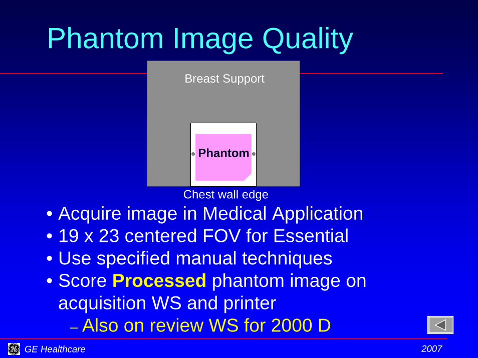
Phantom
Breast Support
Chest wall edge
• Acquire image in Medical Application• 19 x 23 centered FOV for Essential• Use specified manual techniques• Score Processed phantom image on
acquisition WS and printer– Also on review WS for 2000 D
GE Healthcare 2007
Change of CNR Test: 2000 D
• Use image from phantom IQ test.• Analyze largest mass in Raw image
of phantom.• Measurement compared to baseline
established from average of five measurements over five days.

GE Healthcare 2007
Change of CNR Test: 2000 D
Second ROI centeredbetween largest massand group of largestspecks.
1
2
First ROI centered over largest mass
• Difference of means measures contrast.
• Std. Dev. of background measures noise.
∆CNR must not exceed 0.2.

GE Healthcare 2007
MTF Measurement: 2000 D
• Check of detector MTF– Minimal magnification
• Bar pattern on surface of Bucky– Para. or perp. to chest wall edge.– To avoid false results, the pattern must
be clean and free from scratches.• Remove compression paddle.• Set specified parameters. • Acquire image in Medical Application• Analyze Raw image.

GE Healthcare 2007
MTF Measurement: 2000 D
ROI to measure mean of “space” material.
ROI to measure mean of “bar” material.
ROI to measure std. dev. of “2 lp/mm” pattern.
ROI to measure std. dev. of “4 lp/mm” pattern.
••• ••• •••1.
0
1.11
1.23
2.09
3.93
%222MeanMean
.Dev.StdMTFbarspace
×−
=
GE Healthcare 2007
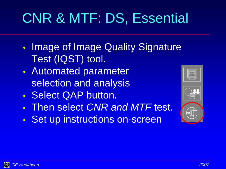
CNR & MTF: DS, Essential
• Image of Image Quality Signature Test (IQST) tool.
• Automated parameter selection and analysis
• Select QAP button.• Then select CNR and MTF test.• Set up instructions on-screen
GE Healthcare 2007
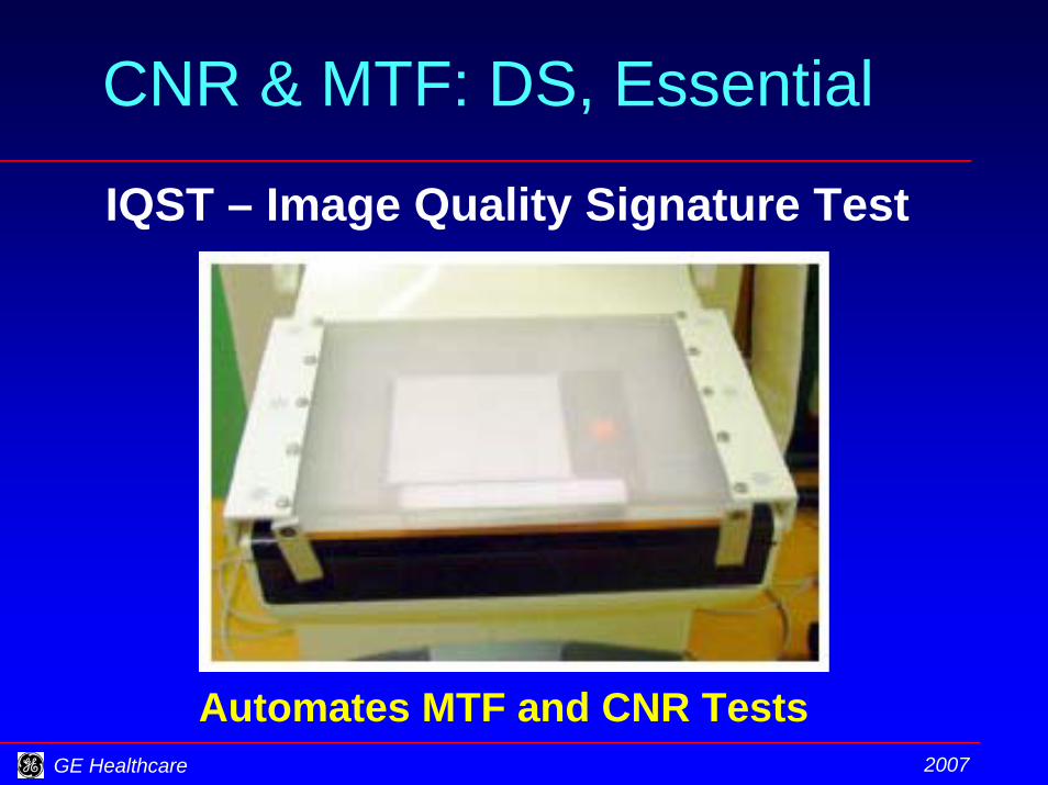
CNR & MTF: DS, Essential
IQST – Image Quality Signature Test
Automates MTF and CNR Tests

GE Healthcare 2007
CNR & MTF: DS, Essential
Resolution Uniformity
Contrast
MTF
Noise Power Spectrum

GE Healthcare 2007
CNR & MTF: DS, Essential
• Measurement compared to baseline established from average of five measurements over five days.– Comparison not valid until after fifth
measurement.• Results, Action Limits, and Pass/Fail
posted at end of test.– If failed, ensure that FineView has not
been changed from previous setting.

GE Healthcare 2007
AOP Mode and SNR Check
Check for • Correct selection of
– kVp, – anode track, – filter, and – mAs and
• Correct level of SNRusing Automatic Optimization of Parameters (AOP) when varyingphantom thickness.
GE Healthcare 2007
AOP Mode and SNR Check
For 2000 D• Acquire images in Medical App.• Select the STD AOP mode.• Acquire images.• Record parameters selected. • Open the Raw images for analysis.• Set the Zoom to “True Size.”• Set ROI, read mean and std. dev.• Calculate SNR.
GE Healthcare 2007
AOP Mode and SNR Check
For DS, Essential• Select QAP button.• Then select AOP and SNR Check.• Set up instructions on-screen.• AOP mode selected automatically.• Acquire images.• Parameters compared to specs.• Results, Action Limits, and Pass/Fail
posted automatically at end of test.

GE Healthcare 2007
AOP Test Plates
Seno 2000 D Seno DS, Essential
20 x 20 cm2 21 cm10 cm

GE Healthcare 2007
AOP Test Plate Change
Improved simulation of breast shape

GE Healthcare 2007
AOP Change & Phantom IQ
• Seno 2000 D– Mo / Mo, 26 kVp, 125 mAs– Simulates AOP CNT mode– “film-like”
• Seno DS and Essential– Rh / Rh, 29 kVp, 56 mAs– Simulates AOP STD mode– “digital”

GE Healthcare 2007
AOP ChangePredicted Track / Filter Combination Use
Mo/Mo, 1%
Rh/Rh, 79%
Mo/Rh, 20%
N.Shramchenko, P.Blin, C.Mathey and R.Klausz. Optimized exposure control in digital mammography.Medical Imaging 2004: Physics of Medical Imaging, Proc. SPIE 5368, 445-456 (2004)
Optimized for consistent CNR rather than detector exposure

GE Healthcare 2007
The QC Tests
Tests that need no introduction

GE Healthcare 2007
QC Tests for the Med. Phys.
• kVp Accuracy and Reproducibility• Beam Quality Assessment (HVL)• Radiation Output• Mammographic Unit Assembly
Evaluation
Tests not unique to FFDM.No procedures provided in the QC plan.

GE Healthcare 2007
The QC Tests
FFDM-specific, FFDM-modified tests
GE Healthcare 2007
Collimation Assessment
Seno 2000 D• Only 24 x 30 film and cassette identified in
equipment list– Will be generalized in next revision
Seno DS and Essential • Identify “auxiliary image receptor”
– 24 x 30 cassette– smaller cassette rotated and/or elevated– general rad. screen-film or CR cassette– multiple, small, distributed detectors
GE Healthcare 2007
Collimation Assessment
• Check both Mo and Rh anode tracksSeno Essential• Acceptance, after a major repair (MEE)
– 24 cm x 30.7 cm– 19 cm x 23 cm, centered– 19 cm x 23 cm, offset right– 19 cm x 23 cm, offset left
• Annual QC survey– 24 cm x 30.7 cm
GE Healthcare 2007
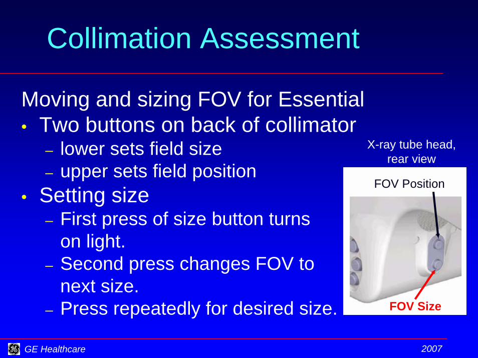
Collimation Assessment
Moving and sizing FOV for Essential• Two buttons on back of collimator
– lower sets field size– upper sets field position
• Setting size– First press of size button turns
on light.– Second press changes FOV to
next size.– Press repeatedly for desired size.
X-ray tube head,rear view
FOV Position
FOV Size

GE Healthcare 2007
Collimation Assessment
Moving and sizing FOV for Essential• Setting position
– First press of position button turns on light.
– Second press moves FOV to next position.
– Press repeatedly for desired position.
X-ray tube head,rear view
FOV Position
FOV Size
GE Healthcare 2007
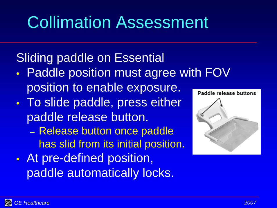
Collimation Assessment
Sliding paddle on Essential• Paddle position must agree with FOV
position to enable exposure.• To slide paddle, press either
paddle release button.– Release button once paddle
has slid from its initial position. • At pre-defined position,
paddle automatically locks.
GE Healthcare 2007
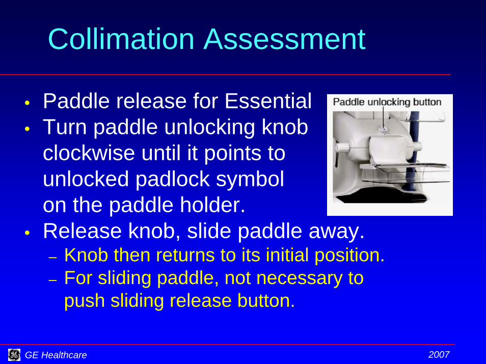
Collimation Assessment
• Paddle release for Essential• Turn paddle unlocking knob
clockwise until it points to unlocked padlock symbol on the paddle holder.
• Release knob, slide paddle away. – Knob then returns to its initial position.– For sliding paddle, not necessary to
push sliding release button.

GE Healthcare 2007
Collimation Assessment
Suggested procedure for Essential• Set gantry at 0 degrees.• Set 19 x 23 FOV size (lower button).• Set FOV position (upper button).• Mark the light field edges.• Install sliding 19 x 23 paddle to
match FOV position.• Make the exposures.

GE Healthcare 2007
“Filmless” Collimation Test
10" x 12" sheet
Use of GAFCHROMIC® XR-QA
3.2 mm Aluminum plate
42 chips per sheet
Light field
4 x 4 cm2 chip

GE Healthcare 2007
“Filmless” Collimation Test
Set up• White side up• Better contrast of light fieldExposure• 30 kVp, 200 mAs, Mo/Mo and Rh/Rh• Self-develops “instantaneously”Attenuator• 3.2 mm aluminum• Useful contrast on film at exposure level used• Avoid detector saturation and “ghost” images

GE Healthcare 2007
“Filmless” Collimation TestGAFCHROMIC® XR-M
3.2 mm Aluminum plate
Light field
XR-M film strip placed white side up
White paperOrange
side(case marked)
Whiteside
International Specialty Productshttp://www.ispcorp.com/products/dosimetry/content/gafchromic/index.html

GE Healthcare 2007
“Filmless” Collimation TestGAFCHROMIC® XR-M
light fieldx-ray field
detector
Light – X-ray deviation = 5 mmX-ray – Detector dev. = 4 mmin film plane.
Then scale to detector plane.

GE Healthcare 2007
Focal Spot Performance
• Film-based • Essentially the same as screen-film
test.• Magnification tested at 1.5X.• Recommend to replace with Sub-
System MTF test

GE Healthcare 2007
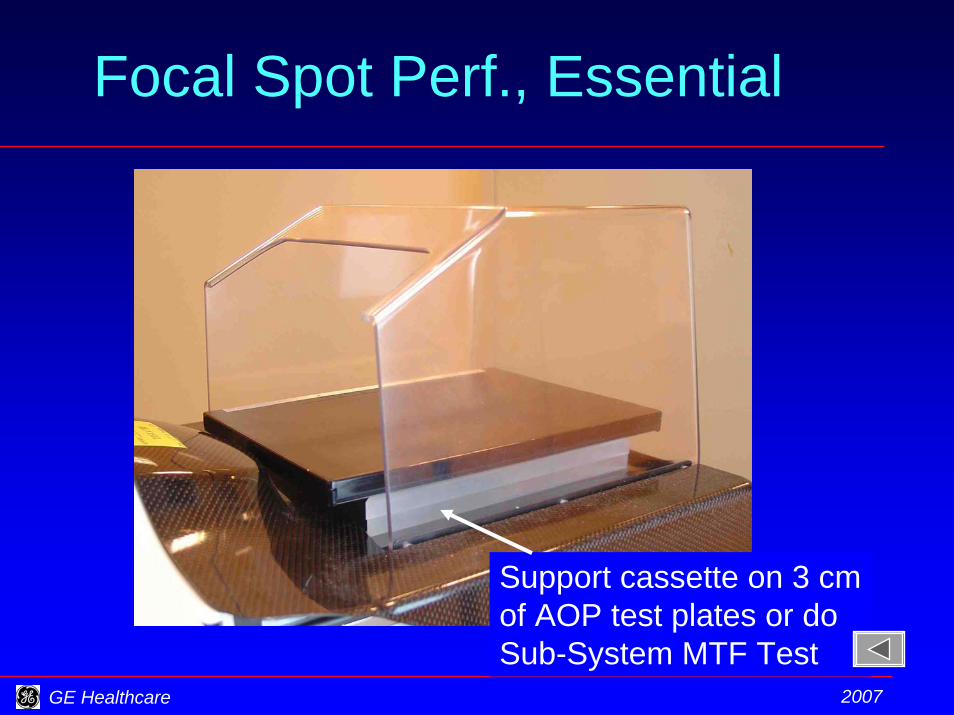
Focal Spot Perf., Essential
For test of small focal spot, cassette will not lie flat on detector cover
GE Healthcare 2007
Focal Spot Perf., Essential
Support cassette on 3 cm of AOP test plates or do Sub-System MTF Test
GE Healthcare 2007
Sub-System MTF
• Bar pattern at 4.5 cm above breast support– Tests focal spot plus detector sub-system.
• Film-less measurement• Option to replace detector MTF test and
(film-based) Eval. of Focal Spot Perf.• Physicist must provide two bar patterns
– “low freq.” with 2.09 and 3.93 lp/mm– “high freq.” with 5 and 8 lp/mm
• Fine View must be disabled (DS & Ess.).
GE Healthcare 2007
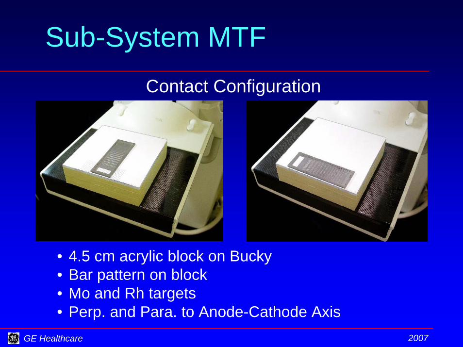
Sub-System MTFContact Configuration
• 4.5 cm acrylic block on Bucky• Bar pattern on block• Mo and Rh targets• Perp. and Para. to Anode-Cathode Axis
GE Healthcare 2007
Sub-System MTF
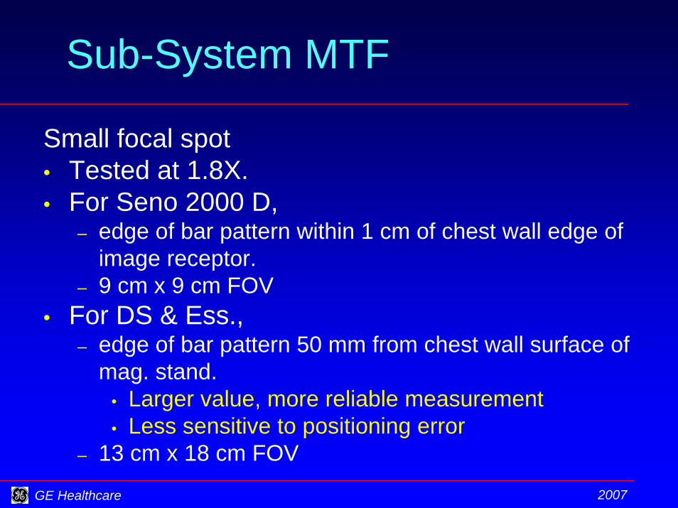
Small focal spot • Tested at 1.8X.• For Seno 2000 D,
– edge of bar pattern within 1 cm of chest wall edge of image receptor.
– 9 cm x 9 cm FOV• For DS & Ess.,
– edge of bar pattern 50 mm from chest wall surface of mag. stand.
• Larger value, more reliable measurement• Less sensitive to positioning error
– 13 cm x 18 cm FOV
GE Healthcare 2007
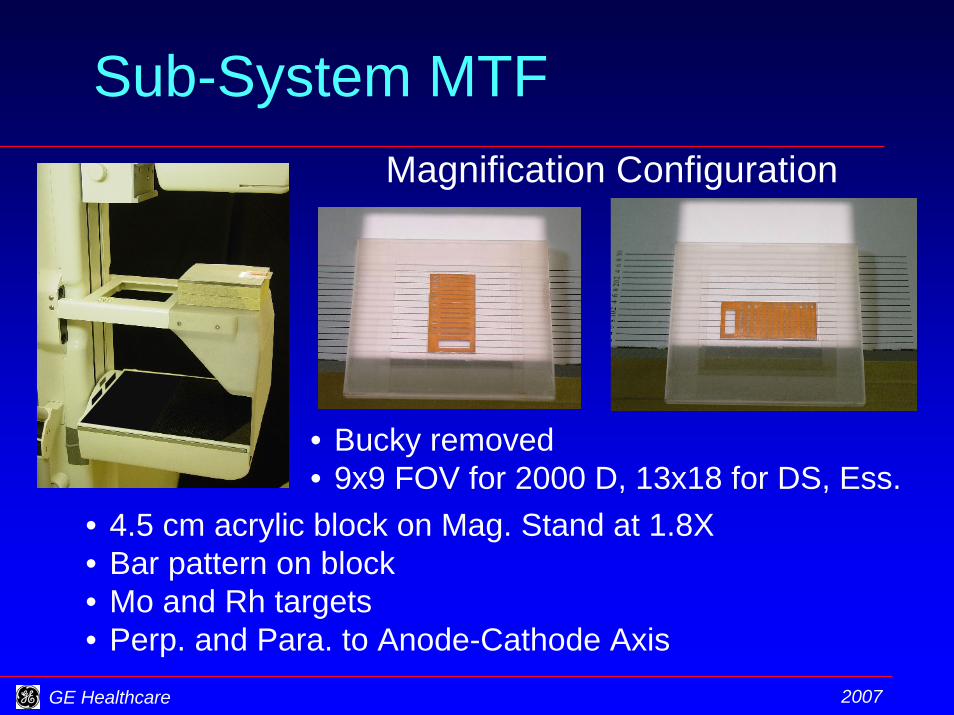
Sub-System MTFMagnification Configuration
• Bucky removed• 9x9 FOV for 2000 D, 13x18 for DS, Ess.
• 4.5 cm acrylic block on Mag. Stand at 1.8X• Bar pattern on block• Mo and Rh targets• Perp. and Para. to Anode-Cathode Axis
GE Healthcare 2007
Sub-System MTF Test
3.934.37
1.0
1.11
1.23
1.37
1.52
1.69
1.88
2.092.322.582.873.193.54
4.86
2.09
3.93
3
4
1
1
2
2
205
810
1112
1314
1516
1718 19
3 4
1
2
51
82
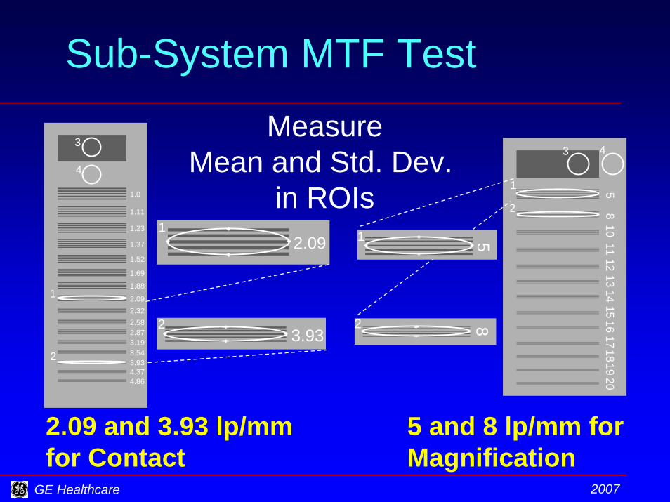
MeasureMean and Std. Dev.
in ROIs
2.09 and 3.93 lp/mm for Contact
5 and 8 lp/mm for Magnification
GE Healthcare 2007
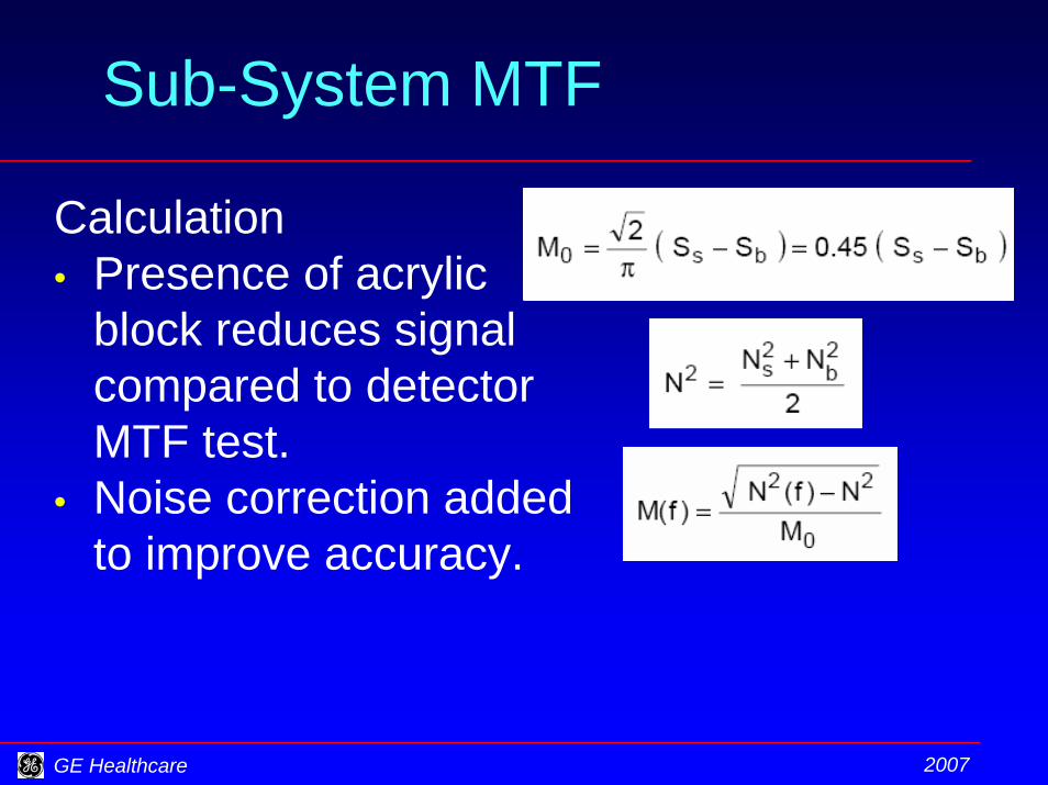
Sub-System MTF
Calculation• Presence of acrylic
block reduces signalcompared to detectorMTF test.
• Noise correction addedto improve accuracy.
GE Healthcare 2007
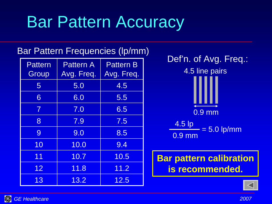
Bar Pattern Accuracy
PatternGroup
Pattern AAvg. Freq.
Pattern BAvg. Freq.
5 5.0 4.56 6.0 5.57 7.0 6.58 7.9 7.59 9.0 8.5
10 10.0 9.411 10.7 10.512 11.8 11.213 13.2 12.5
Bar Pattern Frequencies (lp/mm)
4.5 lp0.9 mm
= 5.0 lp/mm
0.9 mm
4.5 line pairsDef’n. of Avg. Freq.:
Bar pattern calibration is recommended.
GE Healthcare 2007
Exposure, Dose, Repro.
Dose in Automatic Optimization ofParameters (AOP) mode measured by• Acquiring image of accreditation
phantom and recording parameters,• Replacing phantom by ion chamber, • Setting AOP-selected parameters in
Manual mode,• Measuring exposure for selected
parameters.
GE Healthcare 2007
Exposure, Dose, Repro.
AOP parameter selection based on• Most attenuating “breast” tissue in
AOP sense window.– May reject highly attenuating object.
• Breast composition– Based on attenuation and compression
paddle heightFor accurate dose measurement• No high attenuators in sense window• No objects on phantom top
GE Healthcare 2007
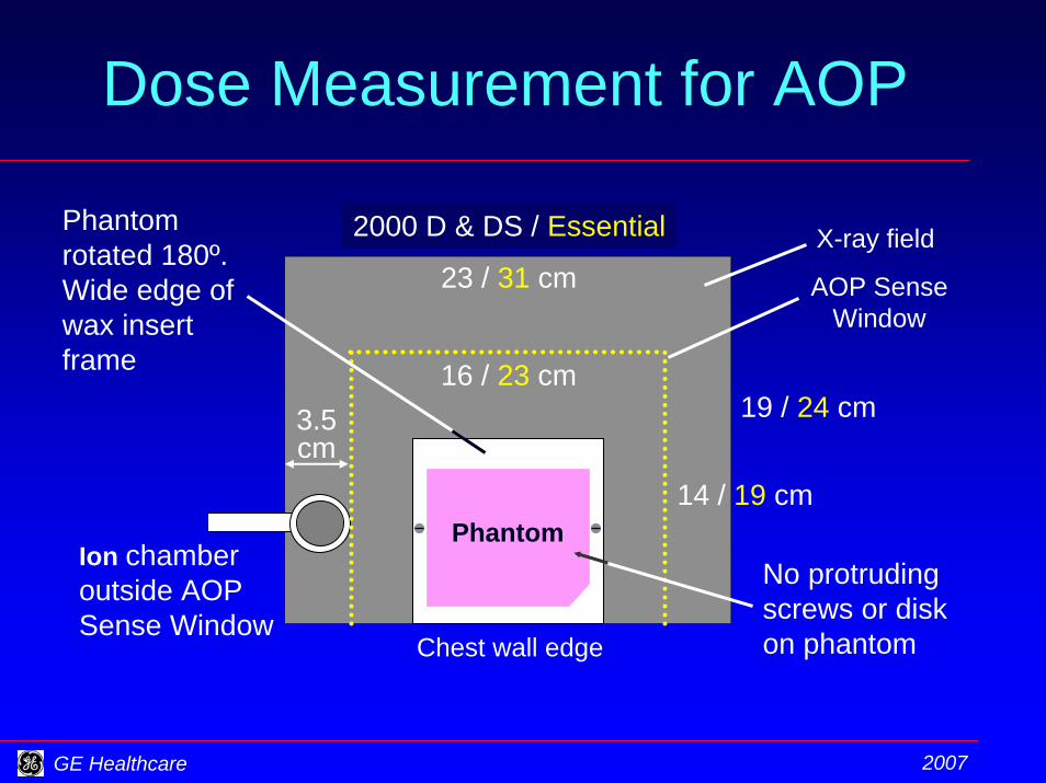
Dose Measurement for AOP
X-ray field
Chest wall edge
Ion chamber outside AOP Sense Window
16 / 23 cm
23 / 31 cm
3.5 cm
14 / 19 cm
19 / 24 cm
AOP SenseWindow
Phantom
Phantom rotated 180º.Wide edge of wax insert frame
2000 D & DS / Essential
No protruding screws or disk on phantom
GE Healthcare 2007
Exposure, Dose Summary
• AOP parameter selection is more consistent with phantom rotated 180°.
• Acrylic disk on phantom increases dose.• Disk and raised thumbscrews cause
thickness estimate error.• Consistent compression force of 5 daN
improves AOP consistency.• ACR method – uniform phantom – is only
for accreditation application, not QC.

GE Healthcare 2007
Artifact Eval., Flat Field Unif.
• Image of uniform acrylic plate• Mo/Mo, Mo/Rh, Rh/Rh at lowest clinical
kVp• Large focal spot with grid in• Small focal spot without grid• Review Raw image• Set window width to 400 - 450• Visual evaluation of uniformity• No artifact or non-uniformity that is
expected to mimic or obscure clinical information
GE Healthcare 2007
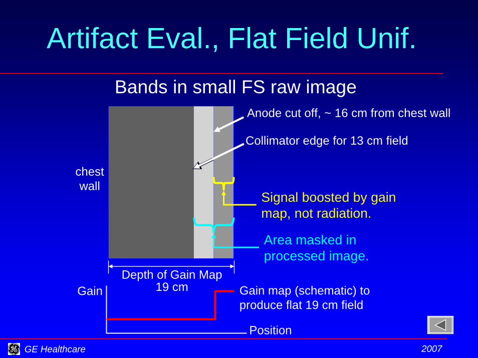
Artifact Eval., Flat Field Unif.Bands in small FS raw image
Anode cut off, ~ 16 cm from chest wall
Depth of Gain Map19 cm
Collimator edge for 13 cm field
chestwall
Signal boosted by gain map, not radiation.
Area masked in processed image.
Gain map (schematic) to produce flat 19 cm field
Gain
Position

GE Healthcare 2007
Viewing Conditions Check and Setting• Set intended illuminance for interpretation of
mammograms.• Darken displays.• Measure illuminance at display screens.• For the RWS, recommend reducing ambient
illuminance upper limit from 50 to 20 lux.• For Seno Advantage, upper limit is 20 lux.• Provide “map” enabling RT to reproduce
illuminance conditions of your measurement.

GE Healthcare 2007
Monitor Calibration
• Not a calibration, but a check.• Field Engineer sets black / white levels.
– Uses external, calibrated photometer.• FE performs perceptual linearization.
– Uses internal photometer.• FE records 5 baseline
luminance levels.– Uses internal photometer.
• During QC, physicistcompares lum. levelsto baseline.– Uses internal photometer.
0 50 100 150 200 250Digital Driving Level
Log
Lum
inan
ce
L255L180L120
L60L10

GE Healthcare 2007
Monitor Calibration
• For “RWS,” background set to DDL = 180.
• For Seno Advantage, background set to DDL that gives luminance ~ 20% of luminance for DDL = 255.
• Encourage QC RT to ensure that Field Engineer leaves baseline luminance values after re-calibration.

GE Healthcare 2007
Image Quality–SMPTE Pattern
• Be sure to use SMPTE pattern from graphics display driver not Browser or elsewhere.– Center of pattern must have bar pattern
not black and white squares.
• Examine image for the listed features.
GE Healthcare 2007
Display Screen Uniformity
• Screen set to DDL = 255.• Examine screen for artifacts.• During system acceptance• When necessary to isolate system
artifacts.– Not an annual test
• No artifact or non-uniformity that is expected to mimic or obscure clinical information

GE Healthcare 2007
Thank you

GE Healthcare 2007
Appendix

GE Healthcare 2007
DS & Essential: Auto. RRA
Automated Repeat / Reject Analysis (RRA)• User classifies each image
• Accept (default)• Repeat (extra dose to patient)• Reject (no intention to keep, e.g., QC test)
• User assigns cause to each Repeat and Reject• System maintains data base• Repeat, Reject rates posted at user’s request• Export database for off-line analysis
Replace paper-based record keeping, hand calculations.
GE Healthcare 2007
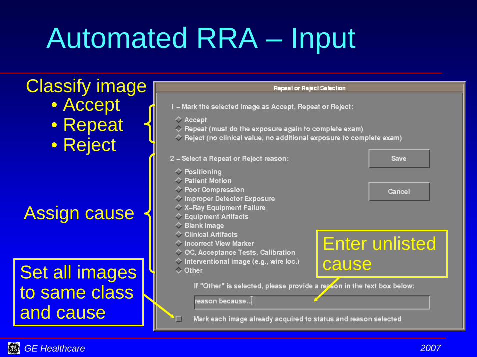
Automated RRA – InputClassify image
• Accept• Repeat• Reject
Assign causeEnter unlisted causeSet all images
to same class and cause
GE Healthcare 2007
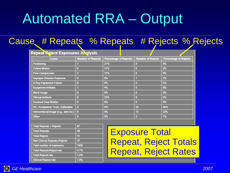
Automated RRA – OutputCause # Repeats % Rejects# Rejects% Repeats
Exposure TotalRepeat, Reject TotalsRepeat, Reject Rates


