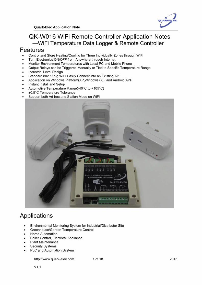
Quark-Elec Application Note http://www.quark-elec.com 1 of 18 2015 V1.1 QK-W016 WiFi Remote Controller Application Notes —WiFi Temperature Data Logger & Remote Controller Features • Control and Store Heating/Cooling for Three Individually Zones through WiFi • Turn Electronics ON/OFF from Anywhere through Internet • Monitor Environment Temperatures with Local PC and Mobile Phone • Output Relays can be Triggered Manually or Tied to Specific Temperature Range • Industrial Level Design • Standard 802.11b/g WiFi Easily Connect into an Existing AP • Application on Windows Platform(XP,Windows7,8), and Android APP • Instant Install and Setup • Automotive Temperature Range(-40°C to +105°C) • ±0.5°C Temperature Tolerance • Support both Ad-hoc and Station Mode on WiFi Applications • Environmental Monitoring System for Industrial/Distributor Site • Greenhouse/Garden Temperature Control • Home Automation • Boiler Control, Electrical Appliance • Plant Maintenance • Security Systems • PLC and Automation System
Transcript
Quark-Elec Application Note
http://www.quark-elec.com 1 of 18 2015
V1.1
QK-W016 WiFi Remote Controller Application Notes —WiFi Temperature Data Logger & Remote Controller
Features • Control and Store Heating/Cooling for Three Individually Zones through WiFi • Turn Electronics ON/OFF from Anywhere through Internet • Monitor Environment Temperatures with Local PC and Mobile Phone • Output Relays can be Triggered Manually or Tied to Specific Temperature Range • Industrial Level Design • Standard 802.11b/g WiFi Easily Connect into an Existing AP • Application on Windows Platform(XP,Windows7,8), and Android APP • Instant Install and Setup • Automotive Temperature Range(-40°C to +105°C) • ±0.5°C Temperature Tolerance • Support both Ad-hoc and Station Mode on WiFi
Applications • Environmental Monitoring System for Industrial/Distributor Site • Greenhouse/Garden Temperature Control • Home Automation • Boiler Control, Electrical Appliance • Plant Maintenance • Security Systems • PLC and Automation System
Quark-Elec Application Note
http://www.quark-elec.com 2 of 18 2015
V1.1
Document History
Issue Date Changes / Comments
1.0 12-06-2015 Initial release
1.1 16-12-2015 Android APP version release
Order Information
Part No Description
QK-W016 WiFi Remote controller (three relays output, Three temperature sensors input)
1.1 POWER UP .......................................................................................................................... 4 1.2 ACCESS QK-W016.............................................................................................................. 4
2.1 WINDOWS APPLICATION....................................................................................................... 9 2.2 ANDROID APP.................................................................................................................... 10
3 TEMPERATURE MONITOR & CONTROL......................................................................... 10
3.1 TEMPERATURE SETTING IN PROGRAM ................................................................................. 11 3.2 TEMPERATURE DATA LOGGER............................................................................................. 12
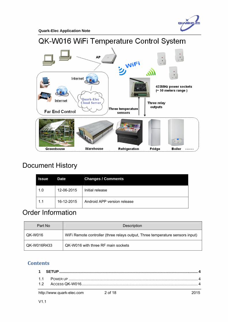
QK-W016 series WiFi temperature monitoring remote controller is a versatile device which can be attached to domestic freezer, water tanks, refrigerator, industrial chiller, boiler, steamer, warehouse, green house, industrial equipments and other temperature-controlling systems. Operators can control remote equipments, heater, lights, machines, or power sockets from anywhere in the world through internet.
Three wired thermistor sensors measure temperature at different zone. QK-W016 energizes the corresponding relays according to the measured temperatures. QK-W016 can be fitted in any situation where an object is required to be heated, cooled or both to remain at the target temperature range(set by PC application or Android APP).
An integrated WiFi module allows operator could check the temperature log data, and manually switch the relays across the existing WiFi network.
QK-W016 also has an optional RF 433Mhz module allows operator to switch RF main sockets within 50 meters range of it.
Quark-Elec Application Note
http://www.quark-elec.com 4 of 18 2015
V1.1
Figure 1 System diagram (Station mode)
1 SETUP
1.1 Power up QK-W016 remote controller should be powered by 12VDC voltage. Connect a 12VDC 1.0Amp power supply to the power socket, switch on the power supply, the blue LED should light up and then flashing slowly. After about 10 seconds, the red LED will light up indication system finishes initialization.
1.2 Access QK-W016 Quark-elec have released Windows (XP, 7, 8 and later version) application and Android APP for QK-W016 by now. iOS will be available soon. Operator can use the following link to download the latest version of the application or APP:
http://www.quark-elec.com/download/apps
For some computers which fitted old Ethernet network card(RJ45 cable connected card), it is recommend to disconnect the RJ45 cable during processing the following steps.
--- After QK-W016 finish initialization, operator should be able to scan and find a WiFi network (SSID) called ‘WiFi168’ in the computer or mobile phone.
Quark-Elec Application Note
http://www.quark-elec.com 5 of 18 2015
V1.1
--- Connect the computer or mobile phone to ‘WiFi168’ with ‘88888888’ as the default password. Blue LED will keep lighting up once the connection is setup. In the case that ‘WiFi168’ cannot be found on the computer or the mobile phone, please go to ‘Reset QK-W016’ section following the steps to reset the module.
1.3 Reset QK-W016 Operator can always reset QK-W016 if the setting is incorrect or would like to change the working mode. Following below steps to reset QK-W016 to the factory settings:
1, Power off QK-W016.
2, Press and hold the ‘Reset’ button, then power up QK-W016. Blue LED will light up for few seconds, then the red LED turns on. Keep the red LED turns on for at least 3 seconds, release ‘Reset ’button.
3, Wait for 60 seconds, the red LED turns off and then turns on again. Once the red LED turns on, the initialization process complete. During the initialization period, the blue LED is blinking every second.
4, Operator can now scan WiFi network and find a ‘WiFi168’ network to connect.
1.4 Ad-hoc mode The IEEE 802.11b/g has two basic modes of operation: Ad-hoc mode and infrastructure mode(also called station mode). In ad hoc mode, mobile terminals transmit directly peer-to-peer. While In infrastructure mode, mobile terminals communicate through an access point(AP) that serves as a bridge to other networks (such as Internet or LAN). QK-W016 WiFi controller can support in both Ad-hoc and station mode.
Setting QK-W016 works in Ad-hoc mode is quite straightforward. Once the computer or the mobile phone connect to ‘WiFi168’ network, power off the QK-W016 and then re-power it up (this is important) until both red and blue LEDs light up. QK-W016 is working in Ad-hoc mode now.
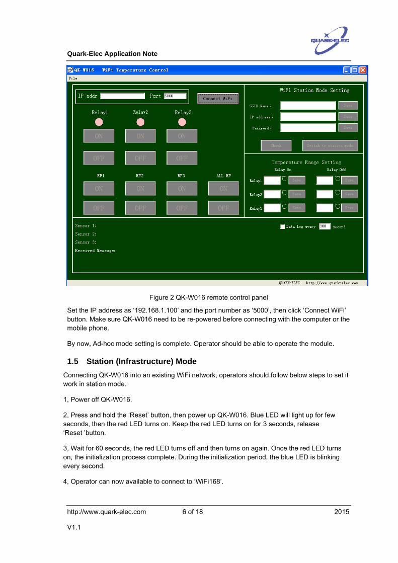
Operator should also set the IP address and port number on the application page or APP control panel before using the module. Take the PC application as an example, the main application page is similar as below.
Quark-Elec Application Note
http://www.quark-elec.com 6 of 18 2015
V1.1
Figure 2 QK-W016 remote control panel
Set the IP address as ‘192.168.1.100’ and the port number as ‘5000’, then click ‘Connect WiFi’ button. Make sure QK-W016 need to be re-powered before connecting with the computer or the mobile phone.
By now, Ad-hoc mode setting is complete. Operator should be able to operate the module.
1.5 Station (Infrastructure) Mode Connecting QK-W016 into an existing WiFi network, operators should follow below steps to set it work in station mode.
1, Power off QK-W016.
2, Press and hold the ‘Reset’ button, then power up QK-W016. Blue LED will light up for few seconds, then the red LED turns on. Keep the red LED turns on for 3 seconds, release ‘Reset ’button.
3, Wait for 60 seconds, the red LED turns off and then turns on again. Once the red LED turns on, the initialization process complete. During the initialization period, the blue LED is blinking every second.
4, Operator can now available to connect to ‘WiFi168’.
Quark-Elec Application Note
http://www.quark-elec.com 7 of 18 2015
V1.1
5, Set the IP address as ‘192.168.1.100’ and the port number as ‘5000’, then click ‘Connect WiFi’ button in the application software. Make sure DON’T re-power the module after connection in this step, otherwise the module will work in Ad-hoc mode.
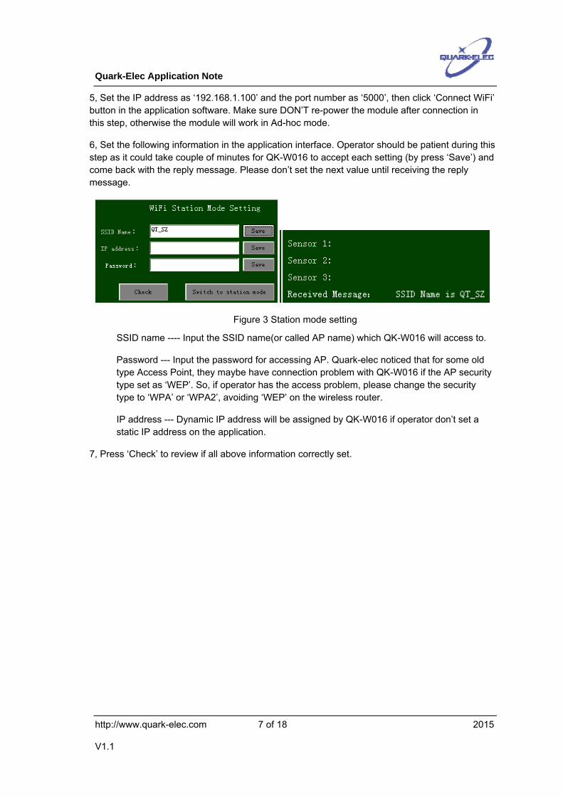
6, Set the following information in the application interface. Operator should be patient during this step as it could take couple of minutes for QK-W016 to accept each setting (by press ‘Save’) and come back with the reply message. Please don’t set the next value until receiving the reply message.
Figure 3 Station mode setting
SSID name ---- Input the SSID name(or called AP name) which QK-W016 will access to.
Password --- Input the password for accessing AP. Quark-elec noticed that for some old type Access Point, they maybe have connection problem with QK-W016 if the AP security type set as ‘WEP’. So, if operator has the access problem, please change the security type to ‘WPA’ or ‘WPA2’, avoiding ‘WEP’ on the wireless router.
IP address --- Dynamic IP address will be assigned by QK-W016 if operator don’t set a static IP address on the application.
7, Press ‘Check’ to review if all above information correctly set.
Quark-Elec Application Note
http://www.quark-elec.com 8 of 18 2015
V1.1
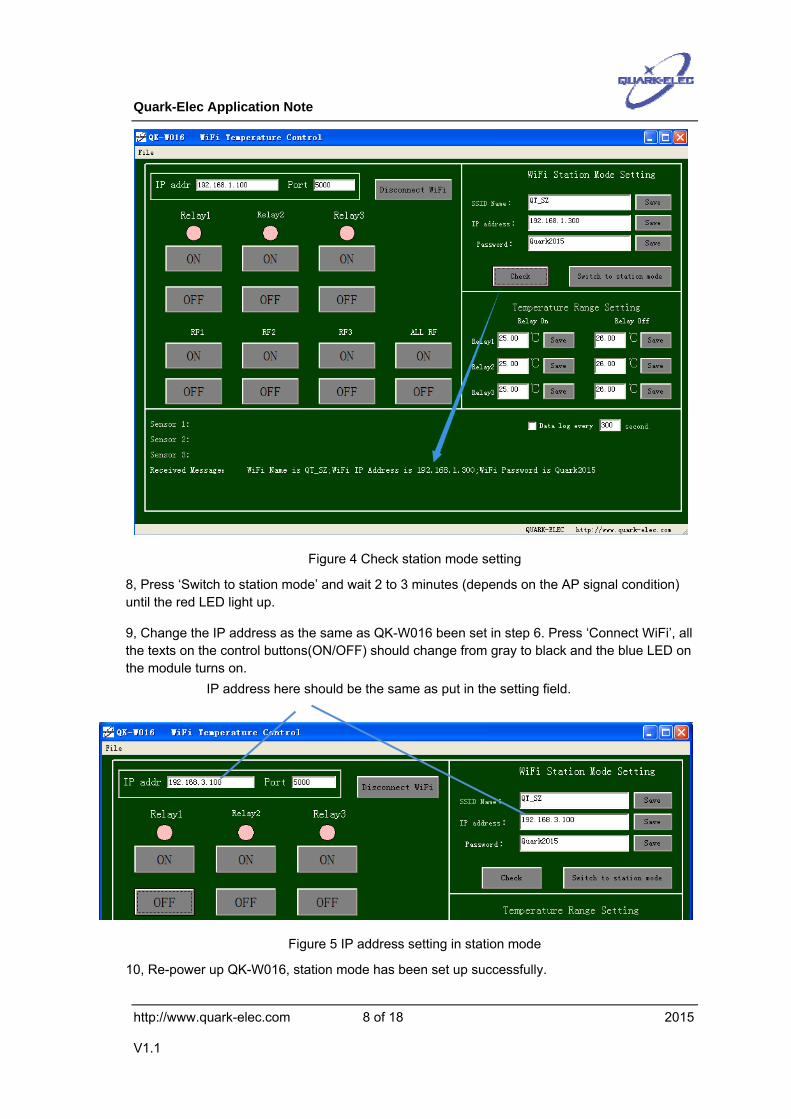
Figure 4 Check station mode setting
8, Press ‘Switch to station mode’ and wait 2 to 3 minutes (depends on the AP signal condition) until the red LED light up.
9, Change the IP address as the same as QK-W016 been set in step 6. Press ‘Connect WiFi’, all the texts on the control buttons(ON/OFF) should change from gray to black and the blue LED on the module turns on.
Figure 5 IP address setting in station mode
10, Re-power up QK-W016, station mode has been set up successfully.
IP address here should be the same as put in the setting field.
Quark-Elec Application Note
http://www.quark-elec.com 9 of 18 2015
V1.1
2 APPLICATION INTERFACE
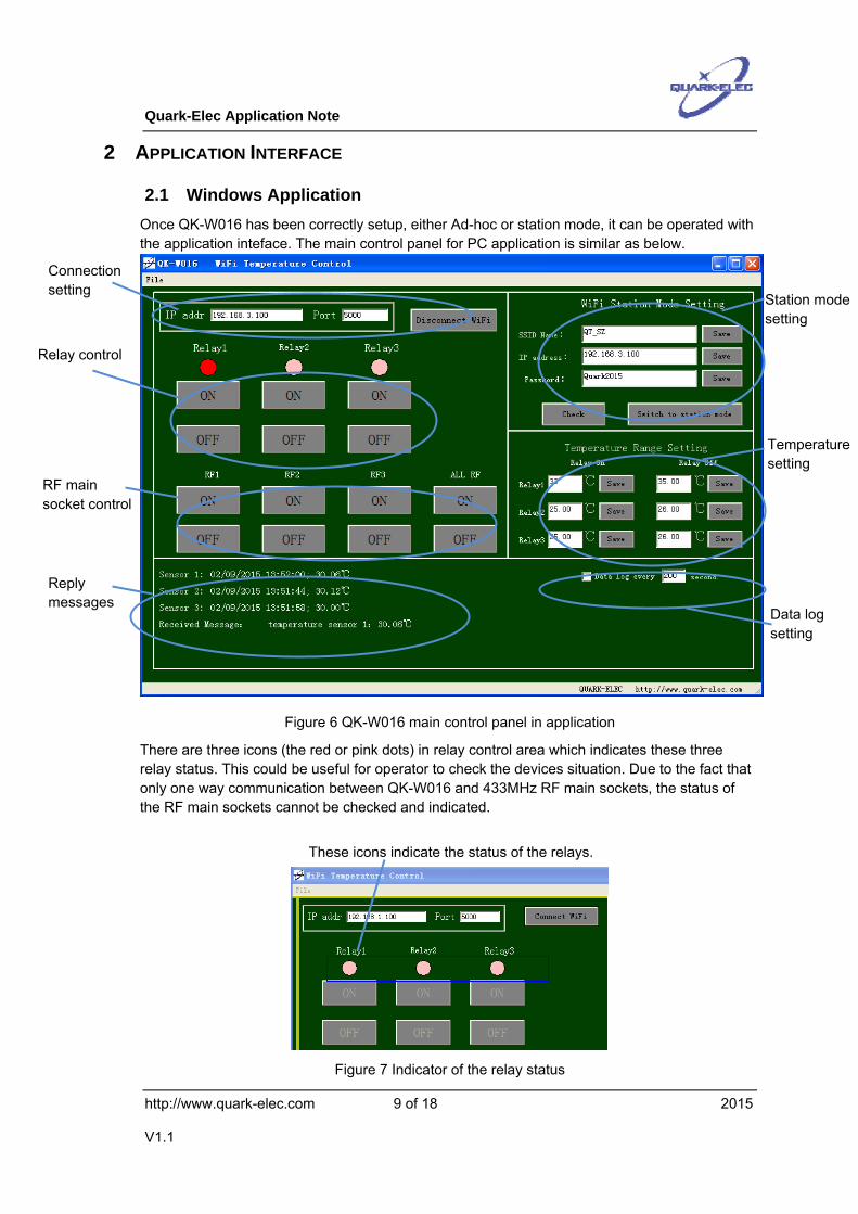
2.1 Windows Application Once QK-W016 has been correctly setup, either Ad-hoc or station mode, it can be operated with the application inteface. The main control panel for PC application is similar as below.
Figure 6 QK-W016 main control panel in application
There are three icons (the red or pink dots) in relay control area which indicates these three relay status. This could be useful for operator to check the devices situation. Due to the fact that only one way communication between QK-W016 and 433MHz RF main sockets, the status of the RF main sockets cannot be checked and indicated.
Figure 7 Indicator of the relay status
These icons indicate the status of the relays.
Connection setting
Relay control
Station mode setting
Temperature setting
Reply messages
RF main socket control
Data log setting
Quark-Elec Application Note
http://www.quark-elec.com 10 of 18 2015
V1.1
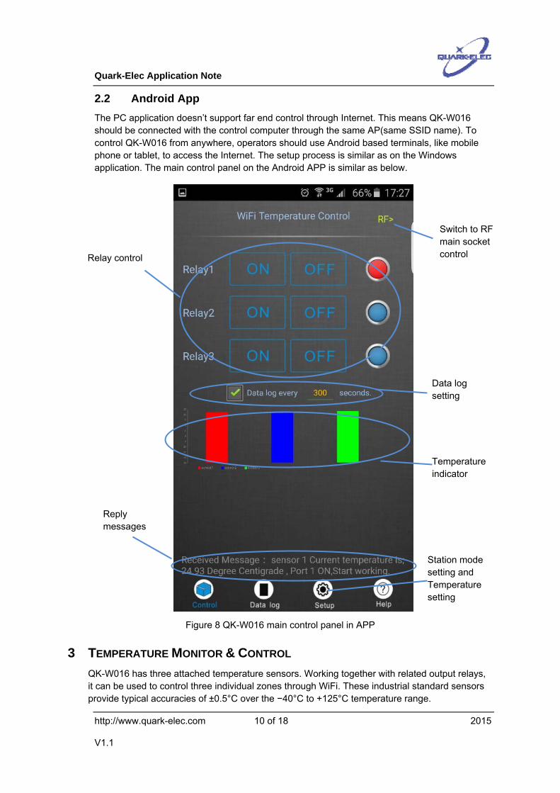
2.2 Android App The PC application doesn’t support far end control through Internet. This means QK-W016 should be connected with the control computer through the same AP(same SSID name). To control QK-W016 from anywhere, operators should use Android based terminals, like mobile phone or tablet, to access the Internet. The setup process is similar as on the Windows application. The main control panel on the Android APP is similar as below.
Figure 8 QK-W016 main control panel in APP
3 TEMPERATURE MONITOR & CONTROL QK-W016 has three attached temperature sensors. Working together with related output relays, it can be used to control three individual zones through WiFi. These industrial standard sensors provide typical accuracies of ±0.5°C over the −40°C to +125°C temperature range.
Relay control
Data log setting
Reply messages
Switch to RF main socket control
Temperature indicator
Station mode setting and Temperature setting
Quark-Elec Application Note
http://www.quark-elec.com 11 of 18 2015
V1.1
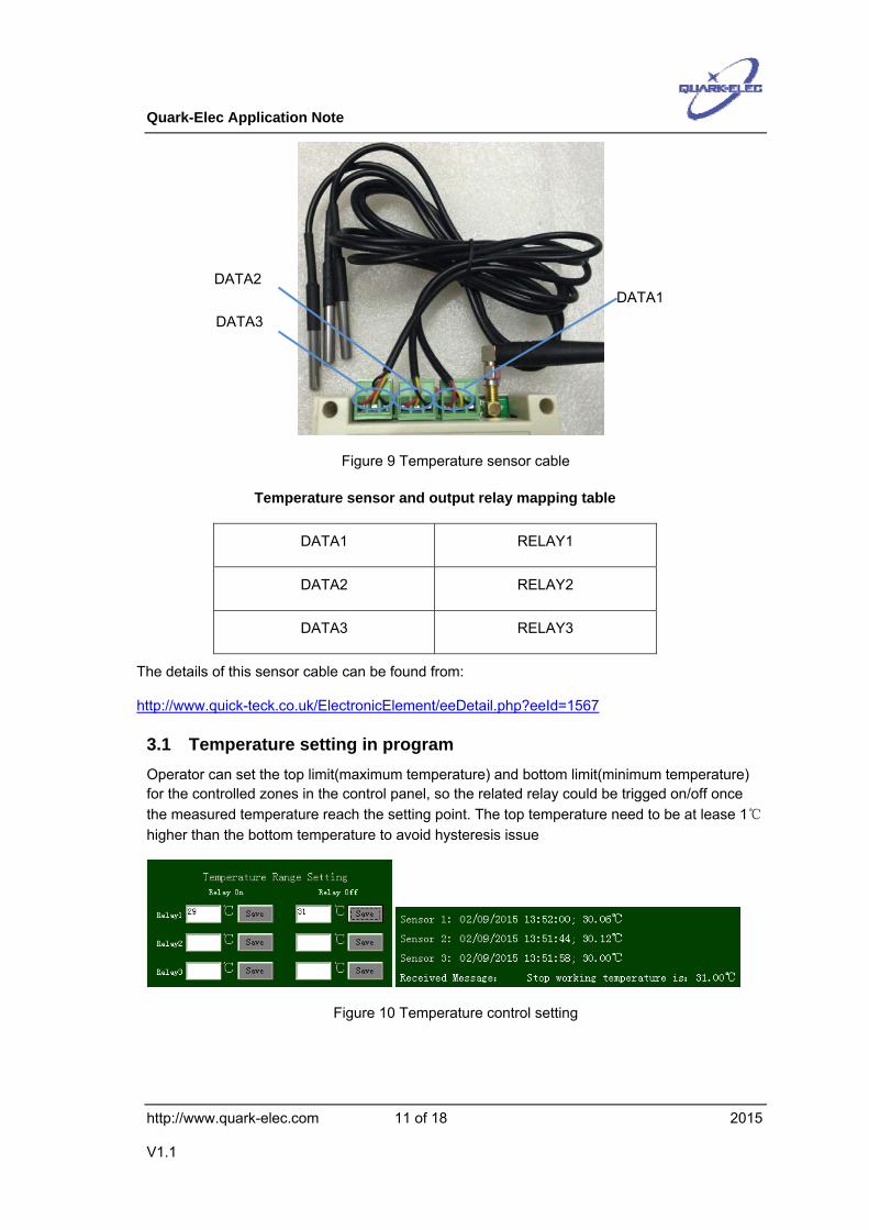
Figure 9 Temperature sensor cable
Temperature sensor and output relay mapping table
DATA1 RELAY1
DATA2 RELAY2
DATA3 RELAY3
The details of this sensor cable can be found from:
3.1 Temperature setting in program Operator can set the top limit(maximum temperature) and bottom limit(minimum temperature) for the controlled zones in the control panel, so the related relay could be trigged on/off once the measured temperature reach the setting point. The top temperature need to be at lease 1℃ higher than the bottom temperature to avoid hysteresis issue
Figure 10 Temperature control setting
DATA1 DATA2
DATA3
Quark-Elec Application Note
http://www.quark-elec.com 12 of 18 2015
V1.1
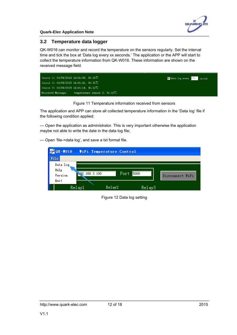
3.2 Temperature data logger QK-W016 can monitor and record the temperature on the sensors regularly. Set the interval time and tick the box at ‘Data log every xx seconds.’ The application or the APP will start to collect the temperature information from QK-W016. These information are shown on the received message field.
Figure 11 Temperature information received from sensors
The application and APP can store all collected temperature information in the ‘Data log’ file if the following condition applied:
--- Open the application as administrator. This is very important otherwise the application maybe not able to write the date in the data log file;
--- Open ‘file->data log’, and save a txt format file.
Figure 12 Data log setting
Quark-Elec Application Note
http://www.quark-elec.com 13 of 18 2015
V1.1
Figure 13 Temperature data logger.
4 SWITCH RELAYS MANUALLY Operator can always manually switch the output relays if needed. QK-W016 doesn’t allow to disable the trigger input from temperature sensor, but operator can set the top and bottom limit temperature to be a unreachable value in this case.
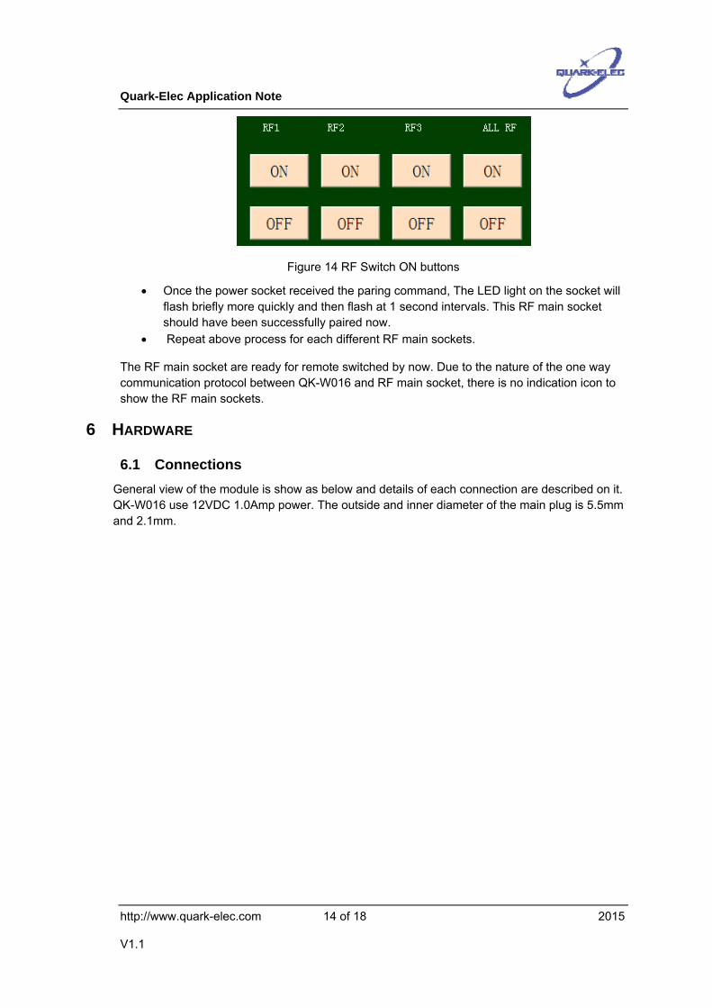
5 PARING WITH RF POWER SOCKETS(OPTIONAL FUNCTION) QK-W016 has a build-in 433Mhz RF transmitter module (as an optional setting, customer should contact Quark-elec for apply this). It can pair with up to three RF power sockets. So the operators are able to turn ON/OFF the electrical devices by switching the power sockets.
The power sockets have been pre-paired and ready for using if they come with QK-W016. However operator can always re-pair or release the pairing by following steps:
• Insert the RF power socket into a powered mains wall socket. • The LED light on the socket should flash at 1 second intervals indicating it’s ready to
pair with the QK-W016. If the lights doesn’t flash, press and hold the ON/OFF button for 5 seconds to clear the memory indicated by the quickly flashing LED.
• Open WiFi Remote control panel in program, press the corresponding RF switch ‘ON’ button. The paring command will be sending out through RF signals.
Quark-Elec Application Note
http://www.quark-elec.com 14 of 18 2015
V1.1
Figure 14 RF Switch ON buttons
• Once the power socket received the paring command, The LED light on the socket will flash briefly more quickly and then flash at 1 second intervals. This RF main socket should have been successfully paired now.
• Repeat above process for each different RF main sockets.
The RF main socket are ready for remote switched by now. Due to the nature of the one way communication protocol between QK-W016 and RF main socket, there is no indication icon to show the RF main sockets.
6 HARDWARE
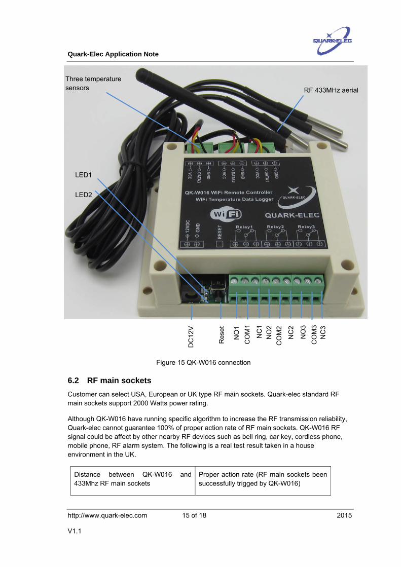
6.1 Connections General view of the module is show as below and details of each connection are described on it. QK-W016 use 12VDC 1.0Amp power. The outside and inner diameter of the main plug is 5.5mm and 2.1mm.
Quark-Elec Application Note
http://www.quark-elec.com 15 of 18 2015
V1.1
Figure 15 QK-W016 connection
6.2 RF main sockets Customer can select USA, European or UK type RF main sockets. Quark-elec standard RF main sockets support 2000 Watts power rating.
Although QK-W016 have running specific algorithm to increase the RF transmission reliability, Quark-elec cannot guarantee 100% of proper action rate of RF main sockets. QK-W016 RF signal could be affect by other nearby RF devices such as bell ring, car key, cordless phone, mobile phone, RF alarm system. The following is a real test result taken in a house environment in the UK.
Distance between QK-W016 and 433Mhz RF main sockets
Proper action rate (RF main sockets been successfully trigged by QK-W016)
RF 433MHz aerial
NC
1
NO
1 C
OM
1
NC
2
NO
2 C
OM
2
NC
3
NO
3 C
OM
3
DC
12V
Res
et
LED2
LED1
Three temperature sensors
Quark-Elec Application Note
http://www.quark-elec.com 16 of 18 2015
V1.1
2 meters 100.0%
5 meters 100.0%
8 meters 99.2%
10 meters 98.1%
15 meters 95.4%
20 meters 93.7%
6.3 Enclosure IP56 Insulation Class 2 plastic enclosure, 115mm*90*40 external dimension is used for QK-W016.


![Hkw] ?kk] Qk]](https://static.documents.pub/doc/80x56/5a8368347f8b9a38478ebcef/hkw-kk-qk-k-s-ks-hkk-hkh-hkw-kk-qk-k-gem-000611-mrigashira-3.jpg)


