27
Commissioning PV Arrays Quickly and Safely Michael Middlemast Business Development Manager for Renewables
| Date post: | 15-Apr-2017 |
| Category: |
Documents |
| Upload: | michael-middlemast |
| View: | 218 times |
| Download: | 2 times |

Commissioning PV Arrays Quickly and Safely
Michael Middlemast
Business Development Manager for Renewables
Disclaimer
This presentation cannot be considered as a replacement for any of the standards referenced within. All reasonable care has been taken to ensure the accuracy of the information. Reference figures and data have been taken from standards, guidance notes and recognised best practice, current at the time the presentation was created, to establish the recommended testing requirements. However, Seaward Group, their agents and distributors, accept no responsibility for any error or omissions within this presentation, or for any misinterpretations by the user. For clarification on any part of this presentation, please contact Seaward Group before operating any test instrument. No part of this presentation shall be deemed to form, or be part of, any contract for training or equipment unless specifically referred to as an inclusion within such contract. Persons performing any electrical tests described in this presentation must be fully competent to do so. Seaward Group does not accept any liability arising from accidents or fatalities resulting directly or indirectly from the tests described in this presentation.

Introduction
“IEC 62446:2016 Grid connected photovoltaic systems – Minimum requirements for system documentation, commissioning tests and inspection” Introduction: “Grid connected PV systems are expected to have a lifetime of decades, with maintenance or modifications likely at some point over this period. Building or electrical works in the vicinity of the PV array are very likely, for example roof works adjacent to the array or modifications (structural or electrical) to a home that has a PV system. The ownership of a system may also change over time, particularly for systems mounted on buildings. Only by the provision of adequate documentation at the outset can the long term performance and safety of the PV system and works, on or adjacent to the PV system, be ensured.”
The International Electrotechnical Commission (IEC) is a globally respected and acknowledged organisation that provides us with a solid frame work for safe working practices.

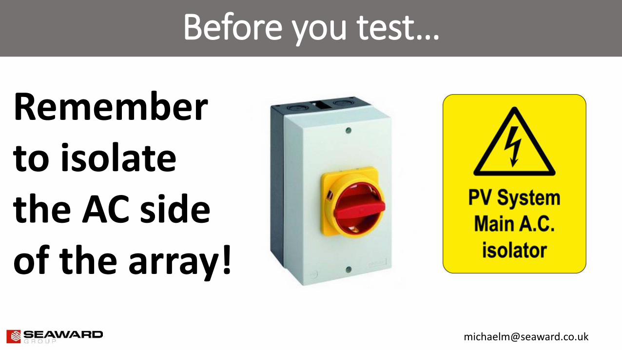
Safety First!
Rubber insulated gloves are your first line of defence against electric shock. You should cover these with leather gloves and make sure to inspect them prior to every use. PPE such as impact helmets and eye protectors are also advised.
PV systems can operate with voltages up to 1000V (soon to be 1500V!) so arc flash requirements are a growing concern. Unfortunately, not all PV systems are clearly labelled, so please take care and be aware of what you testing.
Ensure you perform on-site evaluations prior to carrying out any maintenance and testing works. You may need a higher category of PPE, especially when you’re working in open inverters or verifying voltages in switch gear.
Pre-test Inspection
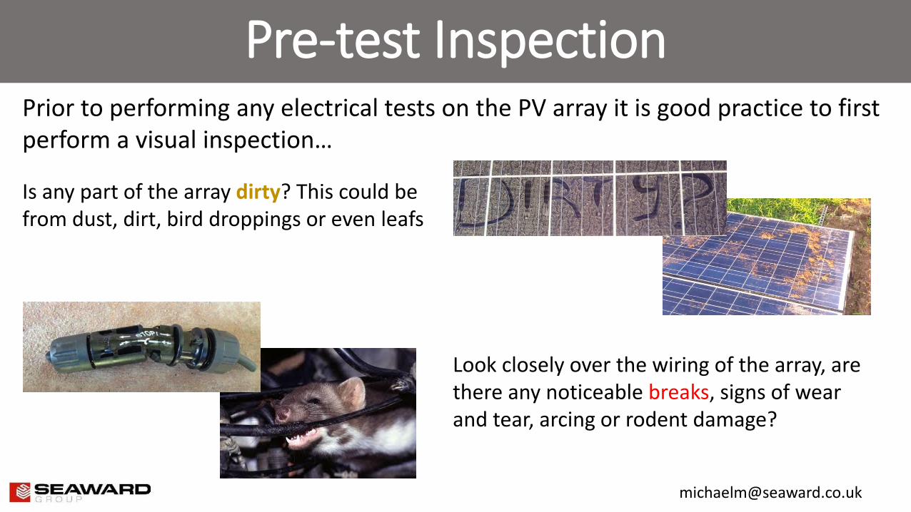
Prior to performing any electrical tests on the PV array it is good practice to first perform a visual inspection…
Look closely over the wiring of the array, are there any noticeable breaks, signs of wear and tear, arcing or rodent damage?
Is any part of the array dirty? This could be from dust, dirt, bird droppings or even leafs
Pre-test Inspection
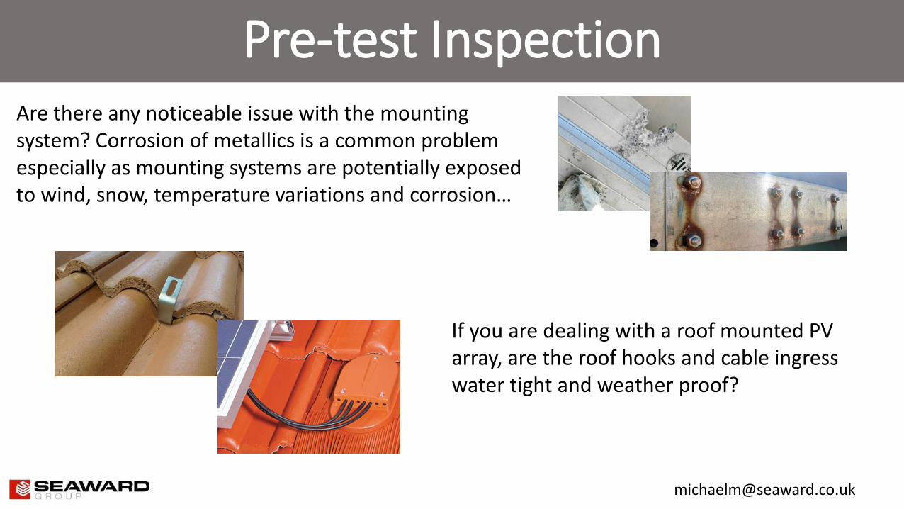
If you are dealing with a roof mounted PV array, are the roof hooks and cable ingress water tight and weather proof?
Are there any noticeable issue with the mounting system? Corrosion of metallics is a common problem especially as mounting systems are potentially exposed to wind, snow, temperature variations and corrosion…
Pre-test Calculations
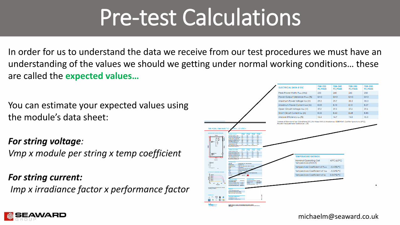
You can estimate your expected values using the module’s data sheet: For string voltage: Vmp x module per string x temp coefficient For string current: Imp x irradiance factor x performance factor
In order for us to understand the data we receive from our test procedures we must have an understanding of the values we should we getting under normal working conditions… these are called the expected values…
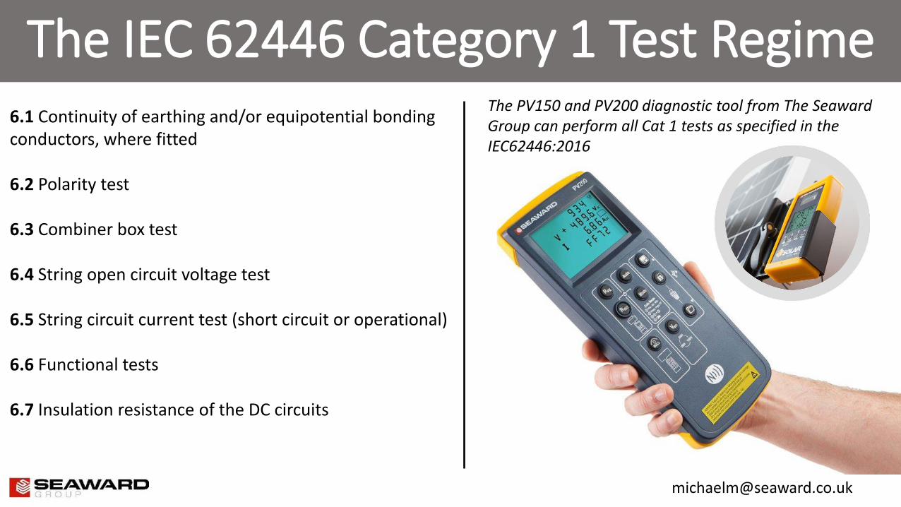
The IEC 62446 Category 1 Test Regime
6.1 Continuity of earthing and/or equipotential bonding conductors, where fitted
6.2 Polarity test
6.3 Combiner box test 6.4 String open circuit voltage test
6.5 String circuit current test (short circuit or operational)
6.6 Functional tests
6.7 Insulation resistance of the DC circuits
The PV150 and PV200 diagnostic tool from The Seaward Group can perform all Cat 1 tests as specified in the IEC62446:2016
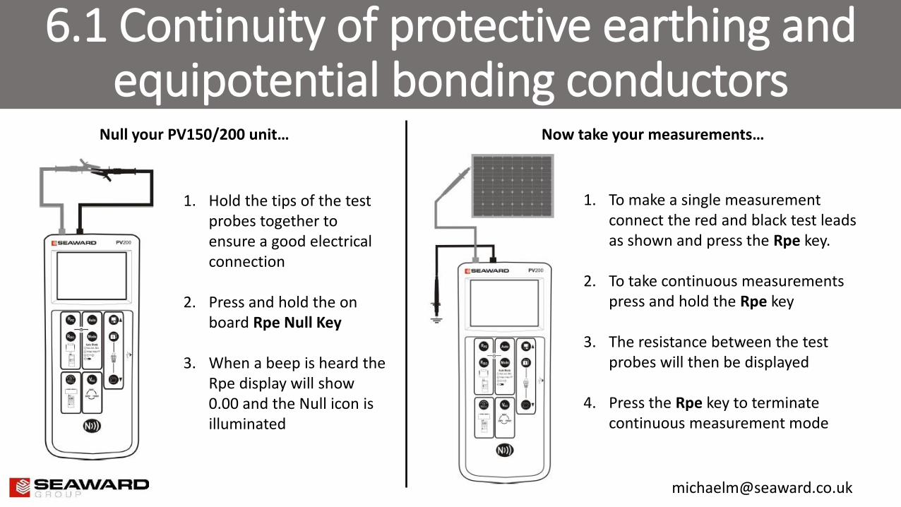
6.1 Continuity of protective earthing and equipotential bonding conductors
1. Hold the tips of the test probes together to ensure a good electrical connection
2. Press and hold the on board Rpe Null Key
3. When a beep is heard the Rpe display will show 0.00 and the Null icon is illuminated
1. To make a single measurement connect the red and black test leads as shown and press the Rpe key.
2. To take continuous measurements press and hold the Rpe key
3. The resistance between the test probes will then be displayed
4. Press the Rpe key to terminate continuous measurement mode
Null your PV150/200 unit… Now take your measurements…
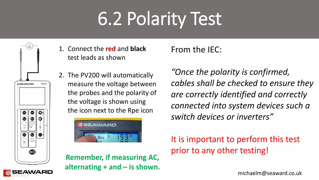
6.2 Polarity Test
1. Connect the red and black test leads as shown
2. The PV200 will automatically measure the voltage between the probes and the polarity of the voltage is shown using the icon next to the Rpe icon
From the IEC: “Once the polarity is confirmed, cables shall be checked to ensure they are correctly identified and correctly connected into system devices such a switch devices or inverters” It is important to perform this test prior to any other testing!
Remember, if measuring AC, alternating + and – is shown.
6.3 PV string combiner box test
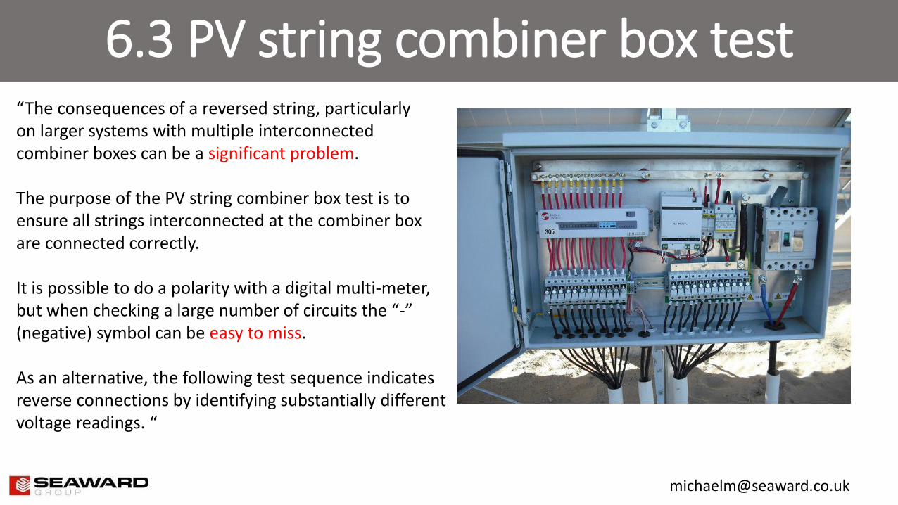
“The consequences of a reversed string, particularly on larger systems with multiple interconnected combiner boxes can be a significant problem. The purpose of the PV string combiner box test is to ensure all strings interconnected at the combiner box are connected correctly. It is possible to do a polarity with a digital multi-meter, but when checking a large number of circuits the “-” (negative) symbol can be easy to miss. As an alternative, the following test sequence indicates reverse connections by identifying substantially different voltage readings. “
6.3 PV string combiner box test
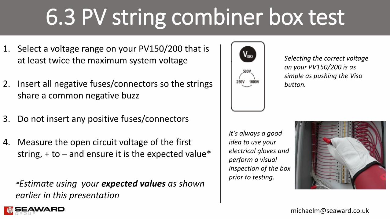
1. Select a voltage range on your PV150/200 that is at least twice the maximum system voltage
2. Insert all negative fuses/connectors so the strings share a common negative buzz
3. Do not insert any positive fuses/connectors
4. Measure the open circuit voltage of the first string, + to – and ensure it is the expected value*
Selecting the correct voltage on your PV150/200 is as simple as pushing the Viso button.
It’s always a good idea to use your electrical gloves and perform a visual inspection of the box prior to testing.
*Estimate using your expected values as shown earlier in this presentation
6.3 PV string combiner box test
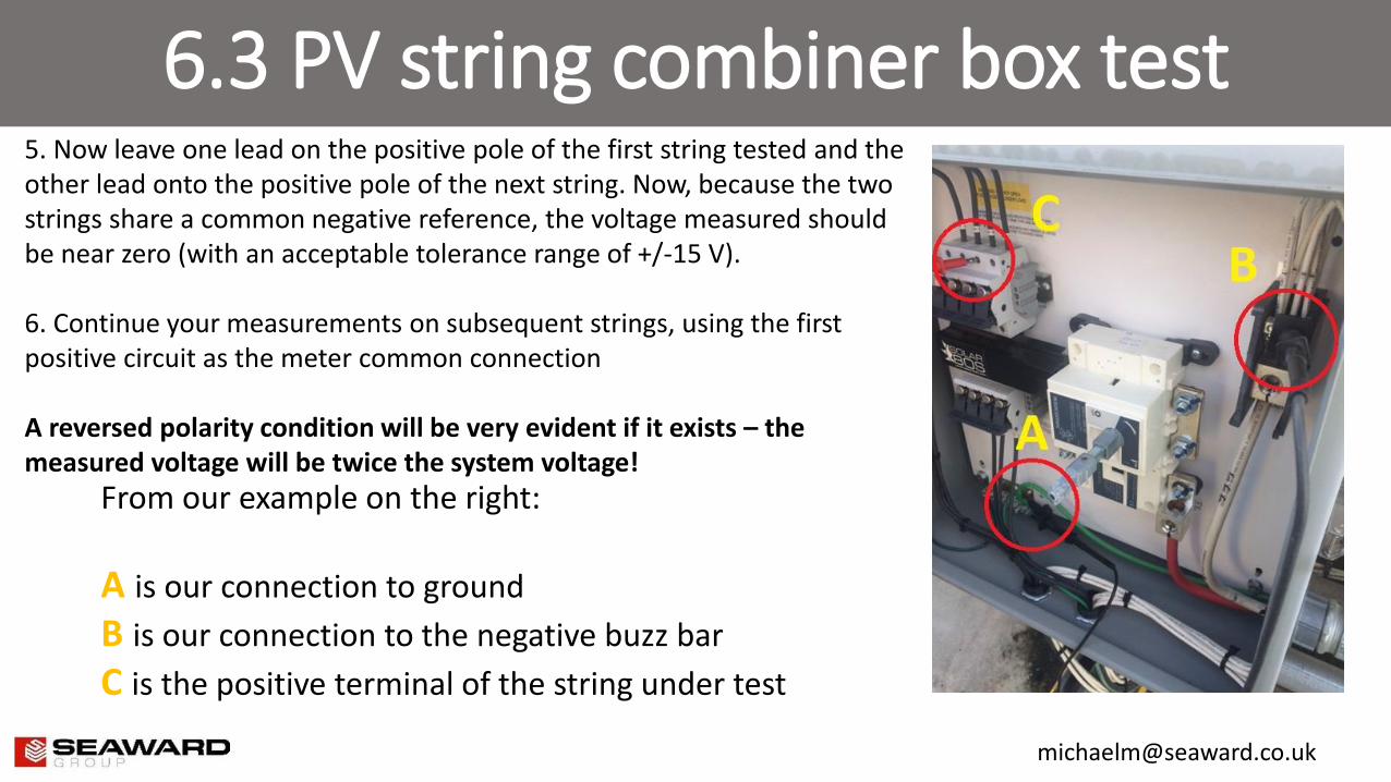
5. Now leave one lead on the positive pole of the first string tested and the other lead onto the positive pole of the next string. Now, because the two strings share a common negative reference, the voltage measured should be near zero (with an acceptable tolerance range of +/-15 V). 6. Continue your measurements on subsequent strings, using the first positive circuit as the meter common connection A reversed polarity condition will be very evident if it exists – the measured voltage will be twice the system voltage!
From our example on the right:
A is our connection to ground
B is our connection to the negative buzz bar
C is the positive terminal of the string under test
6.4 PV string – Open circuit voltage measurement
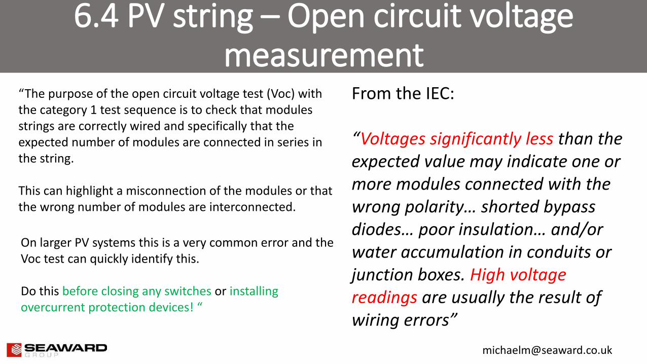
“The purpose of the open circuit voltage test (Voc) with the category 1 test sequence is to check that modules strings are correctly wired and specifically that the expected number of modules are connected in series in the string. This can highlight a misconnection of the modules or that the wrong number of modules are interconnected.
From the IEC: “Voltages significantly less than the expected value may indicate one or more modules connected with the wrong polarity… shorted bypass diodes… poor insulation… and/or water accumulation in conduits or junction boxes. High voltage readings are usually the result of wiring errors”
On larger PV systems this is a very common error and the Voc test can quickly identify this. Do this before closing any switches or installing overcurrent protection devices! “
6.4 PV string – Open circuit voltage measurement
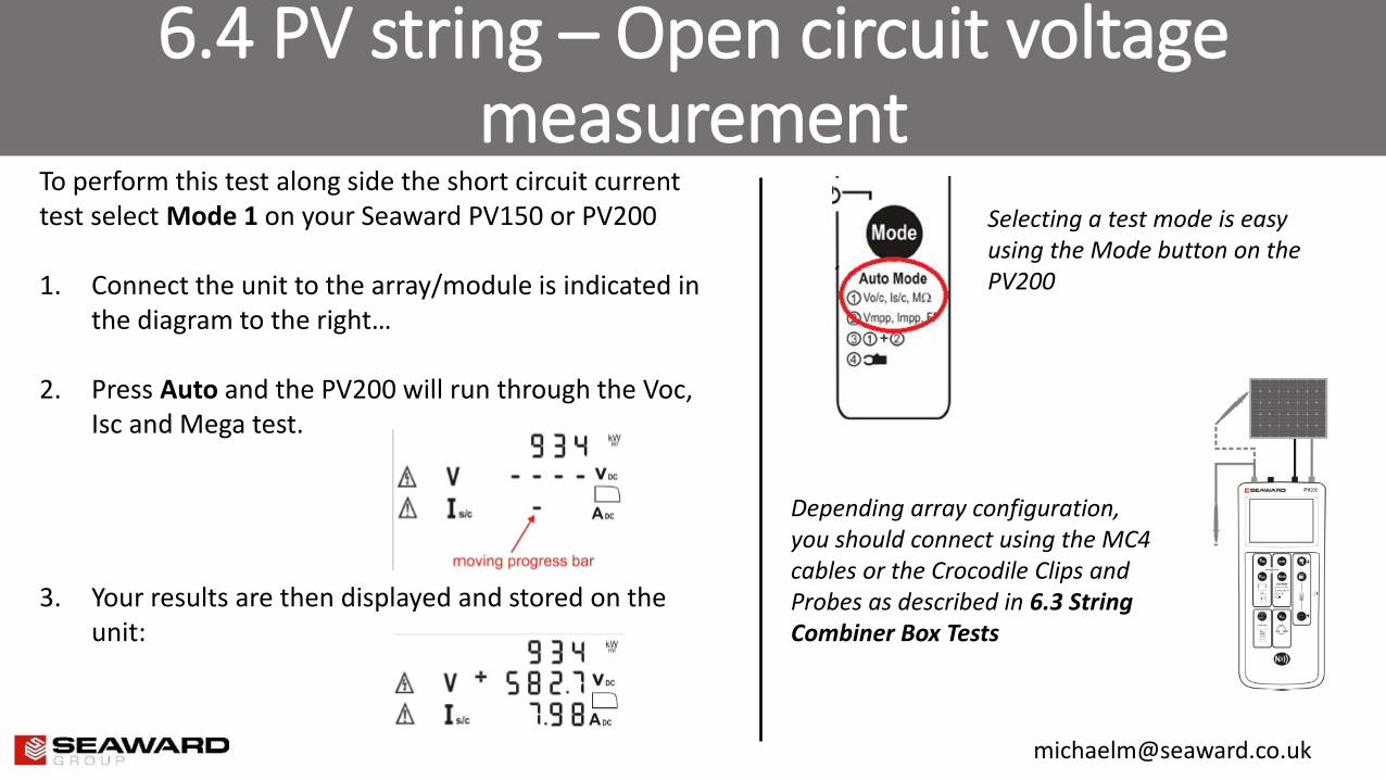
To perform this test along side the short circuit current test select Mode 1 on your Seaward PV150 or PV200 1. Connect the unit to the array/module is indicated in
the diagram to the right…
2. Press Auto and the PV200 will run through the Voc, Isc and Mega test.
3. Your results are then displayed and stored on the unit:
Selecting a test mode is easy using the Mode button on the PV200
Depending array configuration, you should connect using the MC4 cables or the Crocodile Clips and Probes as described in 6.3 String Combiner Box Tests
6.5 PV String – Current Measurement
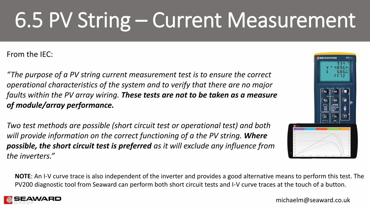
From the IEC: “The purpose of a PV string current measurement test is to ensure the correct operational characteristics of the system and to verify that there are no major faults within the PV array wiring. These tests are not to be taken as a measure of module/array performance. Two test methods are possible (short circuit test or operational test) and both will provide information on the correct functioning of a the PV string. Where possible, the short circuit test is preferred as it will exclude any influence from the inverters.”
NOTE: An I-V curve trace is also independent of the inverter and provides a good alternative means to perform this test. The PV200 diagnostic tool from Seaward can perform both short circuit tests and I-V curve traces at the touch of a button.
6.5.2 String Current Measurement
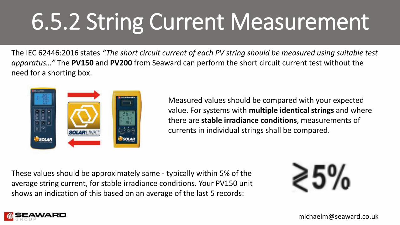
The IEC 62446:2016 states “The short circuit current of each PV string should be measured using suitable test apparatus…” The PV150 and PV200 from Seaward can perform the short circuit current test without the need for a shorting box.
Measured values should be compared with your expected value. For systems with multiple identical strings and where there are stable irradiance conditions, measurements of currents in individual strings shall be compared.
These values should be approximately same - typically within 5% of the average string current, for stable irradiance conditions. Your PV150 unit shows an indication of this based on an average of the last 5 records:
6.5.2 String Current Measurement
The method on the previous slide is applicable during stable irradiance conditions, however what do we do under unstable irradiance conditions, for instance on a cloudy day when we have sporadic shading?
- Delay the testing
- Test using multiple meters, with one meter on a reference string
- An irradiance meter reading or visual appraisal of the sunlight conditions may be used to consider the validity of the current readings*
NOTE: The short circuit current test is intended to detect faults rather than give any indication of performance. System performance measurements are deemed to be part of a Category 2 test regime and are best achieved by performing an I-V curve trace… see our Benefits of I-V Curve Tracing presentation for more details.
For non-stable irradiance conditions the IEC 62446:2016 recommends the following:
6.5.2 String Current Measurement
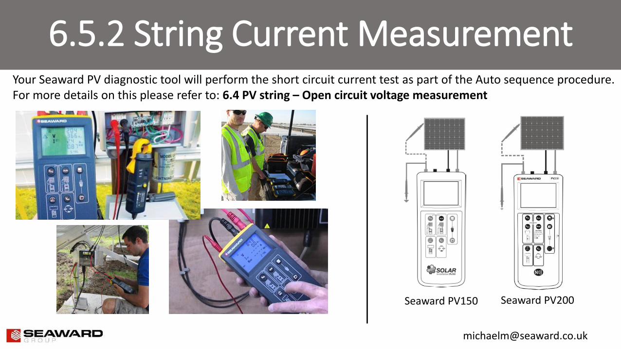
Your Seaward PV diagnostic tool will perform the short circuit current test as part of the Auto sequence procedure. For more details on this please refer to: 6.4 PV string – Open circuit voltage measurement
Seaward PV150 Seaward PV200
6.6 Functional Tests
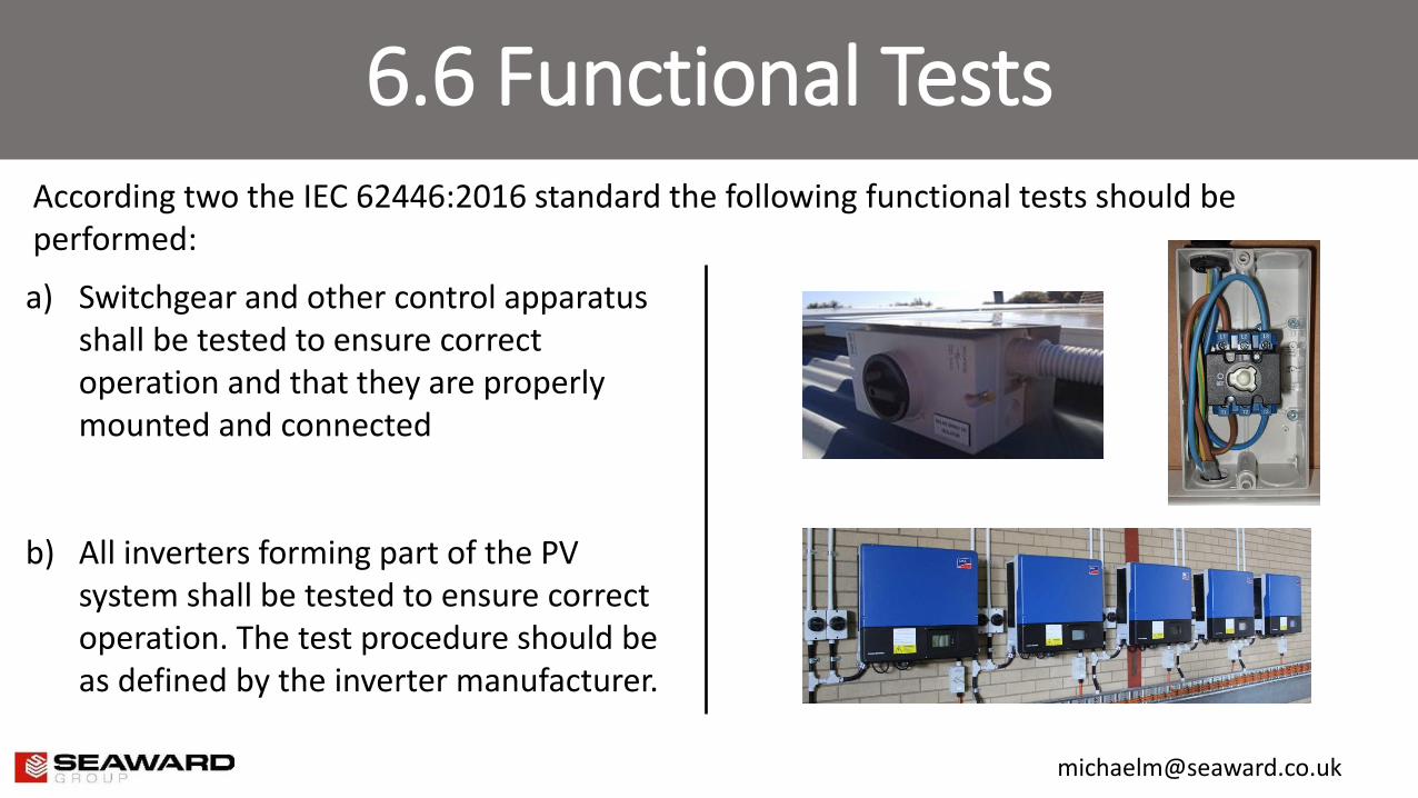
According two the IEC 62446:2016 standard the following functional tests should be performed:
a) Switchgear and other control apparatus shall be tested to ensure correct operation and that they are properly mounted and connected
b) All inverters forming part of the PV system shall be tested to ensure correct operation. The test procedure should be as defined by the inverter manufacturer.
6.7 PV array insulation resistance test
A PV array is an active DC circuit during daylight hours and unlike a conventional AC circuit it cannot be isolated prior to an insulation resistance test.
It is essential therefore to fully understand the procedure before performing the test and implement the following safety measures:
- Limit access to the work area, perhaps by using warning tape or rope - Do not touch and take measures to prevent any other persons touching any metallic surface when
performing the insulation resistance test. This includes the module frame, module laminate and connection terminals
- Whenever the insulation test device is energised, there is voltage in the testing area therefore the equipment you use should have an automatic auto-discharge capacity
- Appropriate PPE should be worn at all times (see the slide at the start of this presentation for more details)
6.7.3 PV insulation resistance test procedure
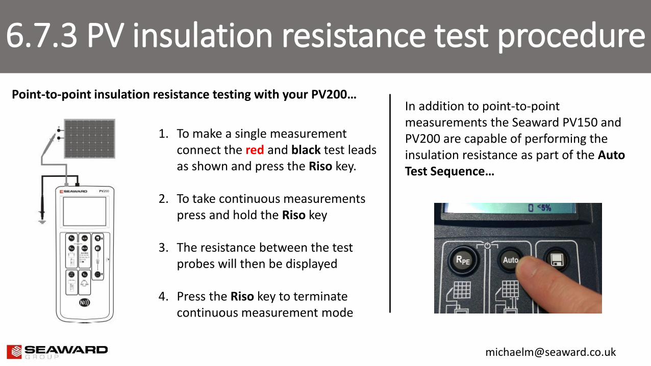
1. To make a single measurement connect the red and black test leads as shown and press the Riso key.
2. To take continuous measurements press and hold the Riso key
3. The resistance between the test probes will then be displayed
4. Press the Riso key to terminate continuous measurement mode
Point-to-point insulation resistance testing with your PV200… In addition to point-to-point measurements the Seaward PV150 and PV200 are capable of performing the insulation resistance as part of the Auto Test Sequence…
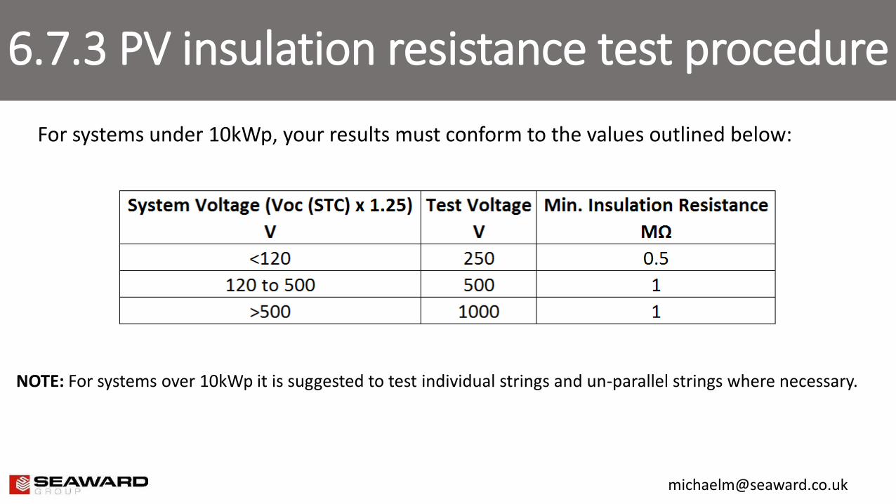
6.7.3 PV insulation resistance test procedure
For systems under 10kWp, your results must conform to the values outlined below:
NOTE: For systems over 10kWp it is suggested to test individual strings and un-parallel strings where necessary.
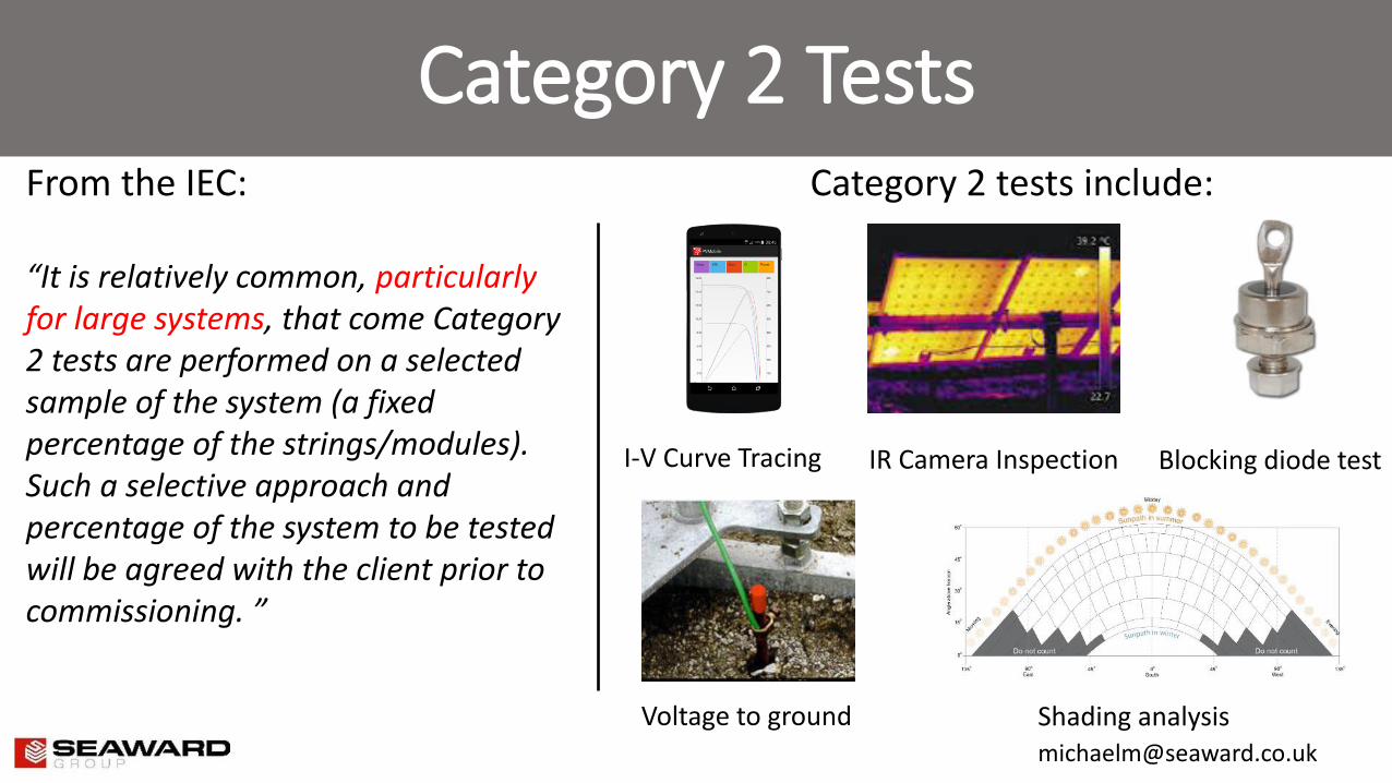
Category 2 Tests
From the IEC: “It is relatively common, particularly for large systems, that come Category 2 tests are performed on a selected sample of the system (a fixed percentage of the strings/modules). Such a selective approach and percentage of the system to be tested will be agreed with the client prior to commissioning. ”
Category 2 tests include:
I-V Curve Tracing IR Camera Inspection
Voltage to ground
Blocking diode test
Shading analysis

World Leading Electrical Test Equipment from Seaward Seaward has over 70 years experience in the design manufacture of market-leading electrical test equipment. Seaward’s unrivalled range of electrical test equipment serves a wide variety of safety testing and precision measurement applications. For 25 years Seaward has been developing market-defining portable appliance testers, software and accessories for the PAT testing market. The Cropico and Clare ranges of precision instruments and industrial electrical test equipment bolster Seaward’s product offering and demonstrate the result of 70 years of technical expertise across a number of industries including manufacturing, utilities and aerospace. The market-defining range of solar PV test equipment makes meeting IEC 62446 and other PV test and documentation requirements faster, safer and easier. From solar site-survey to commissioning tests, PV system maintenance and PV system certification, Seaward Solar has it covered.