42
Quick Start to VHDL Quick Start to VHDL VHDL VHDL V V ery ery H H ard ard D D ifficult ifficult L L anguage anguage !!!!!!! !!!!!!!
| Date post: | 14-Dec-2015 |
| Category: |
Documents |
| Upload: | jaden-kettleson |
| View: | 229 times |
| Download: | 1 times |

Quick Start to VHDLQuick Start to VHDL
VHDLVHDL
VVery ery HHard ard DDifficult ifficult LLanguageanguage
!!!!!!!!!!!!!!

Quick Start to VHDLQuick Start to VHDL
VHDLVHDL
VVeryery High Speed Integrated CircuitsHigh Speed Integrated Circuits
HHardwareardware DDescriptionescription LLanguageanguage

How You can do VHDLHow You can do VHDL
1.Behavior Method1.Behavior MethodSpecify the relationship between inputs Specify the relationship between inputs and outputand output
Y<= (A Y<= (A XORXOR B) B) OROR C C
2. Structural Method2. Structural Method Mapping between Mapping between logical componentslogical components

VHDL FundamentalsVHDL Fundamentals
–Libraries and PackagesLibraries and Packages
–Entity (Data Types)Entity (Data Types)
–ArchitectureArchitecture
–Signals (Data Types)Signals (Data Types)
–OperatorsOperators

Libraries and PackagesLibraries and Packages
Libraries provide a set components and functions Libraries provide a set components and functions that simplify the task of designingthat simplify the task of designing
Packages provide subprograms maybe used in a Packages provide subprograms maybe used in a designdesign
The following is an example of the use of the IEEE The following is an example of the use of the IEEE library and its STD_LOGIC_1164 package:library and its STD_LOGIC_1164 package:
LIBRARYLIBRARY ieee; ieee;USEUSE ieee.std_logic_1164. ieee.std_logic_1164.ALL;ALL;

EntitiesEntities An entity is a specification of the design’s external interfaceAn entity is a specification of the design’s external interface
Entity declarations specify the following:Entity declarations specify the following:1.1. Name of the entityName of the entity2.2. Set of port declarations defining the inputs and outputs to the Set of port declarations defining the inputs and outputs to the
hardware designhardware design
The following is an example of an entity declaration:The following is an example of an entity declaration:
ENTITYENTITY orgate orgate ISISPORTPORT ( (
a : a : ININ STD_LOGIC;STD_LOGIC;b : b : ININ STD_LOGIC;STD_LOGIC;y : y : OUTOUT STD_LOGIC );STD_LOGIC );
ENDEND orgate; orgate;
Port DirectionPort Direction
Port Data TypePort Data Type

PortsPorts Port name choices:Port name choices:
– Always begin with a letterAlways begin with a letter– Case insensitiveCase insensitive
Port direction choices:Port direction choices:
ININ Input portInput portOUTOUT Output portOutput port
Port signal type (suggested) choices:Port signal type (suggested) choices:
– STD_LOGICSTD_LOGIC– STD_LOGIC_VECTOR(<max> STD_LOGIC_VECTOR(<max> DOWNTODOWNTO <min>) <min>)
for 8bit data type : std_logic_vector(7 downto 0)for 8bit data type : std_logic_vector(7 downto 0) – IntegerInteger– RealReal– BooleanBoolean

ArchitecturesArchitectures
An architecture is a specification of the design’s An architecture is a specification of the design’s internal implementationinternal implementation
The following is an example of an architecture The following is an example of an architecture declaration:declaration:
ARCHITECTUREARCHITECTURE a a OFOF orgate orgate ISISBEGINBEGIN
y <= a or b;y <= a or b;ENDEND a; a;

Logical OperatorsLogical Operators
VHDL supports the following logical operators:VHDL supports the following logical operators:
ANDAND OROR XORXOR XNORXNOR NOTNOT NANDNAND NORNOR

Other OperatorsOther Operators VHDL supports the following relational operators:VHDL supports the following relational operators:
= = (Equal)(Equal)/= /= (Not Equal)(Not Equal)<< (Less Than)(Less Than)>> (Greater Than)(Greater Than)
VHDL supports the following mathematical operators:VHDL supports the following mathematical operators:
++ (Addition)(Addition)-- (Subtraction)(Subtraction)** (Multiplication)(Multiplication)// (Division)(Division)AbsAbs (Absolute)(Absolute)**** (Exponentiation)(Exponentiation)

Complete Complete ExampleExample
LIBRARYLIBRARY ieee;ieee;
USEUSE ieee.std_logic_1164.ieee.std_logic_1164.ALL;ALL;
ENTITYENTITY orgate orgate ISISPORTPORT ( (
a : a : ININ STD_LOGIC;STD_LOGIC;b : b : ININ STD_LOGIC;STD_LOGIC;y : y : OUTOUT STD_LOGIC );STD_LOGIC );
ENDEND orgate; orgate;
ARCHITECTUREARCHITECTURE a a OFOF orgate orgate ISISBEGINBEGIN
y <= a or b;y <= a or b;ENDEND a; a;

Start With MaxPlus IIStart With MaxPlus II
Software is used to check, compile and Software is used to check, compile and simulate the VHDL code.simulate the VHDL code.
start MAX+PLUS IIstart MAX+PLUS II

Select Select File File New.New.
SelectSelect Text Editor File.Text Editor File.
Start With MaxPlus IIStart With MaxPlus II

In the new empty window write the VHDL input fileIn the new empty window write the VHDL input file.. LIBRARYLIBRARY ieee;ieee;
USEUSE ieee.std_logic_1164.ieee.std_logic_1164.ALLALLENTITYENTITY orgate orgate ISISPORTPORT ( (
a : a : ININ STD_LOGIC;STD_LOGIC;b : b : ININ STD_LOGIC;STD_LOGIC;c : c : OUTOUT STD_LOGIC );STD_LOGIC );
ENDEND orgate; orgate;
ARCHITECTUREARCHITECTURE a a OFOF orgate orgate ISISBEGINBEGINc <= a or b;c <= a or b;
ENDEND a; a;
Start With MaxPlus IIStart With MaxPlus II

Save the File as VhdSave the File as Vhd , ,Select Select File File Save As.Save As.
Save using the same name of the entitySave using the same name of the entity
Start With MaxPlus IIStart With MaxPlus II

Set project to Current FileSet project to Current File ,Select ,Select File File Project Project Set Project to Current File.Set Project to Current File.
Start With MaxPlus IIStart With MaxPlus II
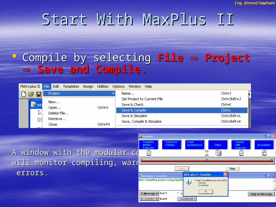
Compile by selecting Compile by selecting File File Project Project Save and Save and Compile.Compile.
A window with the modular compiler, A window with the modular compiler, will monitor compiling, warnings andwill monitor compiling, warnings and errors.errors.
Start With MaxPlus IIStart With MaxPlus II

For simulation:For simulation: Choose Choose FileFile New New, , select select Waveform Editor FileWaveform Editor File, ,
and then click and then click OKOK Select Select Node Node Enter Node from SNF Enter Node from SNF Click on Click on ListList to list the input & output ports to list the input & output ports Select these portsSelect these ports
Start With MaxPlus IIStart With MaxPlus II

Modify the inputsModify the inputs Select Select File File Project Project Save and Simulate Save and Simulate
Start With MaxPlus IIStart With MaxPlus II

library ieee;library ieee;use ieee.std_logic_1164.all;use ieee.std_logic_1164.all;--full_adder--full_adderentity full_adder isentity full_adder isport port ( a,b,cin: in std_logic;( a,b,cin: in std_logic;
sum,cout:out std_logic);sum,cout:out std_logic);end full_adder;end full_adder;architecture full_adderfun of full_adder isarchitecture full_adderfun of full_adder issignal sum1, c1, c2:std_logic;signal sum1, c1, c2:std_logic;beginbegin
sum1 <= a xor b;sum1 <= a xor b;sum <= sum1 xor cin;sum <= sum1 xor cin;c1 <= sum1 and cin;c1 <= sum1 and cin;c2 <= a and b;c2 <= a and b;cout <= c1 or c2;cout <= c1 or c2;
end full_adderfun;end full_adderfun;
22ndnd Complete Complete ExampleExample

SignalsSignals
Signals represent wires and storage Signals represent wires and storage elements within a VHDL designelements within a VHDL design
Signals only be defined inside architecturesSignals only be defined inside architectures Signals are associated with a data typeSignals are associated with a data type

UP2 Education BoardUP2 Education BoardThe board contains:The board contains:
•FLEX® 10KFLEX® 10K FPGA device FPGA device•MAX® 7000MAX® 7000 PLD PLD•One Oscillator One Oscillator •Four Jumpers Four Jumpers •Four Push ButtonFour Push Button•16 LED’S16 LED’S•Four Seven Segment DisplaysFour Seven Segment Displays•Three SwitchesThree Switches•Four ExpansionsFour Expansions

UP2 Education Board UP2 Education Board FLEX® 10KFLEX® 10K FPGA FPGA
• Contains 70,000 gates, 3744 logic elements, Contains 70,000 gates, 3744 logic elements, 4096 register and 18432 RAM bits.4096 register and 18432 RAM bits.
• Connections are made using pass-transistors, Connections are made using pass-transistors, transmission gates, or multiplexers transmission gates, or multiplexers
• Fast in-circuit reconfigurationFast in-circuit reconfiguration
• Volatile memory chip Volatile memory chip

UP2 Education Board UP2 Education Board MAX® 7000MAX® 7000 PLD PLD
• EPROM (Erasable Programmable) TechnologyEPROM (Erasable Programmable) Technology
• Non-volatile memory chip Non-volatile memory chip
• Capacity of 2,500 gates and 128 macro cellsCapacity of 2,500 gates and 128 macro cells
• Each macro cell has a programmable-AND/fixed-OR Each macro cell has a programmable-AND/fixed-OR array as well as a configurable registerarray as well as a configurable register

UP2 Education Board UP2 Education Board OscillatorOscillator
The UP Education Board contains a The UP Education Board contains a
25.175-MHz25.175-MHz crystal oscillator. crystal oscillator.
The output of the oscillator drives a clock input The output of the oscillator drives a clock input
to the to the
EPM7128SEPM7128S device (pin 83) device (pin 83)
FLEX 10KFLEX 10K device (pin 91) device (pin 91)

UP2 Education Board UP2 Education Board JumpersJumpers
The UP Education Board has four three-pin jumpers The UP Education Board has four three-pin jumpers (TDI, TDO, DEVICE, and BOARD)(TDI, TDO, DEVICE, and BOARD)
The jumpers setting to configure:The jumpers setting to configure:
FLEX 10K EPM7128S
UP2 Education Board UP2 Education Board Push ButtonsPush Buttons
Four push buttons: Two are connected toFour push buttons: Two are connected to EPM7128SEPM7128S ((MAX_PB1 & MAX_PB2MAX_PB1 & MAX_PB2 ) and two are connected to ) and two are connected to FLEX 10KFLEX 10K ((FLEX_PB1 & FLEX_PB2FLEX_PB1 & FLEX_PB2 ))
Each push button is pulled-up to 5 V through a 10-KΩ Each push button is pulled-up to 5 V through a 10-KΩ resistor. (Active Low when pressed)resistor. (Active Low when pressed)
MAX_PB1 & MAX_PB2MAX_PB1 & MAX_PB2 can be connected to any input can be connected to any input of the device expansion.of the device expansion.
FLEX_PB1FLEX_PB1 connected to pin 28, and connected to pin 28, and FLEX_PB2FLEX_PB2 connected to pin 29.connected to pin 29.

UP2 Education Board UP2 Education Board LED’sLED’s
Contains 16 LEDs that are pulled-up with a 330-Contains 16 LEDs that are pulled-up with a 330-Ω resistor. Ω resistor.
An LED is illuminated when a logic 0 is applied An LED is illuminated when a logic 0 is applied
to the female header associated with the LEDto the female header associated with the LED

UP2 Education Board UP2 Education Board 7 Segment Display7 Segment Display
Four 7 Segment Displays: Two are connected toFour 7 Segment Displays: Two are connected to EPM7128SEPM7128S and two toand two to FLEX 10KFLEX 10K
Each LED segment of the display can be Each LED segment of the display can be illuminated by driving the connected pin with a illuminated by driving the connected pin with a logic 0 logic 0

UP2 Education Board UP2 Education Board 7 Segment Display7 Segment Display
FLEX 10KFLEX 10K EPM7128SEPM7128S

UP2 Education Board UP2 Education Board SwitchesSwitches
Three 8 switches: Two are connected toThree 8 switches: Two are connected to EPM7128SEPM7128S (MAX_SW1 & MAX_SW2 Switches)(MAX_SW1 & MAX_SW2 Switches) and one toand one to FLEX 10K (FLEX_SW1 Switches)FLEX 10K (FLEX_SW1 Switches)
An input pin is set to logic 1 when the switch is open An input pin is set to logic 1 when the switch is open and set to logic 0 when the switch is closed.and set to logic 0 when the switch is closed.
MAX_SW1 & MAX_SW2 SwitchesMAX_SW1 & MAX_SW2 Switches can be connected can be connected to any input of the device expansionto any input of the device expansion
FLEX_SW1 SwitchesFLEX_SW1 Switches are connected as following:are connected as following:

UP2 Education Board UP2 Education Board SwitchesSwitches

UP2 Education Board UP2 Education Board ExpansionsExpansions
MAX_EXPANSIONMAX_EXPANSION FLEX_EXPAN_AFLEX_EXPAN_A, , FLEX_EXPAN_BFLEX_EXPAN_B, and , and FLEX_EXPAN_CFLEX_EXPAN_C are are dual rows of 0.1-inch spaced holes for accessing dual rows of 0.1-inch spaced holes for accessing signal I/O pinssignal I/O pins

UP2 Education Board UP2 Education Board ExpansionsExpansions

UP2 Education Board UP2 Education Board ExpansionsExpansions

UP2 Education Board UP2 Education Board ExpansionsExpansions

UP2 Education Board UP2 Education Board ExpansionsExpansions

Select Select Assign Assign DeviceDevice
To assign the chip that will be used to configure To assign the chip that will be used to configure the design. Here the design. Here FLEX10KFLEX10K is assigned with the is assigned with the chip number chip number EPF10K70RC240-2EPF10K70RC240-2 that is written on that is written on the chip.the chip.
Programming With MaxPlus IIProgramming With MaxPlus II

Select Select Assign Assign Pin/Location/ChipPin/Location/Chip
Programming With MaxPlus IIProgramming With MaxPlus II
Click SearchClick List

Programming With MaxPlus IIProgramming With MaxPlus II
Pin 28 is Flex_PB1Pin 29 is Flex_PB2Pin 41 is Flex switch1Pin 6 is (a) of 7seg1Pin 17 is (a) of 7seg2

Programming With MaxPlus IIProgramming With MaxPlus II Select Select Mxx+Pluss II Mxx+Pluss II ProgrammerProgrammer
Select Select JTAG JTAG Multi-device JTAG chain Multi-device JTAG chain so that a checkmark so that a checkmark appears to the left of the option. appears to the left of the option.
Hit the Hit the Select programming FileSelect programming File button and select button and select full_adderfull_adder.sof.sof..
Click Click OKOK, then click the , then click the ADDADD button and the new filename should button and the new filename should move into the list in the inner window. move into the list in the inner window.
Select the Select the Detect JTAG Chain InfoDetect JTAG Chain Info button. The system should button. The system should respond with “respond with “JTAG chain information confirmed by hardware checkJTAG chain information confirmed by hardware check”. ”.
If not, double check cables, power, jumpers, and make sure you have If not, double check cables, power, jumpers, and make sure you have the correct file name and chip listed in the inner window. the correct file name and chip listed in the inner window.
Click Click OKOK to exit the to exit the JTAG Multi-device Setup JTAG Multi-device Setup window. window.

The The configureconfigure button in the programming window should button in the programming window should now be highlighted. now be highlighted.
Click on the Click on the configureconfigure button to download to the board. button to download to the board.
Just a few seconds are required to download. If download Just a few seconds are required to download. If download is successful, a window with is successful, a window with Configuration CompleteConfiguration Complete is is displayed - clickdisplayed - click OK. OK.
If the If the configureconfigure button is not highlighted, try button is not highlighted, try OptionOption Hardware Setup Hardware Setup from the pull-down window. confirm the from the pull-down window. confirm the port settings and click port settings and click OK. OK. Also confirm that the JTAG Also confirm that the JTAG setup dialog information is correct. If you still have setup dialog information is correct. If you still have problems confirm that the printer port BIOS settings ESP or problems confirm that the printer port BIOS settings ESP or EPP mode. EPP mode.
Programming With MaxPlus IIProgramming With MaxPlus II


