Page 1
Lawrence Berkeley National Laboratory
Cat Code
SU3343 QXF MATERIALS
- CABLE
Serial #
SU-1004-0963 Rev
1.6
Author(s)
H. Higley, A. Lin, I. Pong Department
ATAP Location
Berkeley Date
2016 10 06
Page 1 of 25
Title
QXF Cable Fabrication Procedure
QXF 2nd Gen. Cable
Fabrication Procedure Cable #: ……
Date : ……
Fill this document using BLUE PEN only
Paste Cable Barcode here
Page 2
2
Contents
QXF CABLE FABRICATION PROCEDURE ............................................. 1
Cable #: …………… .................................................................................................... 1 Date : …………… .................................................................................................... 1
I. WIRE INFORMATION .......................................................................... 3
I.1 Strand Map .................................................................................................. 3
I.2 Excel file “Respool Log” .............................................................................. 4
I.3 Re-spooling the un-annealed/annealed wires .............................................. 5
II. PREPARATION OF THE CABLING MACHINE ............................... 8
II.1 Spools and brakes ........................................................................................ 8 II.2 Roll information ........................................................................................... 9
II.3 Mandrel information ................................................................................. 11
II.4 Stainless-steel core ..................................................................................... 13 II.5 Brakes ......................................................................................................... 14
II.6 Start Up Check List ................................................................................... 15
III. TUNING OF THE CABLING MACHINE PARAMETERS .............. 17
IV. AFTER A CABLE RUN ........................................................................ 20
IV.1 Verification of the wire tension.................................................................. 20
IV.2 Leftover stainless steel core and strands ................................................... 21
IV.3 Stow away parts such as mandrel (with cover) if applicable .................... 21
V. DOCUMENTATION ............................................................................. 22
V.1 Update the Master Database ..................................................................... 22 V.2 Producing the Summary Report ............................................................... 24
VI. FINAL CONTROL POINT .................................................................. 25
Page 3
3
I. Wire Information
I.1 Strand Map
The Strand Map should be pasted below by the Scientist/Engineer.
From Scientist/Engineer’s name + signature and date:
Commented [IP1]: Add here the colour length target.
Page 4
4
I.2 Excel file “Respool Log”
ATPP
The Respool Log file should be created from the Strand Map in the
Master Database by the Scientist/Engineer and provided to the
technician.
Scientist/Engineer’s name + signature and date:
……………………………………………..
Page 5
5
I.3 Re-spooling the wires
Task I.3 Start Date and Time: _________________________________
Verify that there are 40 barcode labelled Al spools and spool brakes
with wires securing the bolts.
Verify that the wires to be re-spooled have a correct barcode
reflecting their un-annealed/annealed status. Weigh if necessary to
verify the approximate wire length, or respool to verify accurately
in the case that the length is critical.
Repeat the following steps for each of the 40 spools.
Place an Al spool onto the re-spooling machine.
Scan into the Excel file “Respool Log”
the ID of the strand
the ID of the Al spool
the ID of the spool brake
Verify that the KEYANCE dual-axis micrometer and the computer
for diameter data collection are turned on.
[This is an empty box]
Page 6
6
For every new payout spool as well as at any point of suspicion,
measure both 1.000 mm and 0.500 mm gauge pins (five times
each). Make sure the optical micrometer gives an accurate reading.
Report any irregularities or damage of the gauge pins.
These measurements should be recorded in the file.
Set the optical micrometer sampling frequency to 0.3 m, or record
the actual sampling frequency used here:
..……………………………..
Set the footage counter to zero.
Start re-spooling. Make sure the wire is uniformly distributed along
the length of the Al spool.
For the first re-spool from a payout, record in the Excel file
“Respool Log” the length of wire on the original spool.
For the first re-spool from the first payout, colour the first 30 m and
the last 30 m with a blue sharpy felt pen. Record in the Excel file
“Respool Log” the colour applied.
For the first re-spool from another selected payout, colour the first
30 m green and the last 30 m red. Record in the Excel file “Respool
Log” the colour applied correctly according to the Al strand spool
Hub/Top position.
For the subsequent re-spools from the same payout, simply check
that the length agrees with the specified length shown in the Excel
File “Respool Log” and that the ‘number of respools to go’ is NOT
zero.
[This is an empty box]
Page 7
7
Cross-check the KEYANCE dual-axis optical micrometer with both
1.000 mm and 0.500 mm gauge pins when the payout spool is
changed and also at the end.
In the laptop that is connected to the optical micrometer, in the
appropriate folder generate a new file and name it as:
[Barcode of the Wire]_[yyyymmdd]_[Operator Initials]_[Length]
Save the file which contains the wire diameter information.
A single file may be used for a large payout spool.
Task I.3 Finish Date and Time: _________________________________
Page 8
8
II. Preparation of the cabling machine
Tasks II.1 to II.4 can be carried out in some flexible order if necessary. For this reason,
the start and finish date and time of each task should be recorded.
II.1 Spools and brakes
Task II.1 Start Date and Time: _________________________________
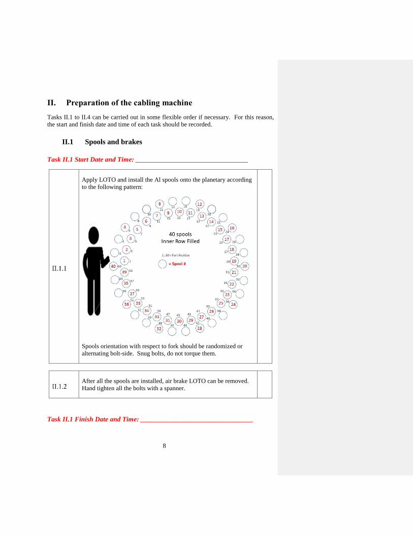
Apply LOTO and install the Al spools onto the planetary according
to the following pattern:
Spools orientation with respect to fork should be randomized or
alternating bolt-side. Snug bolts, do not torque them.
After all the spools are installed, air brake LOTO can be removed.
Hand tighten all the bolts with a spanner.
Task II.1 Finish Date and Time: _________________________________
Page 9
9
II.2 Roll information
Task II.2 Start Date and Time: _________________________________
NP
Inspect the vertical and horizontal rolls and report to the
Scientist/Engineer:
the inspector
the inspection date
the inspected width and diameter in mm to 3 decimal places
the inspected angle in degrees (°) to 3 decimal places
the roll finish where appropriate
any other comments
and the quality (usable or otherwise)
The vertical rolls are assigned by default as given in Table 1.
The horizontal rolls selection is to be verified by the
Scientist/Engineer.
Table 1 – Vertical rolls and roll bearings information
Specified Ref. Info Check if Ok
Top roll ID # 91 (2017 12 08)
Width: 18.062 mm
Angle: 0.452°
Diameter: 142 mm
Bottom roll ID # 92 (2017 12 08)
Width: 18.057 mm
Angle: 0.452°
Diameter: 142 mm
Top roll bearing ID # 91A
91B
Bottom roll bearing ID
#
92C
92D
Commented [IP2]: These are autofilled for convenience. The
rolls and bearings ID’s do not form part of the procedure, but they are
checked at II.6 ATPP.
Page 10
10
Before installing the top and bottom rolls verify the edge rolls (or
horizontal rolls) are open.
Install the rolls on the Turkshead. (For reference, minor edge roller
gap for alignment is ~1.462 mm or ~0.0575”; major edge roller gap
is ~1.588 mm or 0.0625”.)
Details of the location of the roll bearing are given in Figure 1.
Figure 1 – Identification of the roll bearing location.
[This is an empty box]
Tighten the bolt of the drive shaft.
Torque: 4-20 set screw “snug”.
Verify that the major edge is on the ‘High Bay’ side.
Replace the cover plates.
Task II.2 Finish Date and Time: _________________________________
AB
C D
Page 11
11
II.3 Mandrel information
Task II.3 Start Date and Time: _________________________________
Select the mandrel given in Table 2.
Table 2 – Mandrel information
Specification Check
Mandrel ID # 27i7683-B (modified 2017 09 05)
Mandrel surface finish CLEAN
Mandrel tip width 17.35 mm
Mandrel tip thickness 0.73 mm
Mandrel tip angle + 3º
Mandrel slot location Biased towards major edge
Mandrel slot width 12.1 mm
Commented [IP3]: These are autofilled for convenience. The
mandrel ID does not form part of the procedure, but it is checked at II.6 ATPP.
Page 12
12
NP
(conditional)
Inspect the mandrel, and report to the Scientist/Engineer if any of
the following items are modified:
the inspector
the inspection date
the inspected tip width and thickness in mm to 1 decimal
place
the inspected tip angle in degrees (°)
the slot width in mm to 1 decimal place and the slot
position.
any other comments
and visual inspection for defect (usable or otherwise)
Cover the mandrel tip with a cover.
Install the mandrel on the machine (keep the mandrel tip cover).
Align the mandrel (keep the mandrel tip cover).
Task II.3 Finish Date and Time: _________________________________
Page 13
13
II.4 Stainless-steel core
Task II.4 Start Date and Time: _________________________________
Verify the core width and thickness meet specifications:
Width = 12.0 ± 0.3 mm and Thickness = 0.0254 mm.
The barcode ID is
Install the core on the cabling machine so that it pays out in the anti-
clockwise direction when viewed from above. Pay attention not to
let the core slip (uncoil vertically) while installing.
Verify the core brake tension (target: 0.25 kg)
Actual: …………………………………………..
Task II.4 Finish Date and Time: _________________________________
In the Excel File “Respool Log”,
Scan the barcode of the brake in the stainless steel core spool, and
the barcode on the stainless steel core spool itself.
Page 14
14
II.5 Brakes
Open the Excel File “Respool Log”,
Starting from the fork #1 scan the barcodes of all the Capstan
brakes. If there is no brake, scan “empty” from the fork (inside of
the fork).
Still in the Excel File “Respool Log”,
Starting from the fork #1 scan all the Al spools. If there is no spool,
scan “empty” from the fork (inside of the fork).
Still in the Excel File “Respool Log”,
After zero-ing the gauge at horizontal position, measure the wire
tension due to the Spool+Capstan brakes (target 5.8 kg). Record the
values (‘Total Tension before Cable Run”) in the Excel File
“Respool Log”.
Adjust the tension to 5.8 kg if necessary and record the measured
values.
String the wires.
NP When all the wires are strung, save and send a copy of the Excel
File “Respool Log” to the Scientist/Engineer.
Page 15
15
II.6 Start Up Check List
Go through the check list in Table 3.
Table 3 – QXF Cable run start-up check list.
Specification check
Cable pitch length Value 109 mm
Machine setting BF 1-5/8
Planetary wire twist
Value -0.57
# of teeth Drive 13
# of teeth Driven 54
Cable lay direction and pitch
Left lay (so that the wires follow
the same rotation as a left-hand
screw thread).
Mandrel Aligned
Verify edge Rolls position Rolls closed
Pre-load Torque TBD
Mandrel position (pinch point) 1x – 3x wire diameters
Wire path check
Spool # verification 40
Lubricant type 4BR
Lubricant flow rate 3 drops/pitch length at speed,
sufficient in tank
Wire detector ON
Core detector ON
Bias core toward major edge?
Make sure the battery of the core detector is still good.
Page 16
16
Make sure the chain for the planetary motion of the spools is in
place and in good condition.
ATPP
Stop work and obtain authorization before proceeding.
Scientist/Engineer’s name + signature and date:
……………………………………………..
Page 17
17
III. Tuning of the cabling machine parameters
Verify that the CME machine has been calibrated using the
reference gauge block for thickness, width, and keystone angle.
Side pressure should be set at 20 psi and transverse pressure at
17 MPa. The tension on the cable when measurements are made
must be less than 60 lb.
Name Technician 1: ……………………………………………….
Name Technician 2: ………………………………………………..
If CME computer crashes during cable run do not stop the run.
Locate LARP/AUP-approved reels with a minimum hub diameter
of 12 inches. Install the pick-up reel so that the spool flanges are
vertical (axis is horizontal).
Turn on the core detector and the wire detector.
Make 1-2 metres of cable.
Before cutting the cable make sure the final length of the cable is
greater than the required minimum.
Measure the 2 m sample cable width, thickness and keystone angle
using the CME machine.
Measurement performed every 6”.
Page 18
18
For reference, the dimension specifications are::
Width: 18.15 mm ± 50 μm
Thickness: 1.525 mm ± 10 μm
Keystone angle: 0.40º ± 0.10°
Cable lay direction: Left
Cable lay pitch: 109 mm ± 3 mm
For each production unit, ask the scientist/engineer if the following
tests are required. Perform the tests according to US HiLumi Doc
74 and the appropriate procedures.
Metallographic sample check (≤15% sheared triplet
subelements)
Ten-stack measurements (within 8 μm agreement with
CME)
Cable residual twist test (≤ 150°/m)
Cable surface inspection (clean and free from chips,
roughness, sharp edges or burrs, surface uniform to 25% of a
single wire diameter, no broken wires or crossovers)
Adjust, if necessary, the cabling machine parameters in consultation
with the Scientist/Engineer and repeat the steps above. Record any
modifications made to the cabling machine parameters in the Excel
File “QXF Template”.
ATPP
When the cable dimensions are within specification:
Stop work and obtain authorization before proceeding.
Scientist/Engineer’s name + signature and date:
……………………………………………..
Page 19
19
Resume machine operation and begin production run.
CME every 3 m. Wind the cable such that there are no crossovers.
Filler cord may be used at the reel flanges so the cable will lie flat.
Cable spooling direction is specified as follows:
Note the length fabricated during steady state production
……………………………………………..metres
At the end of the run, wrap cling film to protect the cable surface.
Label the spool.
ATPP
Are samples to be taken?
YES NO
If the answer is YES, the Scientist/Engineer needs to indicate the
number of pieces and the length of each piece here:
(Note: US HiLumi Doc 74 requires a 3 m long sample (“Cable Test
Specimen”) from one end of every production run and an archival
sample, minimum of 3 m, adjacent to the Cable Test Specimen.)
Scientist/Engineer’s name + signature and date:
……………………………………………..
Label all the samples appropriately, including identifying/labelling
the strands for extracted measurements if required.
Page 20
20
IV. After a Cable Run
IV.1 Verification of the wire tension
Re-measure the wire tension due to the Spool+Capstan brakes.
Record the values (‘Total Tension after Cable Run”) in the Excel
File “Respool Log”.
NP
Send the Excel File “Respool Log” and report any discrepancy of
more than 0.5 kg before/after the cable run to the
Scientist/Engineer.
Page 21
21
IV.2 Labelling of cable, stainless steel core, and strands
This part may be carried out later if instructed by the Scientist/Engineer.
Add label to the cable spool and enter into inventory.
Print a barcode label with an increased use count from the Master
Database for the stainless steel core. Archive usable leftover
stainless steel core appropriate and discard unusable stainless steel
core.
Print barcode labels for cable samples from the Master Database.
Where appropriate, in the cable sample for extracted strands, mark
the major edge with black ink, then open up about 2 pitch lengths
and label all the strands with barcode labels.
Print barcode labels for leftover strands from the Master Database.
Label. Record the tension and length in the respool log, and archive
the leftover strands.
IV.3 Stow away parts such as mandrel (with cover) if applicable
Page 22
22
V. Documentation
V.1 Update the Master Database
This part may be carried out by the Scientist/Engineer.
In the sheet ‘Wire Inventory’ in the Master Database
Update the use of the strands that went into the cable
Update the storage location of any remaining strands from
re-spooling.
In the sheet ‘Cable Inventory’ in the Master Database
Update the cabling parameters and all other relevant
information according to the working Excel File “QXF
Template”.
Update all the NP information, including the Rolls, the
Mandrel, and the stainless steel core.
Update the storage location and use of all the cable sections.
In the sheets ‘SS Core Delivered’, ‘Mandrel Log’, and ‘Spool Log’
in the Master Database
Update the relevant data from the NP reports.
In the sheet ‘Spool Map’ in the Master Database
Copy the data from the sheet ‘Bay Position Map’ in the
Excel File “Respool Log” and ‘paste value’ to a new line.
Page 23
23
In the Excel File “Al Spools and Brakes Log”
Update the Al spools, spool brakes, and Capstan brakes
information if necessary.
Page 24
24
V.2 Producing the Summary Report
Open the Excel File “QXF Template”.
If the strands were annealed, import the annealing chart and
relevant details from the HT Scheduler to the sheet ‘Annealing
Data’ in the Excel File “QXF Template”.
Import the CME data to the sheet ‘CME Data’ in the Excel File
“QXF Template”.
Validate data and complete any missing information in the sheet
‘Summary’ in the Excel File “QXF Template”.
Save the Excel File “QXF Template” and export in the appropriate
format (PDF or printing) according to requirements from the
Scientist/Engineer for review and approval.
Page 25
25
VI. Final Control Point
Complete the following information
Date of cable fabrication completion (YYYY-MM-DD):
………………………….………………………….
Cabling run performed by (name, signature, and date):
………………………………………..
Document Reviewed by (name, signature, and date):
…………………………………………………
Scan a copy of every page of this procedure after VI.1.1 is
completed, email the PDF file to the Scientist/Engineer, the person
responsible for uploading the file to the DCC server, and the Cable
Task Leader (if not the same person).
End of document.