R E O R T R ESUMES ED 015 650 THE OVERHEAD PROJECTOR IN THE PHYSICS LECTURE. BY- EFFENSTEIN, WALTER RENSSELAER POLYTECHNIC INST., TROY, N.Y. EDRS PRICE MF-$0.50 HC-$2.60 63F. EM 004 024 PUB DATE DEC 61 DESCRIPTORS- *OVERHEAD PROJECTORS, *COLLEGE INSTRUCTION, *PHYSICS, *LECTURE SOME SUCCESSFUL APPLICATIONS OF OVERHEAD PROJECTORS THE PHYSICS LECTURE HALL AT RENSSELAER POLYTECHNIC INSTITUTE ARE DESCRIBED--(1) PRODUCTION AND USE OF TRANSPARENCIES, (2) THE OVERHEAD PROJECTOR IN THE DEMONSTRATION LECTURE, (3) BREAD-BOARD FOR ELECTRICAL CONNECTIONS, AND (4) AN X-4 PLOTTER FOR THE OVERHEAD PROJECTOR. (MS)
Transcript
R E O R T R ESUMESED 015 650THE OVERHEAD PROJECTOR IN THE PHYSICS LECTURE.
SOME SUCCESSFUL APPLICATIONS OF OVERHEAD PROJECTORS
THE PHYSICS LECTURE HALL AT RENSSELAER POLYTECHNIC INSTITUTE
ARE DESCRIBED--(1) PRODUCTION AND USE OF TRANSPARENCIES, (2)
THE OVERHEAD PROJECTOR IN THE DEMONSTRATION LECTURE, (3)
BREAD-BOARD FOR ELECTRICAL CONNECTIONS, AND (4) AN X-4
PLOTTER FOR THE OVERHEAD PROJECTOR. (MS)
Cr
40A ,Ls\
do By .
M
C3 Walter Eppensteinco
UJ
THE OVERHEAD PROJECTOR IN THE PHYSICS LECTURE
EM 004024
RENSSELAER POLYTECHNIC INSTITUTE TROY, NEW YORK
THE OVERHEAD PROJECTOR IN THE PHYSICS LECTURE
Walter Eppenstein
Department of Physics
U.S. DEPARTMENT OF HEALTH, EDUCATION & WELFARE
OFFICE OF EDUCATION
THIS DOCUMENT HAS BEEN REPRODUCED EXACTLY AS RECEIVED FROM THE
PERSON OR ORGANIZATION ORIGINATING iT. POINTS OF VIEW OR OPINIONS
STATED DO NOT NECESSARILY REPRESENT OFFICIAL OFFICE OF EDUCATION
POSITION OR POLICY.
Under Grants from the
Course Content Improvement Section
of the
NATIONAL SCIENCE FOUNDATION
Rensselaer Polytechnic Institute
Troy, New York
December 1961
Fti
--...10111111
G
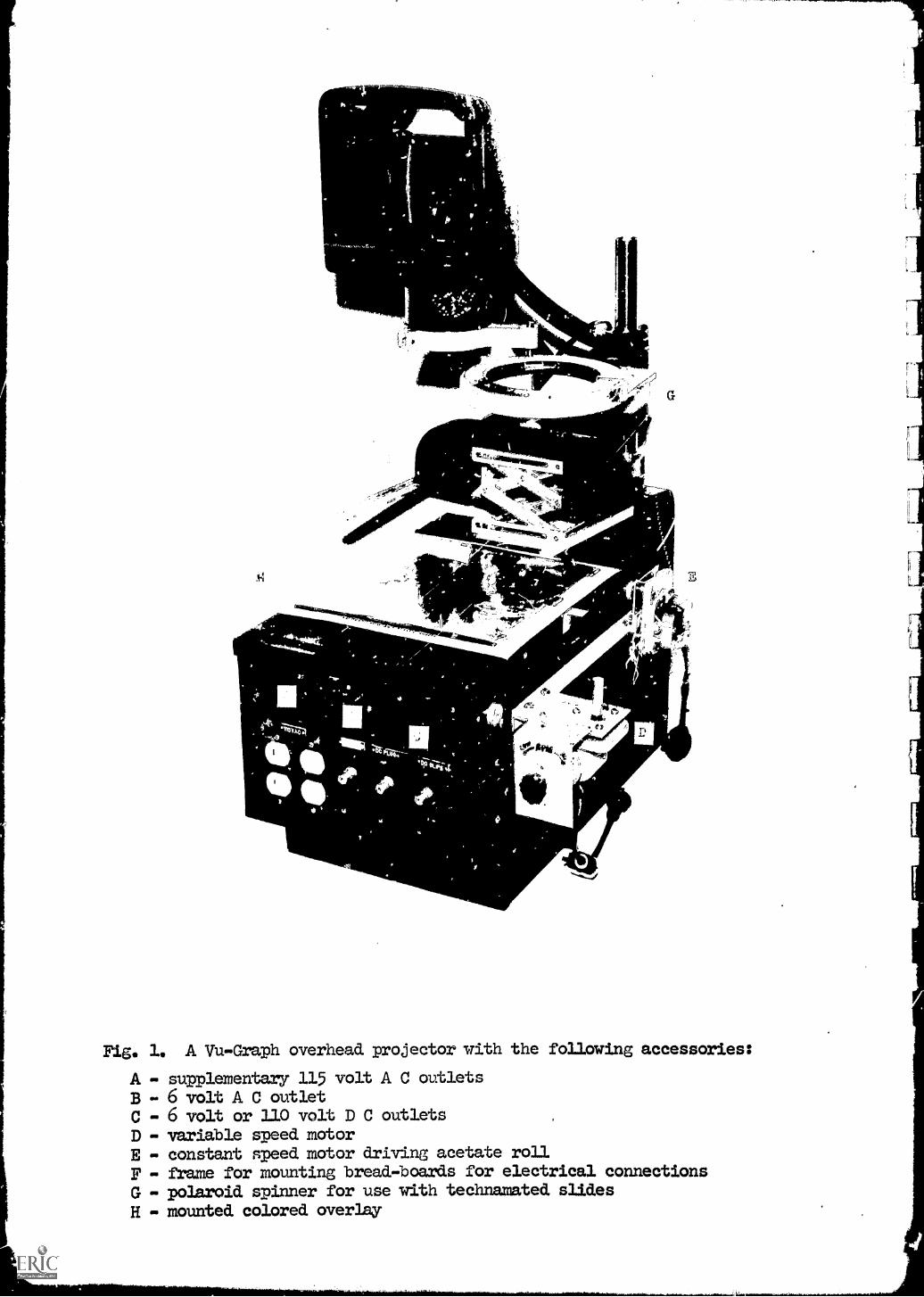
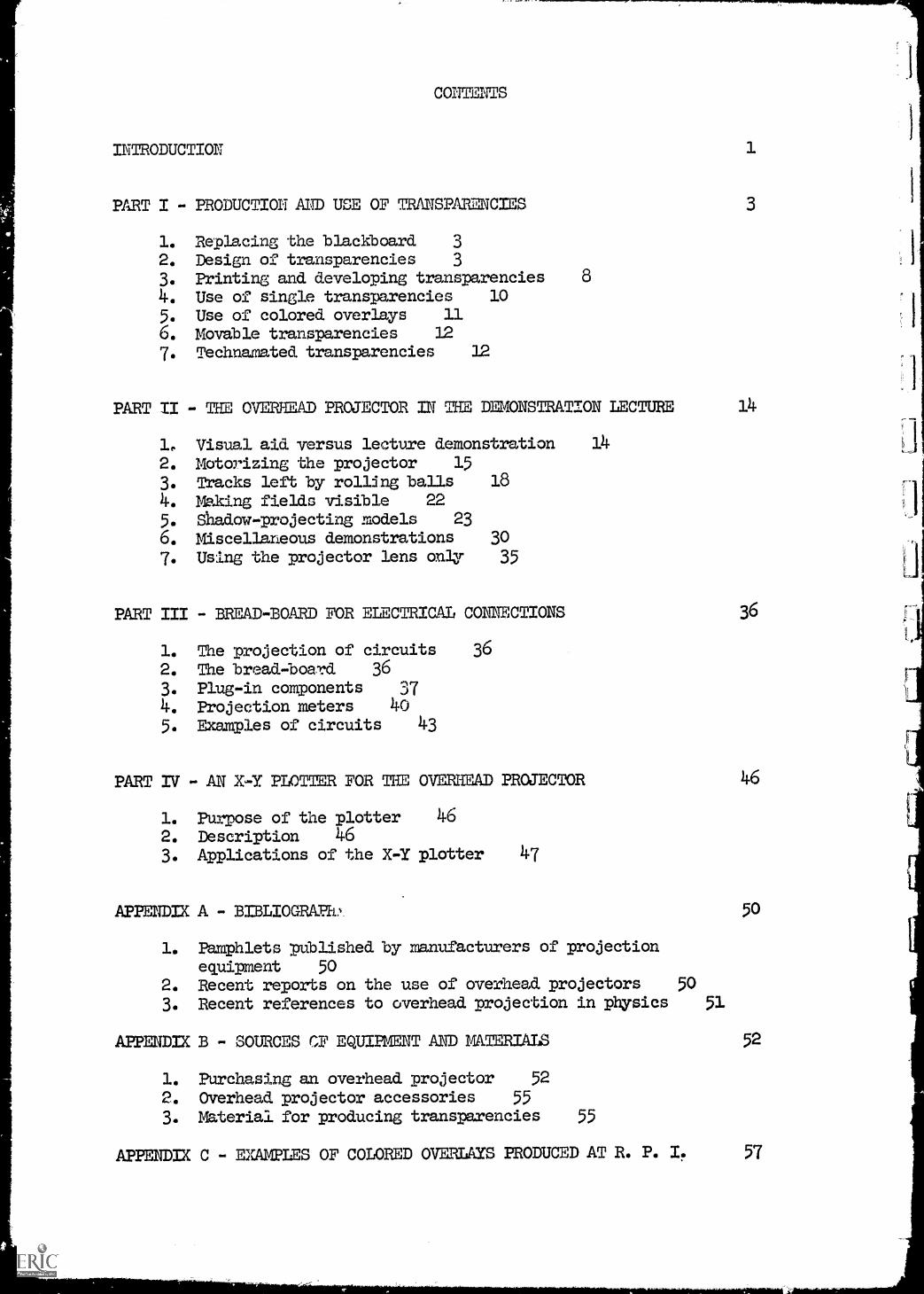
Fig. 1. A Vu -Graph overhead projector with the following accessories:
A - supplementary 115 volt A C outletsB - 6 volt A C outletC - 6 volt or 110 volt D C outletsD - variable speed motorE - constant speed motor driving acetate rollF - frame for mounting bread-boards for electrical connectionsG - polaroid spinner for use with technamated slides
H - mounted colored overlay
PREFACE
With the recent interest in overhead projectors for teaching at all
level 131 it became evident that this very efficient optical system is more
than a replacement for the blackboard. Wherever science lectures are given
to large groups of students, working models as well as actual demonstrations
can be projected effectively.
In this report, some examples of the applications of overhead projectors
are presented. It is our hope that our successful use of overhead projectors
in the teaching of physics will inspire others to develop their own
accessories and demonstrations. We expect that an exchange of ideas willtake place, with the Visual Aids Committee of the American Association ofPhysics Teachers acting as a clearance house, and resulting in a number of
notes or articles in the American Journal of Physics and the new Demonstration Source Book now in preparation. We would welcome any suggestions
along these lines or comments on the report itself.
The work outlined in the following pages, and indeed this report,
would not have been possible without the financial assistance of the National
Science Foundation.
The author also wishes to thank all those who have contributed to this
project. Mt.Richard Heavers and Mr. Stuart N. Crouse have helped to design
various models. Professor William L. Millard and Mr. R. K. LeVan of theOffice of Institutional Research at Rensselaer Polytechnic Institute have
produced most of the transparencies and have also contributed to the writing
of this report. The many suggestions made by Rensselaer PolytechnicInstitute staff and students as well as visitors were highly appreciated.
Troy, New York Walter Eppenstein
December 1961
CONTENTS
INTRODUCTION 1
PART I - PRODUCTION AND USE OF TRANSPARENCIES 3
1. Replacing the blackboard 32. Design of transparencies 3
3. Printing and developing transparencies 8
4. Use of single transparencies 10
5. Use of colored overlays 116. Movable transparencies 12
7. Technamated transparencies 12
PART II - THE 0 PROJECTOR IN THE DEMONSTRATION LECTURE 14
PART IV - AN X-Y PLOTTER FOR THE OVERHEAD PROJECTOR 46
1. Purpose of the plotter 462. Description 463. Applications of the X-Y plotter 47
APPENDIX A - BIBLIOGRAPh,
APP
1. Pamphlets published by manufacturers of projectionequipment 50
2. Recent reports on the use of overhead projectors 50
3. Recent references to overhead projection in physics 51
50
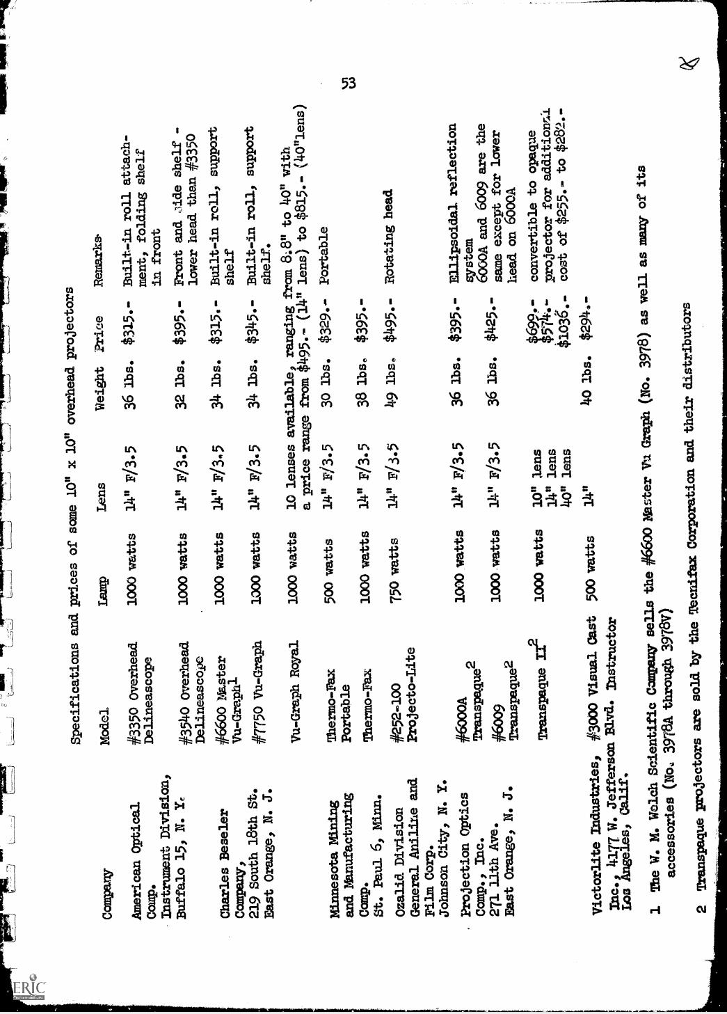
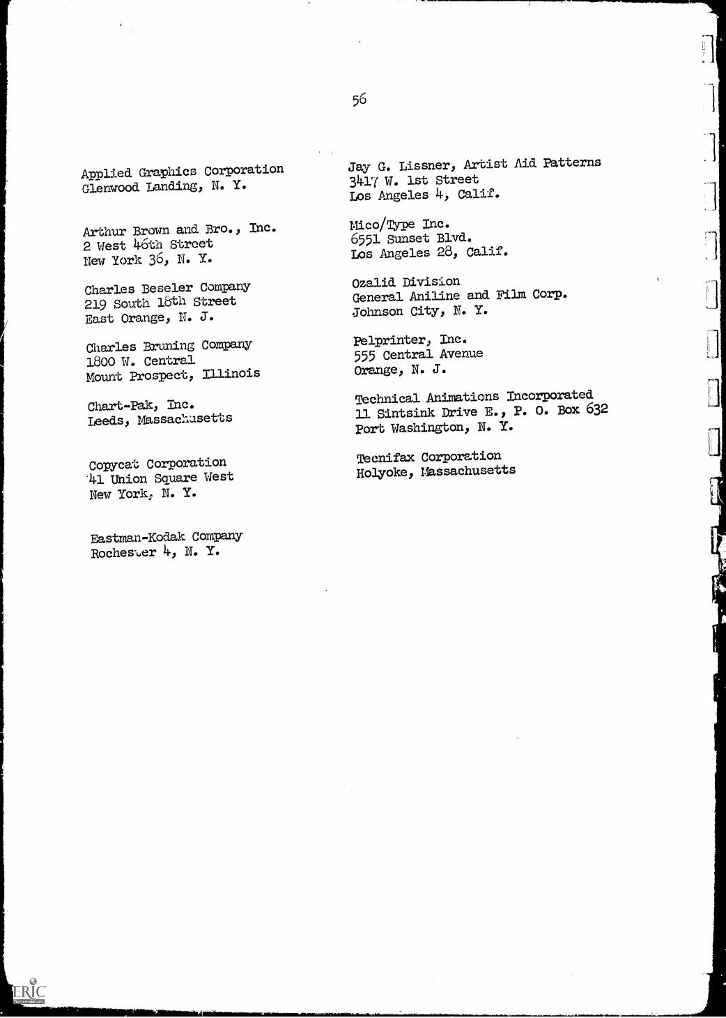
IX B - SOURCES CF EQUIPMENT AND MATERIALS 52
1. Purchasing an overhead projector 52
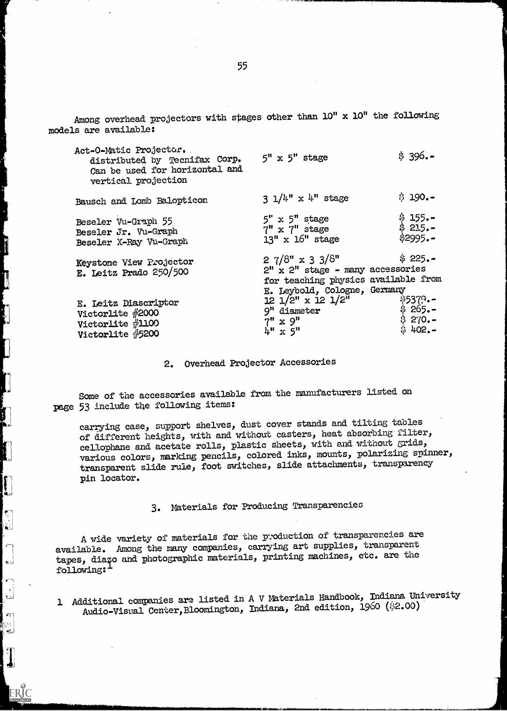
2. Overhead projector accessories 553. Material for producing transparencies 55
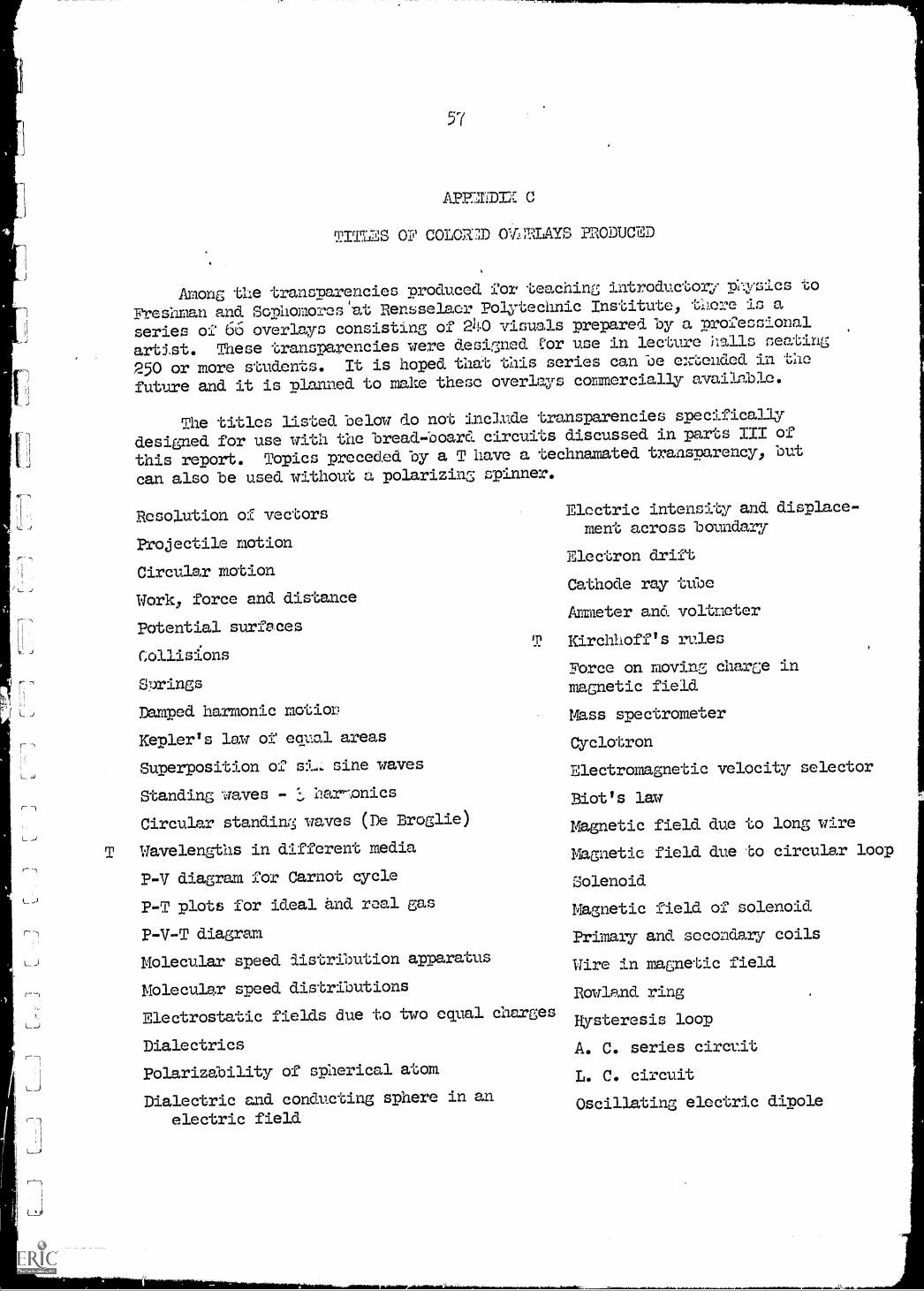
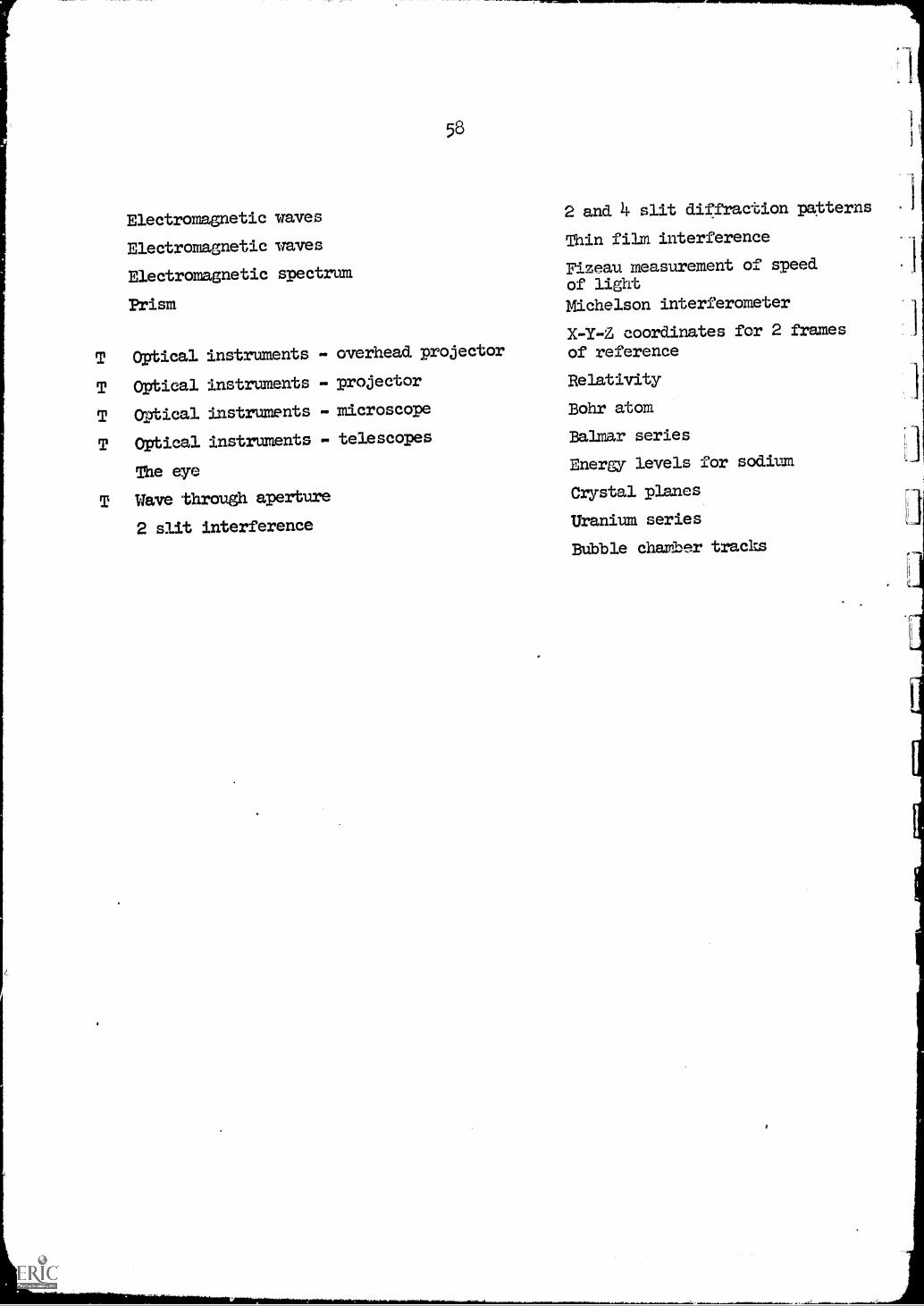
APPENDIX C - EXILES OF COLORED OVERLAYS PRODUCED AT R. P. I. 57
1
INTRODUCTION
recent years the overhead projector has found its way into schools
and colleges. Its many advantages over conventional black boards are
discussed by the leading manufacturers in their literature and examples
are given in numerous publications some of which are listed in appendix A4
In this report we shall assume that an instructor has an overhead projector
at his disposal and is familiar with the operation of this device and its
accessories. Information on projection distances, image size and the posi-
tioning of the screen to minimize the keystone effect is usually given by
the manufacturer.
In our use of overhead projectors, we have restricted ourselves to the
10" by 10" stage which seems to be common to most projectors put on the
market in recent years. The projection lamps used nowadays are usually of
the 1000 watt type, although a few older models use 500 watt lamps. A few
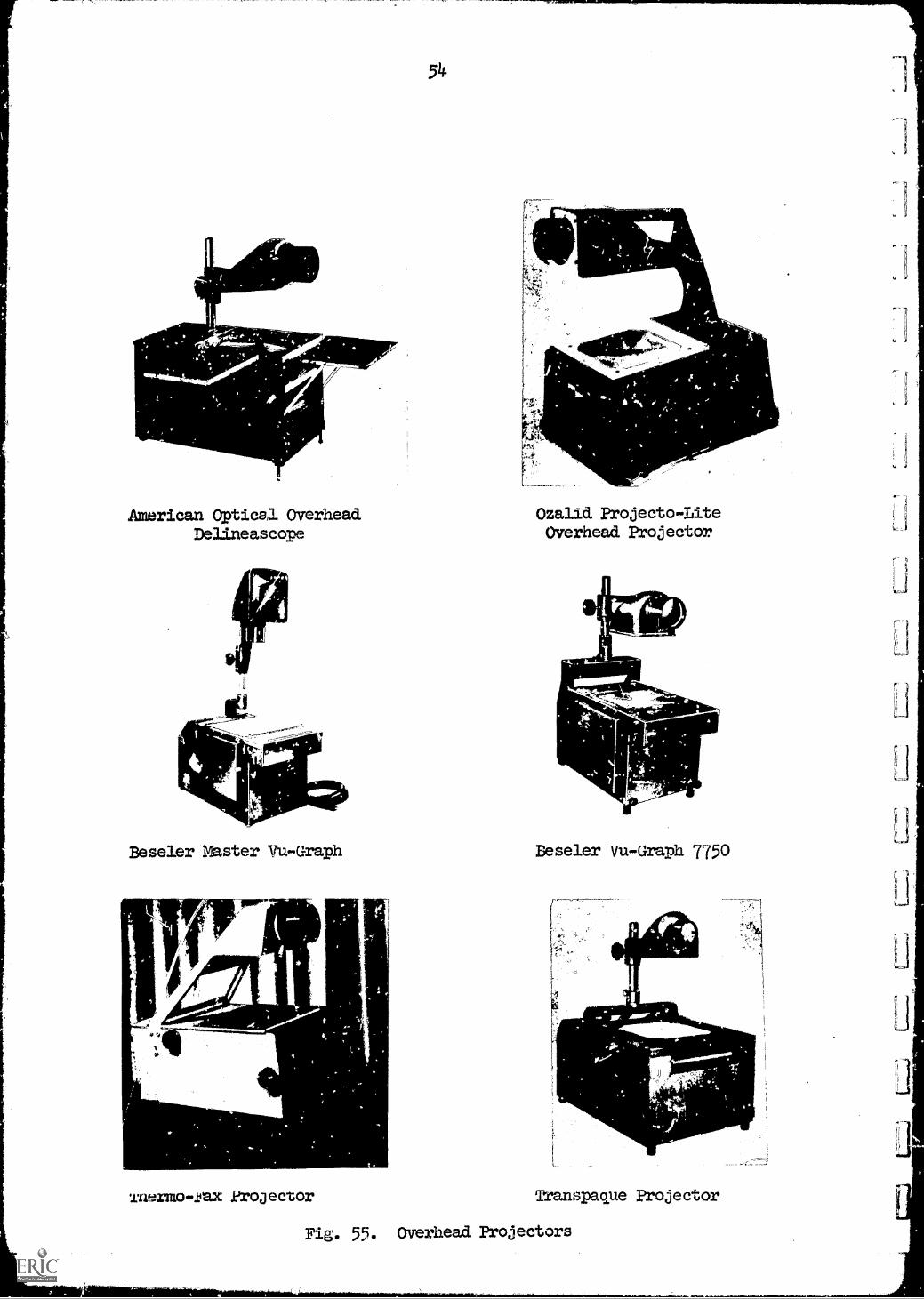
typical projectors currently available are shown in appendix B, together
with their specifications and present costs.
It is not the purpose of this report to give a complete summary of
applications of the overhead projector in the physics lecture, but to give
examples of some of the specific ways in which it can be used. It is then
left up to the ingenuity of the lecturer to invent his own accessories
designed to fit his particular needs. These needs depend on many factors,
such as the level of the course, the course material covered, the number of
students, the size of the lecture room and the availability of materials as
well as of shop facilities. It is hoped that the examples chosen willstimulate the physics lecturer sufficiently so that he will add his own
ideas to those presented.
All accessories described have been designed specifically for the
physics lectures presented to the Freshman and Sophomores at Rensselaer
Polytechnic Institute. Our lecture hall holds 320 students and has, on
occasions, been completely filled. In general we lecture to 260 to 300
students. Although the lecture hall has been designed many years ago, it
is well suited for overhead projection because of the considerable distance
from the first raw to the demonstration table. The front screen is
sufficiently high to avoid any interference from the projector, the lecturer
or the demonstration equipment. Large demonstration pieces on the lecture
table make the use of the overhead projector almost mandatory, because the
blackboard is easily obscured. The spot and blackboard lights are usuallyturned off when the projector is in use; they are turned on for other
demonstrations. The level of illumination in our lecture hall is continu-ously variable and is - for best visibility - set somewhat below the maximum
level. Every effort is made to have as much light as possible at all seats
and still get a clear image on the screen.
At this time it may be pointed out that the use of the overhead projector
2
teaching sections of twenty students because of the possibilities of
preparing materials ahead of time and demonstrating phenomena difficult to
show by any other means.
For the purpose of this report, the accessories devised for use with
the overhead projector in physics lectures have been divided into four
groups: Transparencies, models and demonstrations, breadboard for electrical
experiments and the plotter. Each of these will be discussed semrately.
3
PART I
PRODUCTION AND USE OF TRANSPARENCIES
1. Replacing the Blackboard
The usefulness of the overheau projector in replacing the blackboard is
generally discussed by the manufacturers and will not be dealt with at great
length in this report. The lecturer faces his class, he is able to watch
the students and thereby judge their reaction to his presentation, he stays
at the same place throughout his lecture, and he does not have to erase part
of his lecture. In a demonstration lecture there is also the possibilitr
that large pieces of equipment on the lecture table may obscure the black-
board, at least for some students. A screen at the center of the room is
high enough to give a clear view to everyone in the lecture hall.
The main advantage in lecturing by use of the overhead projector is,
of course, the possibility of preparing material ahead of time. This
preparation may be done by the lecturer just prior to his lecture, the night
before, or by an artist in a professional studio, depending on the time and
funds available.
Once a transparency has been prepared, it is stored for future use and
is always available. When a file of overlays has been built up, the task of
preparing and giving a lecture will be very much simplified. Besides their
use for regular classes, such a collection of transparencies has proved very
helpful when preparing programs for various groups.
2. Design of Transparencies
An overhead transparency consists of a number of visual elements which
have been carefully related to one another so as to form a unified composite
visualization of an idea, event, object, and the like.
Transparencies which communicate effectively result from the knowledgeable
application of the principles and elements of design.
The principles of repetition, balance, emphasis, unity, and contrast in
design are the guides employed by the artist when creating a plan for
arranging the various parts of the transparency.
Space, line, color, size, shape, and texture are the tools with which
the artist works to make the design of the transparency as effective as
possible.
Good design is a significant factor in determining the communicative
power of any overheaa transparency. It is important that the content authority,
as well as the artist who prepares the artwork, develop an understanding and
an appreciation for the role played by these design characteristics in the
weparatiOn of effective instructional materials.
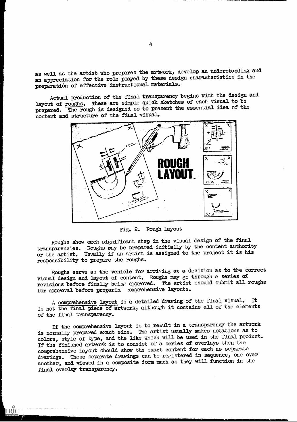
Actual production of the final transparency begins with the design and
layout of roughs. These are simple quick sketches of each visual to be
prepared. The rough is designed so to present the essential idea of the
content and structure of the final visual.
ROUGHLAYOUT
X X
C7C04VO4
Fig. 2. Rough layout
Roughs show each significant step in the visual design of the final
transparencies. Roughs may be prepared initially by the content authority
or the artist. Usually if an artist is assigned to the project it is his
responsibility to prepare the roughs.
Roughs serve as the vehicle for arriving at a decision as to the correct
visual design and layout of content. Roughs may go through a series of
revisions before finally being approved. The artist should submit all roughs
for approval before preparin, :omprehensive layouts.
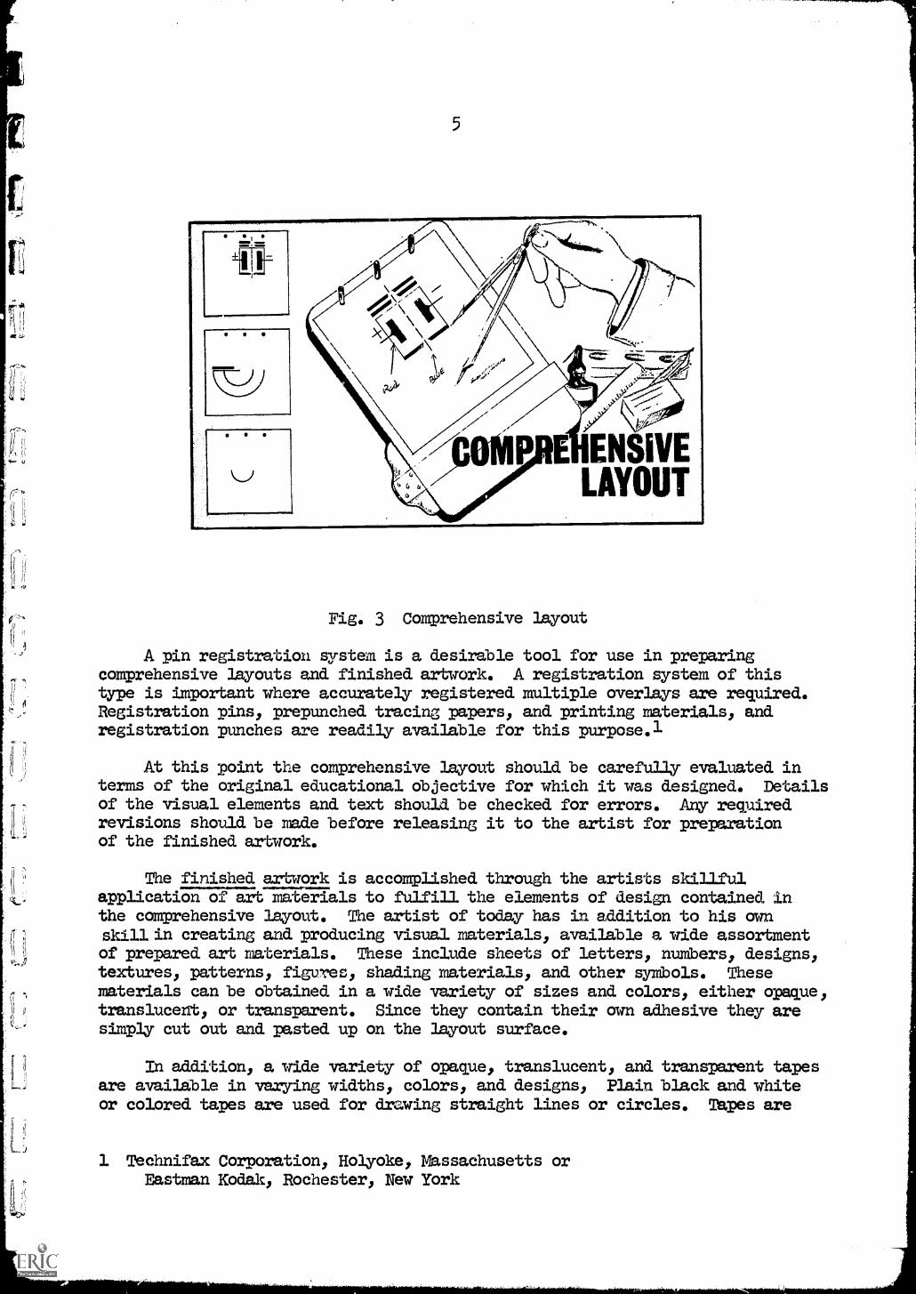
A comprehensive layout is a detailed drawing of the final visual. It
is not the final Piece of artwork, although it contains all of the elements
of the final transparency.
If the comprehensive layout is to result in a transparency the artwork
is normally prepared exact size. The artist usually makes notations as to
colors, style of type, and the like which will be used in the final product.
If the finished artwork is to consist of a series of overlays then the
comprehensive layout should show the exact content for each as separate
drawings. These separate drawings can be registered in sequence, one over
another, and viewed in a composite form much as they will function in the
final overlay transparency.
5
Fig. 3 Comprehensive layout
A pin registration system is a desirable tool for use in preparingcomprehensive layouts and finished artwork. A registration system of thistype is important where accurately registered multiple overlays are required.Registration pins, prepunched tracing papers, and printing materials, andregistration punches are readily available for this purpose.l
At this point the comprehensive layout should be carefully evaluated interms of the original educational objective for which it was designed. Detailsof the visual elements and text should be checked for errors. Any requiredrevisions should be made before releasing it to the artist for preparationof the finished artwork.
The finished artwork is accomplished through the artists skillfulapplication of art materials to fulfill the elements of design contained inthe comprehensive layout. The artist of today has in addition to his ownskill in creating and producing visual materials, available a wide assortmentof prepared art materials. These include sheets of letters, numbers, designs,textures, patterns, figures, shading materials, and other symbols. Thesematerials can be obtained in a wide variety of sizes and colors, either opaque,translucent, or transparent. Since they contain their own adhesive they aresimply cut out and pasted up on the layout surface.
In addition, a wide variety of opaque, translucent, and transparent tapesare available in varying widths, colors, and designs, Plain black and whiteor colored tapes are used for drawing straight lines or circles. Tapes are
1 Technifax Corporation, Holyoke, Massachusetts orEastman Kodak, Rochester, New York
6
also available which contain numbers, letters, symbols and the like.
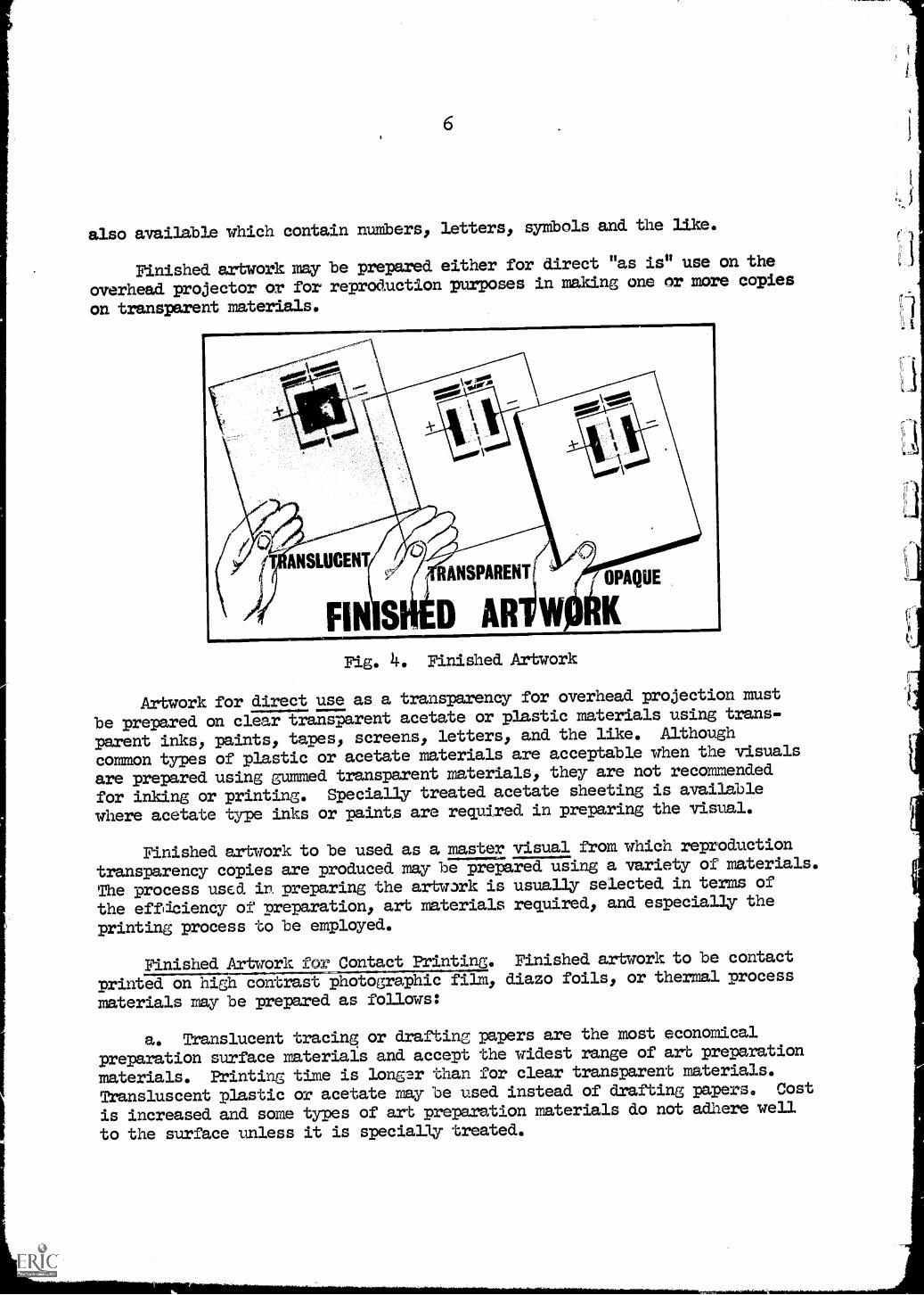
Finished artwork may be prepared either for direct "as is" use on the
overhead projector or for reproduction purposes in making one or more copies
on transparent materials.
Fig. 4. Finished Artwork
Artwork for direct use as a transparency for overhead projection must
be prepared on clear transparent acetate or plastic materials using trans-
parent inks, paints, tapes, screens, letters, and the like. Although
common types of plastic or acetate materials are acceptable when the visuals
are prepared using gummed transparent materials, they are not recommended
for inking or printing. Specially treated acetate sheeting is available
where acetate type inks or paints are required in preparing the visual.
Finished artwork to be used as a master visual from which reproduction
transparency copies are produced may be prepared using a variety of materials.
The process used in preparing the artwork is usually selected in terms of
the effdciency of preparation, art materials required, and especially the
printing process to be employed.
Finished Artwork for Contact Printing. Finished artwork to be contact
printed on high contrast photographic filmy diazo foils, or thermal process
materials may be prepared as follows:
a. Translucent tracing or drafting papers are the most economical
preparation surface materials and accept the widest range of art preparation
materials. Printing time is longer than for clear transparent materials.
Transluscent plastic or acetate may be used instead of drafting papers. Cost
is increased and some types of art preparation materials do not adhere well
to the surface unless it is specially treated.
7
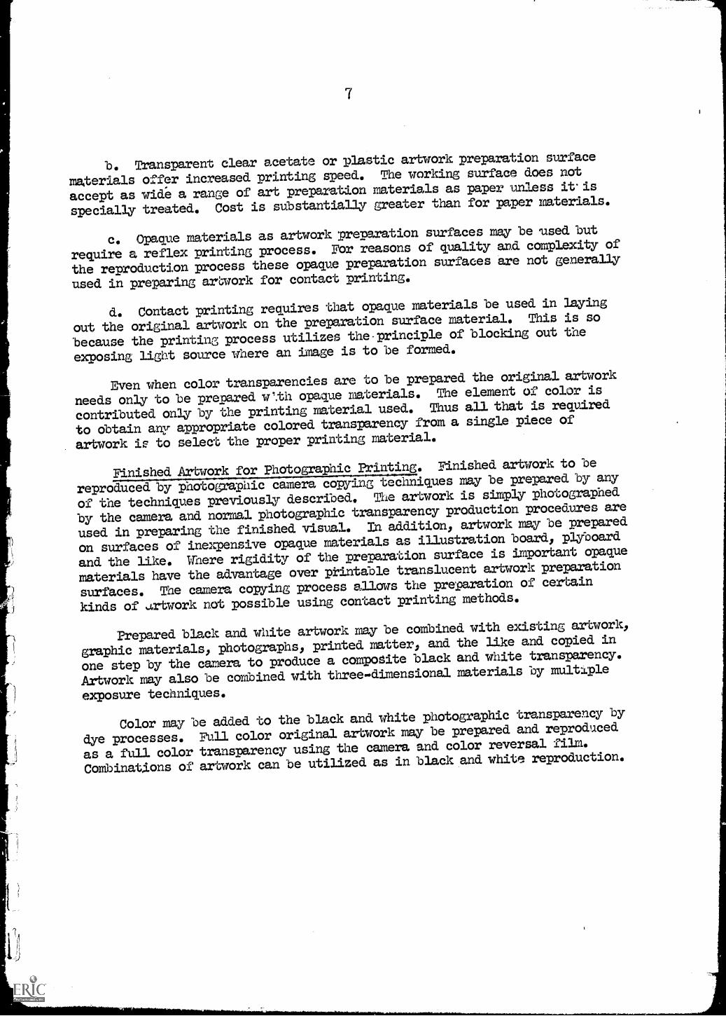
b. Transparent clear acetate or plastic artwork preparation surface
materials offer increased printing speed. The working surface does not
accept as wide a range of art preparation materials as paper unless itis
specially. treated. Cost is substantially greater than for paper materials.
c. Opaque materials as artwork preparation surfaces may be used but
require a reflex printing process. For reasons of quality and complexity of
the reproduction process these opaque preparation surfaces are not generally
used in preparing artwork for contact printing.
d. Contact printing requires that opaque materials be used in laying
out the original artwork on the preparation surface material. This is so
because the printing process utilizes the principle of blocking out the
exposing light source where an image is to be formed.
Even when color transparencies are to be prepared the original artwork
needs only to be prepared w%th opaque materials. The element of color is
contributed only by the printing material used. Thus all that is required
to obtain any appropriate colored transparency from a single piece of
artwork ie to select the proper printing material.
Finished Artwork for Photographic Printing. Finished artwork to be
reproduced by photographic camera copying techniques may be prepared by any
of the techniques previously described, The artwork is simply photographed
by the camera and normal photographic transparency production procedures are
used in preparing the finished visual. In addition, artwork may be prepared
on surfaces of inexpensive opaque materials as illustration board, plyboard
and the like, Where rigidity of the preparation surface is important opaque
materials have the advantage over printable translucent artwork preparation
surfaces, The camera copying process allows the preparation of certain
kinds of artwork not possible using contact printing methods.
Prepared black and white artwork may be combined with existing artwork,
graphic materials, photographs, printed matter, and the like and copied in
one step by the camera to produce a composite black and white transparency.
Artwork may also be coMbined with three-dimensional materials by multiple
exposure techniques.
Color may be added to the black and white photographic transparency by
dye processes. Full color original artwork may be prepared and reproduced
as a full color transparency using the camera and color reversal film.
Combinations of artwork can be utilized as in black and white reproduction.
8
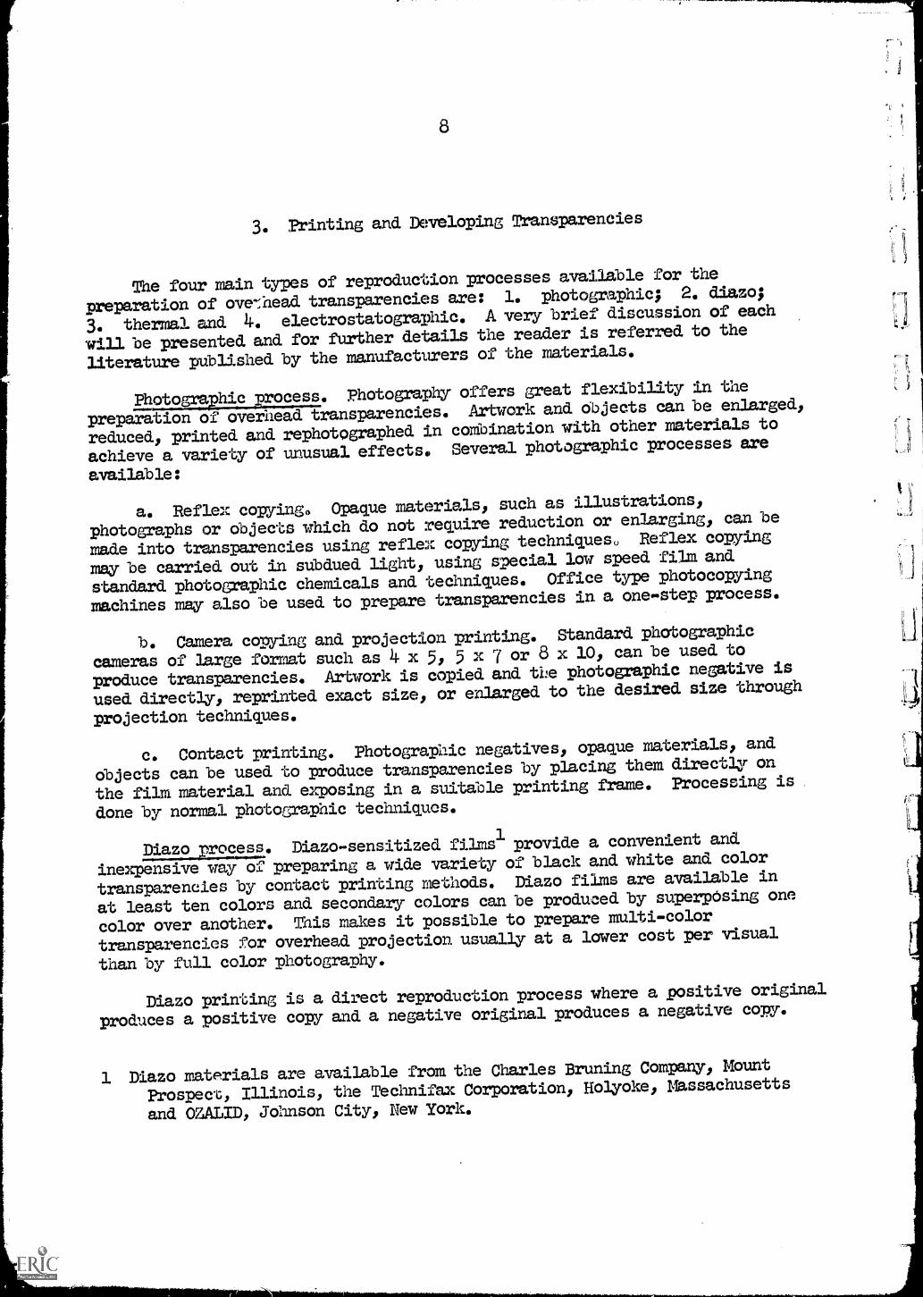
3. Printing and Developing Transparencies
The four main types of reproduction processes available for the
preparation of overhead transparencies are: 1. photographic; 2. diazo;
3. thermal and 4. electrostatographic. A very brief discussion of each
will be presented and for further details the reader is referred to the
literature published by the manufacturers of the materials.
Photographic process. Photography offers great flexibility in the
preparation of overhead transparencies. Artwork and objects can be enlarged,
reduced, printed and rephotographed in combination with other materials to
achieve a variety of unusual effects* Several photographic processes are
available:
a. Reflex copying, Opaque materials, such as illustrations,
photographs or objects which do not require reduction or enlarging, can be
made into transparencies using reflex copying techniques. Reflex copying
may be carried out in subdued light, using special low speed film and
standard photographic chemicals and techniques. Office type photocopying
machines may also be used to prepare transparencies in a one-step process.
b. Camera copying and projection printing. Standard photographic
cameras of large format such as 4 x 5, 5 x 7 or 8 x 10, can be used to
produce transparencies. Artwork is copied and the photographic negative is
used directly, reprinted exact size, or enlarged to the desired size through
projection techniques.
c. Contact printing. Photographic negatives, opaque materials, and
objects can be used to produce transparencies by placing them directly on
the film material and exposing in a suitable printing frame. Processing is
done by normal photographic techniques.
ElmoEmma. Diazo-sensitized films1 provide a convenient and
inexpensive way of preparing a wide variety of black and white and color
transparencies by contact printing methods. Diazo films are available in
at least ten colors and secondary colors can be produced by superposing one
color over another. This makes it possible to prepare multi-color
transparencies for overhead projection usually at a lower cost per visual
than by full color photography.
Diazo printing is a direct reproduction process where a positive original
produces a positive copy and a negative original produces a negative copy.
1 Diazo materials are available from the Charles Bruning Company, Mount
Prospect, Illinois, the Technifax Corporation, Holyoke, Massachusetts
and =LID, Johnson City, New York.
9
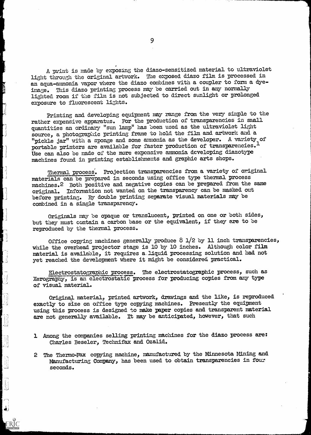
A print is made by exposing the diazo-sensitized material to ultraviolet
light through the original artwork. The exposed diazo film is processed in
an aqua-ammonia vapor where the diazo combines with a coupler to form a dye-
image. This diazo printing process may be carried out in any normally
lighted room if the film is not subjected to direct sunlight or prolonged
exposure to fluorescent lights.
Printing and developing equipment may range from the very simple to the
rather expensive apparatus. For the production of transparencies in small
quantities an ordinary "sun lamp" has been used as the ultraviolet light
source, a photographic printing frame to hold the film and artwork and a
"pickle jar" with a sponge and some ammonia as the developer. A variety of
portable printers are available for faster production of transparencies.1
Use can also be made of the more expensive ammonia developing diazotype
machines found in printing establishments and graphic arts shops.
Thermal process. Projection transparencies from a variety of original
materials can be prepared in seconds using office type thermal process
machines.2 Both positive and negative copies can be prepared from the same
original. Information not wanted on the transparency can be masked out
before printing. By double printing separate visual materials may be
combined in a single transparency.
Originals may be opaque or translucent, printed on one or both sides,
but they must contain a carbon base or the equivalent, if they are to be
reproduced by the thermal process.
Office copying machines generally produce 8 1/2 by 11 inch transparencies,while the overhead projector stage is 10 by 10 inches. Although color filmmaterial is available, it requires a liquid processing solution and had not
yet reached the development where it might be considered practical.
Electrostatographic process. The electrostatographic process, such asXerography, is an electrostatic process for producing copies from any type
of visual material.
Original material, printed artwork, drawings and the like, is reproduced
exactly to size on office type copying machines. Presently the equipment
using this process is designed to make paper copies and transparent material
are not generally available. It may be anticipated, however, that such
1 Among the companies selling printing machines for the diazo process are:Charles Beseler, Technifax and OzaLid.
2 The Thermo-rax copying machine, manufactured by the Minnesota Mining andManufacturing Company, has been used to obtain transparencies in four
seconds.
10
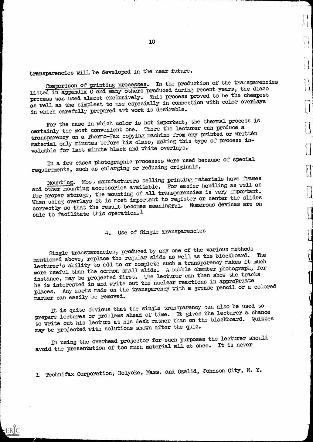
transparencies will be developed in the near future.
Comparison of printing processes. In the production of the transparencies
listed in appendix C and many others produced during recent years, the diazo
process was used almost exclusively. This process proved to be the cheapest
as well as the simplest to use especially in connection with color overlays
in which carefully prepared art work is desirable.
For the case in which color is not important, the thermal process is
certainly the most convenient one. There the lecturer can produce a
transparency on a Thermo-Fax copying machine from any printed or written
material only minutes before his class, making this type of process in-
valuable for last minute black and white overlays.
In a few cases photographic processes were used because of special
requirements, such as enlarging or reducing originals.
Mounting. Most manufacturers selling printing materials have frames
and other mounting accessories available. For easier handling as well as
for proper storage, the mounting of all transparencies is very important.
When using overlays it is most important to register or center the slides
correctly so that the result becomes meaningful. Numerous devices are on
sale to facilitate this operation.1
4. Use of Single Transparencies
Single transparencies, produced by any one of the various methods
mentioned above, replace the regular slide as well as the blackboard. The
lecturer's ability to add to or complete such a transparency makes it much
more useful than the common small slide. A bubble chamber photograph, for
instance, may be projected first. The lecturer can then show the tracks
he is interested in and write out the nuclear reactions in approPriate
places. Any marks made on the transparency with a grease pencil or a colored
marker can easily be removed.
It is quite obvious that the single transparency can also be used, to
prepare lectures or problems ahead of time. It gives the lecturer a chance
to write out his lecture at his desk rather than on the blackboard. Quizzes
may be projected with solutions shown after the quiz.
In using the overhead projector for such purposes the lecturer should
avoid the presentation of too much material all at once. It is never
1 Technifax Corporation, Holyoke, Mass. and Ozalid, Johnson City, N. Y.
desirable to have a lengthy derivation or a complicated problem suddenly
appear on the screen. This does not always give the student a chance to
follow the exposition in an orderly manner, nor is he able to take notes.
It is better to cover such a transparency with a sheet of paper which is
removed slowly, line by line, at a pace not too fast for students to follow.
It is very important to pay close attention to the size of the writing
on the transparencies, as well as the space left for figures. How large
a symbol to use in order to be clearly readable from the last row of the
lecture hall depends, of course, on the size of the classroom, as well as
on the size of the image or screen. Every lecturer must try various letter
and figure sizes in each room before making any transparencies. It was
found, for instance, that typed materials were not suitable even for medium
sized rooms. Besides the size of lei,ters and figures, the line width and
the color used are important factors in assuring maximum visibility.
A set of coordinate system transparencies is commercially available)
and may prove useful in physics lectures. The set of five single 10" x 10"
slides includes rectangular, polar, 2-cycle semilogarithmic, 2 x 2 cycle
logarithmic and 3 dimensional rectangular coordinates.
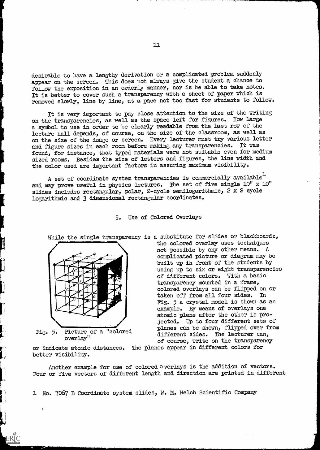
5. Use of Colored Overlays
While the single transparency is a substitute for slides or blackboards,the colored overlay uses techniquesnot possible by any other means. Acomplicated picture or diagram may bebuilt up in front of the students byusing up to six or eight transparenciesof different colors. With a basictransparency mounted in a frame,colored overlays can be flipped on ortaken off from all four sides. In
Fig. 5 a crystal model is shown as anexample. By means of overlays oneatomic plane after the other is pro-
\ jected. Up to four different sets ofplanes can be shown, flipped over fromdifferent sides. The lecturer can,of course, write on the transparency
or indicate atomic distances. The planes appear in different colors for
better visibility.
Fig. 5. Picture of a "coloredoverlay"
Another example for use of colored overlays is the addition of vectors.Four or five vectors of different length and direction are printed in different
1 No. 7067 B Coordinate system slides, W. M. Welch Scientific Company
12
colors, one per sheet. They are superimposed, adding them by the polygon
method. The resultant is then shown to complete the polygon. In this
example the sheets are not mounted, so that the vectors can be added in
different orders, demonstrating the fact that the resultant is always the
same and independent of the order in which the vectors are added.
A series of colored overlays for use in introductory physics has been
produced and a list of titles is given in Appendix C. This list, at the
present time, does not represent a complete course in physics, but gives
examples of the types of overlays found useful in teaching large groups of
freshmen and sophomores. The overlays can be produced by any one of the
methods described previously; most titles mentioned in the appendix were
made on diazochrome color film. Some of these colors project much betterthan others, and it is important to choose the proper order of colors.
important parts of the figure to be projected should be in dark colors,
e.g. red, blue and black, while incidentals, such as coordinate systems
can be in light colors.
With each overlay some lighT, is absorbed, of course. For this reason
it is not advisable to exceed 6-3 overlays because the image will lose some
of its brightness.
6. Movable Transparencies
Another advantage of the overhead projector is the possibility of
moving transparencies through small distances. For example, two coordinate
systems can be moved with respect to each other when starting a discussion
of the special theory of relativity. Special tracks are commercially
available for mounting movable transparencies.
Cut-out sections can be moved from the side by clear plastic handles.
A grommet machine is useful when it is desired to have elements of a
transparency move in a circle.
7. Technamated Transparencies
In many cases a principle can be taught more effectively if continuous
motion is involved, such as a wave moving across a boundary and changing
its velocity and wave length. In such cases, "technamated" slides are
employed.
The process of technamation uses the principle of rotary polarization.
Special materials, consisting of thin birefringent, polarized plasticsarranged and permanently mounted on acetate sheets, are available to make up
13
definite motion patterns.1 The motion is actuated by placing a rotating
polarizing disk between the light path passing through the transparency
and the screen. For most overhead projectors a polarizing spinner can be
mounted on the projector lens.2 Fig. 1 shows a Beseler variable speed
motor spinner on a Beseler projector.
Tbchnamated slides or overlays are prepared by using the special
materials for the construction of polarized animated transparencies. A
variety of materials are available for a matitude of effects at different
speeds including a reversal of motion.
Technamated transparencies included in the list of colored overlays
in appendix C are marked with a T.
1 Technamation materials and kits are available from:
American Optical Company, Instrument Division, Buffalo 15, N. Y.
Technical Animations Incorporated, 11 Sintsink Drive E, P. 0.
Box 632, Port Washington, N. Y.
Technifax Corporation, Holyoke, Mass.
2 Polarizing spinner with variable speed motor, Charles Beseler Co.
219 South 18th Street, East Orange, N. J.
Polarizing Disc, American Optical Company, Instrument Division, Buffalo 15, N. f.
Motorized Analyzers for Transpaque and Beseler Projectors, Technifax
Corporation, Holyoke, Mai.
1k
PART II
THE OVERHEAD PROJECTOR IN la DEMONSTRATION LECTURE
1. Visual Aid Versus Lecture Demonstration
The use of a projector for lecture demonstrations is not new. Various
still and movable models, projection meters, etc. for 3 1/4 x 4" slide
projectors have been in use for decades. The projection of actual demon-
strations in chemistry, using a slide projector, was described in the
literature over twenty years ago.1 At that time, however, slide projectors
with a small stage had to be used. With the development of the 10" x 10"
stage and an- .efficient optical system on modern overhead projectors,
experiments can be carried out with greater ease and better visibility.
Any physicist using an, overhead projector will soon find it a useful
projection technique in a variety of situations. Old demonstration
experiments, formerly made visible by means of carbon arcs or other shadow
projection apparatus, can now be projected with .put any special set-ups or
adjustments by making use of the stage of an overhead projector.
The physics lecturer should differentiate between the use of an overhead
projector as a visual aid and its use for the demonstration of physical
phenomena or actual experiments. Both of these methods are discussed in
the following pages and in many cases their combined application is stressed.
When technamation is used in a discussion of wave motion, by making use of
birefringent materials and a rotating polaroid, students see a moving wave.
This is, however, a pure visual aid and not a demonstration of the behavior
of waves. On the other hand, the same use of technamated transparancies
becomes a demonstration of physical phenomena when used in discussing the
principles of polarization.
Using the projector to shadow - project the components of an electric
circuit is a visual aid; when the `,eh is closed, however, and a real
measurement is taken, the visual aid has turned into an actual experiment
of a qualitative or quantitative nature. The overhead projector, although
originally designed purely as a visual aid, can easily be used to make real
physical demOnstrations and experiments visible to large groups of students.
It is certainly not proposed that all lecture demonstrations be
performed on the 10 inch by 10 inch stage of an overhead projector. Students
should watch the lecturer actually perform numerous experiments using equipr
ment sufficiently large and loud to be seen or heard by everyone in the room.
Other types of visual aids such as closed circuit TV, shadow projection,
1 A. J. Chem. Ed., 16, 314 (1939) and 17, 210 (1940)
15
films, slides, stroboscopic illumination and large models have their place
in any physics lecture. It was found, however, that the visibility of many
old demonstrations could be improved considerably by the use of overhead
projection.
Demonstrations can be performed in a vertical plane, by mounting the
projector on its side and using'a mirror to reflect the light upward through
the projector lens mounted on a vertical shaft. A 5" x 5" overhead
projector for both, horizontal and vertical projection, is now on the market.2
One definite advantage of working with the overhead projector is the
ease of storing its rather sma7.1 accessories. It should be pointed out,
however, that any equipment to be used for projection purposes must be
stored in a dustfree place, preferably covered with a plastic bag or put
into a closed cabinet.
It is believed that the overhead projector can become an extremely
useful tool in the production of films and in the use of television.
Methods described in this report are adoptable for use by a lecturer in
front of a camera - movie or T. V. The use of the overhead projector is
already widespread in commercial television studios and will grow with the
further increase of closed circuit television in educational fields.
2. Motorizing the Projector
Two motors were attached to the overhead projector as shown in Fig. 1.
The rear motor with a gear reduction has a constant speed of about 7
revolutions per minute. It is coupled to the axle driving the cellophane
or acetone roll on the projector and thereby enables the lecturer to have
the roll move across the projector at a constant speed.
The second motor is mounted on the same side of the projector but on a
slotted aluminum angle. This allows the lecturer to move the motor to any
desired position. The speed of this motor can be varied from about 10 to
35 revolutions per minute by means of a rheostat. It is used to drive
accessories mounted on the stage of the projector.
Some examples of the use of these motors are given below:
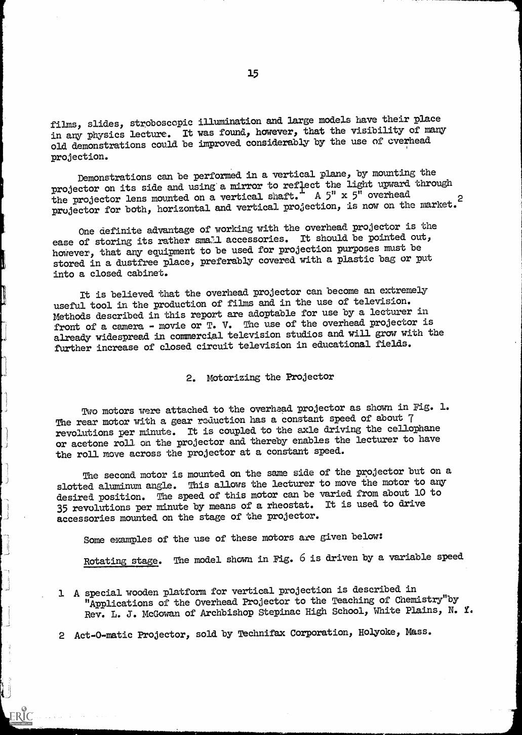
Rotating stage. The model shown in Fig. 6 is driven by a variable speed
.1 A special wooden platform for vertical projection is described in
"Applications of the Overhead Projector to the Teaching of Chemistry"by
Rev. L. 3. McGowan of Archbishop Stepinac High School, White Plains, N. Y.
2 Act-O-matic Projector, sold. by Technifax Corporation, Holyoke, Mass.
motor mounted on the projector. The rotating plastic disk may be used when
discussing circular motion, rotating vectors, circular orbits of satellites
or electrons in the Bohr model.
t
Fig. 6. Rotating stage
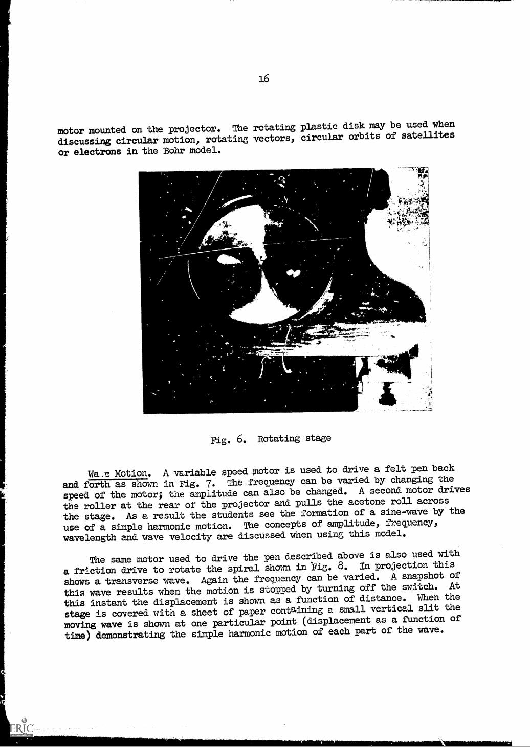
Wa.e Motion. A variable speed motor is used to drive a felt pen back
and forth as shown in Fig. 7. The frequency can be varied by changing the
speed of the motor; the amplitude can also be changed. A second motor drives
the roller at the rear of the projector and pulls the acetone roll across
the stage. As a result the students see the formation of a sine-wave by the
use of a simple harmonic motion. The concepts of amplitude, frequency,
wavelength and wave velocity are discussed when using this model.
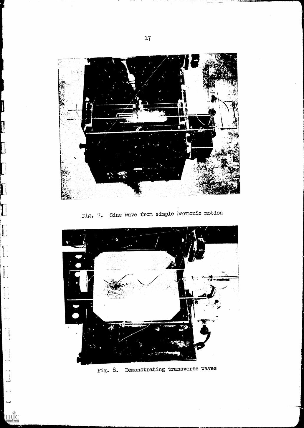
The same motor used to drive the pen described above is also used with
a friction drive to rotate the spiral shown in Fig. 8. In projection this
shows a transverse wave. Again the frequency can be varied. A snapshot of
this wave results when the motion is stopped by turning off the switch. At
this instant the displacement is shown as a function of distance. When the
stage is covered with a sheet of paper containing a small vertical slit the
moving wave is shown at one particular point (displacement as a function of
time) demonstrating the simple harmonic motion of each part of the wave.
17
Fig. 7. Sine wave From simple harmonic motion
f "Noriemitir-1
- 0
Fig. 8. Demonstrating transverse waves
18
3. Tracks Left by Rolling Balls
\.
001
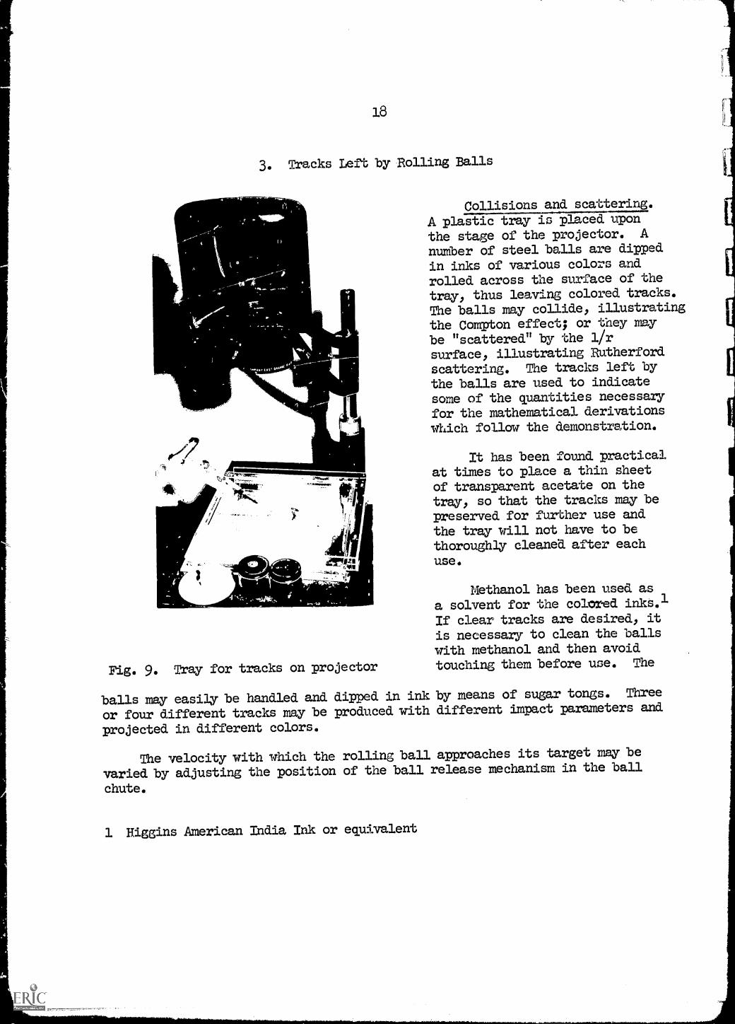
Fig. 9. Tray for tracks on projector
Collisions and scattering.
A plastic tray is placed upon
the stage of the projector. Anumber of steel balls are dipped
in inks of various colors and
rolled across the surface of the
tray, thus leaving colored tracks.
The balls may collide, illustratingthe Compton effect; or they maybe "scattered" by the 1/r
surface, illustrating Rutherford
scattering. The tracks left bythe balls are used to indicatesome of the quantities necessaryfor the mathematical derivations
which follow the demonstration.
It has been found practicalat times to place a thin sheetof transparent acetate on thetray, so that the tracks may bepreserved for further use andthe tray will not have to bethoroughly cleaned after eachuse.
Methanol has been used as
a solvent for the colored inks.1
If clear tracks are desired, it
is necessary to clean the ballswith methanol and then avoidtouching them before use. The
balls may easily be handled and dipped in ink by means of sugar tongs. Three
or four different tracks may be produced with different impact parameters and
projected in different colors.
The velocity with which the rolling ball approaches its target may be
varied by adjusting the position of the ball release mechanism in the ball
chute.
1 Higgins American India Ink or equivalent
0
19
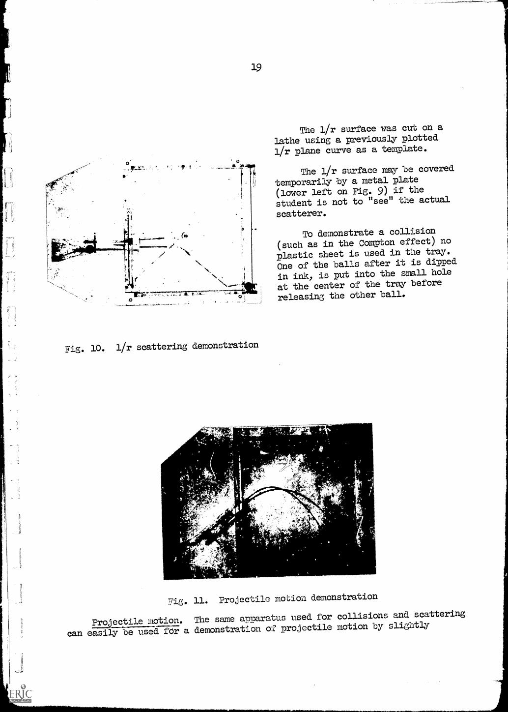
Fig. 10. 1/r scattering demonstration
1.4 ,AhLC. i
The 1/r surface was cut on a
lathe using a previously plotted
1/r plane curve as a template.
The l/r surface may be covered
temporarily by a metal plate
(lower left on Fig. 9) if the
student is not to "see" the actual
scatterer.
To demonstrate a collision
(such as in the Compton effect) no
plastic sheet is used in the tray.
One of the balls after it is dipped
in ink, is put into the small hole
at the center of the tray before
releasing the other ball.
rt
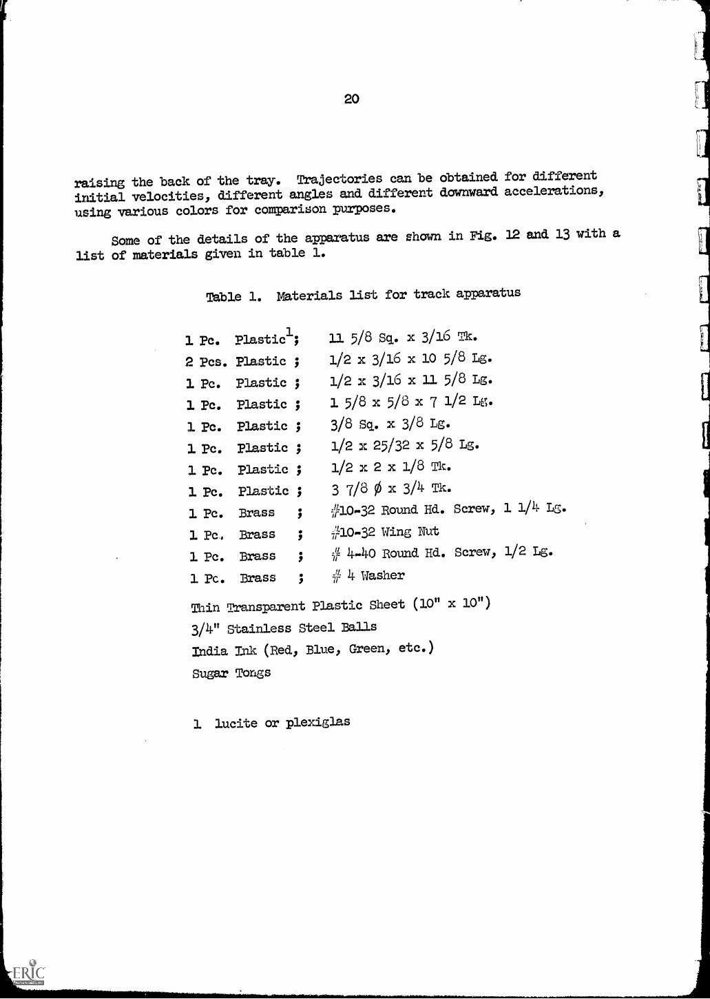
Fig. 11. Projectile motion demonstration
Projectile motion. The same apparatus used for collisions and scattering
can easily be used for a demonstration of projectile motion by slightly
20
raising the back of the tray. Trajectories can be obtained for different
initial velocities, different angles and different downward accelerations,
using various colors for comparison purposes.
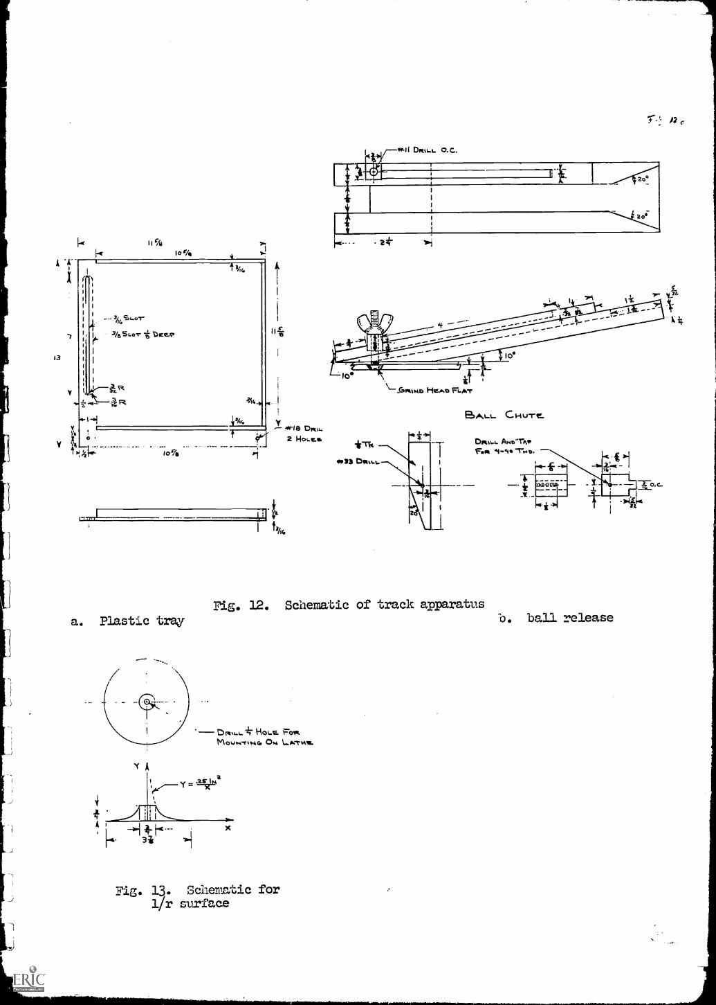
Some of the details of the apparatus are shown in Fig. 12 and 13 with a
list of materials given in table 1.
Table 1. Materials list for track apparatus
1 Pc. Plastici; 11 5/8 Sq. x 3/16 Tk.
2 Pcs. Plastic ; 1/2 x 3/16 x 10 5/8 Lg.
1 Pc. Plastic ; 1/2 x 3/16 x 11 5/8 Lg.
1 Pc. Plastic ; 1 5/8 x 5/8 x 7 1/2 Lg.
1 Pc. Plastic ; 3/8 Sq. x 3/8 Lg.
1 Pc. Plastic ; 1/2 x 25/32 x 5/8 Lg.
1 Pc. Plastic ; 1/2 x 2 x 1/8 Tk.
1 Pc. Plastic ; 3 7/8 0 x 3/4 Tk.
1 Pc. Brass ://10-32 Round Hd. Screw, 1 1/4 Ls.
1 Pc, Brass 7.110-32 Wing Nut
1 Pc. Brass :/114.40 Round Hd. Screw, 1/2 Lg.
1 Pc. Brass ; r-1 4 Washer
Thin Transparent Plastic Sheet (10" x 10")
3/4" Stainless Steel Balls
India Ink (Red, Blue, Green, etc.)
Sugar Tongs
1 lucite or plexiglas
A
k 11%tor/4
r
3/1
10%
a. Plastic tray
`f A
44
I Si
4IE3 DpetL.
2 HO L. CS
,A.1 DR$L.L. O.C.
2 O
2o;
' A?
HZAT1 FLAT
BALL Ct-tu-re.
DPI161 Amer',"FoIVI 41.
Fig. 12. Schematic of track apparatus
(DRILL..4 HOLE. F0.1.MOLWett.44111 Ow Losrevaa.
Fig. 13. Schematic for1/r surface
b. ball release
22
4. Making Fields Visible
Demonstrations which have been performed for many years by various
projection techniques can now be shown on the overhead projector with great
ease. Magnetic fields due to permanent magnets are shown by sprinkling
iron filings on a piece of glass or lucite placed on top of the magnet.
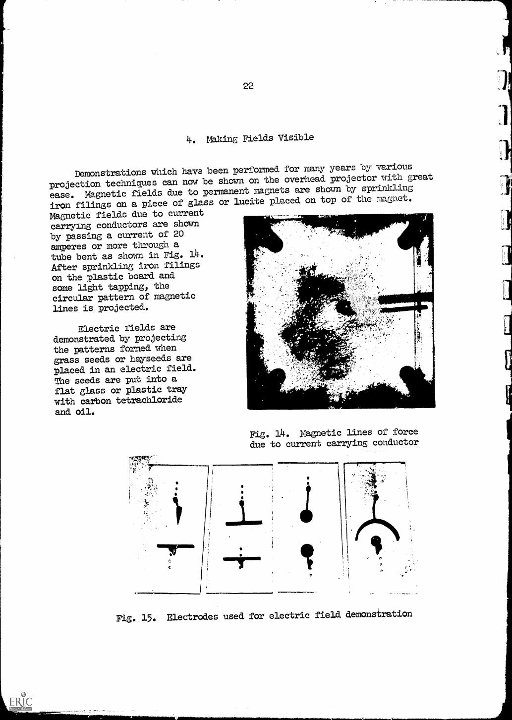
Magnetic fields due to current
carrying conductors are shown
by passing a current of 20
amperes or more through a
tube bent as shown in Fig. 14.
After sprinkling iron filings
on the plastic board and
some light tapping, thecircular pattern of magnetic
lines is projected.
Electric fields aredemonstrated by projectingthe patterns formed whengrass seeds or hayseeds are
placed in an electric field.
The seeds are put into a
flat glass or plastic tray
with carbon tetrachlorideand oil.
MINFig. 14. Magnetic lines of force
due to current carrying conductor
'101.111.0.101.11.....
Fig. 15. Electrodes used for electric field demonstration
23
Several thousand volts1 are applied across electrodes of various shapes -
as shown in Fig. 15 - partially submerged in the liquid. A metallic ring
placed into the field can be used to illustrate shielding.2
5. Shadow Projecting Models
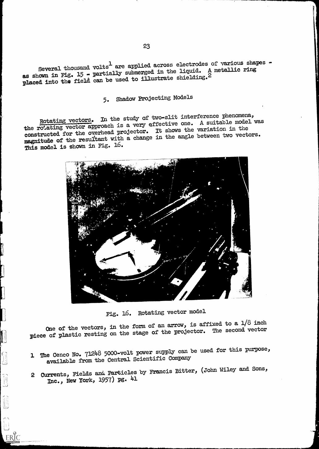
Rotating vectors. In the study of two-slit interference phenomena,
the rotating vector approach is a very effective one. A suitable model was
constructed for the overhead projector. It shows the variation in the
magnitude of the resultant with a change in the angle between two vectors.
This model is shown in Fig. 16.
Win.1101.u.
i.
fr c.
Fig, 16. Rotating vector model
One of the vectors, in the form of an arrow, is affixed to a 1/8 inch
piece of plastic resting on the stage of the projector. The second vector
1 The Cenco Na. 71248 5000-volt power supply can be used for this purpose,
available from the Central Scientific Company
2 Currents, Fields an Particles by Francis Bitter, (John Wiley and Sons,
Inc., New York, 1957) pg. 41
is on an 1/8 inch plastic disk which is rotated by hand around a pointcoinciding with the head of the first arrow. This is accomplished byglueing a small plug on the stationary plastic right at the head of tnearrow', and by drilling a small hole into the rotating disk at the tail endof its arrow.
The resultant is obtained by fastening a string to the head of therotating arrow and threading it through a plastic tube positioned above thetail of the stationary arrow. This tube is held. by a plastic arm on theprojector, as shown in Fig. 16. The string passes over pulleys along thearm to a counterweight behind the projector.
When the rotating vector is turned by hand, the resultant (shadow ofthe string) is observed to vary, giving a minimum at an angle of 0 and360° between then wo vectors, while a maximum resultant is obtained whenthe angle is 180.
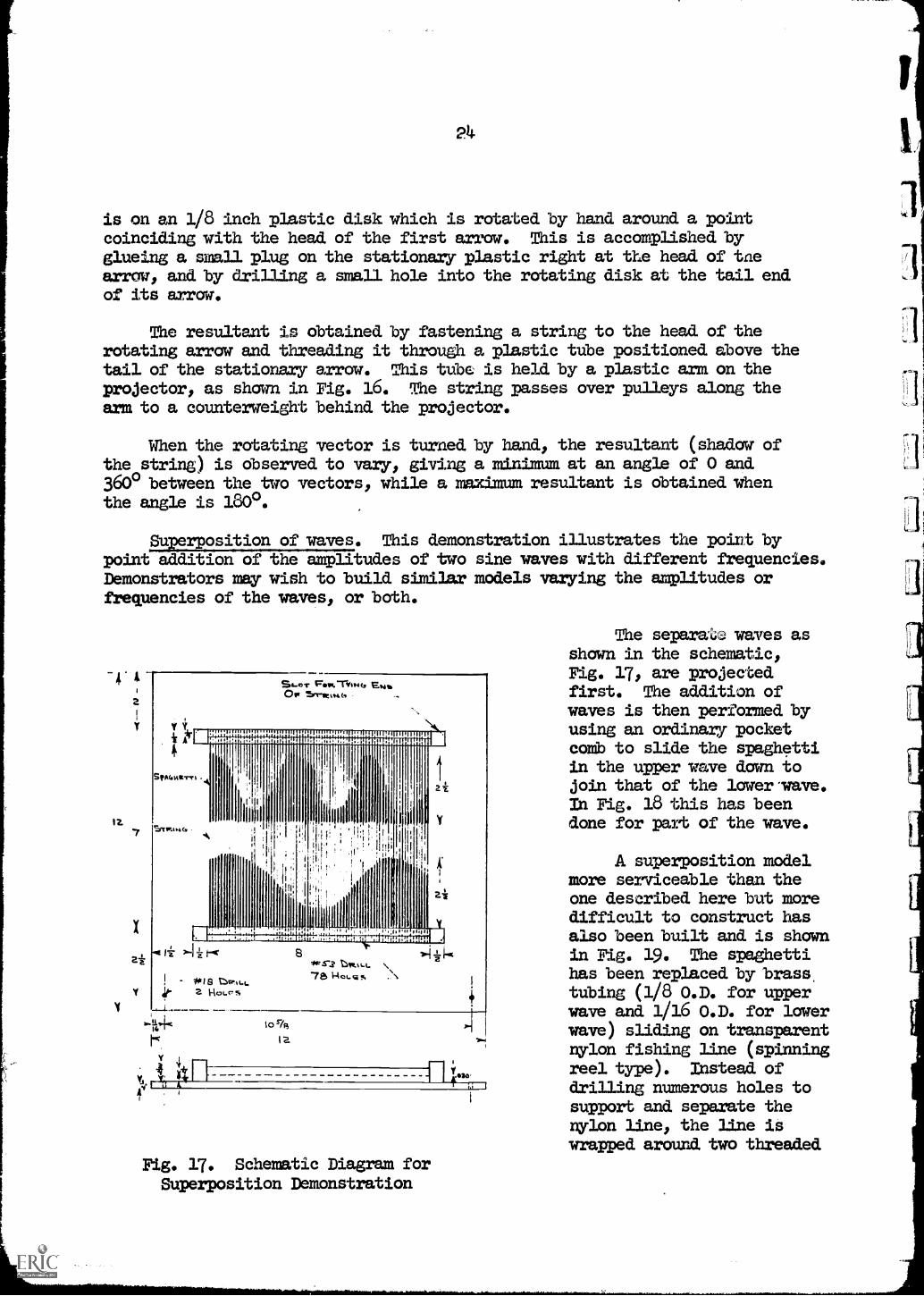
Superposition of waves. This demonstration illustrates the point bypoint addition of the amplitudes of two sine waves with different frequencies.Demonstrators may wish to build similar models varying the amplitudes orfrequencies of the waves, or both.
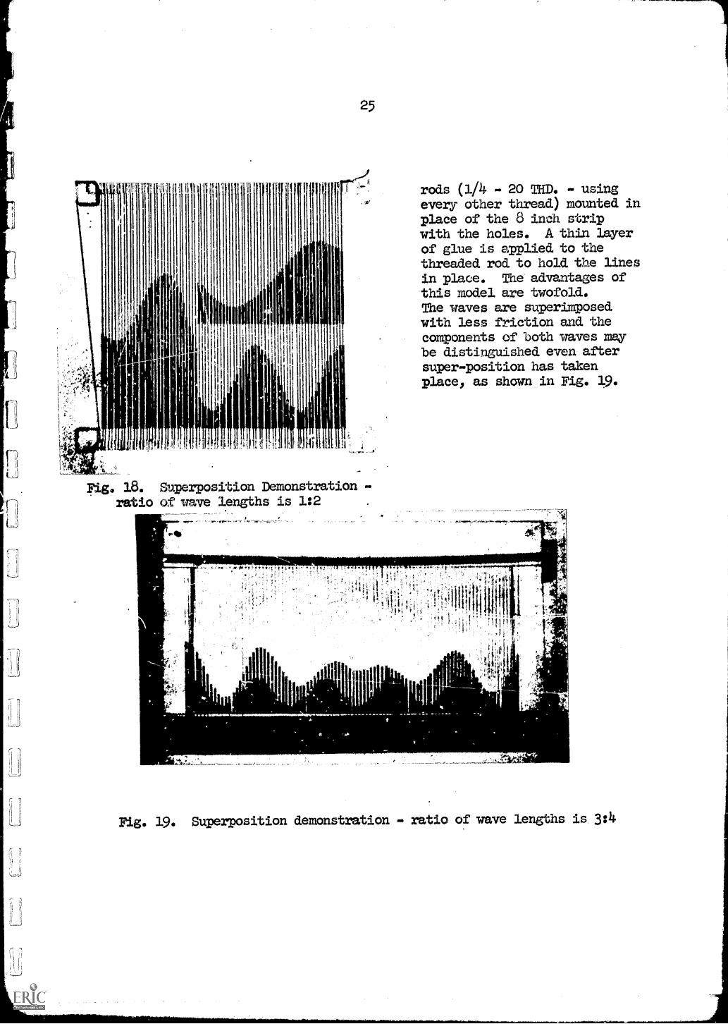
The separate waves asshown in the schematic,Fig. 17, are projectedfirst. The addition ofwaves is then performed byusing an ordinary pocketcomb to slide the spaghettiin the upper wave down tojoin that of the lower wave.In Fig. 18 this has beendone for part of the wave.
A superposition modelmore serviceable than theone described here but moredifficult to construct hasalso been built and is shownin Fig. 19. The spaghettihas been replaced by brass.tubing (1/8 O.D. for upperwave and 1/16 0.14 for lowerwave) sliding on transparentnylon fishing line (spinningreel type). Instead ofdrilling numerous holes tosupport and separate thenylon line, the line iswrapped around two threaded
25
Fig. 18. Superposition Demonstration -ratio of wave lengths is 1:2
rods (1/4 - 20 TED. - usingevery other thread) mounted inplace of the 6 inch stripwith the holes. A thin layerof glue is applied to thethreaded rod to hold the linesin place. The advantages ofthis model are twofold.The waves are superimposedwith less friction and thecomponents of both waves maybe distinguished even aftersuper-position has takenplace: as shown in Fig. 19.
Fig. 19. Superposition demonstration - ratio of wave lengths is 3:4
26
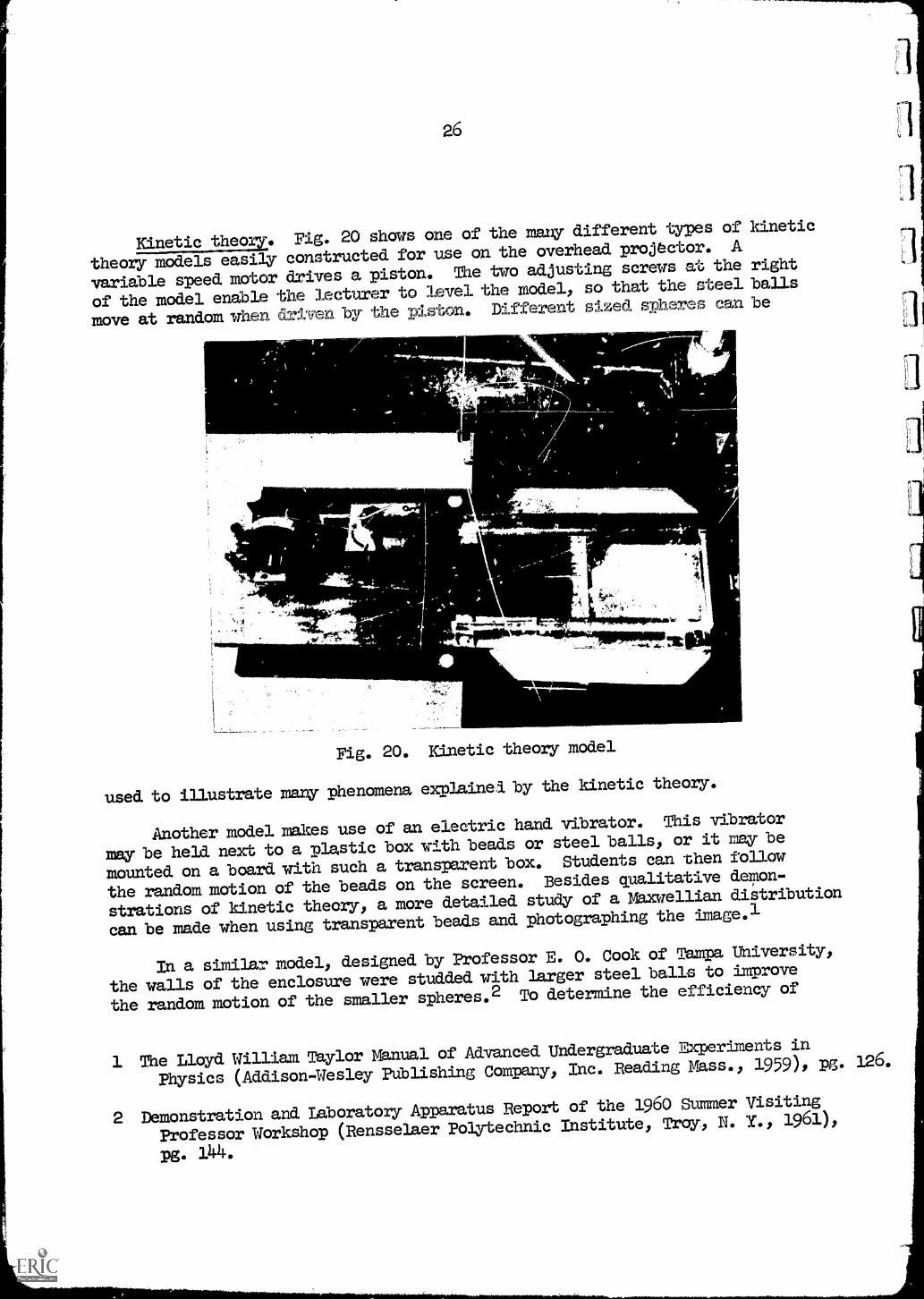
Kinetic theory. Fig. 20 shows one of the many different types of kinetic
theory models easily constructed for use on the overhead projector. A
variable speed motor drives a piston. The two adjusting screws at the right
of the model enable the lecturer to level the model, so that the steel balls
move at random when driven by the iston. Different sized spheres can be
A/44'
,47misiL
Fig. 20.20. Kinetic theory model
used to illustrate many phenomena explained by the kinetic theory.
Another model makes use of an electric hand vibrator. This vibrator
may be held next to a plastic box with beads or steel balls, or it may be
mounted on a board with such a transparent box. Students can then follow
the random motion of the beads on the screen. Besides qualitative demon-
strations of kinetic theory, a more detailed study of a Maxwellian distribution
can be made when using transparent beads and photographing the image.1
In a similar model, designed by Professor E. 0. Cook of Tampa University,
the walls of the enclosure were studded with larger steel balls to improve
the random motion of the smaller spheres.2 To determine the efficiency of
1 The Lloyd William Taylor Manual of Advanced Undergraduate Experiments in
Physics (Addison-Wesley Publishing Company, Inc. Reading Mass., 1959), pg. 126.
2 Demonstration and Laboratory Apparatus Report of the 1960 Summer Visiting
Professor Workshop (Rensselaer Polytechnic Institute, Troy, N. IL, 1961),
pg. 144.
27
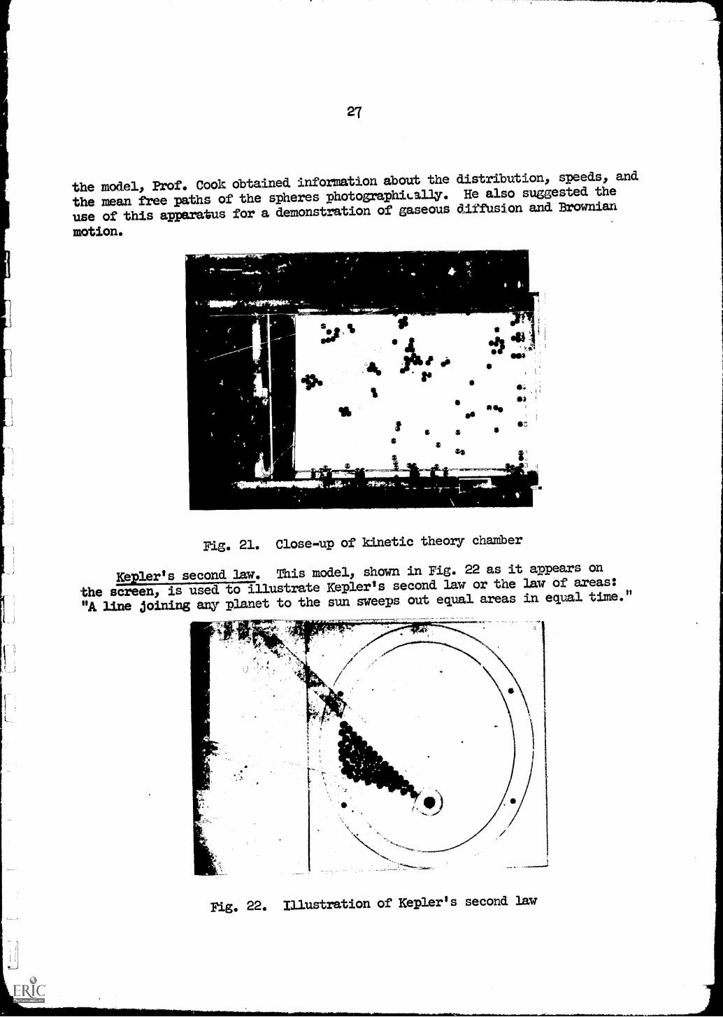
the model, Prof. Cook obtained information about the distribution, speeds, and
the mean free paths of the spheres photographiLally. He also suggested the
use of this apparatus for a demonstration of gaseous diffusion and Brownian
motion.
90a'
I
ta
.50 4
003
04
1sS:
-171"(44VM-41tr:
Fig. 21. Close-up of kinetic theory chamber
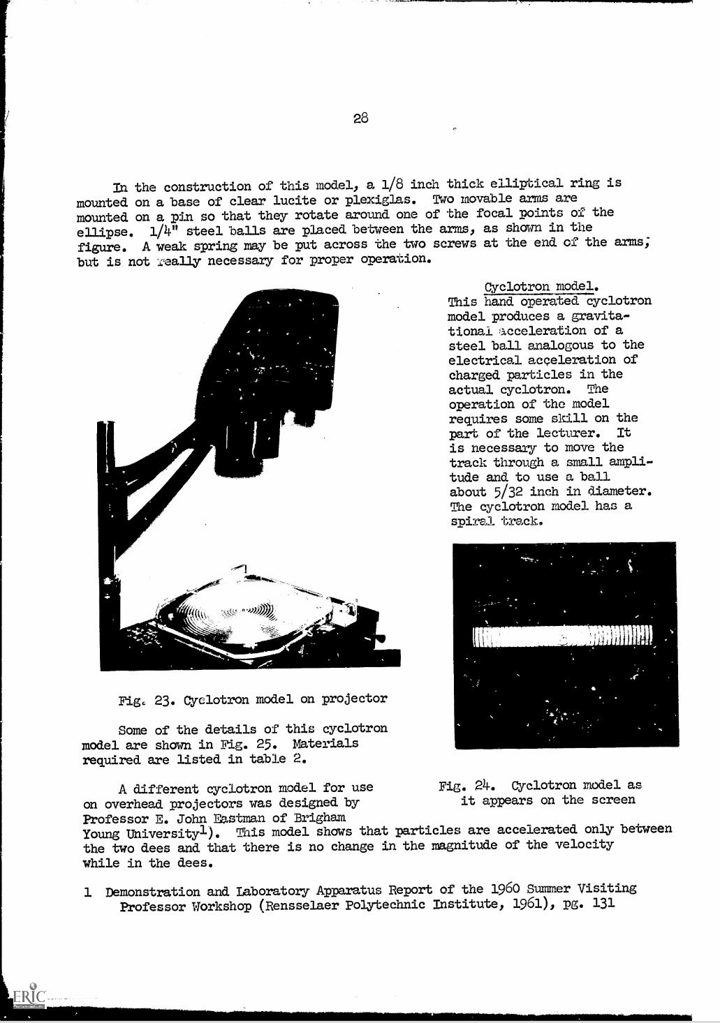
Kepler's second law. This model, shown in Fig. 22 as it appears on
the screen, is used to illustrate Kepler's second law or the law of areas:
"A line joining any planet to the sun sweeps out equal areas in equal time."
Fig. 22. Illustration of Kepler's second law
28
In the construction of this model, a 1/8 inch thick elliptical ring is
mounted on a base of clear lucite or plexiglas. Two movable arms are
mounted on a pin so that they rotate around one of the focal points of the
ellipse. 1/4" steel balls are placed between the arms, as shown in the
figure. A. weak spring may be put across the two screws at the end of the arms;
but is not ,really necessary for proper operation.
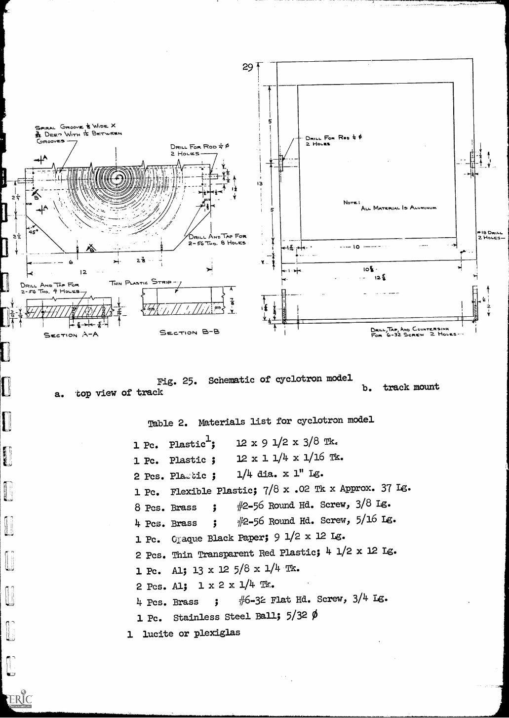
Fig. 23. Cyclotron model on projector
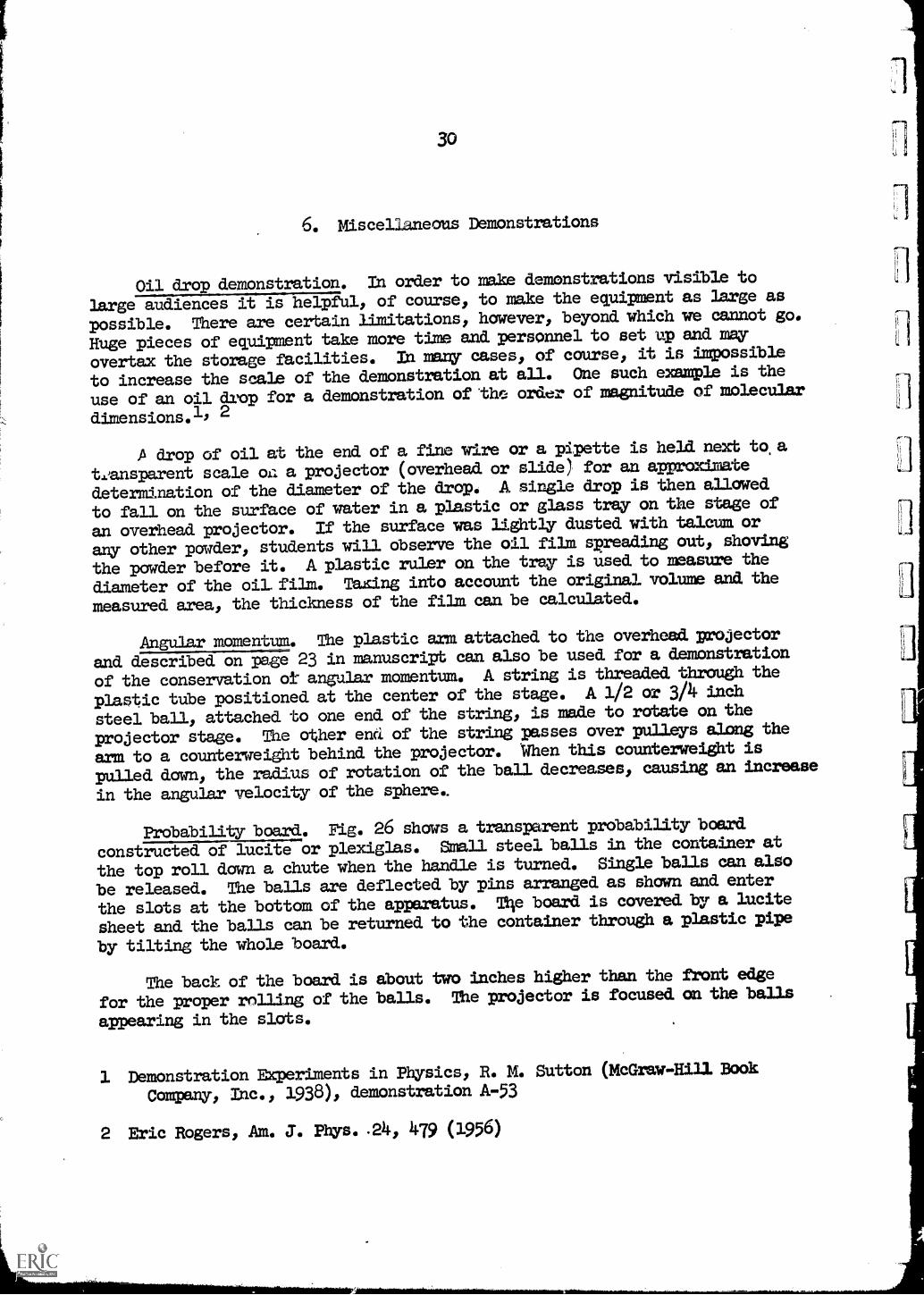
Some of the details of this cyclotronmodel are shown in Fig. 25. Materialsrequired are listed in table 2.
Cyclotron model.This hand operated cyclotronmodel produces a gravita-tional acceleration of asteel ball analogous to theelectrical acceleration ofcharged particles in theactual cyclotron. The
operation of the modelrequires some skill on thepart of the lecturer. It
is necessary to move thetrack through a small ampli-tude and to use a ballabout 5/32 inch in diameter.The cyclotron model has aspiral track..
A different cyclotron model for use Fig. 24. Cyclotron model as
on overhead projectors was designed by it appears on the screen
Professor E. John Eastman of BrighamYoung Universityl). This model shows that particles are accelerated only between
the two dees and that there is no change in the magnitude of the velocity
while in the dees.
1 Demonstration and Laboratory Apparatus Report of the 1960 Summer Visiting
Professor Workshop (Rensselaer Polytechnic Institute, 1961), pg. 131
1 Ft. Flexible Plastic; 7/8 x .02 Tk x Approx. 37 Lg.
8 Pes. Brass ; #2 -56 Round Hd. Screw, 3/8 Lg.
4 Pcs. Brass ; ?1/2-56 Round Hd. Screw, 5/16 Lg.
1 Pc. Q.:aque Black Paper; 9 1/2 x 12 Lg.
2 Pcs. Thin Transparent Red Plastic; 4 1/2 x 12 Lg.
1 Ft. Al; 13 x 12 5/8 x 1/4 Tk.
2 Ets. Al; 1 x 2 x 1/4 Tk.
4 Pcs. Brass ; #6-32 Flat Hd. Screw, 3/4 Lg.
1 Pc. Stainless Steel Ball; 5/32 0
1 lucite or plexiglas
0.18 Dwo-t-2.
30
6. Miscellaneous Demonstrations
Oil drop demonstration. In order to make demonstrations visible to
large audiences it is helpful, of course, to make the equipment as large as
possible. There are certain limitations, however, beyond which we cannot go.
Huge pieces of equipment take more time and personnel to set up and may
overtax the storage facilities. In many cases, of course, it is impossible
to increase the scale of the demonstration at all. One such example is the
use of an oil drop for a demonstration of the order of magnitude of molecular
dimensions.10 2
A drop of oil at the end of a fine wire or a pipette is held next to a
t,Ansparent scale o.c. a projector (overhead or slide) for an approximate
determination of the diameter of the drop. A single drop is then allowed
to fall on the surface of water in a plastic or glass tray on the stage of
an overhead projector. If the surface was lightly dusted with talcum or
any other powder, students will observe the oil film spreading out, shoving
the powder before it. A plastic ruler on the tray is used to measure the
diameter of the oil. film. Taxing into account the original volume and the
measured area, the thickness of the film can be calculated.
Angular momentum. The plastic arm attached to the overhead projector
and described on page 23 in manuscript can also be used for a demonstration
of the conservation of angular momentum. A string is threaded through the
plastic tube positioned at the center of the stage. A 1/2 or 3/4 inch
steel ball, attached to one end of the string, is made to rotate on the
projector stage. The other end of the string passes over pulleys along the
arm to a counterweight behind the projector. When this counterweight is
pulled down, the radius of rotation of the ball decreases, causing an increase
in the angular velocity of the sphere..
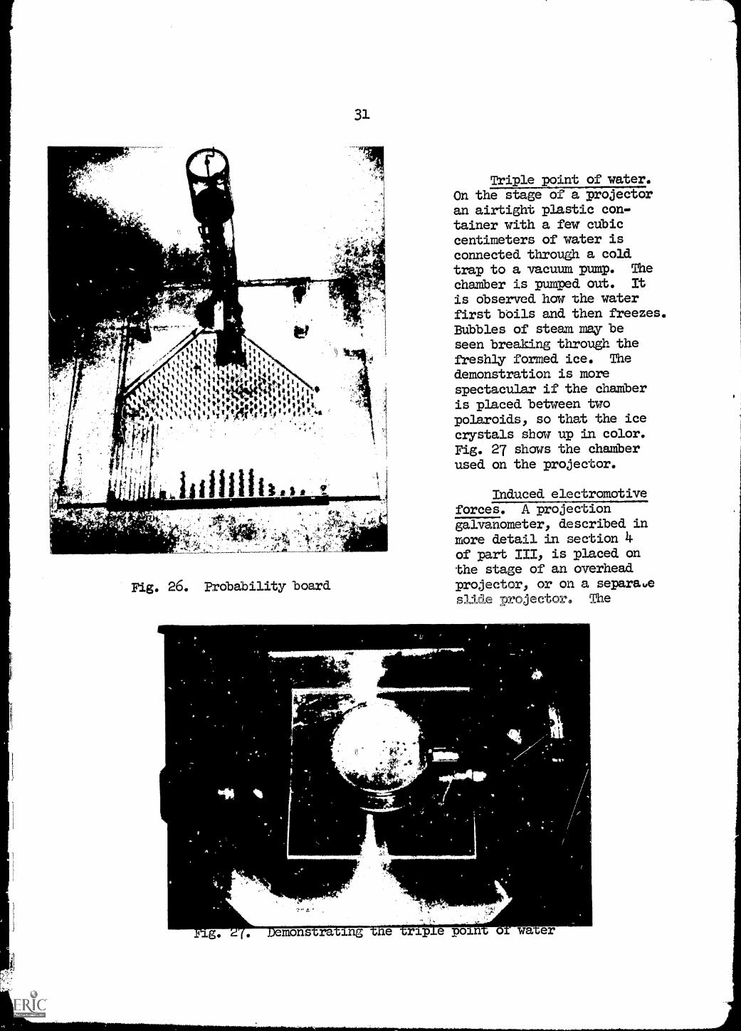
Probability board. Fig. 26 shows a transparent probability board
constructed of lucite or plexiglas. Small steel balls in the container at
the top roll down a chute when the handle is turned. Single balls can also
be released. The balls are deflected. by pins arranged as shown and enter
the slots at the bottom of the apparatus. Tile board is covered by a lucite
sheet and the balls can be returned to the container through a plastic pipe
by tilting the whole board.
The back of the board is about two inches higher than the front edge
for the proper rolling of the balls. The projector is focused on the balls
appearing in the slots.
1 Demonstration Experiments in Physics, R. M. Sutton (McGraw -Hill Book
Company, Inc 1938), demonstration A-53
2 Eric Rogers, Am. J. Phys. .24, 479 (1956)
31
Fig. 26. Probability board
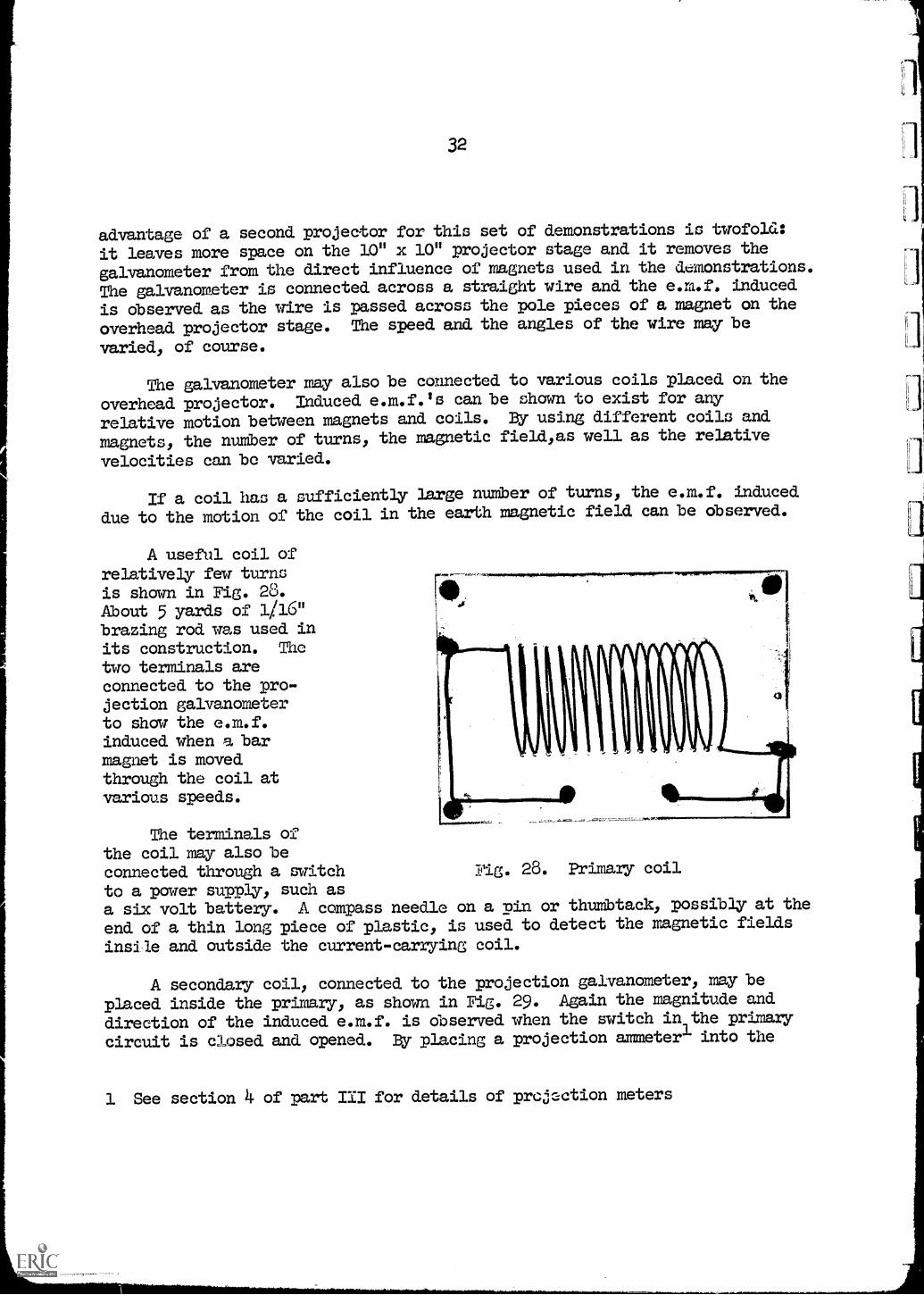
Triple point of water.On the stage of a projectoran airtight plastic con-tainer with a few cubiccentimeters of water isconnected through a coldtrap to a vacuum pump. The
chamber is pumped out. It
is observed how the waterfirst boils and then freezes.Bubbles of steam may beseen breaking through thefreshly formed ice. Thedemonstration is morespectacular if the chamberis placed between twopolaroids, so that the icecrystals show up in color.Fig. 27 shows the chamberused on the projector.
Induced electromotiveforces. A projectiongalvanometer, described inmore detail in section 4of part III, is placed onthe stage of an overheadprojector, or on a separaueslide projector. The
t fw
ig. mons ra ing rip e poin o wa er
32
advantage of a second projector for this set of demonstrations is twofold,:
it leaves more space on the 10" x 10" projector stage and it removes the
galvanometer from the direct influence of magnets used in the demonstrations.
The galvanometer is connected across a straight wire and the e.m.f. induced
is observed as the wire is passed across the pole pieces of a magnet on the
overhead projector stage. The speed and the angles of the wire may be
varied, of course.
The galvanometer may also be connected to various coils placed on the
overhead projector. Induced e.m.f.ls can be shown to exist for any
relative motion between magnets and coils. By using different coils and
magnets, the number of turns, the magnetic field/as well as the relative
velocities can be varied.
If a coil has a sufficiently large number of turns, the e m f induced
due to the motion of the coil in the earth magnetic field can be observed.
A useful coil ofrelatively few turnsis shown in Fig. 28.About 5 yards of 1/16"brazing rod was used inits construction. The
two terminals areconnected to the pro-jection galvanometerto show the e m finduced when a barmagnet is movedthrough the coil atvarious speeds.
The terminals ofthe coil may also beconnected through a switchto a power supply, such asa six volt battery. A compass needle on a pin or thumbtack, possibly at the
end of a thin long piece of plastic, is used to detect the magnetic fields
insile and outside the current-carrying coil.
Fig. 28. Primary coil
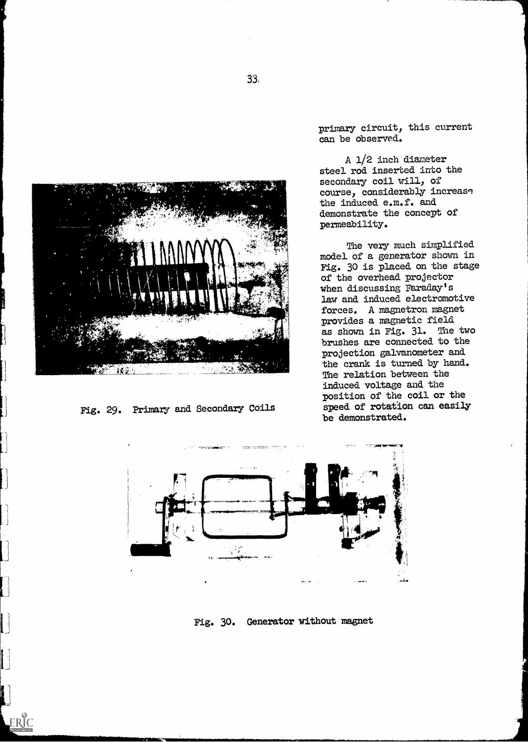
A secondary coil, connected to the projection galvanometer, may be
placed inside the primary, as shown in Fig. 29. Again the magnitude and
direction of the induced e.m.f. is observed when the switch in the primary
circuit is closed and opened. By placing a projection ammeterl into the
1 See section 4 of part III for details of projection meters
33.
Fig. 29. Primary and Secondary Coils
primary circuit, this currentcan be observed.
A 1/2 inch diametersteel rod inserted into thesecondary coil will, ofcourse, considerably increas'
the induced e.m.f. anddemonstrate the concept ofpermeability.
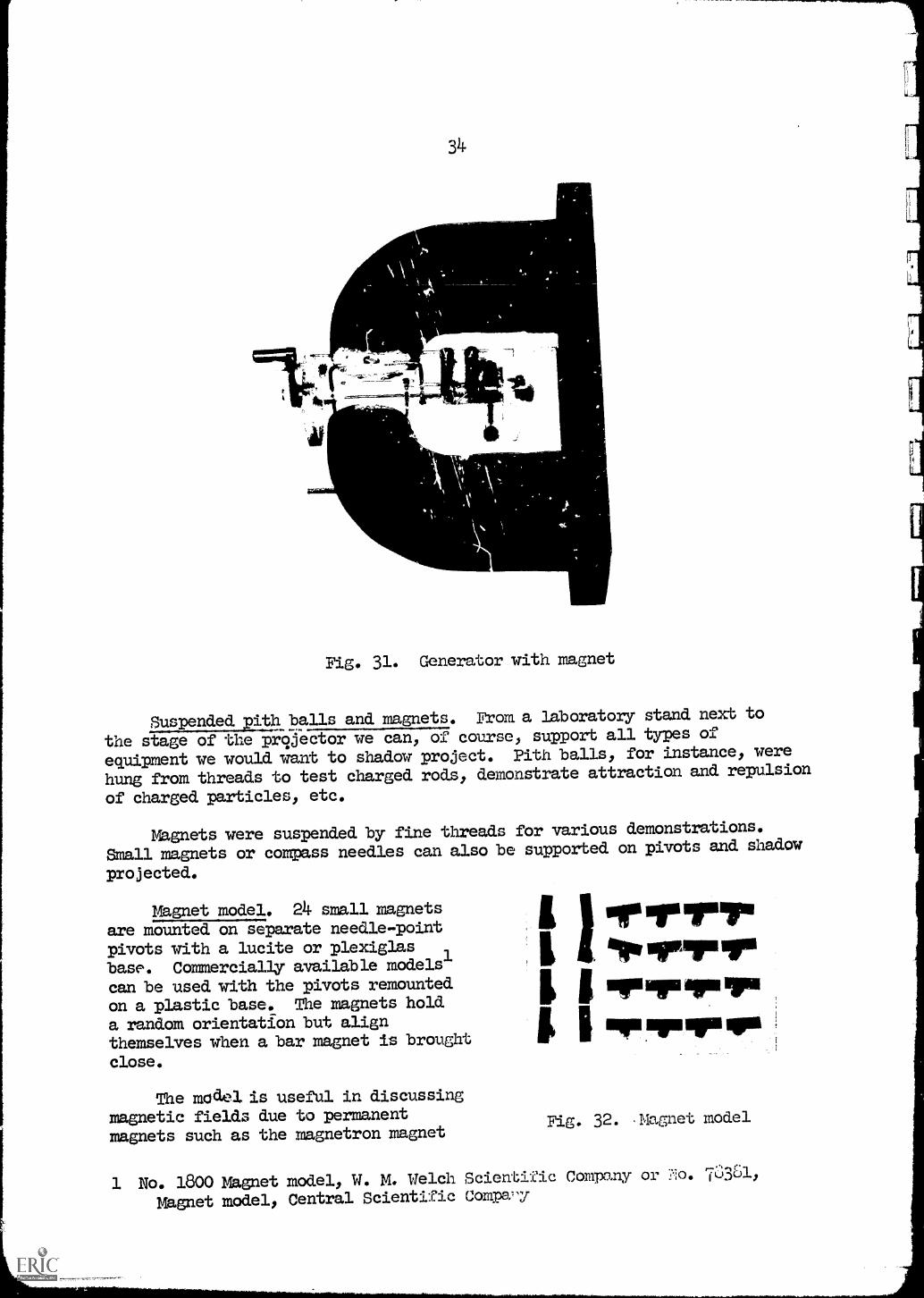
The very much simplifiedmodel of a generator shown inFig. 30 is placed on the stageof the overhead projectorwhen discussing Faraday'slaw and induced electromotiveforces. A magnetron magnetprovides a magnetic fieldas shown in Fig. 31. The twobrushes are connected to theprojection galvanometer andthe crank is turned by hand.The relation between theinduced voltage and theposition of the coil or thespeed of rotation can easilybe demonstrated.
Fig. 30. Generator without magnet
311.
OP
4011=1--or-07Nriw
The
IVC
Fig. 31. Generator with magnet
Suspended pith balls and magnets. From a laboratory stand next to
the stage of the pr9jector we can, of course, support all types of
equipment we would want to shadow project. Pith balls, for instance, were
hung from threads to test charged rods, demonstrate attraction and repulsion
of charged particles, etc.
Magnets were suspended by fine threads for various demonstrations.
Small magnets or compass needles can also be supported on pivots and shadow
projected.
Magnet model. 24 small magnetsare mounted on separate needle-pointpivots with a lucite or plexiglasbase. Commercially available models'can be used with the pivots remounted
on a plastic base. The magnets hold
a random orientation but alignthemselves when a bar magnet is brought
close.
model.model. is useful in discussingmagnetic fields due to permanentmagnets such as the magnetron magnet
I I arervurI IprvirririirfairmsdriarlI irilirompqp.
Fig. 32. Magnet model
1 No. 1800 Magnet model, W. Ph Welch Scientific Company or *:o. 73361,
Magnet model, Central Scientific Com:pa-y
35
'used in other demonstrations. When this magnet is placed onto the stage of
the projector, the model will show the direction of the lines of force.
This demonstration is particularly useful when discussing magnetic
properties and ferromagnetic domains.
7. Using the Projector Lens Only
There are situations where the light source of the projector maybe
replaced by a different source, using just the lens system for projection
purposes. One example is the use of a cathode ray tube commercially avail-
able to,,demonstrate deflections of charged particles due to -Ed etic
The tube is first shadow-projected,'making use of the overhead projector
light source. When the spark coil supplying the high voltage across the
tube is turned on, the projector light is turned off and the greenish
looking electron beam is focused onto the screen. A magnet brought close
to the tube will deflect the beam. The magnet can also be shadow-projected
first. For the electron beam to be clearly visible, however, the room has
to be in complete darkness.
The projector lens has also been used to project patterns from high
intensity oscilloscopes2, but, once again, the room has to be darkened to
clearly observe this "projection oscilloscope".
1 No. 71555, Central Scientific Company or No. 2145, W. M...Welch Scientific
Company
2 Type 543 Oscilloscope, Tetronix, Inc., Portland, Oregon
36
PART III
BREAD-BOARD FOR ELECTRICAL CONNECTIONS1
1. The Projection of Circuits
The use of conventional circuit diagrams for electrical wiring is, of
course, very useful at all levels of instruction. Many times, however,
students do not have the opportunity to see an actual circuit in operation
and therefore do not get a feeling for the physical dimensions of the
components or the order of magnitude of the electrical quantities involved.
This poses a difficult problem for the lecturer because actual electrical
components are - in general . too small to be seen by a large class and
large models do not use realistic parts. Ordinary electrical meters cannot
be used, but must be projected in some manner to be visible in a classroom.
The overhead projector is first used to show a circuit diagram on a
transparency. After a discussion of the diagram by the lecturer, the actual
working circuit, mounted on a transparent bread board, is superimposed on
the circuit diagram and the projector is fortsed. Projection meters are
used for reading the various electrical quantities of interest and are
placed on the lower part of the projection stage.
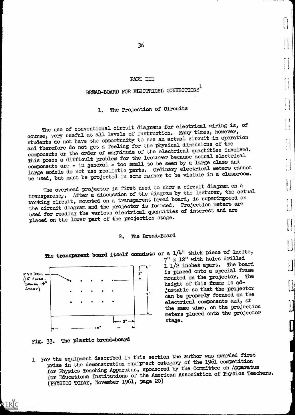
2. The Bread-Board
The transparent board itself consists
0.93 DRILLOr HamsSPA % I +"APARr)
o
31g. 33. The plastic bread-board
t
a"
7"
of a 1/4" thick piece 'of lucite,
7" x 12" with holes drilled
1 1/2 inche6 apart. The board
is placed onto a special frame
mounted on the projector. The
height of this frame is ad-
justable so that the projector
can be properly focused on the
electrical components and, at
the same .6ime, on the projection
meters placed onto the projector
stage.
1 For the equipment described in this section the author was awarded first
prize in the demonstration equipment category of the 1961 competition
for Physics Teaching Apparatus, sponsored by the Committee on Apparatus
for Educationa Institutions of the American Association of Physics Teachers.
(PHYSICS TODAY, November 1961, page 20)
37
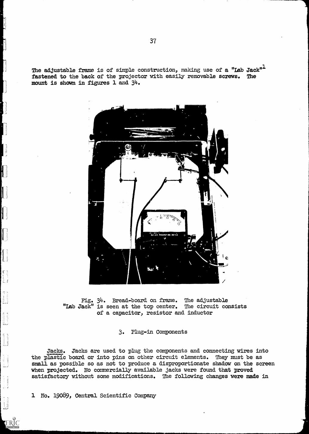
The adjustable frame is of simple construction, making use of a "Lab Jack"1fastened to the back of the projector with easily removable screws. Themount is shown in figures 1 and 34.
040-
11
e
+.1
Fig. 34. Bread-board on frame. The adjustable"Lab Jack" is seen at the top center. The circuit consists
of a capacitor, resistor and inductor
3. Plug-in Components
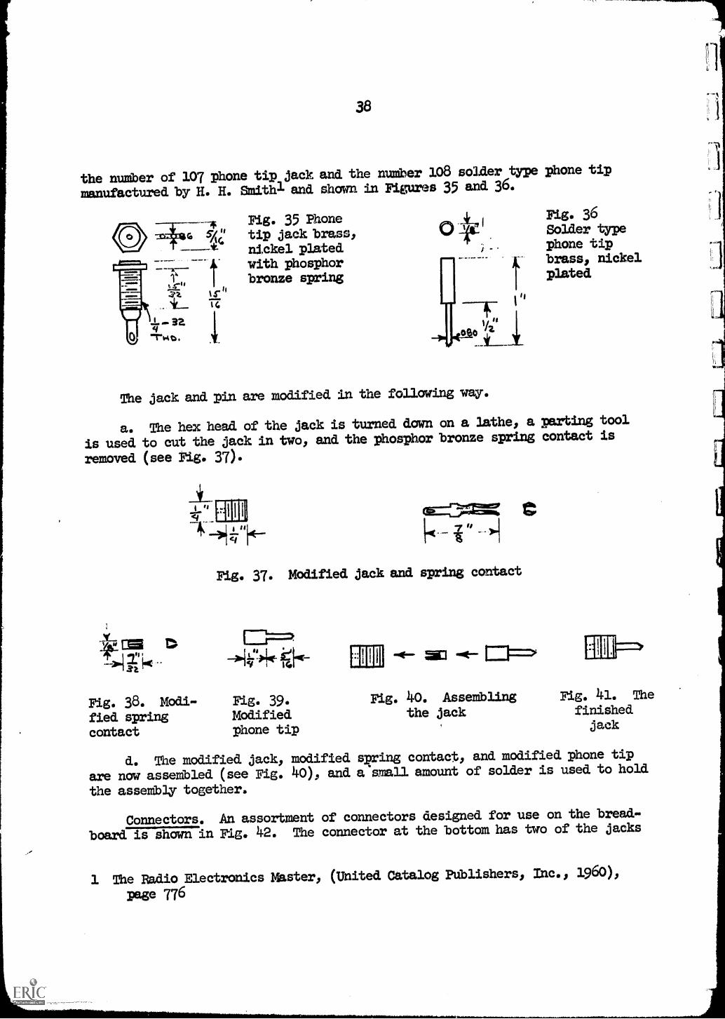
Jacks. Jacks are used to plug the components and connecting wires intothe plastic board or into pins on other circuit elements. They must be assmall as possible so as not to produce a disproportionate shadow on the screenwhen projected. No commercially available jacks were found that provedsatisfactory without some modifications. The following changes were made in
1 No. 19089, Central Scientific Company
38
the number of 107 phone tip jack and the number 108 solder type phone tip
manufactured. by H. H. Smithl and shown in Figures 35 and 36.
Fig. 35 Phonetip jack brass,nickel platedwith phosphorbronze spring
The jack and pin are modified in the following way.
Fig. 36Solder typephone tipbrass, nickelplated
a. The hex head of the jack is turned dawn on a lathe, a parting tool
is used to cut the jack in two, and the phosphor bronze spring contact is
removed (see Fig. 37).
I 'S
Fig. 38. Modi-fied springcontact
1001
Fig. 37. Modified jack and spring contact
Pig. 39.Modifiedphone tip
-4- WO -NE- 1==.
Fig. 40. Assembling Fig. 41. The
the jack finishedjack
d. The modified jack, modified spring contact, and modified phone tip
are now assembled (see Fig. 40), and a small amount of solder is used to hold
the assembly together.
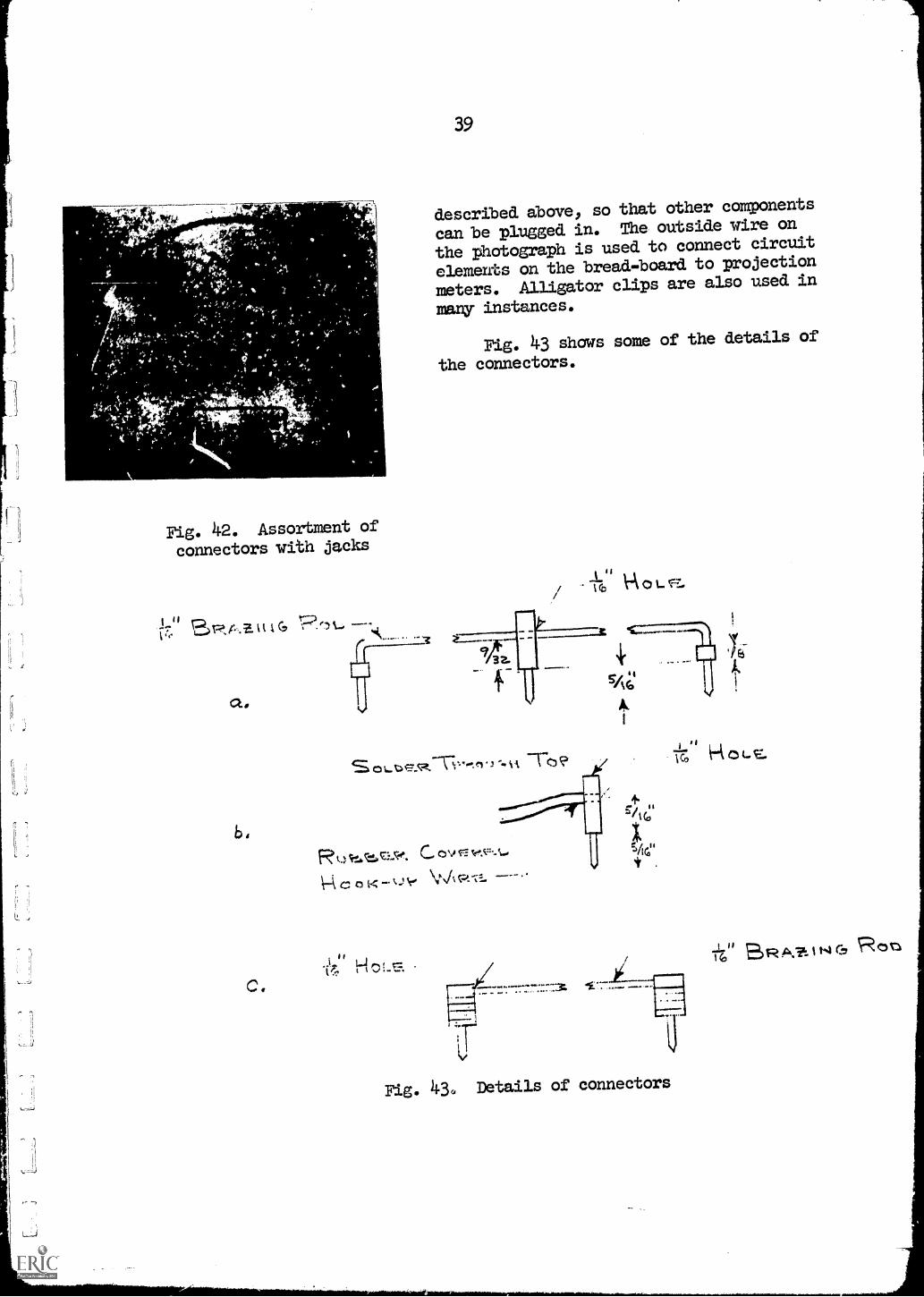
Connectors. An assortment of connectors designed for use on the bread-
board is shown in Fig. 42. The connector at the bottom has two of the jacks
1 The Radio Electronics Master, (United Catalog Publishers, Inc., 1960),
page 776
"r0
S 1 Z.
4
Fig. 42. Assortment of
connectors with jacks
1" tt IG
a.,
b.
C.
39
described above, so that other components
can be plugged in. The outside wire on
the photograph is used to connect circuit
elements on the bread-board to projection
meters. Alligator clips are also used in
many instances.
Fig. 43 shows some of the details of
the connectors.
II scp 1OL.
SOLD *"..t "TO?
Rt. C
0 K A c.
-I aV.
I ra
M/1
4.
I "IG, rnoLE.
Fig. 43. Details of connectors
.1016 RC, 0;3 r1T--,
40
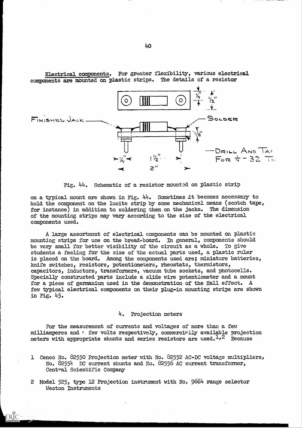
For greater flexibility, various electrical
components are mounted on plastic strips. The details of a resistor
rb; uu
4 *-4, "
a">--
St)L..tbER
ANT:)-7-",iv;
Fo ;
Fig. 44. Schematic of a resistor mounted on plastic strip
on a typical mount are shown in Fig. 44. Sometimes at becomes necessary tohold the component on the lucite strip by some mechanical means (scotch tape,
for instance) in addition to soldering them on the jacks. The dimensionof the mounting strips may vary according to the size of the electricalcomponents used.
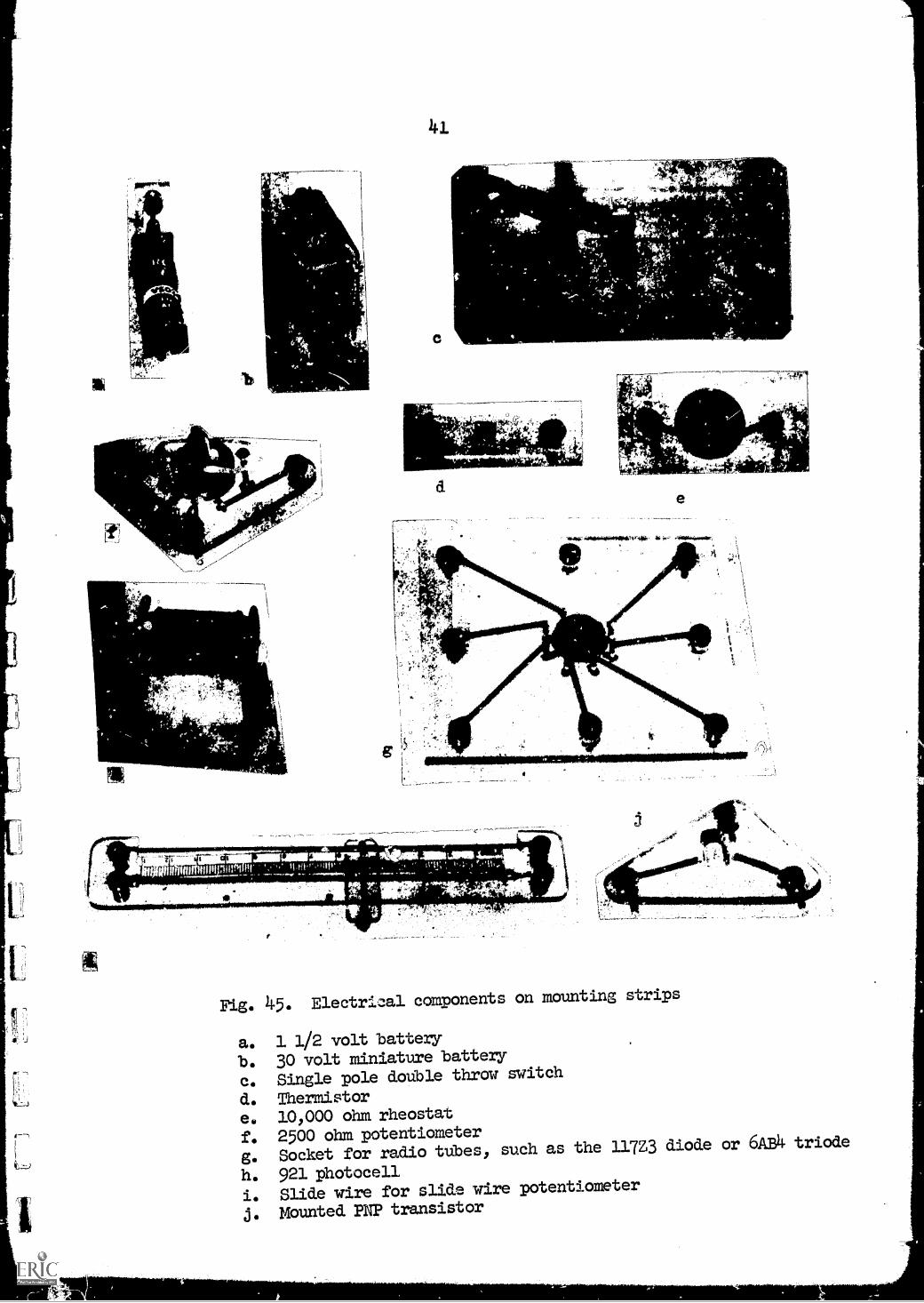
A large assortment of electrical components can be mounted on plasticmounting strips for use on the bread-board. In general, components shouldbe very small for better visibility of the circuit as a whole. To givestudents a feeling for the size of the actual parts used, a plastic ruleris placed on the board. Among the components used are; miniature batteries,knife switches, resistors, potentiometers, rheostats, thermistors,capacitors, inductors, transformers, vacuum tube sockets, and photocells.Specially constructed parts include a slide wire potentiometer and a mountfor a piece of germanium used in the demonstration of the Hall effect. Afew typical electrical components on their plug-in mounting strips are shownin Fig. 45.
4. Projection meters
For the measurement of currents and voltages of more than a feumilliamperes and r, few volts respectively, commercielly available projectionmeters with appropriate shunts and series resistors are used. -'2 Because
1 Cenco No. 82550 Projection meter with No. 82552 AC-DC voltage multipliers,No. 82554 DC current shunts and No. 82556 AC current transformer,Central Scientific Company
2 Model 525, type 12 Projection instrument with No. 9664 range selectorWeston Instruments
Fig. 45. Electrical components on mounting strips
a. 1 1/2 volt battery
b. 30 volt miniature battery
c. Single pole double throw switch
d. Thermistore. 10,000 ohm rheostat
f. 2500 ohm potentiometer
g. Socket for radio tubes, such as the 1172 diode or 6AB4 triode
h. 921 photocell
i. Slide wire for slide wire potentiometer
j. Mounted PNP transistor
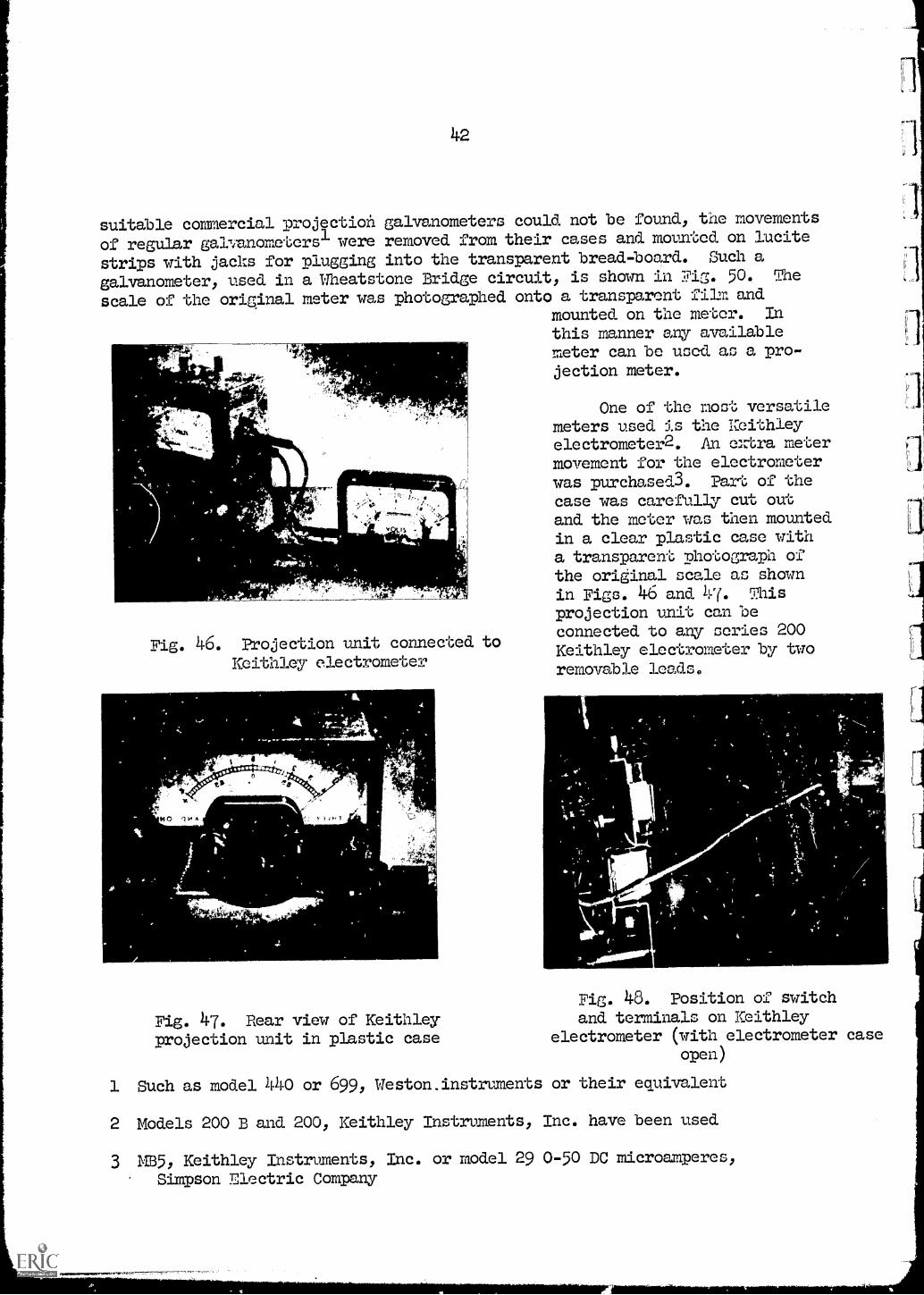
42
suitable commercial projection galvanometers could not be found, the movements
of regular galvanometersl were removed from their cases and mounted on Lucite
strips with jacks for plugging into the transparent bread-board. Such a
galvanometer, used in a Wheatstone Bridge circuit, is shown in Fig. 50. The
scale of the original meter was photographed onto a transparent film andmounted on the meter. Inthis manner any available
fYmeter can be used as a pro-jection meter.
=N
4
Fig. 46. Projection unit connected toKeithley electrometer
As0114"lizr-fr
One of the most versatilemeters used is the Keithleyelectrometer2. An extra metermovement for the electrometerwas purchased3. Part of thecase was carefully cut out
and the meter was then mountedin a clear plastic case witha transparent photograph ofthe original scale as shownin Figs. ).6 and 47. Thisprojection unit can beconnected to any series 200Keithley electrometer by tworemovable leads.
Fig. 48. Position of switch
Fig. 47. Rear view of Keithley and terminals on Keithley
projection unit in plastic case electrometer (with electrometer caseopen)
1 Such as model 440 or 699, Weston.instrwnents or their equivalent
2 Models 200 B and 200, Keithley Instruments, Inc. have been used
3 M3.5, Keithley Instruments, Inc. or model 29 0-50 DC microamperes,
Simpson Electric Company
1.3
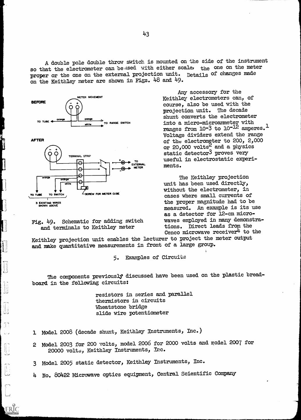
A double pole double throw switch is mounted on the side of the instrument
so that the electrometer can beased with either scale, the one on the meter
proper or the one on the external projection unit. Details of changes made
on the Keithley meter are shown in Figs. 48 and 49.
BEFORE
TO TUBE
AFTER
METER MOVEMENT
TO RANGE SWITCH
TERMINAL STRIP
.-41a-E,TTOMETER
Any accessory for theKeithley electrometers can, ofcourse, also be used with theprojection unit. The decadeshunt converts the electrometerinto a micro-microanneter withranges from 10-3 to 10-12 amperes.1Voltage dividers extend the rangeof the electrometer to 200, 2,000or 20,000 volts2 and a physicsstatic detector 3 proves veryuseful in electrostatic experi-ments.
The Keithley projectionunit has been used directly,
TO TUBE TO SWITCH SCREW FOR METER CASEwithout the electrometer, incases where small currents ofthe proper magnitude had to be
measured. An example is its useas a detector for 12-cm micro-
Fig. 49. Schematic for adding switch waves employed in many demonstra-
and terminals to Keithley meter tions. Direct leads from theCenco microwave receiver to the
Keithley projection unit enables the lecturer to project the meter output
and make quantitative measurements in front of a large group.
3 EXISTING WIRESSHOWN ABOVE
5. Examples of Circuits
The components previously` discussed have been used on the plastic bread-
board in the following circuits:
resistors in series and parallelthermistors in circuitsWheatstone bridgeslide wire potentiometer
1 Model 2008 (decade shunt, Keithley Instruments, Inc.)
2 Model 2003 for 200 volts, model 2006 for 2000 volts and go del 2007 for
20000 volt, Keithley Instruments, Inc.
3 Model 2005 static detector, Keithley Instruments, Inc.
4 Vb. 80422 Microwave optics equipment, Central Scientific Company
charge and discharge of capacitor
A. C. series or parallel circuitscharacteristics of diodes, triodes and transistors
photoelectric effectHall effect
In the case of the Hall effect demonstration, a separate plastic base
was used directly on the stage of the projector because of the weight of
the magnet involved. The components used, however, were of the plug-in type
previously described.
Two typical circuits using the bread-board and the Hall effect demon-
stration are shown in Figs. 50, 51 and 52.
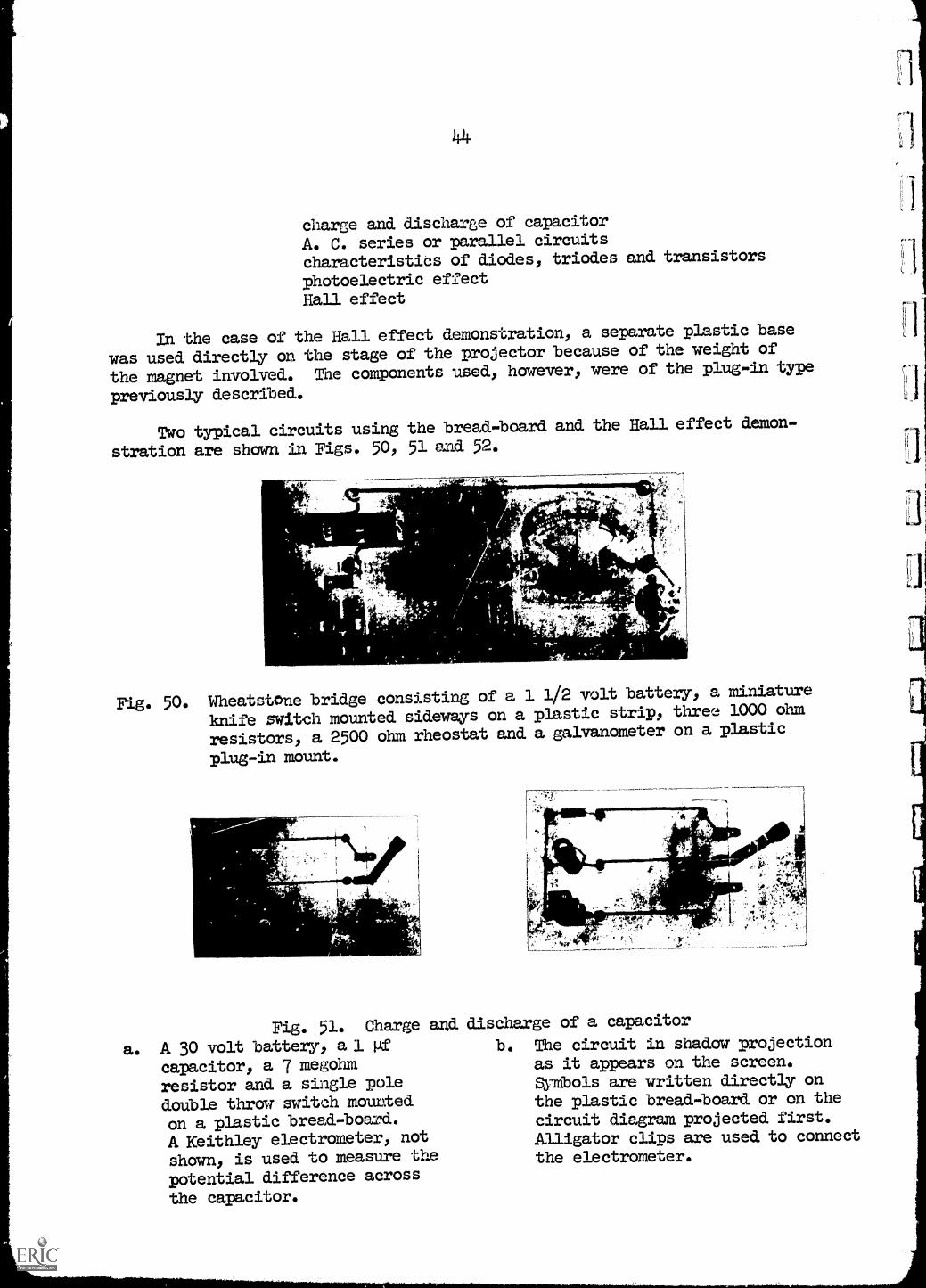
Fig. 50. Wheatstone bridge consisting of a 1 1/2 volt battery, a miniature
knife switch mounted sideways on a plastic strip, three 1000 ohm
resistors, a 2500 ohm rheostat and a galvanometer on a plastic
plug-in mount.
Fig. 51. Charge and
a. A 30 volt battery, al gfcapacitor, a 7 megohmresistor and a single pole
double throw switch mounted
on a plastic bread-board.
A Keithley electrometer, not
shown, is used to measure the
potential difference across
the capacitor.
discharge of a capacitor
b. The circuit in shadow projectionas it appears on the screen.Symbols are written directly onthe plastic bread-board or on the
circuit diagram projected first.Alligator clips are used to connectthe electrometer.
1_3
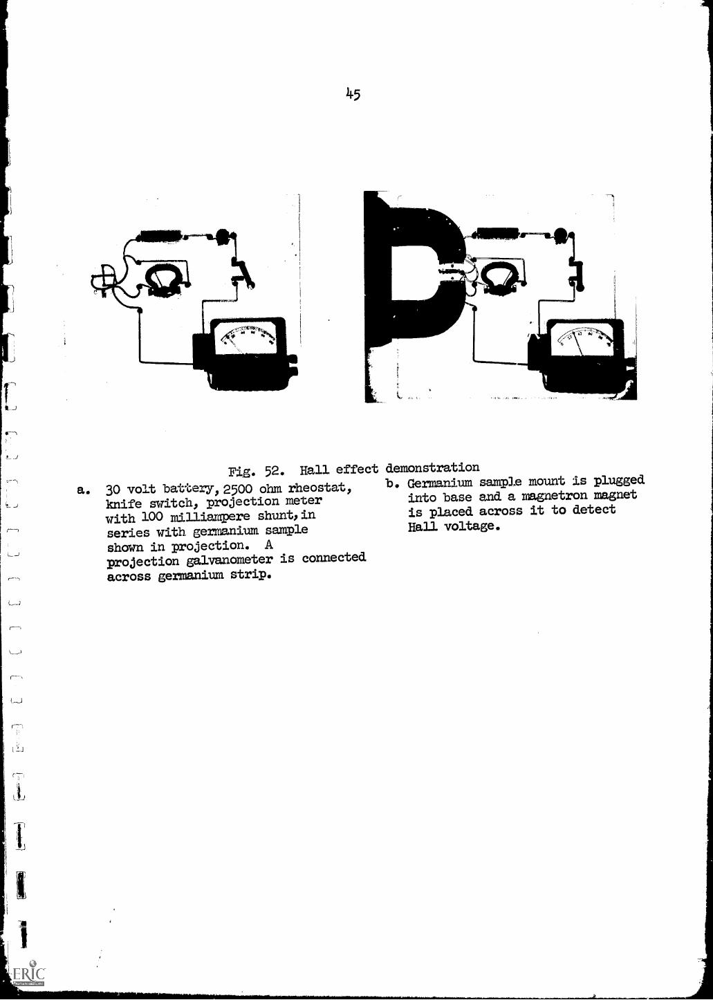
Fig. 52. Hall effect
a. 30 volt battery, 2500 ohm rheostat,knife switch, projection meter
with 100 milliampere shunt, in
series with germanium sample
shown in projection. Aprojection galvanometer is connected
across germanium strip.
demonstrationb. Germanium sample mount is plugged
into base and a magnetron magnet
is placed across it to detect
Hall voltage.
4.6
PART IV
AN X-Y PLOTTER OR THE OVERHEAD PROJECTOR
1. Purpose of the Plotter
In physics it is highly desirable to show functional relationships
between measurable quantities. An effortless procedure would be for the
lecturer to present the students with a graph, shown on the overhead pro-
jector or by any other means. This does not answer the question, however,
how these plots are actually obtained, nor does it give the student a
feeling for the experimental method of plotting variables first and then
trying to deduce the mathematical relationships. For this purpose, in many
of our research laboratory X-Y plotters or recorders are in use.
When we deal with a repetitive phenomenon, we could use an oscilloscope
to show such relationships. The relation between B and H for an iron ring,
resulting in a hysterisis curve, can be shown easily on an oscilloscope.
The convenience of using a frequency of 60 cycles per second is obvious.
When we want to demonstrate the relation between charge and time of a
charging or discharging capacitor, however, we do not deal with a repeti-
tive process, and an X-Y plotter is called for.
A commercially available recorder is not suitable for lecture
demonstrations given to large groups, because of the difficulty in making
the trace visible and the rather high Lost of such devices. For this
reason it was decided that an X-Y plotter should. be constructed to fit on
the stage of an ove.cnead projector thereby making the traces visible to
large audiences. Since the plotter would not be used for detailed quantita-
tive data, but only for qualitative demonstrations, it does not require the
accuracy most commercial recorders have. This, of course, would decrease
the cost app'eciable.
2. Description
With the purposes stated above in mind, such an X-Y plotter for overhead
projectors was designed and built at Rensselaer Polytechnic Institute and
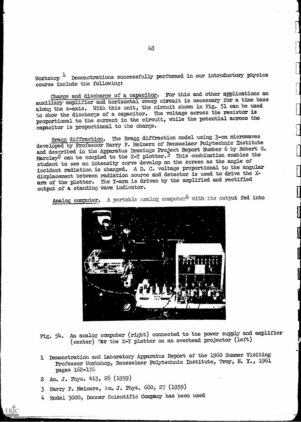
is shown in Fig. 53.1 Besides the plotting table shown, an additional unit,
consisting of a power supply and an amplifier, is required and is shown in
Fig. 54.
1 The R.' P. X-Y plotter was designed by George F. Robinsor of the
Department of Physics. This project was partially supported by the
General Electric Educational and Charitable Trust.
1
VV.
4
t_
ilt.14,_" 1" ta
ihiLt4WNMIMuy
47
miloc==--
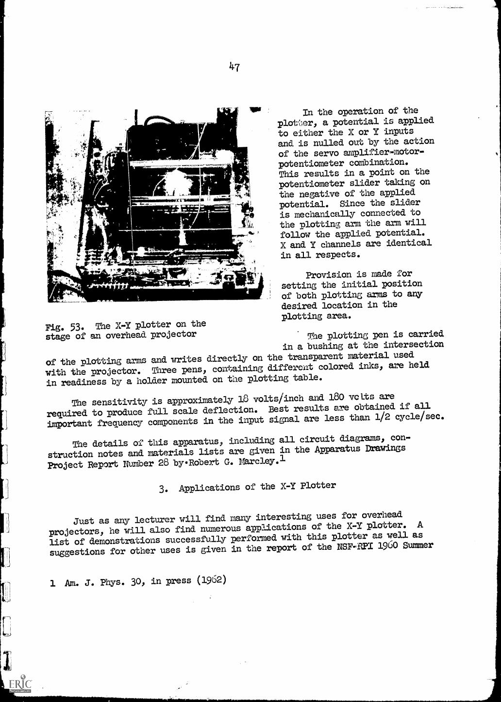
Fig. 53. The X-Y plotter on the
stage of an overhead projector
In the operation of the
plotter, a potential is applied
to either the X or Y inputs
and is nulled out by the action
of the servo amplifier-motor-potentiometer combination.This results in a point on the
potentiometer slider taking onthe negative of the applied
potential. Since the slider
is mechanically connected tothe plotting arm the arm will
follow the applied potential.
X and Y channels are identical
in all respects.
Provision is made forsetting the initial position
of both plotting arms to any
desired location in theplotting area.
The plotting pen is carried
in a bushing at the intersection
of the plotting arms and writes directly on the transparent material used
with the projector. Three pens, containing different colored inks, are held
in readiness by a holder mounted on the plotting table.
The sensitivity is approximately 18 volts/inch and 180 volts are
required to produce full scale deflection. Best results are obtained if all
important frequency components in the input signal are less than 1/2 cycle/sec.
The details of this apparatus, including all circuit diagrams, con-
struction notes and materials lists are given in the Apparatus Drawings
Project Report Number 28 byRobert G. Marcley.1
3. Applications of the X-Y Plotter
Just as any lecturer will find many interesting uses for overhead
projectors, he will also find numerous applications of the X-Y plotter. A
list of demonstrations successfully performed with this plotter as well as
suggestions for other uses is given in the report of the NSF -P21 1960 Summer
1 An. J. Phys. 30, in press (1962)
48
Workshop 1 Demonstrations successfully. performed in our introductory physics
course include the following:
Charge and discharge of a capacitor. Yor this and other applications an
auxiliary amplifier and horizontal sweep circuit is necessary for a time base
along the x-axis. With this unit, the circuit shown in Fig. 51 can be used
to show the discharge of a capacitor. The voltage across the resistor is
proportional to the current in the circuit, while the potential across the
capacitor is proportional to the charge.
Bragg diffraction. The Bragg diffraction model using 3-cm microwaves
developed by Professor Harry F. Meiners of Rensselaer Polytechnic Institute
and described in the Apparatus Drawings Project Report Number 6 by Robert G.
Marcley2 can be coupled to the X-Y plotter. This combination enables the
student to see an intensity curve develop on the screen as the angle of
incident radiation is changed. A D. C. voltage proportional to the angular
displacement between radiation source and detector is used to drive the X-
arm of the plotter. The Y-arm is driven by the amplified and rectified
output of a standing wave indicator.
Analog com ter. A port big: analog, comEute%4 with its output fed into
1
,
- -4
*bum' :!r, ifolgo41.
Fig. 54. An analog computer (right) connected to the power supply and amplifier
(center) 4:or the X-Y plotter on an overhead projector (left)
1 Demonstration and Laboratory Apparatus Report of the 1960 Summer Visiting
Professor Workshop, Rensselaer Polytechnic Institute, Troy, N. Y., 1961
pages 162-176
2 AM. J. Phys. 415, 28 (1959)
3 Harry F. Meiners, Am. J. Phys. 680, 27 (1959)
4 Model 3000, Donner Scientific Company has been used
49
the X-1. plotter is a very valuable addition to many demonstration lectures.
It can be used to plot functional relationships not easily available from
other apparatus. It may also be put *0 use to exhibit solutions of
differential equations. Some of these the students might solve themselves,
however others might be too complicated for Freshman or Soi.omores. Two
examples of the use of such a computer in elementary physics involve pro-
jectile motion and forced oscillations, either mechanical or electrical.
The differential equation for the path of a projectile may be set-up
on the computer for a certain initial velocity, angle, acceleration of
gravity and air resistance. The outAlt of the computer is fed into the X-Y
plotter and students see the actual projectilepatia on the screen. We can
then change any of the variables, such as air resistance or acceleration of
gravity, and plot the resultant path in a different color.
The same plots apply, of course, to any projectile motion, such as may
be experienced by an electron in an electric field.
When discussing forced oscillations, the analog computer can be used
to plot the displacement or velocity as a function of time for various
frequencies. It is instructive to plot three such curves - in different
colors on the same coordinates - for a driving frequency below resonance,
at resonance and above resonance.
The same set-up can be used, of course, for the forced oscillations
of an La circuit resulting in plots for charge and current as a function
of time and illustrating phase relationships between the various plots. The
transient term can be illustrated as well as the steady state solution.
50
APPENDIX A
BIBLIOGRAPHY
The large number of articles in educational audio-visual and business
journals are not included because most of these do not deal with the use of
overhead projection techniques as applied to college level physics courses.
1. Pamphlets Published by Manufacturers of Projection Equipment
Diazochrome Slides for Visual Communication, Tecnifax Corporation,
Holyoke, Mass.
Making Black- and -White Transparencies for Overhead Projection, Kodak
Pamphlet No. S-7, Eastman Kodak Company, Rochester 4, N. Y.
Overhead Projection by Horace C. Hartsell and W. L. Veenendaal,
Henry Stewart, Inc. Publishers, Buffalo, N. Y., 1950 (American
Optical Company)
They See What You Mean, Visual Communication with the Overhead Projector,
Ozalid Audio-Visual Department, Ozalid Division of General Aniline
and Film Corporation, Johnson City, New York, 1959
Visucom Equipment and Materials, published by Tecnifax Corporation,
Holyoke, Mass.
Vu-Graphics, Charles Beseler Company, East Orange, N. J.
2. Recent Reports on the Use of Overhead Projectors
Applications of the Overhead Projector to the Teaching of Chemistry
Rev. Laurence J. McGowan, Archbishop Stepinac High School,
White Plains, N. Y.
Design and Development of Transparent Over-lay Visual Aids for Teaching
Basic Principles of Engineering Graphics, Report on NSF Grant
G9291, H. M. Neely, Kansas State University, Manhattan, Kansas
Experimentation in the Adaptation of the Overhead Projector in Teaching
Engineering Descriptive Geometry Curricula, Report on grant 741023.09,
U. S. Office of Education, Department of Health, Education and Welfare,
Clayton W. Chase, University of Texas
Tested Overhead Projection Series (TOPS), Hubert N. Alyea, Departmentof Chemistry, Princeton University, to be published in J. Chem. Edu.,
January 1962 and THE SCIENCE TEACH, February 1962
51
3. Recent References to Overhead Projection in Physics
Demor..,cration and Laboratory Apparatus Report of the 1960 Summer
Visiting Professor Workshop, Rensselaer Polytechnic Institute,
Troy, N. Y., 1961
Modern Physics Buildings, R. Ronald Palmer and William Maxwell Rice,
Reinhold Publishing Corporation, New York, 1961, page 158
More Visual Aids in the Physics Lectures Am. 3. Phys. 29, 134 (A) (1961)
Use of an Overhead Projector in Demonstrations before Large Groups,
Am. J. Phys., 27, 443 (A) (1959)
52
APPMMIX B
SOURCES OF EQUIPMENT AND MATERIALS
1. Purchasing an Overhead Projector
Fundamentally there seems to be no g.eat difference between the various
models of overhead projectors now on the market. Most 10" x 10" models have
1000 watt lamps, type T-20, medium pre-focus (MPF). The most common lens
is 14" F/3.5 (4" diameter). Most, but not all manufacturers use Fresnel
lenses between the light source and the stage. Recent makes include 110
volt outlets to plug in various accessories.
The reflection of light into the eyes of the lecturer as well as the
noise of the cooling fan may prove annoying in some cases. There has teen
a trend to lower projection heads in order to avoid obstructions. These
projectors are designed, of course, for transparencies and overlays and not
necessarily for models and demonstration equipment. For this reason some
types will not focus on planes more than 1 or 2 inches above the stage.
When the projector has a very low head, it may also be difficult to perform
an experiment on the stage of the projector. Manufacturers should always be
consulted for all details, especially those not listed in their literature
The author did not have the opportunity to actually test all projectors
mentioned. Most of the demonstrations described in this report were carried
out on the Beseler t, ester Vu Graph. For the projection of overlays the
Thermo-Fax, Ozalid and Transpaque models were also used.
The table on page 53 lists specifications and prices for eleven over-
head projectors and six of these are illustrated in Fig. 55.1 This is no
implication that the list includes all projectors available. Models are
listed alphabetically by company name, then in ascending order by list price.
Only models with a 10" x 10" stage have been included in the table. Every
effort has been made to gather accurate information, but the possibilities
of errors always exists. All prices are always subject to change without
notice by the manufacturers.
1 Information on most available models is given in THE AUDIO-VISUAL
EQUIPMENT DIRECTORY, published by the National Audio-Visual Association,
Inc., 1201 Spring Street, Fairfax, Virginia, Seventh edition ($4.75),
pages 59-66
Company
American Optical
Comp.
Instrument Division,
Buffalo 15, N. Ye
Charles Beseler
Company,
219 South 18th St.
East Orange, N. J.
Minnesota Mining
and Manufacturing
Comp.
St. Paul 6, Minn.
Ozalid Division
General Aniline and
Film Corp.
Johnson City,
Projection Optics
Comp., Inc.
271 11th Ave.
East Orange, N. J.
Specifications and prices of some10" x 10" overhead projectors
Model
Lamp
#3350 Overhead
Delineascope
#3540 Overhead
Delineascope
#660
0Master
Vu-Graphl
#7750 Vu-Graph
Vu-Graph Royal
Thermo-Fax
Portable
Thermo-Fax
#252-100
Projecto-Lite
#6000A
Tra
nspa
que2
#6009
Transpaque2
Transpaque
Victorlite Industries,
#3000 Visual Cast
Inc., 4177 W.
Jefferson Blvd. Instructor
Los Angeles, Calif,
1000
watts
1000 watts
1000 watts
1000 watts
1000 watts
500 watts
1000 watts
750 watts
1000 watts
1000-watts
1000 watts
500 watts
Lens
Weight Price
14" F/3.5
14" F/3.5
14" F/3.5
14" F/3.5
Remarks-
36 lbs.
$315.-
Built-in roll attach-
ment, folding shelf
in front
32 lbs.
$395.- Front and aide shelf -
lower head than #3350
34 lbs.
$315.-
Built-in roll, support
shelf
34 lbs.
$345.- Built-in roll, support
shelf.
10 lenses available,
ranging from 8.8" to40" with
a price range
from $k95.- (14"
lens) to $815.- (40"lens)
30 lbs.
$329.- Portable
14"
F/3.5
14"
F/3.5
F/35
111"F/3.5
14"
F/3.5
38 lbs.
$395.-
49 lbs.
$495.- Rotating head
36 lbs.
$395.-
36 lbs.
$425.-
10" lens
14" lens
40" lens
$1036.-
14"
40 lbs.
$294.-
Ellipsoidal reflection
system
6000A and 6009 are the
same except forlower
head on 6000A
convertible to opaque
projector for additiomi
cost of $255.- to$282.-
1The W. M. WelchScientific Company sells
the
#66o
0Master
viGraph (No. 3978) aswell as many of its
accessories (Nod
3978
A th
roug
h3978V)
2 Transpaqueprojectors are soldby the TecnifaxCorporation and theirdistributors
American Optical OverheadDelineascope
Beseler Master Vu-Graph
7
Ozalid Projecto-LiteOverhead Projector
Beseler Vu-Graph 7750
.1)
Tnermo-liaX Projector Transpaclue Projector
Fig. 55. Overhead Projectors
it
55
Among overhead projectors with stages other than 10" x 10" the following
models are available:
Act-O-Matic Projector,distributed by Tecnifax Corp.Can be used for horizontal and
vertical projection
Bausch and Lomb Balopticon
Beseler VU-Graph 55Beseler Jr. Vu-GraphBeseler XARay Vu -Graph
Keystone View PzojectorE. Leitz Prado 250/500
E. Leitz DiascriptorVictor lite #2000
Victorlite #1100Victor lite #5200
5" x 5" stage
3 1/4" x 4" stage
5" x 5" stage7" x 7" stage13" x 16" stage
2 7/8" x 3 3/8"2" x 2" stage - manyfor teaching physicsE. Leybold, Cologne,12 1/2" x 12 1/2"9" diameter7" x 9"4" x 5"
2. Overhead Projector Accessories
$ 396..
f:3 190.-
* 155.-$ 215..
$2995.-
$ 225.-accessoriesavailable fromGermany
$5379.-$ 265.-fit; 270.-
y 402.-
Some of the accessories available from the manufacturers listed on
page 53 Include the following items:
carrying case, support shelves, dust cover stands and tilting tables
of different heights, with and without casters, heat absorbing filter,
cellophane and acetate rolls, plastic sheets, with and without grids,
various colors, marking pencils, colored inks, mounts, polarizing spinner,