R E P O R T R ESUMES ED 013 313 VT 001 875 ELECTRICAL TECHNOLOGY, A SUGGESTED 2-YEAR POST HIGH SCHOOL CURRICULUM. BY- ARNOLD, WALTER M. OFFICE OF EDUCATION, WASHINGTON, D.C. REPORT NUMBER 0E-60006 PUB DATE 60 EDRS PRICE MF-$0.50 HC-15.0$ 121P. DESCRIPTORS- ELECTRICITY, *TRADE AND INDUSTRIAL EDUCATION, *TECHNICAL EDUCATION, *CURRICULUM GUIDES, *CURRICULUM, *ELECTRONIC TECHNICIANS, EDUCATIONAL FACILITIES, INSTRUCTIONAL MATERIALS, THE PURPOSE OF THIS CURRICULUM GUIDE IS TO AID ADMINISTRATORS, SUPERVISORS: AND TEACHERS PLAN, DEVELOP, AND EVALUATE PFOGRAMS. TECHNICAL MATERIALS WERE PREPARED BY THE STAFF OF THE TECHNICAL INSTITUTE DIVISION OF THE OKLAHOMA STATE UNIVERSITY PURSUANT TO A U.S. OFFICE OF EDUCATION (USOE) CONTRACT. OTHER PORTIONS WERE PREPARED BY THE STAFF OF THE AREA VOCATIONAL EDUCATION BRANCH, USOE. TECHNICAL ACCURACY WAS CHECKED BY FIVE ELECTRICAL ENGINEERS. THE CURRICULUM IS PRESENTED AND DISCUSSED, AND COURSE OUTLINES GIVE (1) HOURS REQUIRED, (2) DESCRIPTIONS (COURSE), (3) MAJOR DIVISIONS (OUTLINE), AND (4) TEXTS AND REFERENCES. THE APPENDIX INCLUDES -- (1) EXAMPLES OF INSTRUCTIONAL MATERIALS, UNITS, LABORATORY EXPERIMENTS, REPORT WRITING STANDARDS, AND REPORTS, (2) FLOORPLANS, AND (3) LISTS OF EQUIPMENT AND SUPPLIES WITH COSTS. INSTRUCTORS MUST HAVE TECHNICAL. COMPETENCE, INDUSTRIAL EXPERIENCE, AND PROFESSIONAL ACUMEN. STUDENTS SHOULD HAVE A 6000 GENERAL EDUCATION BACKGROUND WITH ONE OR TWO YEARS OF MATHEMATICS AND SCIENCE. THIS DOCUMENT IS AVAILABLE AS GPO NUMBER FS 5.280-S0006 FOR 75 CENTS FROM SUPERINTENDENT OF DOCUMENTS: U.S. GOVERNMENT PRINTING OFFICE, WASHINGTON, D.C. 20402. (EM)
Transcript
R E P O R T R ESUMESED 013 313 VT 001 875ELECTRICAL TECHNOLOGY, A SUGGESTED 2-YEAR POST HIGH SCHOOLCURRICULUM.BY- ARNOLD, WALTER M.OFFICE OF EDUCATION, WASHINGTON, D.C.REPORT NUMBER 0E-60006 PUB DATE 60EDRS PRICE MF-$0.50 HC-15.0$ 121P.
THE PURPOSE OF THIS CURRICULUM GUIDE IS TO AIDADMINISTRATORS, SUPERVISORS: AND TEACHERS PLAN, DEVELOP, ANDEVALUATE PFOGRAMS. TECHNICAL MATERIALS WERE PREPARED BY THESTAFF OF THE TECHNICAL INSTITUTE DIVISION OF THE OKLAHOMASTATE UNIVERSITY PURSUANT TO A U.S. OFFICE OF EDUCATION(USOE) CONTRACT. OTHER PORTIONS WERE PREPARED BY THE STAFF OFTHE AREA VOCATIONAL EDUCATION BRANCH, USOE. TECHNICALACCURACY WAS CHECKED BY FIVE ELECTRICAL ENGINEERS. THECURRICULUM IS PRESENTED AND DISCUSSED, AND COURSE OUTLINESGIVE (1) HOURS REQUIRED, (2) DESCRIPTIONS (COURSE), (3)
MAJOR DIVISIONS (OUTLINE), AND (4) TEXTS AND REFERENCES. THEAPPENDIX INCLUDES -- (1) EXAMPLES OF INSTRUCTIONAL MATERIALS,UNITS, LABORATORY EXPERIMENTS, REPORT WRITING STANDARDS, ANDREPORTS, (2) FLOORPLANS, AND (3) LISTS OF EQUIPMENT ANDSUPPLIES WITH COSTS. INSTRUCTORS MUST HAVE TECHNICAL.COMPETENCE, INDUSTRIAL EXPERIENCE, AND PROFESSIONAL ACUMEN.STUDENTS SHOULD HAVE A 6000 GENERAL EDUCATION BACKGROUND WITHONE OR TWO YEARS OF MATHEMATICS AND SCIENCE. THIS DOCUMENT ISAVAILABLE AS GPO NUMBER FS 5.280-S0006 FOR 75 CENTS FROMSUPERINTENDENT OF DOCUMENTS: U.S. GOVERNMENT PRINTING OFFICE,WASHINGTON, D.C. 20402. (EM)
AREA VOCATIONAL EDUCATION PROGRAM SERIES NO. 1 ,
Electrical
Technologyi A tuggested 2-Year
Post High School Curriculum
0E-80006
fl
i
,U S DEPARTMENT OFi':ALT11, EDUCATION, AND WELFARE
Office of Education
U.S. 0800111ENT Of Kum EDUCATION & WELFAE
OFFICE OF EDUCATION
TIE DOCUMENT HAS BEEN REPRODUCED EXACTLY AS RECEIVED FROM THE
PEON OR ORANIZATION 0116111ATIN6 IT. POINTS OF VIEW OR OPINIONSL ANC
STATED DO NOT NECESSARY REPRINT OFFICIAL ma OF EDUCATION
POSITION OR POLICY.
AREA VOCATIONAL EDUCATION PROGRAM SERIES NO. 1
ELECTRICAL
TECHNOLOGY
A Suggested 2-YearPost High School Curriculum
U.S. DEPARTMENT OF
HEALTH, EDUCATION, AND WELFARE
Office of Education
Welk 184.Milfre
OE-1100011
ForewordPHENOMENAL technological advances have been accomplished by
scientists, engineers, mathematicians, and other technical workers includ-ing skilled craftsmen, with their specialized skills, working together as teamsin developing new applications for scientific principles. The ever-increasingneed for the combined talents of such teams has resulted in an unprecedenteddemand not only for the creative scientist and engineer, but also for technicallycompetent supporting personnel and skilled craftsmen with a good workingknowledge of the basic principles of mathematics and science. This group ofsupporting personnel and skilled craftsmen is making an increasingly greatercontribution to the technical team, and is in critical demand wherever thereis work in product development of a scientific or technical nature.
This bulletin and a companion publication, Electronic Technology, havebeen prepared to suggest poet high school curriculums in the broad fields ofelectrical and electronic technologies. They are designed to illustrate typesof full-time, 2-year preparatory programs which can provide certain basiceducation for entry jobs in these fields in support of engineers and scientificpersonnel, entrance into apprenticeship programs with the possibility ofadvanced standing, or other beginning work. They are not designed to preparestudents for a specific job. They contain curriculums, course descriptions todevelop the curriculums, and some suggested physical facilities layouts.
The courses in the first yearbasic mathematics, science, electricity andelectronicsand other subject mattersocial science and language artsare identical in both the electrical and electronic curriculums. Specialization,or branching into one technology field or the other, comes at the beginningof the second year in schools which may offer both curriculums concurrently.
The material in this bulletin should be helpful to administrators, supervisors,teacher trainers, and teachers in the promotion and development of newprograms. It should also be useful as criteria for evaluating and upgradingexisting technology curriculums. It should be recognized that the curriculumcontained herein is a suggested curriculum. It must in most instances beadapted to meet local needs and preferences.
The technical materials in this bulletin were prepared by selected, staffmembers of the Technical Institute Division of Oklahoma State Universityunder a contractual arrangement between the University and the U.S. Officeof Education. The social studies, communication skills, and shop processescourses were prepared by the staff of the Area Vocational Education Branch.All of the materials in this publication were under continuous discussion andreview between the selected staff members of the university and the AreaVocational Education Branch. Many varied suggestions and criticisms werereceived by the branch from the university, consulting engineers, and otherinstitutions and agencies which reviewed the material in draft form. Ob-viously, all views expressed could not possibly be incorporated into the finaldocument. However, every suggestion received was carefully analysed byall members of the branch staff and made part of the final document wherever
UI
TV FOREWORD
possible. In view of this situation, it should not be inferred that the finalcurriculums are completely approved or endorsed by any one institution,agency, or person.
The technical accuracy of the curriculum materials is due largely to thework of a group of five outstanding electrical engineering leaders who thor-oughly reviewed the materials. This review was followed by two days ofintensive conference sessions with these engineers, the staff of the AreaVocational Education Branch and Mr. Maurice W. Roney, acting directorof the Technical Institute Division and director of the School of IndustrialEducation of Oklahoma State University, Stillwater, Okla.
The final draft of this publication was prepared under the direction ofWalter M. Arnold, director of the Area Vocational Education Branch, bymembers of the branch staff.
JAMES H. Pi:ARSONAlai dant Comtnivtioner for Vocational Education
AcknowledgmentsTHE U.S. Office of Education, Division of Vocational Education, recognizes
the outstanding contributions of the following men who are membersof prominent engineering and scientific associations and societies and haveachieved recognition and distinction for their contributions to the field:
Stephen M. Batori, Controls and Communications Co., 1695 West 1stAvenue, Eugene, Oreg.
E. W. Boehne, Department of Electrical Engineering, MassachusettsInstitute of Technology, Cambridge, Mass.
William J. Burns, Manager of Mechanical Engineering, Long IslandLighting Co., 175 East Old Country Road, Hicksville, N.Y.
Joseph J. A. Jessel, Bureau of Power, Federal Power Commission, Washington, D.C.
George F. Maedel, President, RCA Institutes, 350 West 4th Street, NewYork, N.Y.
Maurice W. Roney, Acting Director, The Technical Institute, OklahomaState University, Stillwater, Okla.
B. G. A. Skrotzki, Associate Editor, "Power," McGraw-Hill PublishingCo., Inc., 330 West 42d Street, New York 32, N.Y.
The U.S. Office of Education also acknowledges with appreciation thereview of the materials and the constructive criticisms made by the adminis-trators and staff members of the following institutions or agencies:
Wentworth InstituteBoston, Mass.Dunwoody InstituteMinneapolis, Minn.Western Michigan UniversityKalamazoo, Mich.Washington State Board for Voca-
tional EducationOlympia, Wash.Rochester Institute of TechnologyRochester, N.Y.Connecticut State Board for Voca-
tional EducationHartford, Conn.Mohawk Valley Technical InstituteUtica, N.Y.Southern Illinois UniversityDivision of Technical and Adult
EducationCarbondale, Ill.
H. Russell Beatty, President
John Butler, Director
George E. Kohrman, Dean, Schoolof Applied Arts and Studies
Herman N. Miller, State Directorof Vocational Education
Mark Ellingson, President
Joseph T. Nerden, Chief, Bureauof Technical Institutes
Albert V. Payne, President
Ernest J. Simon, Dean
VI ACKNOWLEDGMENTS
California State Board for Voca-tional Education
Sacramento, Calif.Erie County Technical InstituteBuffalo, N.Y.Milwaukee School of EngineeringMilwaukee, Wis.Del Mar Technical InstituteCorpus Christi, Tex.Georgia State Board for Vocational
EducationAtlanta, Ga.Ohio College of Applied ScienceCincinnati, OhioOregon State Board for Vacational
EducationSalem, Oreg.
Wesley P. Smith, State Directorof Vocational Education
Laurence E. Spring, President
Karl O. Werwath, President
Everett R. Williams, Dean
W. M. Hicks, Supervisor, Tradeand Industrial Education
G. Ross Henninger, President
W. G. Loomis, State Supervisorof Trade and IndustrialEducation
Contents
FOREWORD
ACKNOWLEDGMENTS
PateIII
V
INTRODUCTION 1
ABOUT THE CURRICULUM 6
COURSE OUTLINES
ER 114 Technical Mathematics I (Algebra and Trigonometry) 9
ER 115 Direct Current Circuits and Machines 11
G 113 Social Science 14
G 123 Technical 'Drawing 17
G 133 Communication Skills 20
ER 164 Technical Mathematics II (Applied Analytical Geometry and Calculus) 22
ER 185 Time Varying Circuits 24
ER 165 Basic Electronics 27
G 111 Shop Processes 33
G 161 Technical Report Writing 36
G 162 Graphic Analysis 38
G 204 Engineering Science 41
E 213 Electrical Instruments and Measurements 45
E 215 Alternating Current Machines 48
E 272 Electrical Installation Planning 52
213 Chemistry and Applications in Electricity 54
E 264 Industrial Electronics 58
E 274 Electrical Control Circuits 60
E 284 Electrical Power SystemsIn-Plant Distribution (With Utility Systems Option) 63
E 294 Operating Problem Analysis 68
APPENDIXES
A. Sample Instructional Materials 73
B. Physical Facilities Layouts 106
C. Equipment and Supplies 115
Electrical TechnologyA Suggested 2-Year Post High School Curriculum
Introduction
THguide have been arranged to provide optimumE COURSES outlined in this curriculum
specialized technical instruction in a 2 -year posthigh school program. The objective and theemphasis throughout is on an understandingof the engineering principles basic to the field of
electrical power technology. The guide is or-ganized for use in a system of education quiteunlike that found in either the professionalengineering school or in the traditional trade
school. The curriculum is organized to provide
a basic preparation for entry jobs in a variety ofoccupations in the field of electrical power dis-
tribution and in the design and manufacture of
electrical equipment. The courses are arranged
in workable sequence suitable to the instructionalneeds of students with an appropriate balance
between technology courses, general educationcourses, and laboratory applications. It is not apre-engineering curriculum.
A graduate of this program will have a goodfoundation in the principles of electrical powerdistribution technology and considerable facility
with the "hardware" encountered in the industry.To be most successful in the program of in-
struction, enrollees in the curriculum should haverated in the upper third of their high school
graduating class. In some programs which haveoperated for a number of years, it has been
found that a significant number of enrolleeshave been attracted to the program because of
their interest in technica work and their inabilityfinancially, or for other reasons, to take thelonger, more costly curriculums.
Ideally, the entrance requirements should in-
clude a year and a half of high school algebra,
a year of geometry, a half year of trigonometry,and one year each of biology, chemistry, and
physics. It is recognized, however, that manystudents will enter this program having had notmore than 1 or 2 years of high school mathematicsand science; and, that institutions establishing
programs may have to temper entrance require-
ments in the light of the conditions existing in
the service area from which students come, the
graduation requirements of high schools in the
area, and State requirements. It is not the pur-pose of this bulletin to elaborate on the subjectof student recruitment and selection. It shouldbe obvious even to the casual observer, however,
that a comprehensive guidance and testing pro-gram is most desirable. The program is rigorous
and will require carefully selected students andintensive effort on the part of students and in-
structors. It is also based on the assumptionthat students will have had a good basic general
education by the time they enter this program.For that reason a minimum of general education
subjects is included.Essential to the success of any curriculum
is a well-qualified instructional staff. Routine
textbook instruction is entirely inadequate in
technology programs. Instructors must be quali-
fied to relate engineering principles to the in-dustrial applications of such principles. Entrancerequirements are high because time is too limited
in a 2-year post high school program to provide
all of the basic training in sciences and mathe-
matics which should be prerequisites. Therefore,
these disciplines must be taught in very close
coordination with specialized course work.To do this effectively the instructor must have
three outstanding attributes: (1) technical com-petence, (2) industrial experience, and (3)
professional acumen. An absolute minimumeducational background for instructors should be
1
2ELECTRICAL TECHNOLOGY
graduation from a recognized technical institute,with additional study required for those who areto teach advanced courses. Industrial experienceshould include at least 2 years in the field of elec-trical technology, and all instructors should haveprofessional training in the philosophy of technicaleducation and teaching methods and procedures.
Graduates from this 2-year curriculum shouldbe capable of performing some technical assign-ments in entry- jobs in the field of electrical powerdistribution. These graduates should expect tocontinue their training in industry-sponsoredprograms as they gain experience on the job.Such special training programs are commonthroughout the industry and usually provide excel-lent opportunities for advancement.
The pattern of instruction outlined herein isbased upon several years of experience in special-ized training out of which some guidelines ha rebeen formulated to assist in curriculum planning.It cannot be too strongly emphasized, however,that adjustment to local physical facilities, indus-trial requirements, staff competencies, and othervariables must be considered carefully, and highstandards maintained.
Perhaps the most difficult decisions to be madein curriculum planning are those of placing timelimits upon each unit of instruction. Time is ofutmost importance in any 2-year technical pro-gram. Because of the broad requirements of theoccupations in the field of electrical power distri-bution, it is difficult to select the material to becovered and to specify the units of laboratory andlecture. To persons unfamiliar with this type ofinstruction it often appears impossible to coveradequately the material contained in the cur-riculum in the time allotted. Careful coordina-tion of laboratory and lecture is essential if theinstructional objectives are to be accomplishedwithin the time limits indicated for each course inthis curriculum.
Flexibility is also extremely important in de-termining the relative emphasis to be placed uponlaboratory and lecture in technical courses. Ithas been found to be most effective in programs oflong standing for both the lecture and the labora-tory work in a given course to be the responsibilityof a single individual. Since complete coordinationof lecture and laboratory is nearly impossiblewhere separate instructors are used for laboratoryand for lecture, it is essential that much of thetheory be taught or at least reemphasized in the
laboratory. Where ti single individual covers bothphases of the instruction, the laboratory time canbe utilized, wherever necessary, to supplement andextend theoretical concepts, while at the same timeused to animate and substantiate these concepts.
The laboratory time shown for certain coursesof this curriculum has been extended to accomplishthis purpose. The aim is not to use the laboratorytime for lecture, but rather to provide as muchtime as possible for discussion, both formal andinformal, of the actual material being studied. Inthe discussion on mathematics and science foundimmediately following the curriculum synopsis,developing mathematics and science concepts istreated in greater detail. It is sufficient for thisdiscussion to emphasize that the laboratory workin the first stages of the program may involveapplication of mathematical concepts that arequite new to the students. When this is the situ-ation, the laboratory may be devoted almost en-tirely to mathematics applications built aroundlaboratory experiments. Became this approachmay often be necessary, it is obvious that in orderto use laboratory time for group instruction, labora-tories should include both demonstration andlecture areas. Ideally, these facilities should bearranged to permit group instruction withoutrequiring students to leave their work areas. Tothe degree that local physical facilities will not lendthemselves to this method of presentation, thecurriculum will have to be adapted to fit the facili-ties that do exist, and another procedure developedfor coordinating concept presentation with prac-tical application in the laboratory without at thesame time sacrificing quality or compromisingstandards.
The course outlines which follow are short anddescriptive. The individual instructor will haveto prepare complete courses of study and arrangethe curriculum material in psychological orderbefore starting instruction. Sample instructionalsheets found in the Appendix may be helpful toinstructors in preparing units of instruction.
Surveys indicate that familiarity with technicalreport writing and industrial relations are impor-tant in certain technical work. Provision is madein this curriculum for these subjects through thesocial studies and communication skills courses.A sample report and a guide for making writtenreports may also be found in the Appendix. Be-cause the success of any technical training programwill depend in large measure on adequate equip-
arrsoDuanow
ment and laboratory facilities, some suggestedlayouts are included in the Appendix.
In short, the material in this bulletin is kaotoffered to be applied to a given situation exactly
3
as outlined. It is presented to illustrate how anelectrical power technology training program canbe organized. It provides a suggested frameworkwithin which such training may be developed.
First Smogs,
ER 114ER 115O 113O 123
133
Technical MathematicsDirect Current CircuitsSocial ScienceTechnical DrawingCommunication Skills
Teckstolog3r Cusrlauluat
First YourMoo
I (Algebra and Trigonontata) - -- 4and Machines a
a1
3MOMVINIONIIIMMIIMM
Subtotal 14
Seemed Semester
ER 164 Technical Mathematics II (Applied Analytical Geometryand Calculus)
ER 185 Time Varying CircuitsER 165 Basic ElectronicsO 111 Shop Processes0 161 Technical Report Writing0 162 Graphic Analysis
E 264 Industrial Electronics 3 3 6 58E 274 Electrical Control Circuits 3 3 6 60E 284 Electrical Power SystemsIn-Plant Distribution (WithUtility Systems Option) 3 3 6 63E 294 Operating Problem Analysis 2 6 8 68
Subtotal 11 15 26
GRAND TOTAL 50 59 109
Cour.. letters:ERTechnical specialised courses common to Electronic and Electrical curriculums
0General and related coursesE-- Technical Electrical Courses4
General and Related CoursesG 111
G 113
ER 114CI 123
133
G 161
G 162
ER 164ER 165
204
G 213Tecionical Spe
ER 115E 272
ER 185E 213E 215E 264E 274E 284E 294
CUrrialillUalt Synopsis
Shop ProcessesSocial ScienceTechnical Mathematics I (Algebra and Trigonometry)Technical DrawingCommunication SkillsTechnical Report WritingGraphic AnalysisTechnical Mathematics II (Applied Analytical Geometry and Calculus)._Basic ElectronicsEngineering ScienceChemistry and Application in Electricity
cialized CoursesDirect Current Circuits and Machines 11Electrical Installation Planning 52Time Varying Circuits 24Electrical Instruments and Measurements 45Alternating Current Machines 48Industrial Electronics 58Electrical Control Circuits 60Electrical Power SystemsIn-Plant (With Utility Systems Option) 63Operating Problem Analysis 88
3314
9
17
20
36
882227
41
64
5
About tit* CurriculumEXTENSIVE PLANNING was given to the
arrangement and emphasis on subject matterareas included in this curriculum. The suggestedscope and sequence of the courses in the curriculumwhich is outlined on the preceding page are de-signed to develop concepts in spiral of increasingcomplexity or difficulty. As each new concept orarea of knowledge is formally presented, it is givenpractical application of increasing depth as theconcept is built upon by each succeeding technicalcourse in the curriculum. In other words, subjectmatter areas or concepts are presented both ona unit basis as they are in the traditional curricu-lum, and as part of applications in laboratoryexperiences and other courses. Once introduceda concept is never dropped, but rather it isextended and applied with increasing complexityby feedback principles in correlation with eachnew concept introduced in subsequent courses.This is particularly true in the introduction anddevelopment of mathematics and science knowl-edges. Mathematics and science are an integralpart of each technical course in the curriculum.Mathematics and the physical sciences are keydisciplines in all technical study. The traditionalapproach in providing the requisite facility withthese tools of learning is to concentrate them inthe first phases of the training program. Withthis system the technical study must necessarilybe deferred to the latter stages of curriculum. Ina 2-year post high school program this kind ofarrangement is impractical. Deferring the tech-nical study, even for one term, imposes seriouslimitations on the total curriculum. The alterna-tive approach and the one used in this curriculumprovides an integration of mathematics andselected physical sciences with basic electricalphysics and electrical circuits. This method hasthe added advantage of being a great deal moreinteresting to the student "than the traditionalacademic sequential treatment of subject matterconcepts.
In treating mathematics and science as anintegral part of the program a high degree ofcoordination is required. This coordination in-6
volves the teaching of mathematics by applicationin technical courses concurrent with formalinstruction in mathematics classes. This is insharp contrast to the sequential course system andhas certain distinct advantages over the latter ina 2-year program. An example of such correlationis found by an analysis of the following courses:In the first semester:ER 114 Technical Mathematics I, concurrent
withER 115 D. C. Circuits
In the second semester:ER 164 Technical Mathematics II, concur-
rent withER 185 Time Varying Circuits, andER 165 Basic Electronics
By devoting a major part of the laboratory timein the circuit courses to mathematics analysis, ahighly effective integration is achieved. With theadditional outside study requirement (2 hours foreach class hour) the basic mathematics needs ofthe student can be provided without deferring hisintroduction to the specialized subject. The netresult of this two-semester study program is atotal of 23 semester hours of study devoted tomathematics, basic electrical physics, and circuits.The curriculum is balanced by 13 semester hoursof related technical and general subjects.It should be recognized that this system requiresinstructional personnel with well-defined compe-tencies in both technical principles and mathe-matics. Interdisciplinary feedback is essentialfor the success of the system. It is an establishedfact that the system is inherently sound andworkable. It will attract and hold competentstudents by being at the same time interestingand challenging. The first two semesters of the
curriculum outlined here will provide a solid baseof electrical knowledge on which to build theadvanced course instruction. The subsequentstudy can and should be circuit-based rather thanequipment-based, requiring a continuation andceteneion of mathematical analysis, including asignificant amount of "handbook" design. When
COtritille OUTLINE!
complex electrical and electronics equipment isutilised for instruction, those special circuit appli-cations that make the equipment unique can bestudied separately. This then becomes the heartof the study programbroad applications of basicprinciples well learned through mathematicalanalysis.
The curriculum outlined herein has had inten-sive review by representatives of industry and byeducators in the field. It is the product of thepooled suggestions of a large number of people,and represents somewhat the middle ground of therecommendations which have been received. Itbrings together the best features of time-tested2-year post-high school curriculums, and thesuggestions made by industry into a programwhich will serve the purposes to be accomplishedby title VIII of the National Defense EducationAct of 1958. Students who complete this basiceducation and who then gain experience andfurther specific training will be equipped to givethe engineer or scientist the technical assistancehe needs in his engineering or scientific work, orwill be able to fulfill the requirements of othertechnical occupations.
This curriculum guide indicates the scope, orbreadth, of the concepts to be introduced and asuggested sequence into which these concepts canbe arranged. It contains outlines of the coursesto be presented. The job of preparing courseinstructional materials, teaching guides, units ofinstruction, and making the curriculum fit localneeds and conditions is the job of the instructionalstaff of the school which will utilize the curriculum.In short, the individual laboratory or classroomteacher with competent and expert advice, willmake the final determination of the actual unitsof instruction, the time to be spent on each topic,which textbooks and references to use, and whatsupplementary materials will be necessary todevelop the best learning situation for a givencourse.
The curriculum can only suggest those areas ofinformation which should be covered to givestudents a fund of scientific knowledges whichwill enable them to perform at a level of com-petency in entry positions in industry which willbe expected of them upon completion of theprogram of studies. The instructor must deter-mine the learning situations which will giveproper application to the concepts outlined in thiscurriculum He should seek the assistance of a
7
representative local advisory committee withboth labor and management, other faculty mem-bers, local supervisors and administrators andconsultants, all of whom can help him in develop-ing courses of study for the curriculum, and indetermining local adaptations to meet the needsand desires of industry.
Although "safety" is not designated as specialsubject matter area in the outline of courses, it isan indispensable part of each learning experience.Laboratory exercises should stress the accident po-tential of each application and the preventativemeasures to be taken to protect against possibleinjury. Safety is actually a "philosophy," for it isdirectly related to the manner in which personperforms, functions or exposes himself to possibleinjury and the attitude he has toward the objectsor materials with which he works. It is almostimpossible to "teach" good safety. Safety is partof a way of life. Proper safe practices will growout of desirable personal values, attitudes, andprocedures in the use of materials or objects. Astudent must be taught to perform each functionof his job safely.
Too much emphasis cannot be placed upon theneed for technically trained people to be able tocommunicate data and ideas clearly and effec-tively. Basic courses in communication are in-cluded in the curriculum to give students refresherwork as well as exercises in functional English.As with mathematics and science concepts, thereis practical application of proper usage of Englishin all courses. All laboratory reports and writtenassignments should be corrected for grammar andfor proper writing and reporting procedures.
The list of suggested texts and references in-cludes only those books or reference materialsknown to be utilized in one or more successfultraining programs. In all probability there aremany other very fine texts or references in each ofthe subject matter fields being used by trainingprograms but not known to the persons who re-viewed these curriculums and prepared the courseoutlines. The lists for each course do not attemptto cover the field and are by no means complete.
In summary, this curriculum is the product ofthe efforts of a large number of peopleeducators,engineers, university and institute directors, andOffice of Education staff. It is a suggested outlineof learning experiences considered a necessary partof the training of electrical technicians to support
8 ELECTRICAL TECHNOLOGY
engineers and scientists. It should not be taken best suited for a given situation, and one whichliterally and imposed upon a community but rather will meet the national defense needs for ()coup*.used as a guide in developing a curriculum which is dons in this field of work.
emus otrrusui ran TZAR, TM? unarm
Z1 114, Technical Ilistkomodos I (Algebra and Trigonometry)
Hours Required
Class, 4; Laboratory, 0
Desadpfion
Review of algebra, geometry, and the funda-mental concepts of trigonometry; use oftables; solution of right triangles; law of sinesand law of cosines; special products and fac-toring; simultaneous equations; exponentsand radicals; quadratic equations; logarithms;vector algebra including complex quantitiesand "j" operator. Emphasis on the applica-tion of mathematics to problems in electricityand electronics.Note: In order to cover adequately the mate-rial outlined in this course it is necessary tocoordinate the instruction with the course andlaboratory work in ER 115, Direct CurrentCircuits and Machinea. Laboratory time inthat course includes extensive mathematicalcomputation.
VI. Logarithms 8VII. Trigonometry of Right Triangles_ _ _ 8
VIII. Vectors 10IX. Vector Algebra 10
DIVISION I. Basic Algebra-8 hours1. Literal and explicit numbers2. Algebraic expressions3. Algebraic fractions4. Equation with one unknown551292 0-60-2
..44111411111111.11NOW........
DIVISION II. Polynomials-8 hours1. Two unknowns2. More than two unknowns3. Graphical solutions4. Determinants
DIVISION III. Algebraic Exponents-8 hours1. Laws of exponents2. Fractional exponents3. Reduction of exponents4. Multiplication and division of exponents
DIVISION IV. Quadratic Equations-12 hours1. True equations2. Incomplete equations3. Formula solution4. Extraneous roots5. Vanishing roots6. Equations with radicals7. Simultaneous solution8. Solution by determinants9. Graphical solution
10. Reduction of forms
DIVISION V. Miscellaneous Mathematics3 hours1. Ratio2. Proportion3. Variations of equations
DIVISION VI. Logarithms-8 hours1. Nature of logarithms2. Application of logarithms3. Different bases of logarithms4. Application and use of logarithms
DIVISION VII. Trigonometry of Right Triangles-8 hours
1. Basic trigonometric functions2. Functions of angles in all quadrants3. Special angles-0°, 30°, 45°, 60°,
90°, 360°4. Some identities5. Right triangle laws6. Laws of sine and cosine
9
10 BLIBCTIVICAL
7. The inverse functions8. Use of trigonometric tables9. Applications of trigonometric functions
DIVISION VIII. Vectors-10 hours
1. Vector representation of quantities2. Positive and negative quantities3. Angular motion and the four quadrants
Divisiox IX. Vector Algebra-10 hours1. Graphic trigonometric functions2. Averages of sine and sine' waves3. Phase relationships4. Complex notation, vector addition and
subtraction5. Multiplication and division of vectorsO. Conversion of complex to polar forms
TICCHNOLOGT
Texts and References
Select one or more books from the following listfor texts. Others may be used as reference books.
Comm, Ni Loom M., Mathematic. for Electricians andRadiomen. New York; McGraw-Hill Book Co.
MUSHY, MILLS A., Klaus, Gro los A. and Mchavrrate,DAVID A., Engineering Mathematics, New York; TheBlakiston Co.
Rims, HAROLD B. and KNIGHT, R. M., Technical Mathe-matic* with Calculus. New York; McGraw-Hill BookCo.
RICHARDSON, M., Fundamentals of Mathematics, NewYork; The Macmillan Co.
RICHMOND, 0. E., Calculus for Electronics. New York;McGraw-Hill Book Co.
&NOIR, BIRTRAND B., Basic Mathematics for ElectricityRadio and TV. New York; McGraw -Hill Book Co.
ER ill, Moot Current Circuits and Plachines
Hours Required.
Class, 3; Laboratory, 6
Description
Basic physics of the electron, electric units,and Ohm's law. Resistance combinations.Meter connections. Magnetism and mag-netic circuits. Electric power. Character-istics of electric conductors. Inductance andcapacitance. Direct current generators, mo-tors and controls. Use of common measuringand metering equipment.Note. Much of the laboratory time in thiscourse is devoted to mathematical computa-tion, including the use of the slide rule.Mathematical usage should parallel as closely
B. Laboratory projects-6 hours1. Battery construction2. Battery charging
DIVISION VII. Conductors and InsulatorsA. Units of instruction-3 hours
1. Conductors and insulatorsa. Materialsb. Conductivityc. Sizesd. Methods of constructione. Resistancef. Current carrying capacity and insula-
tion (electrical and thermal)B. Laboratory projects-6 hours
Identification, size and measurement,circular-mil resistance
DIVISION VIII. MagnetismA. Units of instruction-7 hours
1. Permanent magnets2. Magnetic units
a. Forces between current-carrying con-ductors and between such conductorsand magnetic fields
b. Eddy currentsc. Magnetic damping
3. Electro-magnet construction and use4. Magnetic law (comparable to Ohm's law
for circuits)5. Electro-inductors6. Magnetic coupling7. Types of inductances8. LR time constants
B. Laboratory projects-15 hours1. Permanent magnets2. Electro-magnets3. Magnetic coupling4. LR time constants
DIVISION IX. Electro-CapacitanceA. Units of instruction-7 hours
1. Electro-statics2. Capacitance laws and units3. Types of capacitors4. Measurement of capacitance5. RC time constants6. Series-parallel capacitors7. Voltage rating of capacitors
B. Laboratory projects-15 hours1. Capacitor types2. Series and parallel capacitors3. RC time constants
DIVISION X. Electrical MachinesA. Units of instruction-6 hours
1. Generatorsa. Generation of E.M.F.b. Type windings of a generator
(1) Ring(2) Drum(3) Lap
c. Types of generators(1) Series(2) Shunt(3) Compound
2. Motorsa. Motor actionb. Generator counter E.M.F.c. Types of motors
(1) Series(2) Shunt(3) Compound
B. Laboratory projects-6 hours1. Generation2. Voltage regulation efficiency
DIVISIoN XI. Generator and Motor TestingA. Units of instruction--4 hours
1. Voltage regulation of generator2. Efficiency of generator3. Heat of a generator4. Motor performance5. Speed regulation of motor6. Efficiency of motors7. Heat of motor
a. Commutationb. Air gap
COURSE OUTLINES
B. Laboratory projects-12 hours1. Motor loadtest on dynamometer2. Motor load teston prony brake3. Motor temperature rise experiment
Texts and References
Select one of the following as a text. Othersare to be considered as possible reference books.
13
DAwEs, CHESTER L., A Course in Electrical EngineeringVol. I. New York: McGraw-Hill Book CO.
GRAHAM, KENNARD C., MCDOUGAL, W. L., RANSON,R. R., and DUNLAP, C. H., Fundamentals of Electric-ity. Chicago: American Technical Society.
JACKSON, HERBERT M., Introduction to Electric Circuits.Englewood Cliffs, N.J.: Prentice-Hall.
VAN VALKENB URGH, N000ER and NEVILLE, INC., BasicElectricity, Vol. 2, Direct Current Circuits, Ohm's andKirchhoff's Laws, Electric Power. New York: JohnF. Rider, Publisher, Inc.
0 113, Social Science
Hours Required
Class, 3; Laboratory, 0
Description
The course is oriented to the proposition thateach technician in a democracy has a re-sponsibility to make a productive contribu-tion toward the perfection and perpetuationof the American way of life; and, that to doso, he must know and understand his re-sponsibilities and obligations to himself, hisfamily, his community, his State and Nation,and the world. The salient elements of thefour basic social sciences (psychology, soci-ology, economics, and government) are re-viewed to help the student achieve a goodworking understanding of his total environ-ment and the forces which interact to formthe social setting in which he works and lives.Time allotments to the various elementswithin major divisions will depend upon thebackground of the class.
Major Divisions
Class hoursI. General Psychology 8
II. Sociology 8III. Economics 24IV. American Government 8
DIVISION I. General PsychologyA. Basic human drives and motivesB. Heredity and environmentC. Psychology of decision makingD. Group dynamics
1. Conditions affecting group morale2. Forming opinions
E. Human relationsF. Principles of learning
14
DIVISION II. SociologyA. Our culture, its improvement and perpetua-
tionB. Relationship of individuals to social institu-
tions1. Home2. Public and private educational institu-
tions3. The community4. Church5. Organized social groupsfraternal, labor,
business, and professional6. Government7. Other
C. Forces of social disorganization, such as mi-gration, crime, mobility, subversive groups,etc.
DIVISION III. Economics
A. Social, political and economic forces re-sponsible for the growth and development ofindustry and technology1. Pastoral stage2. Handicraft stage3. Machine stage4. Atomic stage5. Planned economy or laissez faire
B. Economic expressions1. Land, resources (human and natural)
capital, management, and labor2. Economic goods3. Economic wealth4. Utility5. Other
C. Comparative economic systems1. Capitalismfree enterprise2. Socialism3. Communism4. Other
D. Labor problems and legislation1. Union policies and practices
a. Wages, hoursb. Closed shop
00137.1111 OUTLINIS
c. Union shopd. Senioritye. Worker relationshipsf. Worker benefitssickness, accident,
other2. Industrial strife
a. Strikesb. Boycott, lockout, slow down, sabotage.
picketingc. Mediation
3. Labor legislationa. Taft-Hartley lawb. Labor-Management Reporting and
E. Business law and management1. Types of organizations and legal aspects
a. Single ownershipb. Partnershipc. Corporationd. Trusts and holding companiese. Security and commodity exchangesf. Public utilitiesg. Marketing co-opsh. Chattels and real estatei. Savings and loan associations
d. National incomesourcese. Gross national productf. Personal incomeg. Public debtlimitsh. Private debtlimitsi. Government grading and quality con-
trols3. Finance, investment and taxation
a. Investments and securitiesb. Stocks and bondsc. Monetary system
Coins, currency, legal tender, FederalReserve System, fiat money, etc.
d. Credit buyingeffects of interest rate
15
e. Taxation(1) Income taxes(2) Personal and real property taxes
assessment, evaluation, equaliza-tion, etc.
(3) Corporation taxes(4) Capitation taxes(5) Inheritance taxes(6) Theories of shifting and incidence
in taxation(7) Sales tax(8) Other
f. InsuranceD/VIBION IV. American Government
A. Constitutional bases for Federal, State, andlocal governmental relationships1. Federationconfederation2. Compact of States theory
B. Political parties and pressure groups1. Nominating conventions and election
campaigns2. Party discipline3. Lobbies and vested interest groups4. Other
C. Organization and function of legislativebranch1. Minority and majority floor leaders2. Whip3. Committee organizations4. Other
D. The organization and function of executivebranch1. Cabinet2. Executive staff and assistants
E. The court system1. Federal courts
a. Districtb. Appellatec. Supremed. Special
2. State courts3. Civil suits or actions4. Criminal actions
F. Responsibilities of citizens in a democracy1. Understanding propaganda2. Becoming informed on public affairs3. Voting4. Running for office, etc.5. Public welfare
G. International relations and world problems1. United Nations
16 ILSOTRICAL
2. Treaties8. Mutual security pacts or agreementa4. Alliances5. Current events6. Technical assistance, such as mutual aids
in economics, agriculture, education, etc.
Texts and Referfpnces
Select one of the following as a text for appro-priate social science area being studied. Othersmay be considered as possible reference books.ALILUNAS, Lao J., Youth Faces American Citizenship.
Chicago: Lippincott.Anus, Josh, Chicago: American Technical
Society.BIZNZAZDT, KARL B., PPOdiali PS$140kIfy. New York:
McGraw-Hill Book Co.Brinsersurr, R., The Social Order. New York: McGraw-
Hill Book Co.BLonnerr, RALF' H. and KIIMAINZZZ, DONALD L., Cm-
paretive Economic Deeetopment. New York: McGraw-/MI Book Co.
Bonn, Hoax A., American Polities and tin Party Sysiesss.New York: Me Graw-Hill Book Co.
BOZGAZDUS, &IOW S. and Lawn, Rosser H., Social Lifeand Pnvonolity. New York: Silver Burdett Pub-lishing Ca
Bituan, 3. M., All About Me. Chicago: American Teeth-nisei Society.
TICIDTOLOOT
Doer, JAMES H., Applied Economics; Blessessiary Prin-ciples of Bcomonice Applied to litoryday Protases'.Cincinnati, Ohio: South-Western Publishing Co.
Form, QUALMS R., Percholoyy for Life Adjustment.Chicago: American Technical Society.
GAVIN, Ruts W., GRAY A. A., and Gums, ERNZST, OurChasspisg Social Order. Boston: D. C. Heath Pub-lishing Co.
HAAS, EZNIST B. and MUTING, ALLIN S., Dynamics ofinternational relations. New York: McGraw-HillBook Co.
Jozxsox, DONALD M., Basestiale of Pllyelielff. NewYork: McGraw-Hill Book CO.
MAGRUDID, FRANZ A., Andlrialle Govornment. New York:Allyn A Bacon Publishing Co.
MOZOAN, Currozn T., introduction to Psychology. NewYork: McGraw-Hill Book Co.
Munuan, 0. F. W., Jr., Mousy and Basking. New York:McGraw-Hill Book Co.
Musextva, liscumin A., The Theory of Public Finance.Johns Hopkins University. New York: McGraw-Hill Book Co.
McCurnrr, Joan A., Riyhts of the American Worker.Chicago: American Technical Society.
SCZNEDZI, &WINN V., industrial Sociology. New York:McGraw-Hill Book Co.
BZNJAMIN M., Labor Relations and HumanRelations. New York: McGraw -Hill Book Co.
STRUM; Osamu A., Goveransent's Role in Bconoluic Life.New York: McGraw-Hill Book Co.
YOUNG, DALLAS M., Understanding Your Labor Problem.New York: McGraw -Hill Book Co.
8 113, Technical Drawing
Hours Required
Class, 1; Laboratory, 6
iption
An elementary course designed for studentshaving limited drawing experience. Use oftemplates, including lettering templates; fun-damentals of drawing and drafting roompractices; electrical circuit drawing, terms,symbols and standards. All symbols usedare those established by the U.S. Bureauof Standards. Students are cautioned thatadaptation of standard symbols to specialsymbols used by future employers may benecessary. Emphasis is placed on construc-tion and interpretation of typical industrialdrawings.
Major Divisions Labora-Claes toryhours hours
I. FundamentalsII. Shape Description
23
1218
Dimensioning Draw-ings 2 12
IV. Pictorial Drawings 2 12V. Threads and Fasteners.. 1 6
VI. Working Drawings 2 12VII. Electrical Circuits 3 18
VIII. Electrical Layouts andEquipment 2 12
DIVISION I. FundamentalsA. Units of instruction-2 hours
1. Mechanical drawing equipmenta. Use and careb. Special electrical symbol templatesc. Alphabet of lines
2. Sheet layoutsa. Papers, sizes, and border linesb. Nameplate, blocks, and scalesc. Centering and procedure
3. Letteringa. Types of alphabetsb. Freehand techniquesc. Use of lettering templates
1. Construction of geometrical designs usinginstruments. Emphasis on neatness andline technique
2. Freehand lettering exercises stressingsimplicity of style and ease of reading
3. Lettering exercises providing practice inthe use of lettering instruments
DIVISION II. Technical Sketching and ShapeDescription
A. Units of instruction-3 hours1. Techniques of freehand sketching
a. Measuring subjectb. Blocking drawing, and proportionsc. Detailing
2. Theory of projectiona. Isometricb. Obliquec. Sketching
3. Multiview drawinga. Principles of multiview drawingb. Relationship of viewsc. Selection of viewsd. Treatment of invisible surfaces and
center linese. Auxiliary views
4. Sectional viewsa. Types and purposesb. Symbolic linesc. Half sections and broken sectionsd. Full sections
B. Laboratory projects-18 hours1. Freehand sketches of simple machine
parts. Designed to develop skill in esti-mating distances, controlling proportions,and in the use of freehand techniques forconstructing geometrical figures.
17
18 ILICTS/CAL
2. Missing-line and missing-view exercisesto provide practice in multiview pro-jection.
3. Scale drawings of machine parts includinga requirement for sectional views.
DIVISION III. Dimensioning DrawingsA. Units of instruction-2 hours
1. General dimensioninga. Size and location dimensionsb. Fractional and decimal dimensioningc. Do's and don'ts of dimensioningd. Procedure in dimensioning
2. Formulation and placement of shop notesa. Purpose of notesb. Shop terms of processorc. How to make measurements of shop
operations3. Tolerancing
a. Purposeb. Terminologyc. Classes of fits
B. Laboratory projects-12 hours1. Construction of multiview drawings of
machine parts requiring simple dimensionsand shop notes
2. Construction of multiview drawings ofmore complex machine parts requiringdecimal dimensioning and determiningand indicating tolerances.
DIVISION IV. Pictorial DrawingA. Unite of Instruction--2 hours
1. Isometric drawinga. Position of axesb. Non-isometric linesc. Steps in constructiond. 4-center method of constructing ellipsese. Advantages and disadvantages
2. Oblique drawinga. Choice of positions of axesb. Steps in constructionc. Methods of reducing distortiond. Advantages and disadvantages
3. Perspectivea. General principlesb. One-pointc. Two-pointd. Advantages and disadvantages
4. Shadinga. Shade linesb. Surface shading with linesc. Smudge shading
TSCHNOLOGY
d. StipplingB. Laboratory projects-12 hours
1. Isometric drawings of a transformer orother electrical equipment stressing cor-rect projection and position of axes.Require suitable shading.
2. Oblique drawing of similar material.Requires suitable shading.
3. Perspective drawing of a small building.Use either one- or two-point perspective.
DIVISION V. Threads and Fasteners
A. Units of instruction-1 hour1. Screw thread types and nomenclature
a. Nomenclature of threadsb. Types of threadsc. Drawing and specifying threads
2. Representation of threadsa. Detailedb. Schematicc. Simplified
3. Fastener representationsa. Bolts and nutsb. Screwsc. Springsd. Rivetse. Keys
4. Identification symbols for specificationsa. Use of simplified drawingsb. Specifications and loads of fasteners
B. Laboratory projects-6 hoursDrawings requiring representations ofthreads in the schematic and simplifiedforms and including the necessary di-mensioning.
DIVISION VI. Working DrawingsA. Units of instruction-2 hours
1. Detail drawingsa. Construction and purposeb. Title and record strips
2. Assembly drawingsa. Types and usesb. Parts listsc. Sectioning practices
B. Laboratory projects-12 hours1. An assembly drawing of a simple machine .
Provides practice in the drawing ofassemblies and sectioning procedures.
2. A pictorial assembly drawing providingpractice in pictorial construction andshading.
DrnsroN VII. Electrical CircuitsA. Units of instruction-3 hours
1. Electrical symbolsa. Electronic symbolsb. Power symbolsc. Architectural symbolsd. Symbol guidese. Relay nomenclature
SPIINCNR, H. C., Basic Technical Drawing. New York.The Macmillan Co.
133, Conunsudeation IBMs
Hours Required
Class, 3; Laboratory, 0
Description
Course is prerequisite to Technical ReportWriting, Q 161, and places emphasis through-out on exercises in writing, speaking, andlistening. Analysis is made of each student'sstrengths and weaknesses. The pattern ofinstruction is geared principally to helpingstudents improve skills in areas where com-mon weaknesses are found. The time allot-ments for the various elements within majordivisions will depend upon the backgroundof the class.
Major DivisionsClass hours
I. Sentence Structure 6II. Using Resource Materials 4
III. Written Expression 20IV. Talking and Listening 12V. Improving Reading Efficiency 6
DIVISION I. Sentence StructureA. Diagnostic testB. Review of basic parts of speechC. What makes complete sentencesD. Use and placement of modifiers, phrases,
and clausesE. Sentence concisenessF. Exercises in sentence structure
DIVISION II. Using Resource MaterialsA. Orientation in use of school library
1. Location of reference materials, ReadersGuide, etc.
2. Mechanics for effective use3. Dewey Decimal System
B. Dictionaries1. Types of dictionaries2. How to use dictionaries3. Diacritical markings and accent marks20
C. Other reference sources1. Technical manuals and pamphlets2. Bibliographies3. Periodicals4. Industrial Arta Index
D. Exercises in use of resource materials1. Readers Guide2. Atlases3. Encyclopedias4. Other
DIVISION III: Written Expression (emphasis onstudent exercises)A. Diagnostic testB. Paragraphs
1. Development2. Topic sentence3. Unity and coherence
C. Types of expression1. Inductive and deductive reasoning2. Figures of speech3. Analogies4. Syllogisms5. Cause and effect6. Other
D. Written exercises in paragraphsE. Descriptive reporting
1. Organization and planning2. Emphasis on sequence, continuity, and
delimitation to pertinent data or infor-mation
F. Letter writing1. Business letters2. Personal letters
G. Mechanics1. Capitalization2. Punctuationwhen to use:
a. Period, question mark, and exclama-tion point
b. Commac. Semicolond. Colone. Dashf. Parenthesesg. Apostrophe
3. Spellinga. Word division--syllabicationb. Prefixes and suffixesc. Word analysis and meaningcontext
clues, phonetics, etc.H. Exercises in mechanics of written expression
DIVISION IV. Talking and Listening (emphasison student exercises)A. Diagnostic testingB. Organization of topics or subjectC. Directness in speakingD. Gesticulation and use of objects to illustrateE. Conversation courtesiesF. Listening faultsG. Taking notesH. Understanding words through context cluesI. Exercises in talking and listening
DIVISION V. Improving Reading Efficiency
A. Diagnostic testB. Reading habits
1. Correct reading posture2. Light sources and intensity3. Developing proper eye span and move-
ment4. Scanning5. Topic sentence reading
C. Footnotes, index, bibliography, cross refer-ences, etc.
D. Techniques of summary1. Outline
10411111110.1.00.51...5515.0.55.5....
OUTLINZEI
2. Digest or brief3. Critique
E. Exercise in reading improvement1. Reading for speed2. Reading for comprehension
Texts and References
21
Select one of the following as a text. Othersmay be considered as possible reference books.BAIRD, A. CRAIG and KNOWER, FRANKLIN H., Bes4mtials
of General Speech. New York: McGraw-Hill BookCO.
BAIRD, A. CRAIG and KNOWER, FRANKLIN H., GeneralSpeech; An Introduction. New York: McGraw-HillBook CO.
BORDEAUX, JEAN, How To Talk More Effectively. Chicago:American Technical Society.
CROUCH, WILLIAM G., and &MKS, ROBERT L., Guide toTechnical Writing. New York: Ronald Press.
GAUM, CARL G., GRAVES and HOFFMAN, Report Writing.Englewood Cliffs, N.J.: Prentice-Hall.
THOMIPSON, WAYNE N., Fundamentals of Communication.New York: McGraw-Hill Book CO.
WARRINGER, JOHN E. and GRIFFITH, FRANCIS, EnglishGrammar and Composition; A Complete Handbook.New York: Harcourt, Brace & CO.
WITTY, PAUL, HOW to Improve Your Reading. Chicago:Science Research Associates.
YOUNG, CHARLES E., and SYMONIK, EMIL F., PracticalEnglish, Introduction to Composition. New York;McGraw-Hill Book Co.
COURSE OUTLINESI FIRST YEAR, SECOND UMW=
ER 164, Technical Mathematics II (Applied Analytical Geometry andCalculus)
Hours Required
Class, 4; Laboratory, 0
Description
Mathematics used in solving problems involv-ing vector and harmonic motion; complexrotation and vector algebra; functions andgraphs; graphic methods used in solving prob-lems relating to slope and rate of slope change;basic calculus, including limits, derivations,and integrations; mechanics of La Place oper-ational calculus as related to the study ofcontrol circuits; problem assignments illus-trating applications; oscilloscope demonstra-tions showing mathematical interpretations ofelectric waveforms; differentiation and inte-gration to provide an understanding of ex-pressions frequently encountered in technicalliterature. Prerequisite: ER 114 and ER 115.
Nov The correlation of mathematics instruction with technical usagesfound in the first term is continued here with perhaps even greater effective-ness. ER 188, "Time Varying Circuits," is almost completely mathematicalin nature and is arranged to parallel closely the introduction of advancedmathematical concepts in this course.
Major DivisionsClass hours
I. Trigonometry 8II. Vector Algebra 11
III. Miscellaneous Mathematics 4IV. Graphical Methods of Calculus 4V. The Functions 2
VI. Differentiation 10VII. Differentiation of Higher Order.. _ _ _ 2
VIII. Integration 10IX. Additional Trigonometric Functions
in Calculus 3X. Logarithmic and Exponential Func-
tions 4XI. Hyperbolic Functions 4
XII. Mathematical Series 3XIII. La Place Transforms 3
22
DIVISION I. Trigonometry-8 hoursA. IdentitiesB. Trigonometric equationsC. Addition of sine waves (mathematical)D. Amplitude and phase relationshipsE. Harmonically related sine wavesF. Analysis of nonsine wavesG. Lissajous figures
DIVISION II. Vector Algebra-11 hoursA. Complex notation
B. Polar notations1. Addition2. Subtraction3. Multiplication4. Division
C. Changing vector notationsD. Rotation of vectorsE. Eiler's equationF. Demoinre's theorem
DIVISION III. Miscellaneous Mathematics-4hours
A. Addition and subtraction tricksB. Short cuts in multiplicationC. Short cuts in finding square rootsD. Partial fractionsE. Relative errorsF. The graph paper as a calculator
DIVISION IV. Graphical Methods of Calculus-4hours
A. Slopes and rate of changeB. Incrementswork force diagramsC. Nonlinear equationsslopesD. The derivative graphically
COURSE
E. Maxima and minimaF. Inflection pointsG. Areas graphically
DIVISION V. The Functions2 hoursA. Variables and constantsB. Dependent and independent variablesC. Continuous functionsD. Single valueE. Explicit and implicit
DIVISION VI. Differentiation-10 hoursA. Algebraic methodsB LimitsC. General rulesD. Where X=f(y)E. Where X=f(y)nF. Sum or differenceG. Maximum and minimum valuesH. Basic trigonometric functionsI. Y=e* where u=f(x)J. Repeated differentiation
DIVISION VII. Differentiation of Higher Order-2hoursA. Second derivativeB. Application to falling bodies
DivisioN VIII. Integration-10 hoursA. Introduction of integrationB. The integration constantC. The mechanics of indefinite integralD. Evaluation of the constant of integrationE. IntegralsF. The integral applied to accelerationG. Area determination with integrationsH. Average values by integrationI. Integration of basic trigonometric functionsJ. Volumes by integration
DIVISION IX. Additional Trigonometric Functionsin Calculus-3 hoursA. Inverse functionsB. Electrical application of waves to differenti-
ation and integration circuits
DIVISION X. Logarithmic and Exponential Func-tions-4 hoursA. Exponential function
OUTLINES 28
B. Exponential functions in calculusC. Natural logarithmsD. Electrical transients
DrvisioN XI. Hyperbolic Functions-4 hoursA. The hyperbolic functionsB. Integration and differentiationC. The hyperbolic function in electrical appli-
cations
DIVISION XII. Mathematical Series-3 hoursA. MacLaurinB. TaylorC. FourierD. Wave analysis by tables and graphs
DIVISION XIII. La Place Transforms-3 hoursA. The mechanics of the La Place tablesB. Electrical application of the La Place
Texts and References
Select one of the following as a text. Othersmay be considered as possible reference books.COOKE, NELSON M., Mathematics for Electricians and
Radiomen. New York: McGraw-Hill Book CO.
FISCHER, BERNHARD and JACOBS, HERBERT V. Elements ofMathematics for Radio, TV, and Electronics. NewYork: The Macmillan CO.
FREILICX, J. S. and others, Algebra for Problem Solving,Book I and II. New York: Houghton Mifflin BookCo.
HARRIS, CHARLES 0., Slide Rule Simplified. Chicago:American Technical Society.
KEASEY, MILES A.; KLINE, GEORGE A. and MCILHATTEN,DAVID A., Engineering Mathematics. New York:The Blakiston CO.
NODELMAN, H. M. and SMITH, F., Mathematics for Elec-ironies with Applications. New York: McGraw-HillBook CO.
RICE, HAROLD S. and MCKNIGHT, RAYMOND M., TechnicalMathematics with Calculus. New York: McGraw-Hill Book Co.
RICHARDSON, M., Fundamentals of Mathematics. NewYork: The Macmillan Co.
RICHMOND, A. E., Calculus for Electronics. New York:The Macmillan Co.
SINGER, BERTRAND B., Basic Mathematics. New York:McGraw-Hill Book Co.
MITES, C. E., Basic Mathematics for Technical Courses.Englewood Cliffs, N.J.: Prentice-Hall Book Co
ER 185, Time Varying Circuits
Hours Required
Class, 3; Laboratory, 6
DescriptionCharacteristics of alternating current wavesand time varying circuits; analyzing the be-havior of alternating current components;phase and power factor; power measurementunder balanced and unbalanced conditions indelta and wye connected systems; two-phaseand three-phase systems; application of vectoralgebra in the analysis of series and parallelcombinations of impedance. Prerequisites:ER 114 and ER 115.Note: The material in this course must betreated as a mathematics-based science. Themathematical principles required for theanalysis and understanding of these circuitsis introduced in the concurrent course, ER 164Technical Mathematics. It will be necessary,however, to assign laboratory time for addi-tional applied mathematics instruction inorder to provide the depth of understandingthat is required in this course.
Major DivisionsClasshours
Labora-tory
hours
I. Sine Waves 8 9
II. Circuit Fundamentals 9 21
III. Alternating CurrentPhasors (Vectors) _ _ 6 9
IV. Series and Parallel ACCircuits 9 21
V. Polyphase Systems_ _ _ _ 9 21
VI. Two-phase Systems_ _ _ _ 9 21
VII. Integrating Circuits_ ._ _ 1 3
VIII. Differentiating Circuits_ 3 6
IX. Miscellaneous Alternat-ing Circuits 3 6
DIVISION I. Sine Waves
A. Units of instruction-8 hours1. Generation and equations
a. Wave shapes24
b. Graphical plotsc. Equation of sine waves
2. Space, electrical degrees, poles, and RPMa. Relationship space electrical degreesb. Relationship poles and RPM
3. Radians, average and maximum valuesa. Radians and speedb. Average and maximum sine waves
values4. Effective values and effective resistance
a. Meaning of effective valuesb. Finding RMS valuesc. AC and DC resistances
B. Laboratory projects-9 hours1. Wave plotting and graphical addition of
waves2. Calculations of average, effective values
of sine waves
DIVISION II. Circuit FundamentalsA. Units of instruction-9 hours
1. Inductors, inductive reactance, and phaseanglesa. Inductor effectb. Mathematicsc. Time angles
2. Capacitors, capacitive reactance, phaseangles, and charging current
a. Capacitor effect on AC circuitsb. Mathematicsc. Time angles
3. Addition, subtraction, product of sine
waves; review4. Volt amperes, power factor, reactive
power, power, and their importancea. Ohm's law for AC circuitb. Component resolution of volt amperesc. Power factor improvementd. Loading of circuits
B. Laboratory projects-21 hours1. Effective resistance and DC resistance2. Inductances, inductive reactance, and
current through inductors3. Capacitors, capacitive reactance, and
current through capacitors4. Selected problems
COURSE
DivisioN III. Alternating Current Phasors (Vec-tors)
A. Units of instruction-6 hours1. Vector representation. AC quantities
and applications of mathematics2. Polar and rectangular co-ordinates.
AC quantities and application of mathe-matics
3. Addition and subtraction of vectors. ACquantities and applications of mathe-matics
4. Multiplication, division, and roots of ACvector quantities
B. Laboratory projects-9 hours1. Voltamperes, power factor, reactive power
measurements2. Selected problem
DIVISION IV. Series and Parallel AC CircuitsA. Units of instruction-9 hours
1. Single-phase systemsa. Generators working into loadsb. Effect on KW and KVA of generatorsc. Voltage drop
5. Parallel circuits (3 element) and resonancea. RLC circuitsb. Voltage, current, and phase anglec. Resonance
6. Series parallel circuits (Mesh laws solution)a. Circuit simplificationb. Calculation using vectorsc. Mesh nets
B. Laboratory projects-21 hours1. Plotting and obtaining instantaneous
values from scope (use electronic switch)2. Selected problems3. Series circuits lab (nonresonance)4. Parallel circuits lab (nonresonance)5. Resonance lab (series and parallel)6. Series-parallel circuits551292 0-60--3
OUTLINE B 25
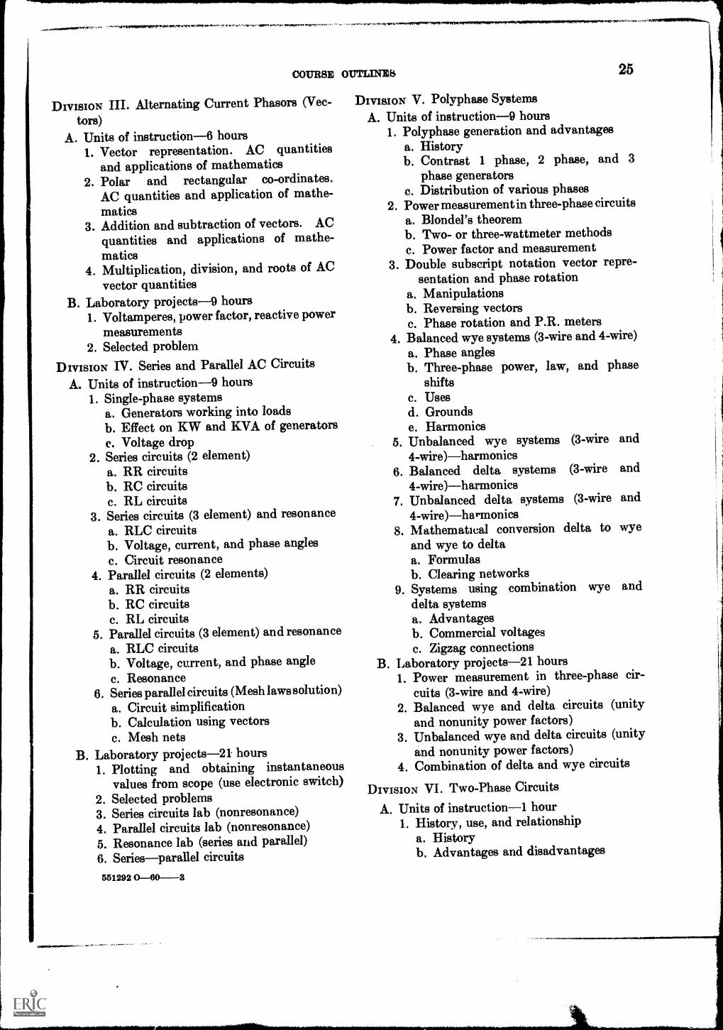
DIVISION V. Polyphase SystemsA. Units of instruction-9 hours
1. Polyphase generation and advantagesa. Historyb. Contrast 1 phase, 2 phase, and 3
phase generatorsc. Distribution of various phases
2. Power measurement in three-phase circuitsa. Blondel's theoremb. Two- or three-wattmeter methodsc. Power factor and measurement
3. Double subscript notation vector repre-sentation and phase rotation
a. Manipulationsb. Reversing vectorsc. Phase rotation and P.R. meters
4. Balanced wye systems (3-wire and 4-wire)a. Phase anglesb. Three-phase power, law, and phase
shiftsc. Usesd. Groundse. Harmonics
5. Unbalanced wye systems (3-wire and4-wire)-harmonics
6. Balanced delta systems (3-wire and4-wire)-harmonics
7. Unbalanced delta systems (3-wire and4-wire)--harmonics
8. Mathematical conversion delta to wyeand wye to deltaa. Formulasb. Clearing networks
9. Systems using combination wye anddelta systemsa. Advantagesb. Commercial voltagesc. Zigzag connections
B. Laboratory projects-21 hours1. Power measurement in three-phase cir-
cuits (3-wire and 4-wire)2. Balanced wye and delta circuits (unity
and nonunity power factors)3. Unbalanced wye and delta circuits (unity
and nonunity power factors)4. Combination of delta and wye circuits
DIVISION VI. Two-Phase Circuits
A. Units of instruction-1 hour1. History, use, and relationship
a. Historyb. Advantages and disadvantages
26 ELECTRICAL
c. Obsolete and residual2. Three-wire Edison and two-phase circuits
a. Advantages of Edison's systemb. Measurement
B. Laboratory projects-3 hours1. Two-phase measurements and vectors2. Edison 3-wire system vs 2-wire systems
measurements of voltage regulation
DIVISION VII. Integrating CircuitsA. Units of instruction-3 hours
1. Electrical response to sinusoidal wavesa. The integratorb. Influence of component valuec. Commercial uses
2. Electrical response to nonsinusoidal wavesa. Square waveb. Pulse wavec. Influence of component sizes
B. Laboratory projects-6 hours1. Graphical plot of results to waves (RC
and RL)2. Scope measurement of integrators (RC
and RL)
DIVISION VIII: Differentiating CircuitsA. Units of instruction-3 hours
1. Electrical response to sinusoidal wavesa. The differentiatorb. Influence of component valuec. Commercial uses
2. Electrical response to nonsinusoidal wavesa. Square wavesb. Pulse wavesc. Sawtooth wavesd. Influence of component values
B. Laboratory projects-6 hours1. Graphical plot of response to sinusoidal
waves
TECHNOLOGY
2. Scope measurement of nonsinusoidalwaves
DIVISION IX. Miscellaneous Alternating Circuits
A. Units of instruction-3 hours1. Methods of wave analysis
a. Scopes and graphical determinationb. Mathematical analysis
2. Electrical transientsa. Source and resultsb. Mathematical treatment
3. Effects of harmonicsa. Sourceb. Effectc. Laws of analysis
B. Laboratory projects-6 hours1. Wave analysis from scope picture and
prints2. Make up laboratory for those who need
additional experience for advanced proj-ects
Texts and References
Select one of the books on the following list fora text. Others may be used for references.ANDRES, P. G., Basic Mathematics for Engineers. New
York: John Wiley & Bons.DAWES, CHESTER L., Electrical Engineering Vol. II.
New York: McGraw-Hill Book CO.FITCH, SYLVAN and POTTER, T. L., Theory of A. C. Circuits.
Englewood Cliffs, N.J.: Prentice-Hall Book Co.MORECOCR, EARLE M., Alternating-Current Circuits.
New York: McGraw-Hill Book CO.VAN VALRENBURG, NOOGER and NEVILLE, INC., Basic Elec-
tricity, Volumes 8 & 4. Alternating Current, Resistance,Capacitance in A. C., etc. New York: John F. RiderPublisher, Inc.
IR lel, Bunko 11111graies
Hours Required
Class, 3; Laboratory, 6
Description
Introduction to the technical concepts ofelectronic components and circuits. Principlesof vacuum tubes and transistors; tuned circuitsand basic circuits for power supplies, detec-tors, amplifiers, and oscillators; radio receiv-ers; cathode-ray oscilloscopes; use of basictest devices and measuring instruments. Itis designed to follow the course DirectCurrent Circuits and Machines (ER 115) andshould be taken concurrently with TimeVarying Circuits (ER 185).
Nets: The circuit analysis in this course makes use of mathematical formsin the segues°, used In ER 164 Tecissisal MalkessatIcs II. Incrementalchanges, tor example, are explaMed by the "delta" no:Utica in the first unital the course and by calculus cemeepts In the latter units.
Major Divisions
I. Introduction to RadioII. Vacuum Tube Charac-
teristicsIII. Semiconductor Charac
teristicsIV. Power SuppliesV. Audio Amplifiers
VI. Tuning CircuitsVII. Radio-Frequency Ampli-
fiersVIII. Detector Circuits
IX. Receiving CircuitsX. Test Equipment
asshours
Labora-tory
hours
4 88 12
6 12
5 107 144 84 8
5 106 124 8
DIVISION I. Introduction to RadioA. Units of instruction-4 hours
1. History of radio communicationa. Early experimentersb. Commercial and amateur uses of radio
2. Various uses of electronicsa. Industrial controls and instrumenta-
tionb. Microwaves and radarc. Televisiond. Medical applications
3. Sound wave characteristicsa. Frequency, amplitude, and waveforms,
and the impressions of pitch, loudness,and timbre; beats
b. Characteristics of the ear; frequencyrange, loudness response
c. Speed of sound; directional behaviord. Electro-acoustic transducers; micro-
4. Simplified radio transmission and recep-tion systema. Radio wave characteristicscompari-
son of sound waves in air and electro-magnetic waves in space
b. Amplitude modulation and frequencymodulation (simple illustrations)
c. Functions of a receiverantenna, tun-ing, detection
B. Laboratory projects-8 hours1. Introductory demonstration
a. Display of "antique" radio apparatusthat may be available
b. Communications receiver demonstra-tionlistening to the signals of vari-ous types of foreign, commercial andamateur services using radio commu-nications
c. Observation of training panels thatare connected to form a typical re-ceiver. Examination of electronic com-ponents and identification of symbols.
2. Soldering, splicing, and cabling; practicein making common splices and use of ter-minals. May include soldering for printedcircuits
3. Construction of crystal receiver. Assem-bly of a kit, or construction of simple
27
28 ZIACTRICAL TZCHNOLOGY
breadboard set, wired in accordance withthe procedures given in the precedinglaboratory project, to show essential func-tions of a receiver that will be studied indetail later
4. Transmitter demonstration, using in-structional panels. May be conducted inconjunction with receiver demonstration(1c)
5. Sound and hearing demonstrationa. Electrical outputs from a microphone
and electric waves from a phonographand from an audio oscillator may bepictured on an oscilloscope at the sametime their sound is heard from a loudspeaker
b. Characteristics of the human ear maybe shown by variations of frequencyand intensity of the signal
c. Several oscillators may be used tosupply complex waveforms and showharmonic relations. The phenomenonof beats will be illustrated visually andaudibly
DIVISION II. Vacuum Tubes
A. Units of instruction-6 hours1. Diodes
a. Edison effect; electron emission andcontact potential
b. Series and parallel filament connec-tions
c. Characteristics curves; saturation,rectification and detection
2. Triodesa. Action of control gridb. Characteristic curvesc. Amplification factord. Plate resistance; transconductancee. Voltage amplification; equivalent
circuit3. Tetrodes and Pentodes
a. Effect of screen gridb. Characteristic curves; negative resist-
ancec. Effect of suppressor gridd. Beam power tubese. Characteristic curves of pentodes and
beam power tubes
B. Laboratory projects-12 hours1. Tube dissection
a. Cutting apart piece-by-piece of severaldiscarded tubes (both metal and glass)by each student
b. Freehand sketching of each element,and of the tube's internal structure
c. Reference to published tube data forsymbol and manufacturer's descriptionof each tube
2. Diode characteristicsa. Voltage-current relationships taken
with equipment connected by studentcrews and checked by instructor.With a duo-diode, curves may be com-pared for one section and both sectionsin parallel.
b. Informal report with graphs of experi-mentally obtained data, comparisonwith published characteristics, andcomments on any discrepancies
3. Triode characteristicsa. Data for transfer curves taken with
student-connected apparatusb. Informal report, as in preceding experi-
ment4. Pentode characteristics
a. Similar procedure as for triode charac-teristics. Separate sets of data shouldbe taken for sharp cut-off and for re-mote cut-off types of pentodes
b. Informal report with data presentedon curves that may be compared withthose in tube manual
5. Tube characteristics calculationsa. Calculation of amplification factor,
plate resistance, and transconductance,from the curves plotted for triode andpentode tubes
b. Informal report showing proceduresused, and evaluation of units
6. Demonstration of special tubes if timepermits, attention may be given to specialtubes, such as electron-ray indicators andpower tubes for transmitters
DIVISION III. Semiconductor CharacteristicsA. Units of instruction-6 hours
2. Semiconductor rectifiersa. Crystal diodesb. Power rectifiers
3. Transistorsa. Point-contact transistorsb. Junction transistorsc. Transistor parametersd. Power transistors
B. Laboratory projects-12 hours1. Semiconductor diode characteristics
a. Measurements for plotting forwardand reserve voltage-current relations
b. Informal report2. Characteristics of junction transistors
and surface-barrier transistorsa. Examination of effects of changing
operating voltages and currentsb. Informal report
3. Common-base amplifier characteristicsa. Gain and frequency response measure-
mentsb. Biasing methodsc. Informal report
4. Common-emitter amplifier characteristics.Procedure similar to experiment 3, above
5. Bias and stabilizationMeasurements in circuits with fixed biasand with self bias
6. Supplement. If time allows, basic tran-sistor receiver circuits may be connected,serving as an introduction to details thatwill be studied in advanced courses
DIVISION IV. Power Supplies
A. Units of instruction-5 hours1. Rectifier circuits
a. Half-wave and full-wave rectificationb. Bridge rectifiersc. Metallic-oxide rectifiersd. Peak inverse voltage
2. Voltage multipliers; transformerless powersupplies
B. Laboratory projects-10 hours1. Transformer familiarization
a. Examination of new or used powertransformers each student shouldcheck several units
b. Ohmmeter measurements for lead iden-tification
c. Voltage measurement of windings.Reduced voltage may be applied tothe primary as a safety precaution
d. Informal report showing results, withreference to standard transformer colorcoding
2. Demonstration of typical power supply,with student reports of observationsa. Waveforms at various pointsb. Output voltages and ripple with var-
ious filtersc. Measurement of regulation with var-
ious filtersd. Comparison of full-wave and half-wave
rectificatione. Correction of faults in power suppliesf. Informal reports
3. Voltage regulator tubes '
a. Connection of voltage regulator tubecircuit
b. Collection of data for graphically show-ing regulator action for conditions forchanging line voltage and for changingvalues of load
c. Compare voltagecurrent curves of56-51 and B2
d. Informal report4. Voltage divider design
a. Problem in figuring resistance andwattage ratings for a divider supplyingseveral loads with different voltagesand currents. Check of computationsby measurements on the actual circuit
b. Informal report
30 ZLICTRICAL
5. Vibrators and dynamotor'a. Examination and testing of a vibrator
power supply, such as found in carradios
b. Examination of dynamotor, generator,or motor, to note construction featuresof rotating machines
c. Informal reportDIVISION V. Audio Amplifiers
A. Units of instruction-7 hours1. Amplifier classification
a. Classification by usevoltage andpower amplifiers
b. Classification by biasClass A, ClassB, Class AB, and Class C
c. Classification by frequency response:audio, intermediate, radio, video andbroad band
2. Distortion in amplifiersa. Frequency distortionb. Phase distortionc. Amplitude distortion
8. Automatic volume controla. Supercontrol tubesb. Delayed control
B. Laboratory projects-10 hours1. Diode detector
a. Waveforms of detector in trainingequipment when fed with modulatedsignal generator
b. Informal report of detector action withvarious values of load
2. Superheterodyne constructionThis project continues through DivisionIX, and furnishes the receiver to whichtest equipment procedures are applied inDivision X. The receiver may be a kit,or may be a typical superheterodyneassembled with separately obtained parts.Chassis construction should be used.Laboratory power supply units may beutilized, but a self-contained power supplyis preferable. Circuit wiring should beginwith the power supply and the outputstage, working back to the antennaterminals. Students should have a checklist for testing their work themselvesbefore the instructor is asked to locateany errors. Demonstrations of typicalcircuits for a superheterodyne, usinglaboratory training aids, may be given bythe instructor at appropriate stages ofstudent progress.
82 ELECTRICAL
DIVISION IX. Receiving CircuitsA. Unita of instruction-6 hours
a. Frequency conversionlocal oscillator,conversion gain
b. Converter circuitspentagrid tubesc. Intermediate-frequency character-
isticschoice of value, image fre-quency, tuning ratio, spurious responses
d. Receiver alignmenttrimmers andpadders, signal generator connections,output indicators
B. Laboratory projects-12 hoursContinuation of receiver construction de-scribed in Division VIII
DIVISION X. Test EquipmentA. Units of instruction-4 hours
1. Measuring instrumentsa. Multimeters for measuring resistance,
voltage, and currentb. Output metersc. Effect of meter loadingd. Vacuum tube voltmeterse. Circuits requiring high-impedance
meters2. Cathode-ray-oscilloscope
a. Principle of operationb. Interpretation of patternsc. Uses in electronic circuit testing
3. Miscellaneous equipmenta. Signal generatorsb. Sweep oscillatorsc. Tube testersd. Capacitor checkerse. Signal tracers
B. Laboratory projects-12 hours1. Testing of tubes and components, using
test equipment studies. Units with mark-ings removed may be used for practice,
TECHNOLOGY
and variations from color code markingsmay be noted
2. Operation of oscilloscopeUse of panel controls. Observation ofsignal waveforms and Lissajous figures
3. Application of test instruments to adjust-ment and troubleshooting of superhetero-dyne project
Texts and References
Select a text from one of the following books.Others may be used as references.
Ev Earn, W. L., ed., Fundamentals of Radio and Elec-tronics. Englewood Cliffs, N.J.: Prentice-Hall BookCo.
SHEING OLD, ABRAHAM S., Fundamentals of Radio Commu-nication. New York: D. Van Nostrand Co., Inc.
SHRADER, R., Electronic Communication. New York:McGraw-Hill Book Co.
SLURZBERO, M. and OBTERHELD, W., Essentials of Radio.New York: McGraw-Hill Book Co.
For transistor study, a supplementary textshould be used with one of the above texts, suchas the following:American Radio Relay League, The Radio Amateur's
Handbook (latest edition); West Hartford, Conn.:American Radio Relay League, Inc.
DE FRANCE, J., Electron Tubes and Semiconductors.Englewood Cliffs, N.J.: Prentice-Hall Book Co.
EVANS, W. H. ed., Experiments in Electronics. Engle-wood Cliffs, N.J.: Prentice-Hall Book Co.
RIVER, M. S., Transistors in Radio, Television, and Elec-tronics. New York: McGraw-Hill Book Co.
LANG FORD-SMITH, F., Radiotron Designer's Handbook.Harrison, N.J.: Radio Corp. of America.
RIDDLE, R. L. and RUMENBATT, M. P., Transistor Physicsand Circuits. Englewood Cliffs, N.J.: Prentice-HallBook Co.
RIDER, J. F. and UBLAN, S. D., Encyclopedia on Cathode-Ray Oscilloscopes and Their Uses. New York: JohnF. Rider, Inc.
TURNER, R. P., Basic Electronic Test Instruments. NewYork: Rinehart Books, Inc.
ZBAR, P. B. and SCHILDKRAUT, S., Basic Radio and Radio-Receiver Servicing. New York: McGraw-Hill Book Co.
0 111, Shop Prams*.
Hours Required
Class, 1; Laboratory, 2
Description
Course is designed to help the individualstudent develop information in the use ofhand tools, machine tools, equipment, andvarious types of materials which he willencounter in his work as a technician.Laboratory exercises are designed to intro-duce students to tools, materials, and equip-ment with which they are unfamiliar ratherthan to give students opportunity to developproficiency only in one area. Shop safety isstressed.
Major DivisionsLaboratory
hours
I. Shop Details 3
II. Shop Organization 3
III. Bench Work 15IV. Machine Shop Tool, Equipment, and
Exercises 18
V. Miscellaneous Materials 9
DIVISION I. Shop Details-3 hoursA. Details from drafting room
1. Pencil sketches2. Blueprints3. Other
B. Templates and patterns1. Paper2. Wood3. Metal4. Plastic
DIVISION II. Shop Organization-3 hoursA. Work ordersB. Lists
1. Bill of material2. Shipping3. Inventory
C. Time study1. Cards2. Time and motion3. Waste and salvage
DIVISION III. Bench Work-15 hoursA. Layout using scale, square, dividers, pro-
tractor, and scriberB. Filing, polishing, and scraping
1. Types of files, chisels, and scrapers2. Use and care
C. Hacksawing1. Types of saws2. Mounting of blade3. Techniques in use
D. Drilling1. Hand drills2. Small power drills-uses
E. Threading-internal and external1. Types of taps2. Size of tap to size of drill3. Types of threads
a. Use of diesb. Threading pipe and conduit
F. Exercises in the use of1. Pliers2. Wrenches-open, closed, adjustable3. Clamps, vises4. Files5. Screwdrivers, punches, pry bars, etc.6. Micrometer, vernier, gauge, protractor,
trammel, scale, and rule7. Hacksaws8. Other
DIVISION IV. Machine Shop Tool, Equipment,and Exercises-18 hoursA. Lathe
1. Exercises in centering, facing, adjustingcenters, etc.
2. Turning and facing work held on man-drels; arbors
3. Measuring with micrometers4. Taper turning and boring
33
34 ELECTRICAL
B. Drill press1. Rough drilling2. Types of drills3. Cutting speed and feeding
C. Milling machine1. Selection of cutters2. Direction of feed3. Squaring
D. Forming and shaping metal and plastic1. Sheet metal
a. Types of sheet metals and their usesb. Exercises in design, layout and con-
struction of geometric forms used ininstrument chassis, raceways, andjunction boxes such as:(1) Square(2) Octagon(3) Hexagon(4) Pentagon(5) Ellipse
c. Exercises in the use of sheet metaltools and materials such as:(1) Shears(2) Folding, forming and shaping
equipment and machines(3) Bench machines and stakes(4) Groover, rivet sets, knock-out sets,
spot welder, nibbler, gas and elec-tric soldering equipment, metalscrews, etc.
2. Plasticsa. Types of plastics and usesb. Forming, shaping, and drillingc. Casting and moldingd. Fasteners
(1) Special rivets, screws, and bolts(2) Joining plastics to plastics; plastic
to metal3. Heavy-gauge metals
a. Hand forging and heat treatingb. Presses, hydraulic and handc. Castingd. Shaper and planere. Welding, gas and electric
4. Metal fastenersa. Types of rivets and usesb. Types of bolts, nuts and screws and
usesc. Types of holders, wire, pipe
(1) Insulated staples
TECHNOLOGY
(2) Insulated and nonineulated wireand pipe straps
(3) Plastic, wood and fiber damps andseparators
(4) OtherDryisIoN V. Miscellaneous Materials-9 hours
A. Wire1. Wire sizes, types, and uses
a. Types of connectorsb. Soldering and splicingc. Junction boxesd. Raceways and panels
B. Conduit1. Thinwall
a. Threadless connectorsb. Use of hickey, other bendersc. Cutting
2. Rigida. Types of connections and fittingsb. Cutting, threading, reaming and bend-
ingc. Uses
C. Insulating materialsD. Wood, wood fiber, hard rubber, and mason-
iteStudents should complete one or two projectsapplying as many of the machines, tools, andprocesses as time will permit
Texts and References
Select one of the following as a text. Othersmay be considered as possible reference books.
AUSTIN, JOHN B., Electric Arc Welding. Chicago: Ameri-can Technical Society.
BARICH, DEWEY F. and SMITH, L. C., Metal Work forIndustrial Arts Shops. Chicago: American TechnicalSociety.
BRUCE, LEROY FOWLER, Sheet Metal Shop Practice.Chicago: American Technical Society.
CARROLL, JOHN M., Mechanical Design for ElectronicsProduction. New York: McGraw-Hill Book Co.
DuBois, J. H. and PRIBBLE, W. I., Plastics, Mold Engineer-ing. Chicago: American Technical Society.
FRANKEL, JACOB PORTER, Principles of the Properties ofMaterials. New York: McGraw-Hill Book CO.
FEIRER, JOHN L., General Metals. (second edition)New York: McGraw-Hill Book CO.
GRONEMAN, CHRIS H., Mastics Made Practical. Chicago:Bruce Publishing Co.
COURSE OUTLINES
KNOBLAUGH, RALPH R., Modelmaking for IndustrialDesign. New York: McGraw-Hill Book Co.
MIIIRSIRRAU, SAMUEL FOSTER, Revised by Reen, Calvin G.
and Holderman, Kenneth L., Materials of Industry.Fourth Ed., New York: McGraw-Hill Book Co.
PORTIR, MORGAN H., Oxyacetylene Welding. Chicago:American Technical Society.
TURNER, WILLIAM P. and OWEN, HALSEY F., Machine-Tool Work. Purdue University, second edition.
VAN DORRN, HAROLD, A Practical Guide to ProductDesign and Development. New York: McGraw -HillBook Co.
0 161, Technical Report Writing
Hours Required
Class, 1; Laboratory, 0
Description
Techniques of collecting and presentingscientific data. Informal reports and formalreports; special types of technical papers.Forms and procedures for technical reportsare studied and a pattern is established forall formal reports to be submitted in thisand other courses. Prerequisite: G 133 Com-munication Skills.
Major DivisionsClass hours
I. The Scientific Method 4II. Techniques of Exposition 6
HI. The Report Form 7
DIVISION I. The Scientific Method-4 hours1. Meaning of the method
a. Cumulative natureb. Complexity of investigation
2. Characteristics of the scientific methoda. Reliance on observationb. The experimental processc. Objectivity
3. Essentials of scientific stylea. Clarity and precisionb. Conciseness and directness
4. The problem concepta. Types of problemsb. Setting up a problem
DIVISION II. The Techniques of Exposition-6hours
1. Definitionsa. The formal definitionb. The operational definitionc. The informal definition
2. The expository paragrapha. Lengthb. Structure
36
3. 72-ogression. Maintaining unity, coher-ence, and emphasis
4. Elements of stylea. Sentence structure
(1) Relation of ideas(2) Faulty references: pronouns and
modifiers(3) Balance and parallelism(4) Revision
b. Style problems(1) Shoptalk and jargon(2) Achieving readability
5. Analysis of examplesDIVISION III. The Report Form-7 hours
1. Characteristics of the report2. Report functions3. Informal reports
a. Short-form reports(1) Memorandum reports(2) Business letter reports(3) Outline reports
4. The formal reporta. Arrangement
(1) Cover and title pages(2) Table of contents(3) Summary of abstracts(4) Body of the report(5) Bibliography and appendix(6) Graphs and drawings
b. Preparation(1) Collecting, selecting, and arranging
material(2) Writing and revising the report
5. Special types of papersa. The abstractb. Process explanationsc. The case historyd. The book review
Texts and References
Select one of the following as a text. Othersmay be considered as possible reference books.
BUCKLE, M.D. and Hour, K. W., Reports for Science andIndustry. New York: Henry Holt & Co.
COURSE OUTLINES
CROUCH, WILLIAM G. and ZETLER, ROBERT L., A Guide to
Technical Writing. New York: Ronald Press.
GAUM, CARL G., GRAVES, HAROLD F., and HOFFMAN,
LYNE S. S., Report Writing. Englewood Cliffs, N.J.:
Prentice-Hall.
GUNNING, ROBERT, The Technique of Clear Writing.York: McGraw-Hill Book Co.
New
HICKS, T. G., Successful Technical Writing. New York:McGraw-Hill Book Co.
37
PHILCO TECHNOLOGICAL CANTEr, Technical Writing Guide,Philadelphia 32, Pa.: The Center, Department 259.
RHODES, FRED, and JOHNSON, HERBERT F., TechnicalReport Writing. New York: McGraw-Hill Book CO.
SANTMYERS, SELBY S., Practical Report Writing. Scranton,Pa.: International Textbook CO.
SOUTHER, JAMES W., Technical Report Writing. NewYork: John Wiley & Sons, Inc.
ULMAN, JOSEPH N., Jr., and Gould), J. R., TechnicalReporting. New York: Henry Holt & Co.
162, Graphic Analysis
Hours Required
Class, 1; Laboratory, 3
Description
Graphic representation and graphic analysis.Layout methods used in pattern and templatework. Graphs, charts, and plots with anintroduction to descriptive geometry andgraphic calculus.
Major Divisions
Classhours
Labora-tory
hoursI. Symbol Drawings 2 6
II. Sheet Metal Layouts_ _ _ 1 3III. Drawings for Machine
B. Laboratory projects-6 hoursPreparation of graphs showing differentia-tion and integration of various curves
TICEINOLOGY
Texts and References
Select one of the following as a text. Othersmay be considered as possible reference books.
BISHOP, CoLVIN C., Electric Drafting and Design. NewYork: McGraw-Hill Book Co.
FRENCH, T. E. & Visseck, C. J., Graphic Science. New York:McGraw-Hill Book Co.
Gimsmcks, Fmmrassicit E., MITCHZLL, ALVA, and others,Technical Drawing. New York: The Macmillan Co.
Kocrams, STANLEY E., Electrical Drafting. Scranton, Pa.:International Textbook Co.
LUZADDIR, WARREN J., Graphics for Engineers. Engle-wood Cliffs, N.J.: Prentice-Hall Book Co.
LUSADDIS, WARRZN J., P undainsntals of EngineeringDrawing. Englewood Cliffs, N.J.: Prentice-Hall BookCo.
COMM OUTL1311111: SECOND TZAR, THIRD umournut
S 104, Illagibulealaig lakratoe
Hours Required
Class, 3; Laboratory, 3
Description
Graphical and mathematical analysis offorces; laws of motion, machines, mechanicalpower, strength of material, fluid mechanics,and thermal conductivity; basic principles ofphysics. Principles directly related to thetechnician field of specialization will be cov-ered in greater detail in subsequent specializedcourses. Course work is extremely practicalin nature with the emphasis on applied prob-lems.
Major Divisions
Clanhour.
Labora-tory
hour.I. Forces 21 21
II. Motion 6 6III. Work and Power 6 8IV. Simple Machines 3 3V. Strength of Materials.. _ _ 3 3
VI. Fluids 3 3VII. Gases 3 3
VIII. Heat Elements 3 3IX. Light and Lenses 3 3
DIVISION I. Forces
A. Basic forces-6 hours1. Definitions
a. Definitionsb. Units of measurementc. Metric unitsd. Limits and safety factors
2. Acton and reactiot.a. Lawsb. Application of lawsc. Resultantsd. Vectors
4. Tension, compression, and sheara. Forces on membersb. Limits of materialsc. Elastic limits
5. Center of gravitya. Locating centersb. Forces on
Laboratory projects-6 hours1. Metric system of measurement2. Center of gravity (experimental)Resolution and composition of forces-4hours1. Parallelogram of forces
a. Graphical solutionb. Mathematicalc. Force reso.ution
2. Two or more forcesa. Two concurrent forcesb. Couplesc. Multi-force
3. Rectangular componentsa. Force resolutionb. Resultant
4. Polygon of forcesa. Resultantb. Equilibrantc. Unknown force
Laboratory projects-6 hoursForces and force resolutionConcurrent forces-3 hours1. Computation
a. Parallel forces on membersb. Nonparallel forcesc. Distributed loads
2. Equilibriuma. Conditions of equilibriumb. Computing
41
42 ZUKTRICAL
3. Resolution along axisa. Method of solutionb. Results
F. Laboratory projects-3 hoursPolygon of forces
G. Parallel forces-3 hours1. Moments
a. Law of momentsb. Application to forcesc. Application to rotation
2. Leversa. Three types of leversb. Application to forces
3. Couplea. Definitionb. Effect on rotationc. Practical problems
H. Laboratory projects-3 hoursLevers
I. Nonooncurrent forces-2 hours1. Conditions of equilibrium
a. Lawsb. Forces
2. Solution of typical force systemsa. Graphicalb. Mathematicalc. Safety factors
J. Trusses and structures-3 hours1. Shear legs
a. Forces in legsb. Free-body diagramsc. Calculations of forces
2. Cranes and derricksa. Typical unitsb. Loadsc. Stresses
3. Bridge and roof trussesa. Typical unitsb. Types of static loadsc. Solutions of forces
4. Graphic solutions of various trusses andstructures
K. Laboratory projects-3 hours1. Forces in boom cranes2. Forces in structures
DIVISION II. Motion
A. Units of instruction-6 hours1. Linear motion
a. Speed, distance, accelerationb. Free falling bodyc. Projected bodies
5. Creep and fatigueB. Laboratory projects-3 hours
Stress deformation, and strength of materials
DIVISION VI. FluidsA. Units of instruction--3 hours
1. Liquids, density, specific gravitya. Definitionb. Temperature effectsc. Measurements
2. Pressure, transmission of pressurea. Factors affectingb. Gauge and absolutec. Transmission and vessel pressure
3. Archimedes' principle and hydrometersa. Archimedes' principleb. Application to industrial use, i.e.
boats, and floatsc. Hydrometric measurement methods
4. Flow in pipes, friction loss of heada. Bernoulli's principleb. Analogy to electric systemsc. Pipe friction, including headsd. Discharge rates orifices, flow measure-
mentsB. Laboratory projects-3 hours
Archimedes' principle and hydrometers
OUTLINZ8
DIVISION VII. GasesA. Units of instruction-3 hours
1. Pressure of gasesa. Measurement methodsb. Flow of gasesBernoulli's principlec. Pressure differential and gas flow
2. Gas laws and applications3. Flow of air
a. Compressorsb. Cleaning and Rater trapsc. Measuring
B. Laboratory projects- 3 hoursGas laws
DIVISION VIII. Heat ElementsA. Units of instruction-3 hours
1. Heat unitsa. B.T.U.b. Measuring B.T.U. of fuelsc. Purchasing by B.T.U.: fuels, rates, and
costs2. Expansion and contraction due to heat
a. Expansion coefficientb. Bimetalsc. Expansion joints
3. Specific heat and temperatures of mix-turesa. Specific heat of matterb. Heat of mixturesc. Heat loss
4. Heat transfera. Transfer through materialsb. Application to heat loss and air
conditioningc. Use of heat transfer constantsd. Convection, conduction, and radiatione. Diffusivity
B. Laboratory projects-3 hoursSpecific heat and heat of mixture; transferheat
DIVISION IX. Light and Lenses
A. Units of instruction-3 hours
1. Nature of lighta. Light definitions and generationb. The spectrum (ultra violet infra reds)c. The eye
2. Transmission of lighta. Transmission, reflection, and aborptionb. Velocity, frequency, and wave lengthc. Measuring
B. Laboratory projects-1 hour1. Light2. Lens3. Focal centers4. Spectrum
Texts and References
ELECTRICAL TECHNOLOGY
Select one of the following as a text. Othersmay be considered as possible reference books.BRIE, FERDINAND P. and JOHNSTON, RUSSELL E., Me-
chanics for Engineers. New York: McGraw-Hill BookCo.
BLACK, NEWTON HENRY, and LITTLE, ELSISZT P., Intro-ductory Course in College Physics. New York: TheMacmillan Co.
BEINEMAN, JOHN W., Mechanics. New York: McGraw-Hill Book Co.
DULL, CHARLES E., METCALF', H. CLARK, and&Loose, WILLIAM 0., Modern Physics, New York:Henry Holt & Co.
HARMS, N. C., and HEMMERLING, E. N., IntroductoryApplied Physics. New York: McGraw-Hill Book Co.
MERAIN, J. L., Mechanics Statics, Part I. New York:John Wiley & Bons.
OLIVO, C. THOMAS, and WA THS, ALAN, Basic Science,Part I, Physics. Albany, N.Y.: Delman. PublishingCo.
WEBER, R. L., WHITS, MILO, and MANNING, K. V.,Physics for Science and Engineering. New York:McGraw-Hill Book Co.
WHITS, MARSH WILLIAM, MANNING, K. V., and Win's,R. L., Practical Physics. New York: McGraw-HillBook Co.
213, Electrical Instruments and Measursznonts
Hours Required
Class, 2; Laboratory, 3
Description
The mechanics and the science of electricalmeasurements are given thorough treatmentin the course. Starting with basic indicatinginstruments and continuing through complexintegrating devices, both the operating princi-ples and the "hardware" are studied. Rangeextending devices, rectifiers, bridges, andtransformers are used in the laboratory toconstruct metering systems for typical job re-quirements. Operation, repair and calibrationof measuring instruments. Mathematicalanalysis is used throughout the course withextensive use of vector algebra and trigonom-etry. Prerequisite: ER 185.
Major DivisionsCasahours
Labora-tory
hours
I. D.C. Meters 4 6II. A.C. Indicating Meters.. _ 4 3
3. Shunts and multipliersa. Calculationsb. Temperatures and metalsc. Leads of multipliers
4. Thermal metersa. Hot wire typeb. Junction typec. Thermal converters
5. Ohmmeters and meggersa.. Series ohmmetersb. Shunt ohmmeterc. Meggerd. Meggohmer
B. Laboratory projects-6 hoursGalvanometer movementShunts and Mul-tipliers
DIVISION II. A.C. Indicating MetersA. Units of instruction-4 hours
1. Rectifier metersa. Rectifier principle and typesb. Linear scale meters
2. Iron vanea. Inclined coilb. Westonc. Uses and limitations
3. Dynamometera. Volt metersb. Watt meters (1-phase and 3-phase)c. Graphic meters
B. Laboratory projects-3 hours1. ConstructionSketches and explanations2. Calibration of meters3. Resealing of meters
DIVISION III. Miscellaneous Indicating Meters
A. Units of instruction-2 hours1. Frequency meters
a. Frahm Reedb. Resonance circuitc. Resonance
45
46 trzerRicAL
2. Power factor metersa. Tuma, one-phaseb. Three-phase tuma
3. Synochronoscope-GE iron vane4. Phase sequence meters
a. Rotating vaneb. Light type
5. Meter phase switchinga. Voltmeter switchingb. Ammeter switching
B. Laboratory projects-3 hours1. Meter sketching2. Meter switching
DIVISION IV. Integrating MetersA. Units of instruction-3 hours
1. KWH parts and metering termsa. Metering definitionsb. Meter constants and multipliersc. Indentification of KWH parts
2. Principles of operationa. Rotating fieldb. Disc speedsc. Coil variations
3. Multiple element metersa. Wyeb. Deltac. Transformer type
4. Meter cleaning, inspection, and mechani-cal partsa. Type cleanerb. Inspection methodsc. Adjustments
5. Three methods of calibrationa. Portable standard, referenceb. Counting circuitsc. Stroboscopic method
6. KVA meteringa. Circuit using KWHb. Westinghouse KVA. meter
7. Reactive meteringa. Purposeb. Circuit using KWH
B. Laboratory projects-12 hours1. Sketching meter components2. Checking meter constants3. Meter calibration4. Meter connection of KVAR and KVA
DIVISION V. Instrument Transformer MeteringA. Units of instruction-4 hours
1. The potential instrument transformera. Types
TECHNOLOGY
b. Ratingsc. Errorsd. Compensations
2. The current instrument transformera. Proper meter multipliers due to trans-
formerb. Compensation for transformer errorsc. Typesd. Ratingse. Errorsf. Compensation
3. The circuitsa. Potential to boardb. Current to board
4. The metering constantsa. Proper meter multiplier due to trans-
formerb. Compensation for transformer errors
B. Laboratory projects-8 hours1. Make a transformer metering connection2. Visit meter laboratory
DIVISION VI. Special MeteringA. Units of instruction-4 hours
1. Thermal meteringa. Voltb. Amperesc. Kilowatt
2. Demand meteringa. Types and applicationb. Constants
3. Time controlled metering4. Totalizing meters5. Carrier current
B. Laboratory projects-6 hours1. Circuit connection and constants of
thermal demands2. Construction of a small carrier current
controlled device
DIVISION VII. Laboratory MeasurementsA. Units of instruction-9 hours
1. Loop testa. Murray Loopb. Varley Loop
2. Bridge measurementsa. A.C.
(1) Impedance(2) Capacitance
b. D.C.(1) Slide wire(2) Dial bridge(3) Double bridge
COURSE
3. Oscillographs (not scopes)a. Visual (rotating mirror)b. Photographicc. Direct recording
4. Potentiometers (including micromax)a. Voltage dividesb. Standardizationc. Recording
5. Instrument transformer teeth for errorsa. Potential transformersb. Current
B. Laboratory projects-9 hours1. Loop tests for troubled lines2. Bridge tests3. Use of oscillograph
DIVISION VIII. Commercial Kilowatt Hour Meters
A. Units of instruction-4 hours1. Duncan2. General Electric3. Sangamo4. Westinghouse
OUTLINES 47
B. Laboratory projects-6 hoursComparison and study of the design andconstruction of various commercial meters
Texts and ReferencesSelect one of the following books for a text.
Others may be used as possible references.
EDISON ELRCTRIC INSTITUTIII, Electrical Metermans Hand-book. New York: Edison Electric Institute.
DUNN, C. H., and BARKIMR, H. J., Electric MeasurementsManual. Englewood Cliffs, N. J.: Prentice-HallBook Co.
HARRIS, F. K., Electrical Measurements. New York: JohnWiley & Sons, Inc.
LAWS, FRANK A. Electrical Measurements. New York:McGraw-Hill Book Co.
MACGAHAN, PAUL, Electrical Measuring Instruments.Scranton, Pa.: International Textbook Co.
RHODZIS, T. J., Industrial Instruments for Measurementand Control. New York: McGraw-Hill Book Co.
SMITH, A. W . and WRIDIENBIECK, M. L., Electric Measure-?twat. New York: McGraw-Hill Book Co.
STOUT, MKLVILLL B., Basic Electrical Measurements.Englewood Cliffs, N. J.: Prentice-Hall Book Co.
E 215, Alternating Current Machines
Hours RequiredClass, 3; Laboratory, 6
Description
The work in this course is confined to a studyof mechanical-electrical power devices. Alter-nators, single-phase motors and three-phasemotors, transformers, voltage regulators, gen-erators, as well as the auxiliary control equip-ment necessary for these devices are studied.Laboratory work consists mainly of runningload tests on selected equipment and studyingthe characteristic behavior of these units undervarying operating conditions. Installationand maintenance requirements for alternatingcurrent power equipment are given someattention. Prerequisite: ER 185.
Major DivisionsLabora-
Class toryhours hours
I. Polyphase Systems Re-view 4 9
II. Transformers (Physical) 3 3III. Transformer Operational
Characteristics 9 16IV. Three-Phase Transform-
ers 2 8V. Special Transformers___ 7 6
VI. Alternators 12 12VII. Three-Phase Motors.. _ _ 7 15
3. Repulsion motorsa. Mechanical constructionb. Electrical theoryc. Response curves, cost, and used. Repulsion startinduction rune. Repulsion startrepulsion run
4. Universal motorsa. Theoryb. Curves and uses
B. Laboratory projects: single phase motors-15 hours1. Starting efficiency2. Phase angles or start3. Heat run4. Speed torque curves5. Phase changer
COURSE OUTLINES
DIVISION XI. Minute MotorsA. Units of Instruction-1 hour
1. Shaded pole motora. Theory of operationb. Costs and use
2. Make and break motorsa. Theory of operationb. Cost and use
3. Telechron clock motorsa. Theory of operationb. Cost and use
4. Single-phase synchronous(reluctance) motorsthe-ory of operation
B. Laboratory projects-12 hours1. Minute motorefficiency tests and opera-
tion2. Make-up-6 hours
51
Texts and ReferencesSelect one of the following books for a text.
Others may be used as possible references.BAILEY, B. F., and GAULT, J. S., Alternating Current
Machinery. New York: McGraw-Hill Book CO.BLUME, L. F., Transformer Engineering. New York:
John Wiley & Sons.DAWES, CHESTER L., A Course in Electrical Engineering
Vol. II. New York: McGraw-Hill Book CO.KRAENHENBUEHL, JOHN 0., and FAUCETT, MAX A.,
Circuits and Machines in Electrical Engineering.New York: John Wiley & Sons.
REED, HENRY T., and CORCORAN, GEORGE F., ElectricalEngineering Experiments. New York: John Wiley &Sons.
SEALEY, W. C., Transformers, Theory and Construction.Scranton, Pa.: International Textbook CO.
SISKIND, CHARLES S., Induction Motors. New York:McGraw-Hill Book CO.
VEINOTT, CYRIL G., Fractional Horsepower Electric Motors.New York: McGraw-Hill Book CO.
WOOD, W. S., Theory of Electric Machines. London:Butterworth Scientific.
E 272, Electrical Installation Planning
Hours Required
Class, 2; Laboratory, 0
Description
Methods and materials used in electrical in-stallations and problems encountered inelectrical construction work. Wiring ma-terials including those in the National ElectricCode.Note: Although no laboratory is shown forthis instruction, it would be desirable wherepossible to inspect selected examples of in-dustrial installations.
Major Divisions
Class hoursI. General Principles of Electrical Wiring_ 18
II. Industrial Wiring Requirements 16
DIVISION I. General Principles of Electrical Wir-ing-18 hours
1. Codes and laws governing electric instal-lationsa. Local codes and lawsb. National Electric Codec. National Safety Code
2. Materials, fittings and devices3. Circuits
a. Power circuitsb. Switch circuitsc. Signal circuits
4. Over-current protection5. Conductors
a. Typesb. Sizesc. Computing carrying capacityd. Computing voltage drop
6. Theory and practices of grounding7. Wiring methods
a. Open wiringb. Cable wiring
52
c. Wiring in racewaysd. Surface wiring
8. Branch circuitsa. Computing number and size requiredb. Over-current protectionc. Individual circuits
The course includes the basic principles ofchemistry and application of these principles inindustrial processes. Sources of raw materi-als useful in industry and the modificationof these materials through changes in chem-ical and physical properties are considered.
Major Divisions
I. Fundamental Princi-
Classhours
Labora-tory
hours
ples 1 6II. The Atom: Its Struc-
ture and Behavior 2 3III. Oxygen: Speed of Re-
action 1 3IV. Foimulas and Equa-
tions 1 0V. Hydrogen 1 3
VI. Valence 2VII. Classification and No-
menclature of Com-pounds 2 3
VIII. Ionization 2 0IX. Electrochemistry 2 6X. Acids, Bases, and Salts,
Hydrogen Ion Con-centration 2 3
XI. Kinetic Molecular The-ory and States ofMatter 3 3
XII. Water and Solutions_ _ 1 0XIII. Metallurgy. Oxida-
tion and Reduction_ 3 6XIV. Metals: Iron, Cobalt,
and Nickel 1
XV. Carbon and Its Oxides._ 2 3
54
Classhours
XVI. Organic Compounds :Hydrocarbons and
Labora-toryhours
Their Derivatives___ 3 6XVII. Organic Compounds :
Polymers 3 6XVIII. Review 2 0
DIVISION I. Fundamental PrinciplesA. Units of instruction-1 hour
1. Definitions and descriptions of: matter,energy, chemical and physical changes,properties, density, compounds, elements,metals, nonmetals, atoms, molecules
2. Law of Definite Proportion and Law ofConservation of Matter and Energy
3. The metric system of measurementB. Laboratory projects-6 hours
1. Practice in measuring various objectswith metric rules, graduates, balances,and scales
2. Density of water by use of Harvard tripscale and graduated cylinder
3. Written laboratory reportDivisioN II. The Atom: Its Structure and Be-
haviorA. Units of instruction-2 hours
1. The Bohr concept of the atom with anevaluation of its uses and limitation.Emphasis on the role of the outer elec-Irons and some explanation of radioactivity and nuclear energy
2. Electrovalent and covalent compounds3. Valence: Molecular weights and formula
weightsB. Laboratory projects-3 hours
1. Use of triple beam balances and pipettesin determining density. Use of hydrom-eters with different scales, i.e., specificgravity, Baume, API, etc.
2. Errors and percentage errors. Identifica-tion of metals from density determination
3. Written laboratory report
COURSE
DIVISION III. Oxygen: Speed of ReactionA. Units of instruction-1 hour
1. Properties, preparation, sources, and uses2. Acid anhydrides and basic anhydrides3. Combustion as oxidation4. Factors affecting rate of combustion
B. Laboratory projects-3 hours1. Stability of oxygen compounds, properties
of oxygen and oxides2. Written report including equations for all
reactions
DIVISION IV. Formulas and EquationsA. Units of instruction-1 hour
1. Discussion and drill on writing formulasand equations
2. Various meanings of formulas and inter-pretation of equations
3. Percentage composition
DIVISION V. HydrogenA. Units of instruction-1 hour
1. Sources, properties, production, and usesof hydrogen
2. Displacement and displacement series3. Periodic table
a. Classification of elementsb. Physical and chemical behavior of
elements as predicted from tableB. Laboratory projects-3 hours
1. Examination of a great variety of metalsand nonmetals for physical and chemicalproperties including, where practical,color, lustre, hardness, ductility, density,conductivities, and state at room tem-perature.
2. Determine acidity or basicity of watersolutions of oxides of various elements.Written report
DIVISION VI. ValenceA. Units of instruction-2 hours
1. Relation of valence to atomic structure2. Use of valence in writing formulas3. Experimental determination of valence4. Electrovalence, covalence, coordinate val-
ence. Drill and memorization of valencesand formulas.
DIVISION VII. Classification and Nomenclature ofCompoundsA. Units of instruction-2 hours
1. Definitions and properties of acid, salts,and oxides
OUTLINES 55
2. Type reactions of acids, bases, salts, andoxides
3. Naming of acids, bases, salts, and oxidesB. Laboratory projects-3 hours
1. Measure conductivity of solution of acids,bases, and salts of same concentration
2. Repeat at other concentrations includingdry or 100 percent concentrations and onsome covalent compounds including water
3. Determine conductivity of one or twononaqueous salt or acid solutions
4. Determine effect on blue and red litmusand wide range pH paper
5. Action on dried zinc, selected acids andbases. Taste and feel of dilute acid, base,and salt solutions. Written report
DIVISION VIII. IonizationA. Units of instruction-2 hours
1. Conduction in solution of acids, bases,salts and molten salts
2. Colligative properties3. The Arrhenius ionization theory as ex-
planation4. Debye-Huckel modifications5. Degrees of ionizations6. Neutralization and other reactions in
aqueous solutionsDIVISION IX. Electrochemistry
A. Units of instruction-2 hours1. Electrolysis2. Faraday's laws3. Voltaic cells4. Electrode potentials and relation to dis-
B. Laboratory projects-6 hours1. Electrolysis of water-copper electrodes2. Electrolysis of cupric sulfate solution with
silver anode and iron cathode and withcarbon electrodes
3. Electrolysis of colorless potassium iodidesolution containing phenolphthalein withcarbon electrodes
4. Chromium, nickel, and silver plating5. Written report
DIVISION X. Acids, Bases, and Salts, HydrogenIon ConcentrationA. Units of instruction-2 hours
1. Hydrogen ion concentration
56 ELECTRICAL TECHNOLOGY
2. Ionization of acids and importance ofwater
3. Polyprotic acids4. Ionization of bases5. Strength of acids, and bases: molalities
and normalities6. Hydrogen ion concentration and pH scale
of measurementB. Laboratory projects-3 hours
1. Determine pH of a number of acid, base,salt solutions and a few natural productssuch as saliva, vinegar, detergent solu-tions, etc., by use of short range indicatorpapers and by liquid indicator standards
2. Demonstrate use of glass electrode pHmeter
3. Calculate hydrogen ion concentration andhydroxyl ion concentration of selectedsolutions from pH determination
4. Written reportDIVISION XI. Kinetic Molecular Theory and
2. Kinetic theory applied to gases3. Liquefaction, critical points4. Liquid states: evaporation, condensation,
heat of vaporization and condensation,boiling point, surface tension, viscosity,distillation
5. Kinetic theory applied to liquids6. Solid state: freezing, melting, sublimation,
heat of fusion7. Crystalline and amorphous state8. Kinetic theory applied to solids
B. Laboratory projects-3 hours1. Galvanic couple and effect on rate of
dissolving of acid on metal2. Make and observe simple dry cell and
lead storage battery3. Determination of equivalent weight of
copper by application of Faraday's law4. Examine in detail an electric refrigerator
identifying important mechanical parts5. Use of tables in determination of suitable
refrigerant6. Interpretation of temperature pressure
curves7. Written report
DIVISION XII. Water and SolutionsA. Units of instruction-1 hour
1. Chemical properties of water hydrates2. Solutions: types and classification3. Dissolving, saturation, unsaturation,
supersaturation4. Temperature effects on dissolving5. Solubilities6. Concentrations7. Distillation and distillation curves of
volatile mixtures8. Freezing points of so:utions
DIVISION XIII. Metallurgy: Oxidation and Re-ductionA. Units of instruction-3 hours
1. Bonding forces, physical properties2. Alloys, simple phase diagrams3. Occurrence4. Minerals and ores, metallurgy5. Chemical properties of metals6. Metal oxides and hydroxides7. Electron definition of oxidation and
reductionB. Laboratory projects-6 hours
1. Laboratory on ore concentration by flota-tion
2. Production of mercury by roasting cinna-bar and heating oxide
3. Roasting and reduction of galena4. Thermal decomposition of CuCO3 and re-
duction of CuO5. Essential parts and design of Bunsen
burners, gas stove, welding torch6. Determination of available temperatures,
and how these are produced by changingactivity and concentration of fuels andsupporters of combustion used
7. Products of combustion8. Examination of types of flames produced
under various conditions9. Written report
DIVISION XIV. Metals: Iron, Cobalt, and NickelA. Units of instruction-1 hour
1. Occurrence, metallurgy, properties of iron2. Steel production and properties
DIVISION XV. Carbon and Its OxidesA. Units of instruction-2 hours
2. Fats, sugars, proteins, cellulose, rayon,dacron, nylon, natural and artificialrubbers and plastics
551292 0-60-5
57
B. Laboratory projects-6 hours1. Separation of commercial lacquers into
components by steam distillation2. Examination of water soluble solvent
through a boiling point curve3. Examination of water insoluble solvent
through a boiling point curve4. Make lacquer from ingredients provided
and use on test panel5. Make test panels of a sample of commer-
cial lacquer6. Test both panels for film hardness and
resistance to various solvents7. Written report
DIVISION XVIII. Review-2 hours
Texts and References
Select one of the following as a text. Othersmay be considered as possible reference books.BADGER, WALTER T. and BANCHERO, JULIUS T., Introduc-
tion to Chemical Engineering. New York: McGraw-,Hill Book CO.
BENSON, SIDNEY W., Chemical Calculations. New York:John Wiley & Sons.
HOLMES, HENRY N., Introductory College Chemistry. NewYork: The Macmillan CO,
LEIGHTON, ROBERT B., Chemistry of Engineering Materials.New York: McGraw-Hill Book CO.
PRUTTON, CARL, and MARON, SAMUEL H., FundamentalPrinciples of Physical Chemistry. New York: TheMacmillan CO,
SORUM, CLARENCE H., How To Solve General ChemistryProblems, second edition. Englewood Cliffs, N.J.:Prentice-Hall Book Co.
SORUM, CLARENCE H., Fundamentals of General Chemistry.Englewood Cliffs, N.J.: Prentice-Hall Book CO.
WALTON, H. F., Elementary Quantitative Analyses. Engle-wood Cliffs, N.J.: Prentice-Hall Book Co.
COURSE OUTLMES: SECOND YEAR, FOURTH SEMESTER
E 264, Industrial Electronics
Hours Required
Class, 3; Laboratory, 3
Description
Application of electronics to the control ofpower equipment. The basic circuits, con-trol elements and hardware of controls areused to acquaint the student with circuit ap-plications. The emphasis is on circuit theoryand operation, limiting variables, and re-sponse characteristics of the typical incias-trial control equipment.
Major Divisions
I. Feedback CircuitsII. Electronic Timers
III. Thermonic Electronics _
Classhours
336
Labora-tory
hours
333
IV. Photoelectric Cell De-vices 6 6
V. Industrial Power Con-version 3 3
VI. Electronic ControlledPower Machines 6 6
VII. Electronic Heating Sys-tem Control 3 3
VIII. Transistors 6 12IX. Servomechanisms 15 15
DIVISION I.
A. Feedback Circuits-3 Hours1. Amplifier Response curves2. Corrections with feedback3. Cathode followers
B. Laboratory-3 hoursSimplified feedback amplifiers
58
DIVISION II.
A. Electronic Timers-3 hours1. Time delay circuits2. Counting circuits3. Industrial application
B. Laboratory--3 hoursBasic timing and time delay circuits
B. Laboratory-3 hours1. Circuit tracing diathermy or similar heat
devices2. Testing operation of flame failure mock-
ups
DIVISION IV.
A. Photoelectric Cell Devices-6 hours1. Basic circuits2. Response curves of photo elements3. Photoelectric instruments and controllers4. Photo cell counting
B. Laboratory-6 hours1. Photoelectric cell response2. Photoelectric cell controlled devices
DIVISION V.
A. Industrial Power Conversion-3 hours1. The thyratron and ignition tubes2. Wave shapes and loading effects3. Phase shift control of rectifiers
B. Laboratory-3 hoursA.C. to D.C. convertors using thyratronphase shift controls
COURSE
DIVISION VI.
A. Electronic Controlled Power Machines-6hours1. Motor with fixed speedvariable speed
motor controllers2. D.C. generator exciter controller3. D.C. motor electronic controllers4. A.C. motor speed controllers5. A.C. motor reversing electronics6. Slip-ring motor controllers
B. Laboratory-6 hours1. Electronic drag cup motor controller2. Electronic control of slip-ring controllers
DIVISION VII.
A. Electronic Heating System Control-3 hours1. Basic heat sensing elements2. On-off controllers and cycling3. Inside-outside controllers
B. Laboratory-3 hoursBasic heat system controller
DIVISION VIII.
A. Transistors-6 hours1. Transistor as element in electronics2. Transistor types and characteristics3. Transistor functions in amplifiers4. The transistor amplifier5. Response curves of transistor amplifiers6. Transistor power amplifiers7. Transistors in push-pull
B. Laboratory-12 hours1. The transistor constants
OUTLINES 59
2. Design a single-stage transistor amplifier3. Assemble a single-stage transistor ampli-
fier and test4. Assemble a 3-stage transistor amplifier
DIVISION IX.
A. Servomechanisms-15 hours1. Open- and closed-circuit principles with
block diagrams2. Problems of feedback; gain, time re-
sponse, oscillations, error sensing3. Servo control of D.C. motors4. Servo control of A.C. motors5. Mechanical servo units
B. Laboratory-15 hours1. Operational test of heatingunit servo2. Operational test of D.C. motorservo
controlled
Texts and References
Select one of the following as a text. Othersmay be considered as possible reference books.ARNETT, F. A., Practical Industrial Electronics; New York:
McGraw-Hill Book Co., Inc.BENEDICT, R. RALPH, Introduction to Industrial Electronics.
Englewood Cliffs, N.J.: Prentice-Hall Book CO.COCKRELL, W. D., Industrial Electronic Control. New
York: McGraw-Hill Book CO.KLOEPPLER, ROYCE G., Industrial Electronics and Con-
trols. New York: John Wiley & Sons.Learning Electric and Electronics Experimentally. Vin-
cennes, Ind.: Scientific Book Co.
E 274, Electrical Control Circuits
Hours Required
Class, 3; Laboratory, 3
Description
The principles and applications of electricalcontrollers are covered in this course, whichserves as an introduction to automation.Devices for differentiation, integration andproportioning are studied in detail. Hard-ware and circuitry for AC and DC industrialcontrol devices including contactors, starters,speed controllers, time delays, limit switches,and pilot devices. Application in the controlof industrial equipment-motors, servo units,and motor-driven actuators. Laboratorydemonstrations and field trips are provided.Prerequisite: E 215.
Major Divisions
Classhours
Labora-tory
hoursI. Control Fundamentals _ 3 3
II. DC Acceleration andSpeed Control Meth-ods 3 3
III. DC Control Gear 3 3IV. Adjustable Voltage Con-
trollers 2 3V. Two-Series Motor Drives.. 2 3
VI. Alternating Current Con-tactors and Relays__ _ 2 3
VII. Controls for Slip-ringMotors 3 3
VIII. Squirrel Cage Controls_ 3 3IX. Single-Phase Motor Con-
trollers 3 3X. Various Controller De-
vices 3 3XI. Typical Controlled Sys-
tems 24 2160
DIVISION I. Control FundamentalsA. Units of instruction-3 hours
1. Nomenclature, symbols, and definitions2. Pilot devices3. Contactors and relays4. Time delay methods
B. Laboratory projects-3 hoursDC contactors and their operation andmechanical construction
DIVISION I.I. DC Acceleration and Speed ControlMethodsA. Units of instruction-3 hours
1. CEMF method2. Lockout contactors3. Voltage drop contactors4. Millticircuit timers5. Motor-driver timers6. Capacitor discharge method7. Face plate starters8. Drum type controllers
B. Laboratory projects-3 hoursD.C. starting methods
III. DC Control GearA. Units of instruction-3 hours
1. Resistorsa. Field discharge wire-wound Thyriteb. Sizing resistors
2. Field failure protection3. Reversing rotation4. Plugging5. Speed control by field resistors6. Decelerating relay7. Motor driven rheostats8. Amplidyne
B. Laboratory projects-3 hours1. DC Field protection2. DC Speed control
DIVISION IV. Adjustable Voltage ControllersA. Units of instruction-2 hours
1. Basic systemsingle-motor controlled2. Multiple motor controls
COURSE
3. Synchronizing motor drivesB. Laboratory projects-3 hours
Adjustable voltage speed n.ontrol of a com-pound motor
DIVISION V. Two-Series Motor Drives
A. Units of instruction-2 hours1. Basic system2. Braking3. Lowering controllers4. Transition methods5. Drum switching6. Speed-torque curves and calculations
B. Laboratory projects-3 hours1. DC starters2. Drum controllers
DIVISION VI. A.C. Contactors and Relays
A. Units of instruction-2 hours1. Shading poles and noise2. Series relays3. Overload devices
a. Magneticb. Thermal
4. Phase failure5. Phase reversal
B. Laboratory projects-3 hoursBasic AC controllers and relays
DIVISION VII. Controls for Slip-Ring Motors
A. Units of instruction-3 hours1. Timing relays operated by starting de-
vices2. Inductive time delays3. Capacitor time delays4. Series relays5. Face plate controller6. Drum controllers7. Frequency relays8. Calculations of accelerating time9. Kraemer system
A. Units of instruction-3 hours1. Auto-transformer starters
a. Compensatorb. Korndorfer
2. Resistor starters3. Part - winding starters-wye-delta starters
OUTLINES 61
4. Multiple speed controllers. Differentwindings
5. Induction generators6. Concatenation of rnotors
B. Laboratory projects-3 hours1. Induction generators2. Induction motor starters
DIVISION IX. Single-Phase Motor ControllersA. Units of instruction-3 hours
1. Capacitor motor controllers and arrange-ments of capacitors
2. Repulsion motors3. Auto-transformer controller
B. Laboratory projects-3 hoursSingle-phase motor starters and speed con-trollers
DIVISION X. Various Controller Devices
A. Units of instruction-3 hours1. Feedback systems
a. Block diagram and error systemsb. Troubles of feedback
(1) Gain(2) Oscillation
2. Basic sensing devicesa. Thermocouplesb. Tachometersc. Differential transformersd. Photoelectrice. Saturable transformers and magnetic
amplifiersf. Electronic speed regulators
B. Laboratory projects-3 hoursBasic sensing devices
DIVISION XI. Typical Controlled Systems
A. Units of instruction-24 hours1. Photoelectric controlled systems
a. Measuring devicesb. Alarm systemsc. Motored devices
2. Level controllersa. Float controllersb. Magnetic coupled controllersc. Remote controlled
3. Temperature control systemsa. Thermocouple potentiometer con-
trollersb. Contact galvanometer potentiometer
controllerc. Resistance-thermometer controller
62 ELECTRICAL
4. Electrical control of fluid flowa. Electromagnetic valves and control
methodsb. Motor driven valves and control
methodsc. Servo-motor controlled valves and
systemsd. Electronic controllers and systems
5. Electrical telemetering as a control systema. Variation of electrical quantitiesb. Null balance methodc. Electrical synchronizingd. Impulse selection
6. Electro-mechanical systema. Transducers as controllersb. Magnetic tape controllersL. Sequence switching controller
7. The amplidyne controlled systema. The amplidyne generatorb. Voltage regulation by the amplidynec. Thermotrol motor controller
B. Laboratory projects-21 hoursLaboratory projects will be determined bythe selection of systems that are availablefor study. Wherever possible it is recom-mended that field trips be taken andreported by the students.
Texts and References
Select one book from the following list for atext. Others may be used as references.
HARWOOD, P. B., Control of Electric Motors. NewYork: John Wiley dc Sons.
JONES, R. W., Electric Control Systems. New York:John Wiley dc Sons.
JAMES, H. D., and MARKLE, L. E., Controllers for ElectricMotors. New York: McGraw-Hill Book Co.
E 284, Electrical Power Systems In -Plant Distribution(With Utility Systems Option)
Hours Required
Class, 3; Laboratory, 3
Description
A study of the design, operation and technicaldetails of modern power distribution systemsincluding ger -mating equipment, transmissionlines, plant distribution, and protection de-vices. System load analysis, rates, andpower economics are studied.Note: The course outline is organized so thata choice in emphasis between utility systemsand plant distribution systems must bemade to stay within the time allotted.If the utility option is desired, the materialin Division VI, Plant Distribution should beeliminated or only briefly covered. If thedesire is concentration on Plant Distribution,Division VII, VIII, and IX should be elimi-nated or given only very brief survey cov-erage.
Major DivisionsLabora-
Class toryhours hours
I. Power PlantsII. Plant Operation
III. Switch GearIV. Circuit BreakersV. Short Circuit Currents
VI. Plant DistributionVII. Transmission Lines _ _ _
VIII. Transmission Line Cal-culations
IX. Distribution SystemsX. Lightning Protection
XI. RelaysXII. Economics of Electric
Service
3464592
642
12
4
3
DivirsioN I. Power PlantsA. Units of instruction-3 hours
4. Gas turbine plantsa. Mechanical constructionb. Economic usesc. As topping unitsd. Locomotive prime movers
5. Atomic plantsa. Theory of operationb. Types of plantsc. Future developments
DIVISION II. Plant OperationA. Units of Instruction-4 hours
1. Load graphsa. Types of graphs
(1) Daily(2) Weekly(3) Monthly(4) Yearly
b. Data and use of graphs(1) Demand(2) Plant factors(3) Load factors(4) Utilization factors
63
64 ELECTRICAL
2. D.C. generators as excitersa. Excitation circuitsb. Common excitersc. Unit excitersd. Emergency units
(1) Steam driven(2) Gas driven(3) Batteries
3. Common voltage regulatorsa. Silverstatb. Rocking drumc. Diactord. Amplidynee. Electronic
4. Plant electrical layouts and circuitbreaker systemsa. Single bussingle circuit breakerb. Double bussingle circuit breakerc. Double busdouble circuit breakerd. Ring bus systeme. Low voltage and high voltage bus
DIVISION III. Switch GearA. Units of instruction-6 hours
4. Sample problems on short circuitinga. Single linesb. One generatorl-linec. System shorts
DIVISION VI. Plant DistributionA. Units of Instruction-9 hours
1. Plant loads and lightinga. Plant load graphsb. Grounding practicesc. Calculations of load centerd. Motor and lighting power centerse. Circuit breakers, fuses, and their co-
ordination to plant loads1. Service entrances, conduit, channels,
ducts, etc.g. Voltage drops, their calculations using
graphsh. Capacitor switching
2. Plant electrical maintenancea. Plant electrical safetyb. Voltage regulationc. Capacitor installation and calculationsd. Electrical load surveyse. Plant electrical inspection
B. Laboratory projects-3 hours1. Load center calculations and plant load
calculations2. Various types of power entrance designs3. Voltage drop calculations, capacitor
calculations and time control plan
DIVISION VII. Transmission LinesA. Units of instruction-2 hours
1. Location limitationsa. Geographicalb. Present and future loadsc. Influence on present systemsd. Economics
2. Systemsa. Voltage, KVA limitationsb. Specific systems taken from industry
3. Construction detailsa. Poles
(1) Wooden
(2) Steel(3) H frame(4) Gaying(5) Silver crossings
b. Conductors(1) Solid copper(2) Stranded copper(3) Copper weld(4) A.C.S.R.
c. Hardware(1) Pins(2) Insulators(3) Lightning arrestors(4) Sectionizing switches(5) Grounding practice
DIVISION VIII. Transmission Line Calculations
A. Units of instruction-6 hours1. Economic size lines
a. Yearly cost formula(1) Costs of money(2) Costs of maintenance(3) Loss cost
b. Future development2. Skin effect
a. Causeb. Frenuency influencec. Formula and application
3. Lines reactancea. Cause and effectb. Formula for line reactancec. Application to specific lines
4. Line capacitancea. Cause and effectb. Formula for line capacitancec. Application to specific lines
5. Line calculationsa. Definition of short linesb. Loss and regulation using short line
formulasc. Use of curves for line regulation and
lossd. Long line calculation
(1) Using equivalent network(2) Using artificial lines(3) Line performance from graphs
6. Coronaa. Nature and effect of coronab. Critical voltage formulac. Pre-. entative means
7. Line mechanicsa. Sag causes and line tension
66 ELECTRICAL
b. Methods of measuring sag(1) Tape(2) Sag boards(3) Tension measurement(4) Timing reflected waves
c. Icing(1) Geographical influence(2) Preventative means
d. Transposition(1) Practices(2) Influence on conductors(3) Influence on adjacent circuits(4) Influence on telephone and fence
lines8. Stability
a. Reasons for stability of systemsb. Factors that influence stabilityc. Stability limiting factorsd. Stability improvement
DivisioN IX. Distribution SystemsA. Units of instruction-4 hours
1. Distribution systemsa. Tree systemb. Feeder and mainc. Networkd. Loope. Linesf. Arc circuits
2. Undergrounda. Economics and problemsb. Ductsc. Underground substationsd. Cables
3. Distribution transformersa. Typesb. Protectionc. Installation practicesd. Loadinge. Voltage regulation
DIVISION X. Lightning ProtectionA. Units of instruction-2 hours
1. Nature of surgesa. Causeb. Voltage amplitudec. Current amplituded. Frequency
2. Grounding practices for protectiona. Transformersb. Linesc. Arrestorsd. Gaps
TECHNOLOGY
e. Overhead static wiresf. Cables
DIVISION XI. RelaysA. Units of instruction-12 hours
1. Basic typesa. Time delayb. Instantaneousc. Inverse time
3. Over current protection of equipmenta. Straight over currentb. Directional over currentc. Differential protectiond. Percentage differentiale. Backup protection and zonesf. Relay and fuse co-ordinationg. Thermal protectionh. Pilot wirei. Carrier current protection
DIVISION XII. Economics of Electric ServiceA. Units of instruction-4 hours
1. Government regulationsa. Nationalb. Statec.d. CityMonopoly naturee. Government ownership
2. Rate makinga. Straight ratesb. Block ratesc. Demand and energy chargesd. Lighting and power ratese. Costs that influence rates
3. Depreciationa. Functionalb. Physicalc. Depreciation calculations and valuesd. Forecasting depreciation
4. Taxesa. Plant evaluation for tax purposesb. Average taxes and influence on costs
The laboratory work consists of planning anddesigning electrical installationsnot to be con-fused with construction or electrical machine de-sign. The projects are assigned for designing ofa particular project. Selection of componentequipment is made from catalog descriptions orfrom the study of a specific installation in service.The design report should contain a complete draw-ing, necessary detail sheets, parts lists giving cat-alog descriptions, number of units, manufacture,and price, if available.
This laboratory work may not lend itself toclose correlation of theory and laboratory timeschedules. Availability of commercial installa-tions for study will allow alternate projects. Somesuggested alternates are: Electrical ship propul-sion; Diesel electric plant; Elevator controls, etc.
OUTLINES
Texts and References:
67
Select one of the following books for a text.Others may be used as references.
Electrical World (monthly publication). New York: Mc-Graw-Hill Book Co.
KIMBARS, E. W., Electric Transmission of Power andSignals. Englewood Cliffs, N.J.: Prentice-HallBook Co.
KNOWLTON, A. E., Standard Handbook for Electrical Engi-neers. New York: McGraw-Hill Book Co.
SKROTZKI, BERHARDT G. A., Electric GenerationDieselStations. New York: McGraw-Hill Book Co.
., Electric Generation Steam Stations. New York:McGraw-Hill Book Co.
., Electric Transmission and Distribution. NewYork: McGraw-Hill Book Co.
TARBOUX, J. G., Electric Power Equipment. New York:McGraw-Hill Book Co.
THUEBEN, H. G., Engineering Economics. EnglewoodCliffs, N.J.: Prentice-Hall Book Co.
E 294, Operating Problem Analysis
Hours Required
Class, 2; Laboratory, 6
Description
A study is made of the proper procedures tobe used in testing for troubles of electricalsystems and their correction. The methodsused in setting up and supervising a programof preventive maintenance, trouble-shooting,equipment receiving, data recording, andcost accounting are also studied.
Major Divisions
I. Three-Phase MotorsSymptoms, C...ses, andRemedies
II. Single-Phase Motors__ _
III. D. C. MachinesIV. TransformersTroubles
and RemediesV. Troubles of Air and Oil
Circuit Breakers.VI. Operation, Maintenance,
and Troubles of Relays _
VII. IndustrialMotorControl_VIII. Motor Specifications _ _
IX. Lightning Arrestors__ _ _
X. Troubles of Regulators _
XI. Storage Battery Mainte-nance
XII. Plant Power Factor Con-trol
XIII. Maintenance Scheduling_XIV. Load SurveysXV. Plant Lubrication
Labora-Class toryhours hours1
652
2
2
2
31
1
1
1
2
2
2
2
I See explanation of laboratory work at the end of this outline.
68
DIVISION I. Three-Phase MotorsSymptoms,Causes and RemediesA. Units of instruction-6 hours
1. Induction Motorsa. Groundsb. Short circuitsc. Improper connectiond. Improper voltagee. Bearingsf. Ventilationg. Winding and insulation
2. Synchronous Motors. Troubles and curesDIVISION II. Single-Phase Motors
A. Units of instruction-5 hours1. Winding check
a. Opens and shutsb. Insulation checking (hi-pot)
2. Centrifugal switchesa. Faultsb. Types
3. Capacitorsa. Sizingb. Checking
4. Brushes and Commutatorsa. Careb. Regular maintenancec. Repair
5. Winding and insulationa. Winding methodsb. Types of insulation
6. Block testinga. Starting Torqueb. Running Torquec. H. P. output
DIVISION III. Direct Current MachinesSymp-toms, Causes, and RemediesA. Units of instruction-2 hours
1. Grounds and shortsa. Checksb. Repair methodsc. Rewinding
COURSE
2. Brushes and commutatorsa. Routine maintenanceb. Rewinding procedurec. Brush hardness and fittingd. Under cutting
3. Heatinga. Causesb. Checksc. Auto protection
DIVISION IV: TransformersTrouble and Reme-
dies
A. Units of instruction-2 hours1. Three-Phase banks
a. Load checkingb. Bushing carec. Oil samplingd. Turns-ratio checks
2. Spare transformersa. Proper storageb. Checking before energizing
A study of the malfunctions of electricalequipment, proper testing to determinesources of trouble, and trouble-shooting pro-cedures. In the laboratory the students workindividually on small equipment and in teamson larger equipment. The students work on"live" work as it comes into the lab. Eachstudent should wind one fractional horsepowermotor and assist with the rewinding of one
71
three-phase motor. The remainder of thetime is assigned on equipment as available.Laboratory organization is on an industrialbasis. The students function as cost account-ants, estimators, supervisors, troubleshooters,repairmen, etc. The laboratory instructorfunctions as a consultant for this course.
Texts and References
Select one of the following books as a text.Others may be used as references.STAFFORD, H. E., Troubles of Electric Equipment. New
York: McGraw-Hill Book Co.JOHNSON, R. E., Electrical Construction Cost Manual. New
York: McGraw-Hill Book Co.ROSENBERG, ROBERT, Electric Motor Repair. New York:
McGraw-Hill Book Co.Electric Construction and Maintenance (monthly peri-
odical). New York: McGraw-Hill Book Co.
APPENDIXES
APPENDIX A Sample Instructional Materials
Instructional material for electrical technology shouldbe designed to make the best possible use of availablelaboratory equipment. Very little published material inthe form of workbooks or laboratory experiments is avail-able. Textbooks are obtainable for the classroom workbut material for demonstration and project work must bedesigned and prepared by instructional personnel experi-enced in the field of electrical technology. This materialshould, in general, be designed to serve as a guide in thelearning process. A significant amount of the conclusionsand results to be obtained should be left to studentresourcefulness.
Typical Material for a Unit of Instruction
A full-time technical instructional program gains greatstrength from coordinated learning activities. Suchactivities include classroom instruction, directed study,demonstrations, examinations, problems, laboratory ex-periences, and reports. One of the basic steps of the learn-ing process is the attack. The multiple approach methodof attack is illustrated here by section 5 of E V5, Alternat-ing Current Machinery.
Much of the work done in the laboratory can be designedto be completed within a single laboratory period of fromtwo to three hours. Two examples of this type of projectare shown, namely "The Sweep Generator" and "Multi-meter Design and Construction." Instruction sheets forthis type of exercise need not be detailed. Where onlyminimum instructions are given, the student will be re-quired to participate in the planning of the projectaneffective teaching technique in advanced courses.
Sample Laboratory Report
The formal laboratory report is an extremely effectivepart of the teaching and learning process. It is a form of
551292 0-60-6
recitation that demands an organized systematic approachand leads to a logical conclusion. Its educational valuegoes well beyond the absorption of facts and technicalunderstanding. If properly used, it can promote straightthinking; it will strengthen the skills of communicationand it can develop that most important of all motivationfactors, personal pride.
The form suggested for the formal laboratory reportfollows accepted practices of technical reporting. Itshould be made clear to the student that the detailedinformation in the report is equal in importance to resultsand conclusion. A sample report is included to illustratethe value of careful marking and grading.
Text and Reference Material
The textbooks suggested for each course in this cur-riculum represent a range of depth in the mathematicaltreatment of the subject. The final selection of textmaterials will normally be made by those who teach thesubject matter of the curriculum. Men with industrialexperience are prone to select those textbooks that treatwell the areas closest to their experience. Some instruc-tors may lean too heavily on a text in order to simplify andstandardize the instruction. Nevertheless, good textbooksand reference material are indispensable in formal class-room instruction.
In general, references should provide both a simplifiedexploration of the subject being studied and an extensivetreatment for special reports.
Sample Instruction UnitsTeaching Guide
E 215 Alternating Current Machinery
Topic: Special Transformers
Lecture Time: Two 50 minute periodsLaboratory Time: Two 3 hour periodsQuiz Time: 15 minutesOutside Study: 6 hours (minimum)
Lecture Outlines
LECTURE 1: Special TransformersReference: Dawes, Electrical Engineering, Vol. II, page
285, paragraph 170; page 299, paragraph 177.
73
74 APPII.NDIXES
Bailey & Gault, Alternating Current Machina% page28 -80, 52.
Standard electrical engineers handbook.Visual Aids: 1. Auto transformer using one coil from
Crow demonstrator and lamp.2. Tap changing, use Varlac and tap changing from
salvage distribution transformer. Opaque pro-jector for automatic tap changer study.
8. Constant current transformer.a. Opaque projector.b. Crow demonstrator by moving secondary up
and down.Part I. Auto transformers
1. Turns ratio to voltage coil2. As a step down voltage divider8. Advantages of using auto transformers
(a) Low voltage ratio transformation(b) Weight(o) Foundation requirements(d) Efficiency
4. Danger of auto transformers on high ratio transfor-mation.
5. Power flow diagram6. Vector diagram7. Auto transformer as a step up transformer
Part IL Tap changing transformers1. Anti-short coils and circuit diagram2. Manual tap changers8. Automatic controls
Part III. Constant current transformers1. Street lighting circuits2. Advantages of constant current series circuits3. Series circuit fuse gape in lamps4. Construction and operational characteristics of
constant current transformers5. Dangers of series lighting circuitsReading Assignment: Dawes, Electrical Engineering,
Vol. II, paragraph 178, 179, and 202. Bailey andGault, page 154.
Problem Assignment: Work problems No. 826 & 327,page 664, Dawes
LICTURS 2: Special Transformer-(continued)Reference: See previous reading assignmentVisual Aida: 1. Instrument transformer. Opaque
projector using catalog material of installations2. Induction regulator. Opaque projection of cross
section of induction regulator. Show automaticcontrols.
Part IV. Instrument Transformers1. Problems and dangers of high voltage metering2. The potential transformers
(a) Wound and capacitor types(b) Indoor and outdoor uses(o) Ratio of transformation(d) Volt-ampere loading rating(e) Meter scaling, checking, and fusing
3. The current transformer(a) Wound and through types(b) Indoor and outdoor uses(c) Ratio of currents
I.
(d) The current transformer used for potentiaisolation
(e) Dangers of opening current transformer(I) Meter scaling(g) CT circuit and when to short circuit
Part V. Induction voltage regulatorsI. Theory of rotating secondary ooll2. Need for voltage regulation equipment8. Connections and theory of regulators
(a) Three phase(b) One phase(o) Amortisseur windings
4. Automatic rotating device and contact makingvoltmeter
5. Loads, KVA permitted, and protection for "noincoming voltage."
Problem Assignment: Turn in answers to questions 41, 42,43, and 44, page 661 of DAWN. Work problem #885,Dawes.
Laboratory ITopic: Auto transformersEquipment Required:
1 standard two winding 440-220-110 volt transformer1 voltmeter 0-300 volts AC1 wattmeter1 ampere ammeterAssorted lamps, lamp bases, and load resistorsSource 110 volt-220 volt power-00 cycles AC
Procedure: Use only X1, X3; X3, and X4 of conventional twowindings transformer as auto transformer. Caution H1,H3; and H3, Ho, are at rated voltage during experiment. 1
1. Connect auto transformer as shown below and readall voltages, currents, and watts.
2. Connect load of lamps (or resistor bank) to bringtransformer current to rated value. Record inputwatts, volts, amps, and output volt, and amps. Drawvectors and check calculated incoming line currentwith value on meter. Note discrepancies.
3. Connect step down 220-110 volts as shown and takeno-load readings.
4. Load transformer with 110 volt bulbs (or resistancebank) to rated values. Record primary volts, amps,output volts, and amps. Draw vectors.
Report: Formal report required.Data: All vectors to be scaled and computed accurately.
Compare vectors A to C and B to D. Compare no-loadvectors.
Discussion: Cover theory of operation, advantages, anddisadvantages of using auto transformers. Comparecost as obtained from manufactors catalog. Compareinstallation cost if available. Compare freight costs.
Time: Report due 1 week from date of experiment.
1 See Figure 1.
APPSNDIXICS
no y
X2
X30ad
Record chargingcurrent data:
VoltsAmperesWatts...
Power factor
75
Xq L P.F. angle °lagX4 Draw vector
EQUIPMENT FOR EXPERIMENT AUTO TRANSFORMER'S LABORATORY I
Laboratory II
Topic: Induction Regulator
Equipment Required:1 induction voltage regulator1 A.C. voltmeterSource of proper power supply
Reference:Dawes, Electrical Engineering, Vol. II, pages 858 and 359.Standard Electrical Engineering Handbook.Blumee, Transformer Engineering.
Procedure:1. Examine equipment. Rotate 180° and check me-
chanical movement.
220 V 01: w
2. Energise and measure voltages for volts, output volts,and induced volts. Draw vector diagram for threereadings. Plot complete curve of output volts bydegrees rotation.
3. Sketch cross section of regulator and indicate parts.(May use manufacturers' literature.)
4. Compare difference of theory of operation of 1 phaseand 3 phase regulators.
5. From reference material submit a circuit diagram ofelectrical controls of a regulator, with an explanationof its operation.
6. Submit all results in an informal report one weekfrom date of experiment.
EQUIPMENT FOR
Examination Covering Part IV
Time: 25 Minutes
EXPERIMENT
1. Three systems incorporating autotransformers may beused to supply 120 volt services to a customer from a2400 volt supply. From an engineering viewpoint,discuss these three systems.
2. A customer is purchasing 2400 volt three phase deltaconnected power using conventional 120 volt-5 ampere
Record values anddraw vectors:
Volts
AmperesWattsPower factorP.F. angle °lag
LABORATORY II
meters. Determine the groper meter multipliers andshunts to be used for voltmeter, ammeter, wattmeter,and kilowatt hour meter. The maximum load to be150 KVA.
3. An induction regulator is rated at 10% buck or boost,2400 volts, single phase and for 100 KVA load. Neg-lecting charging current and losses, draw a schematicdiagram showing amplitude of all currents when sec-ondary voltage is 2400 volts and regulator is in fullboost position.
76
(A)APPRINDUCZB
(B) (C)
DIAGRAM FOR EXAMINATION COVERING PART IV
Sample Instruction Sheets
E 264, Electronics
Topic: The Sweep Generator
Equipment:Trainer, Sweep GeneratorOscilloscopePower SupplyVarlet)20 Volt DC Source
Pulsegenerator. #4. I (
add
Practical Procedure:
Step 1. Connect the circuit as shown below.Step S. Use the oscilloscope and record the input pulses
and the output waveforms with the switch on each of thedifferent capacitor values. (Set the bias pot on aboutmid-position.)
Step 8. Change the circuit values as shown in the tablebelow and complete the chart.
Step 4. On a separate sheet of paper, explain in your ownwords the complete step by step operation of the sawtoothgenerator circuit.
Powersupply
20v
T T i1
SWEEP GENERATOR DIAGRAM
V
(51Scope
EIN 01
APPENDIXES 77
+
0
+
o
E.1
WAVEFORM CHART
ElementVaried
Effect onAmplitude
Effect onLinearity
Effect onDuration
WaveShape
RI IS
increased
C isincreased
En isincreased
Negativebias is
increased
Amplitudeof inputsignal isincreased
WAVEFORM CHART
E 213, Instruments and Measurements
Title: Multiineter Design and Construction
Object: To design, construct, and calibrate a multimeterwith voltage and current scales.
Reference: Electronic Test Instruments by Turner.Equipment: Meter Movement; Variable Power Supply;
Necessary switches and resistors (depending on design).Practical Procedure:
Step 1. Measure resistance of meter.Connect the circuit as shown below, but before power is
applied, be absolutely sure that the power supply is turneddown to zero. With R2 potentiometer disconnected, applypower to the circuit and bring up the voltage very slowly.Adjust the supply and potentiometer R1 for exactly fullscale deflection of the meter.
Now connect the potentiometer R2 across the meter andadjust R2 until the meter reads exactly half scale. RemoveR2 being careful not to disturb its setting. Measure thevalue of R2 on a bridge.
Step 2. On a separate sheet of paper, design voltmeterscales of 1, 10, and 100 volts, or 3, 30, and 300 volts.
Step 3. Using, this meter movement, check out fromstock the values of resistances needed and connect a meterwith the voltage scales calculated. See your instructorfor details on constructing special resistance values.
Step .4, Check the calibration of the meter scale for thesevoltage ranges. Plot a calibration curve. Designatemultipliers to be used with the meter scale.
Step 5. Calculate the value of shunt resistance necessaryfor ammeter scales of 10 Ma. and 100 Ma. or 3 Ma. and30 Ma.
Step 6. Check out from stock the values of resistanceneeded and construct these ranges in the meter.
Step 7. Check the calibration of the meter scale for theseMa. ranges. Plot a calibration curve. Designate multi-pliers to be used with the meter scale.
Step 8. Submit all calculations and drawings of finisheddesign in report form.
78
110
60~
APPENDIXES
Meter Resistance.
R1
VARIABLE
POWER 200 K
SUPPLY
50 K
R
CIRCUIT FOR EXPERIMENT, MULTIMETER DESIGN AND CONSTRUCTIONE 264, Electronics (Industrial)
Topic: Filter Circuits
Object: To study the frequency response of various filtercircuits.
Discussion: Take notes on lecture by instructor.Apparatus: Connect the filter circuits as shown. Tosupply e. use the audio oscillator 600-ohm terminalswith a 400-ohm resistor shunted across them. Use thevacuum-tube voltmeter to measure e.. Run throughthe frequency range to determine at what frequency thegreatest e. occurs. At this frequency adjust themagnitude of e. so that e. is 10° volts. For each of thefilters sketch the curve showing how e, varics as thefrequency is varied from 100 cps to 15,000 cps.
Report: Submit the sketches of e° vs. frequency for eachfilter shown. Submit answers to the questions.
A. Low Pass Filter
es
25K
e0
10
9
8
7
6
5
4.01 3
2
1
0
mfd
Questions:1. Indicate by diagram how you would connect coils and
condensers to make a "r"-type low-pass filter.2. Indicate by diagram how you would connect coils
and condensers to make a "T"-type high-pass filter.3. What class of filter would you use to separate an r.f.component at 3,500 km from an a.f. component at5,000 cycles?
4. What class of filter would you employ to separate azero frequency (d.c.) component from a number of a.c.components?5. Show by a diagram how a low-pass 7-type filter, with
cutoff frequency of 3,000 cycles, could be combinedwith a high-pass 7-type, with cutoff of 2,000 cycles topass a band of frequencies approximately 1,000 cycleswide. Explain why the effect is "band-pass."6. Show by the use of a diagram how a low-pass T-typefilter and a high-pass T-type could be connected to
100 200 500 1K 2KFREQ CPS
5K 10K 15K
Be High Pass Filter
.01mfd
es
C. Low Pass Filter
10
9
8
7
6
5
K eo 4
3
2
1
0103
APPENDIXES 79
Choke
es 100K eo
D. High Pass Filter
100 K
10
9
8
7
6
5
4
3
2
200 500 1K 2KFREQ CPS
5K 10K 15K
1
100
10
9
8
7
6
5
200 500 1K 2K 5K 10K 15K
FREQ CPS
es
200 500 1K 2K 5K 10K 15KFREQ CPS
80
E. Band Pass Filter
Choke
10
9
8
7
6
5
es e0 4.001 3
2
1
100
F. Low Pass IC Filter with Load
G. Band Suppression Filter
Choke
APPENDIXES
10
9
8
7
6
5
4
3
2
200 500 1K 2KFREQ CPS
5K 10K 15K
1
0100
10
9
8
7
6
5
4
3
2
1
0100
200 500 1K 2K 5K 10K 15KFREQ CPS
200 500 1K 2KFREQ - CPS
5K 10K 15K
H. Band Suppression FilterPi Section
Choke
CD
0es
0.0C.)
I. High Pass Filter(Cl =.01
R2=100 K
10
9
8
7
6
5
ec, 43
2
1
0100
R3=
30 K
J. Low Pass Filter
R2= R3=
100 K 30 K
6
5
4
3
2
1
0100
APPENDIXES 81
200 500 1K 2K 5K 10K 15KFREQ CPS
6
5
4
3
`C = 2
.0041
0100
200 500 1K 2K
f
5K 10K 15K
200 500 1K 2K
f
5K 10K 15K
82
K. Composite Filter
C1=.01
6
5
APPENDIXES
4
3
2
1
0100 200 500 1K 2K 5K 10K 15K
feliminate a band of frequencies from 1,500 cycles to2,000 cycles but pass all other frequencies from 100 to5,000 cycles. Indicate the approximate cutoff fre-quency of each type and explain the operation.
7. When is more than one filter section required? (Bespecific.)
8. If one filter section provides an attenuation of 60-to-1of an undesired voltage, how much attenuation willtwo similar filter sections provide?
9. By the use of a diagram show how you would connectresistors and condensers to separate a zero frequency(d.c.) component, a 5,000 cycle component, and a 1,000KC component.
10. What would be the effect of reducing the resistance ofthe filter choke in filter "G" to a very low value?
11. Across which element in filter "K" do the very lowfrequencies appear?
12. Across which element in filter "k" do the very highfrequencies appear?
13. If it is desired to obtain more voltage at the very lowfrequencies in filter "K", which element should beincreased or decreased?
14. If it is desired to obtain more voltage at the very highfrequencies in filter "K", which element should beincreased or decreaied? (Be specific.)
Suggested Standards for Laboratory Report WritingGeneral Characteristics
Tests of equipment are usually summarized in the formof reports. In most cases these reports are submitted tothose who have not been actively engaged in the tests;hence the reports must be clear and concise enough toleave no doubt concerning the method of test and theinterpretation of the results.
The report should be written in the past tense and in thethird person. It should be impersonal throughout, per-sonal pronouns being avoided. The report must be com-plete in itself so that it can be followed by a reader withoutextensive knowledge of the test under consideration. Agood report is thorough, orderly, neat, and grammaticallycorrect.
Specifications
1. Write with ink or use a typewriter.2. Use x 11 inch paper. (Ruled paper for hand-
writing) .
3. Write on one side of the paper only.4. Draw all illustrations, circuit diagrams, and curves
neatly and carefully.5. Letter or type all information on drawings, circuit
diagrams, and curves. Do not mix lettering styles.
6. Assemble the sheets in the order given in the follow-ing report outline. Submit the material in a standardreport folder with the brads inserted through the backcover only, with the heads on the outside.
Report Outline
The material should be arranged in the following order:I. Title Page
II. IntroductionIII. Method of Investigation
A. ProcedureB. Circuit diagrams
IV. ResultsA. Data
1. Nameplate data of equipment2. Observed and calculated data
B. Sample calculationsC. Curves
V. Analysis of ResultsVI. Questions
(Not more than one of the above six divisions shouldbe included on a single page. Omit Roman num-erals.)
APPENDIXES
Discussion of Report Outline
I. Title PageOn this page should appear the name of the school,the course number and title, the date performed,the date submitted, the name of the student re-porting, and the name of co-worker or co-workers.This page may be omitted if the form printed onthe report folder includes these items.
II. IntroductionThe introduction should be a concise statementsetting forth the aim and scope of the investigation.
III. Method of InvestigationA. Procedure. In this section a general description
of the procedure should be given. It should becomprehensive but brief. The enumeration anddetailed description of routine mechanicaloperations and their sequencesuch as closingswitches, reading instruments, turning knobs,and so forth, should in general be avoided.However, when a specific method of mechanicaloperation is necessary to assure the validity oraccuracy of the test data, it is important thatthe essential details be included in the descrip-tion.
B. Circuit Diagrams. Each diagram should havea figure number, and should be referred to in thetext material by that number. Each figureshould have a descriptive title. Small diagramsmay be included in the body of the description,or several may be drawn on one separate sheetif the result is not crowded. Standard symbolsshould be used.
IV. ResultsA. Data. The first item under results should be
the nameplate dataor equivalent identifica-tionof the apparatus tested. The originalobserved data and the calculated data shouldbe presented in tabular form. If the observeddata require corrections, these should be madebefore tabulation. Instrument identificationnumbers and ranges need not be copies fromthe original laboratory data sheet.
B. Sample Calculations. This section should con-sist of a sample of a complete calculation ofeach type involved in the determination ofcalculated data and the solution of problems.When a succession of calculations is requiredin order to reach a final result, the same setof observed data should be used in carryingthrough the successive sample calculations,i.e., the same sample figures that are selectedfrom a data column should be used in all calcu-lations involving that set of data
83
C. Curves. All curve sheets should conform to thefollowing specifications:
1. Use "twenty to the inch" coordinate paper,83 x 11 inches for rectangular plots.
2. Plot in the first quadrant where only onequadrant is needed.
3. In general, make the axes intersect withinthe sectioned part of the paper. Leave thecurve sheet margins blank.
4. Plot the independent variable as abscissaand the dependent variable as ordinate.
5. In general, start the scale of the dependentvariable but not necessarily the scale ofthe independent variable, at zero.
6. Choose scales that are easy to use and thatdo not allow points to be plotted to agreater accuracy than that justified by theaccuracy of the data.
7. Indicate points plotted from data by visibledots or very small circles.
8. Draw a smooth average curve through theplotted points except in cases in which dis-continuities are known to exist. Use aFrench curve in drawing the curves.
9. Place a title containing all pertinent infor-mation on each curve sheet. The titleshould be lettered or typed. Label the axesand show the units in which they aremarked.
10. Draw only related curves on the same sheet.11. Insert curve sheets in the report so that they
can be read from the bottom or right side.12. Use ink for everything on the sheet except
the curves themselves; these should bedrawn with a colored pencil.
V. Analysis of Results
The analysis of results is the most important sec-tion of the report. As the name implies, it shouldbe a complete discussion of the results obtained.Part of the discussion should deal with the accuracyor reliability of the results. It is suggested, whereapplicable, that this section consist of a carefultreatment of the effect on the results of the follow-ing:
(1) Errors resulting from the necessity of neglectingcertain factors because of physical limitationsin the performance of the test, (2) errors inmanipulation, (3) errors in observation, and(4) errors in instruments.
A very important part of the discussion should be acomparison of the results obtained with thosewhich would reasonably have been expected froma consideration of the theory involved in the
problem. Whenever the theory is apparently con-tradicted, the probable reasons should be discussed.When results are given in graphical forms as curves,the shape of each curve should be carefully ex-plained. Such an explanation should state thecauses for the particular shape the curve may have.
Any original conclusions drawn as a consequence ofthe laboratory procedure and a study of the resultsobtained should be included in this section.
VI. QuestionsIn this section should be included answers to anyquestions which are given as a part of the test.
Sample Laboratory Report
Experiment No. 4ER 185, Time Varying CircuitsTopic: Series Resonance
References:Dawes, Chester L., Electrical Engineering, Volume IIFitch and Potter, Theory of A. C. CircuitsMorecock, Earle M., Alternating Current Circuits
Object:To investigate the properties of a series circuit whenresonance is obtained by varying the frequency of theinput voltage.
Procedure:1. Connect a resistor of 40 ohms, a coil of about 76 mh.,
and a capacitor of about 1 of in series. Check theactual values of C and L on the bridge and use valuessuch that the resonant frequency will be between 850and 950 c.p.s.
2. Connect meters in the above circuit to read Vg, Vc,VL, VI?, and P.
3. Beginning at 60 c.p.s., and with an impressed voltageof 50 volts, take readings of all of the items in part2 at steps of 100 c.p.s. except for frequencies within100 c.p.s. on either side of the resonant frequency,and within this range take readings in steps of 25c.p.s., or less, to clearly define the peaks.
84
4. Triple the series resistance and repeat part 3.5. Correct data to reading that would have been
received from a constant 100-volt source.Report:
1. Plot on curve sheet one as a function of frequencythe values of Ve, V, , Vc, and V1, and I obtained inpart 3. Indicate the resonant frequency.
2. Plot data taken in part 4 versus frequency as before.(Curve sheet 2.)
3. From bridge measurements of the circuit elements,calculate the Q and the pass bands for the two circuitsin parts 3 and 4.
4. Calculate the power factor from meter readings foreach step as P/VI.
5. On curve sheet 3, plot the currents in parts 3 and 4versus frequency. Indicate on this graph theresonant frequency, the calculated pass band, andthe experimental half-power points from I. exp.X .707. Also, plot on this same graph the calculatedpower factors from part 4 immediately above.
Questions:1. Compare intelligently the experimental half-power
points and the calculated pass band. Explain thepower factor curve. Which side of resonance isleading power factor and which is lagging?
2. Explain, and verify by formulas, the relative posi-tions of the peaks of VV, VL, VI?, and I.
APPENDIXES
ELECTRICAL TECHNOLOGY
THE TECHNICAL INSTITUTE
Course ER - 185
TIME VARYING CIRCUITS
Experiment No. 4
Title: The properties of a series circuit when resonance is
obtained by varying the frequency of the input voltage
Name..Date. ii./.41.4."
85
86APPENDIXES
Introduction:
It has been shown that the inductive reactance of a circuit
varies directly as the frequency and that the capacitive reactance
varies inversely as the frequency. That is, the inductive reactance
will increase and the capactiive reactance will decrease as the
frequency is increased and vice versa.
The objective of this experiment is to show that for any
value of inductance and capacitance in a circuit, there is a
frequency at which the inductive reactance and the capacitive
reactance are equal. This is called resonant frequency of the
circuit. At the resonant frequency of a series circuit, the
resistance is the only circuit component that limits the flow of
current, for the net reactance of the circuit is zero. Thus the
current is in phase with the applied voltage which results in a
circuit power factor of 100 per cent.
APPENDIXES 87
Procedure:
A resistor of 40 ohms was connected in series with a coil of
approximately 30 millihenrys and a capacitor of luf. The values of
C and L were selected in order that resonant frequency would occur
about 900 cycles per second and actual values checked on the bridge.
A 0-2 ammeter, 0-150 voltmeter, 0-150 wattmeter and a frequency changer
0-1500 cycles were connected in the circuit as indicated in the diagram
below. Readings of Vt, Vc, VL, It, and P were taken at different fre-
quencies ranging from 60 to 1100 cycles. This procedure was repeated
with a 120 ohm resistor replacing the 40 ohm resistor in the circuit
and the data corrected for a constant 100 volt source. From the data
obtained, computations for the power factor, Q, and pass bands were made
and curves plotted showing resonant frequency, calculated pass band
and half-power points.
CIRCUIT DIAGRAM
0-NMV
0-110V
o-krof
APPENDIXES
CALCULATED AND TABULATED DATA
NO. 4. POWER FACTORS FROM METER READINGS
R 120 Ohms
F. P.F. 2 X P.F. F. P.F. 2 X P.F.
60 .0 .0 60 .0 .0
200 .0 .0 200 .106 .212
400 .075 .15 300 .12 .24
500 .11 .22 400 .083 .166
600 .173 .346 500 .254 .508
700 .252 .504 600 .342 .684
800 .38 .76 700 .42 .84
830 .43 .86 800 .464 .928
850 .48 .96 825 .463 .926
875 .48 .96 850 .48 .96
900 .475 .95 875 .488 .976
925 .438 .876 900 .474 .948
950 .41 .82 950 .472 .944
1000 .337 .674 1000 .464 .928
1100 .356 .712 1100 .42 .84
R
F.
00
200
400
500
600
700
800
830
850
875
900
925
950
1000
1100
APPENDIXES
EXPERIMENT NO.4. SERIES RESONANT CIRCUIT
100 VOLTS INPUT.
89
40 Ohms
Vt Vc
L. 29.5 mh.
VLVR
C
It
1.03 uf.
Pw
100 100 0 0 .040 0
100 104 4.5 5 .135 0
100 108 10 8 .2 1.5
100 145 51 23 .5 5.5
100 177 84 33 .72 12.5
100 236 141;4 50 1.11 28.8
100 331 253 74.9 1.66 63.6
100 325 286 81.8 1.82 78.2
100 334 314 85.8 1.9 91
100 330 342 87.5 1.95 93.8
100 314 338 83.4 1.91 91
100 278 327 78 1.78 78
100 246 304 72 1.6 65.5
100 187 259 57.4 1.31 44.2
100 202 274 63.2 1.38 49.2
551292 0-60---7
90 APPENDIXES
EXPERIMENT NO. 4. SERIES RESONANT CIRCUIT
DATA CORRECTED TO 100 VOLTS INPUT.
R 120 ohms L 29.5 mh. C 1.03 uf.
F. Vt VL Vc VR It Pw
60 100 0 100 4.5 .039 0
200 100 4 103 17 .141 1.5
300 100 10 107.5 26 .209 2.5
400 100 22 115 37 .3 2.5
500 100 38 126 56.6 .42 10.65
600 100 59.4 134.8 73.2 .545 18.6
700 100 88 139.6 87 .653 27.5
800 100 114 135 95 .725 33.6
825 100 117 134 95 .735 34
850 100 125 130 97 .75 36
875 100 130 125 96 .74 36
900 100 132 125 97 .74 35
950 100 138 114 94 .72 34
1000 100 140 101 89 .69 32
1100 100 140 82 80 .62 26
0? #4
APPENDIXES
DATA SHEETER-I85 GRottP 3
= 4-011-
Ve VI. VA It Pr/60 loo lea 0 0 40sv4. 0
300 /64 lie10
so
t/3lius*.
.2O
1 6°4
400 106 16,10-0 96 139 49 22 4k eSOD boo 177 r4 33 72 /2.3'70Q 72 170 1 a Z
119
34
J.5'
8"
7:"/5'14./1
SOO 4-7 144830 44 i 143 124 34850 42 146 132 34 k Idtrff 4-0 13R 137 35 079 1,900 42 122 14.1 31 401 14
921 +5' 1 2 5' 147 31 p 16910 3°0 123 112 34 r U.S1060 41
I'IV . torior:nra al MI If A ME AI I MAP En IMF Ia 1f...i
IMME- J. 'Y I
/AP
.I= I Illl'III.
J11 0 Al OWAIIIII _ill ' A , MIN PUN/ .4 '
MM AMA l' I ' .' 1 r i7117.7.
I"'Jr I I I .%.01.MIIP UL: lin, IMP. I- 2r M 'A.:
111/I MOW
EEMIN.E
II.i
AMAMMSAEM.
WAN MMMMM mummonne
MMMM
MMMMMMMMMMMMMMMMMMM N MMMMMMM MINN MMMMMMMM NE MMMMM NEINMMMMM ENNWIENEE MMMMM IN MMMMMENNINKIMINEMINENNINIMINNEENNENEENNIMINE MMMMMMMMMMMMM NNENNE
MINX
MMMMMMMMM ENMENNEINN MMMMMM IMENNINN MMMMM NNIMMININNENNIMINNENNUNINNEJNENNMMMMM MEN MMMMM IMINNINIMENN MMMMM IN MMMMM NONMMMMMMMMMMMMMMMMMMMMM MENNE MM
M
malarmrr
MIMMU
MM
M
MM
MM
MM
MM
MM
MM
MM
MM
MM
MM
MM
MM
102 APPENDIXES
NO. 6. COMPARING THE EXPERIMENTAL HALF-POWER POINTS
AND CALCULATED PASS BANDS
A series circuit allows more current to flow as the input
voltage nears the resonant frequency. Thus over a range of
frequencies near resonance it allows more current or s3i al to
pass them at the outer frequencies. This pass band has been
curve wherAI is greater
is equal to or greater
chosen between the points on the current
thanag. Since in this range the power
;r Sp
tharOPI orlY, these are known as half-power points. These.7" 7Cpoints are commonly found by multiplying the Imby .707. Since
the greatest power is passe g at resonance which ism the width v7
of the pass band in cycles may be found and located.
CO 1.4 A-2. - i.formula s= ',wand 4and change the results in
frequency in cycles.
THE POWER FACTOR CURVE
Use the
radians to
As the frequency of a series circuit nears the resont
frequency the XL approaches Xc and as they are 180° out of phase they
tend to cancel each other out. Then as the reactance of the circuit
is less the power factor approaches unity. A circuit with little
resistance will have a low power factor at the lower and higher
frequencies and a sharp rise4rnthe power factor near resonant
frequency. A circuit with greater resistance will have a higher
power factor at the lower and higher frequencies and will approach
unity more gradually thus producing a broader curve near resonant
frequency.
APPENDIXES
NO. 6. LEADING AND LAGGING POWER FACTOR
Since in series circuits the Xc
is greater at the lower
frequencies and the XL is greater at the higher frequencies the
power factor is leading on the lower frequency side of resonance and
is lagging on the higher frequency side of resonance.
No. 7. EXPLAINING AND VERIFYING PEAKS
The peak in the current curve is at the resonant frequency
because XLcancels Xc
of the circuit leaving PV/R which allows
the greatest current to flow.
VRpeaks at resonance as the greatest current is flowing at
that time and the voltage drop accross R is V=IR and since R is
constant VRwould be greatest when I is greatest.
Ve would peak just before resonance as at resonance the
current is not changing and Xc is decreasing so Vc =IXc must have
been greater just before resonance.
X reaches its peak just after resonance as I is at its peak
103
L
and not changing at resonance and XL is increasing must
reach its peak after resonance.
4
104 APPENDIXES
ANALYSIS OF REPORT AND CONCLUSIONS
In a series circuit the Vc and VL are equal at the same
time the It, P.F., and V reach their peaks, which is theR
resonant frequency of the circuit. From about 200 cycles to the
top reading of 1100 cycles the voltage drop across the capacitor
was greater than the applied voltage in the 40 ohm circuit. The
VL, VR, P.F. and It began at or near zero at 60 cycles on the 40
ohm circuit with a gradual rise until near the resonant frequency
-54when they took a sharp rise to the peak then dropped off quickly.
The Xcbegan at 60 cycles on or near the applied voltage showing that
at that low frequency it was practically an open circuit.
The 120 ohm circuit had the same resonant frequency as the
40 ohm circuit which was correct as the resistance in a series
circuit has only the effect of flattening out the when Sfthe ressistance is high or allowing them to peak sharply when the
resistances are small compared to the XL and Xc of the circuit. The
curves were much flatter in the 120 ohm circuit than in the 40 ohm
circuit and their peaks were much lower in all cases except the P.F.
\)"\which
was slightly higher than in the 40 ohm circuit. The power
factor is both cases should have been unity at the peaks.
The Q of the low ohm circuit was much greater than the Q of
the high ohm branch.
APPENDIXES
ANALYSIS OF REPORT AND CONCLUSION
105
The half-power points and pass band limits coincided close /Ad
enough on the low frequency side of resonance but as the data was
not as accurate or complete on the high frequency side they did
not maths as well. The half-power points were highe in the 40 fr.V S j'
(-- )
)ohm circuit, 1.38 A. as compared to .53 A. in the 120 ohm circuit.
The pass band was narrower in the 40 ohm circuit toov,212 cycles to
648 cycles for the 120 ohm circuit. The half-power points in the
40 ohm circuit were 1.38 A. when calculated by the formula Im Exp.
X .707 and 1.769 A when calculated by the formulaV
which
indicates our current readings were a little low.
The resonant frequency as found on the curves was 865 cycles
and 914 cycles as calculated. Could the capacity in the coil not
and being present in the
Either the L or C
being considered in the calculations
experiment have caused this difference/
4(should h ve been a little larger or our meters failed again.
The wattmeter readings were one half as high as they should
have been so I concluded the readings were taken from a scale for
^.==
twice the voltage that was used.
551292 0-60-8
ezt
a.K.4 g4LAA_p_el
APPENDIX B--Physical Facilities LayoutsThe facilities for instruction should include one area for
fixed machines with the control equipment, switchingcircuits and instrumentation required for the equipment.This is designated as an electric power laboratory and isused primarily for demonstratim: and experiments. Asecond area is needed to accommodate the study of basicdirect current and alternating current circuit behavior.If repair and maintenance function are to be studied athird area should be provided for this. It is strongly re-commended that this be a distinctly separate activityauxiliary to and not a major part of the training program intechnology.
Electrical Power Laboratory
This laboratory contains the basic equipment and switch-ing circuits for the course work in E 215. It should berecognized that this represents a minimum of equipmentand space rather than, optimum facilities. The table andseating arrangement provide both a laboratory and lectureareaan additional space saving feature.
The circuits from the laboratory tables terminate on thedistribution panel making it possible to supply power fromany of the several machines to each woe; station on thetables. The conduit from the distribu'iten switchboardand starting panels to the machine area should be sized topermit the installation of additional equipment as it isadded.
Power from this switchboard should be fed to all otherlaboratories and shops that may require any of the specialvoltages obtainable from the machines in this laboratory.
Basic Electricity Laboratory
This laboratory will consist primarily of work tables, ofbenches and measuring instruments. It should accom-modate students in groups of two if possible since all of thework done in this area will utilize small portable equipmentitems. No layout is shown for this laboratory since nospecial treatment is required. An example of laboratorytable construction is shown that is particularly efficientwhere limited space is available. It can serve threepurposes:
A work area for laboratory experiments;An assembly area for lecture and discussion;A storage area for instructional equipment.
Being of unit construction, this table can be made insections and arranged in several ways to fit existing space.
106
Construction is of standard materials using conventionalassembly methods. It is recommended that the workingsurface be covered with vinyl floor covering material andthat asbestos or fiber mats be used to protect the surfaceduring any work that might damage the surface.
Power service outlets may be installed in the 9 x 8 wiringchannel on the rear of the table, and if desired, on the frontedge of the bench. The continuous channel simplifies theinstallation of power circuits and other special serviceantenna, coaxial cable, etc.
Electrical Circuit Laboratory
If an additional laboratory is to be provided for service,maintenance and repair activities, it might include some ofthe equipment shown in the layout shown. This arearequires relatively heavy flat-topped tables. Provisionshould be made to supply the power for this laboratorythrough the main distribution panel in the power labora-tory. This makes all power sources available for the worktables, including the output of the special voltagi. genera-tors.
Motor Test Bench
A typical example of a fixture that might be used inthis sort of laboratory is the motor test bench shown.This fixture might be used for routine testing of smallmotors and appliances or for certain basic instructionunits involving testing and measuring procedures.
Meter and Instrument Storages
Testing and measuring instruments range from thesimple to the complex, from rugged to delicate, and arecorrespondingly inexpensive or costly. In some casesaccessibility to students is important and in other casesit is necessary to limit the use of the equipment to instruc-tional personnel. Provisions should be made for equip-ment of all types.
Two methods of meter storage are shown. The glass-protected cabinet, if provided with locks, has the advantageof flexibility in that it can be placed in the most convenientsection of the laboratory. This method offers protectionfor expensive instruments while at the same time it makesthem readily available and easy to locate.
Trainer and Meter AssembliesEfficiency of instruction can be improved in large meas-
ure by multiple training devices especially in basic coursework. An example of this is in the trainer and meterassembly shown. This rugged and versatile unit com-
bines the parts and instrument necessary for the study ofbasic direct current circuits and is designed to be usedwith a low voltage power source. The units may bestacked for storage when not in use, A parts list isincluded.
7'RAM/6 A' pe /were-A, ASSE4,634/eSParts List for Trainer
For teaching Ohm's LawSeries, Parallel, and Series-Parallel Circuits; Kirchhoff's Law.
Quantity1
161414141
1
1
6 ft.
4 ft.12
ItemChassis-12" 17" x 3" aluminumTerminals,z " No. 6-32 machine screwsNo. 6-32 machine screw nutsNo. 6 Lock washersFuse holderFuse-10 amp.Toggle switch SPST-6 amps.-125 voltsExtension Cord, with pug cap and 2 bananaplugsHook-up wireConnecting jumpers with banana plugs
ItemMeter (voltmeter or ammeter)Meter case aluminum (to fit above meter)TerminalsLugsFuse holder (for ammeters only)Machine screw and nutHook-up wireFuse (for ammeters only)Solder
APPENDIX C Equipment and Supplies
A minimum list of equipment is suggested as a skeletonrequirement for the curriculum. It is limited to standarditems that would be usable in any electrical curriculum andthe list includes five sections: power laboratory equipment,demonstration equipment, equipment for students use,tools and equipment for maintenance, and supplies.
It is expected that instructional personnel assigned tothis area of instruction will supplement these recommen-dations. Additional items of equipment and supplies will
need to be added as the instructional program grows anddevelops. Provision should be made for this expansion.At the outset of a program, however, it is probably betterto be conservative in purchasing equipment. Addingequipment as it is needed is one way of assuring that onlyneeded equipment will be purchased.
Prices for equipment and supplies are based upon bestPqtimates available on January 1, 1960.
Suggested Equipment for Electrical Technology
Power Laboratory Equipment
ItemQuan-tity Description
Esti-mated
cost ItemJan. 1,
1960
Quan-tity Description
Esti-mated
cost1
Jan. 1,1960
1 1 15 KW 20/208 volt 3 phase gasoline alternator 18 10 10" rheostats, 2 each $170.00electric plant $1,500.00 19 2 Size 1 general purpose magnetic switch and but-
2 2 Motor generator lab set, table mounted consist- tons 46.40ing of 3 hp D.C.-1 generalized A.C. machine 20 2 Size 1 magnetic starters, combination reversingtachometer, torque meter, brush motor as and buttons 163.20Bulletin 191, Dec. 1958 4, 700.00 21 1 3- to 5-hp induction motors with all coils brought
3 1 Distribution switchboard with indicating lights out to external terminalsand 3 phase, 9 KVA, 601 auto transformer 220/ 22 1 Synchroscope, 220-250v 83.00208/115v 1, 050.00 23 1 Diactor voltage regulator 289.90
4 3 1 hp, 30, squirrel cage, open-type motors 165.00 24 1 Voltage regulator 275.001 1 hp, dynamometer, absorption type, Mode11100_ 450.00 25 1 100-125v power factor meter 96.00
6 2 hp, 120v, 60f split-phase motor type C-7A 33.44 26 2 Current transformers 50/5 amps, through type-- 18.007 2 3 hp, 120v, 60f capacitor motor 49.72 27 2 Current transformers, through type, 100/5 amps__ 36.008 2 %I hp, 125v, D.C. motors 194.00 28 3 70w voltage drum switches 13.509 1 hp, 120v, 60f repulsion start induction run 29 1 8" dial depramometer scales 0-5 lb 18.00
1011
11
motorA.C. magnetic control starting panel, 3 hpD.C. magnetic control starting panel, 3 hp
49.60 301,500.00 311,020.00
11
8" dial depramometer scales 0-25 lbA.C. to D.C. motor generator sets 15 KVA, 25
hp, 220v with rheostat
18.00
1460.0012 2 0.25 KVA auto transformer 230/115v 18.00 32 50 Steel stools with backs 330.0013 1 300 KA, 1-phase hand operated induction regu- 33 1 lot Shop built laboratory benches as per drawing;
lator 416. 29 usual lab arrangement 750.0014 4 Loading resistor racks 1, 459.20 34 2 Meter cabinets as per drawing 350.0015 1 Instrument comparator 1, 400. 00 35 1 2,000-watt gasoline plant, 120v, 60f, A.C. gener-16 1 Ed. set 5 hp, A.C. motor, D.C. generator set ator, manual start 554.00
with exploring coils 1, 363.3017 2 Frequency meter. 46.00
115
116APPENDIXES
Demonstration Equipment
ItemQuan-tity Description
Esti-mated
coatJan.
9601,
1
1 2 Kit amplifier$219 . 902 2 Kit audio generator
99. 90a 3 Crows model 500-0 demonstrator with 4-term.meter and cabinet399.004 1 Lecture millimeter (7") for lecture47.505 2 Universal Scientific Crow model 250 rotatingelectric machines
1 1 Roll manganium wire #18.$1.552 1 set Straight shank high speed number set drills withstand24.003 1 Electrolyte for Edison cell..5.004 24 08 dry cells
Suggested Laboratory Equipment for Student Use in Electrical Technology
ItemQuan-tity Description
Esti-mated
coatJan. 1,
1960
234a
1010121212
1" micrometersWireOhm law
ge,'trainers
0-1 DO ammeters; base, fuse, and terminals0-5 DO ammeters; base, fuse, and terminals
$135.0055.50
450, 00155.16155.16
67
612
0-25 DO ammeters; base, fuse, and terminals.0-30 DO voltmeters
77144.. 7582
8 10 0-150 DO voltmeters; base, fuse, and terminals 120.609 15 0-1 AO ammeter; base, fuse, and terminals 172.3510 15 0-5 AO ammeter; base, fuse, and terminals 172.35
1211 10
50-10 AO ammeter; base, fuse, and terminals0-25 AO ammeter; base, fuse, and terminals
117.9058.95
1413 10
150-50 AO voltmeter; base, fuse, and terminals0-300 AO voltmeter; base, fuse, and terminals
120.10. 85
15 6 0-500 AO vtltmeter; base, fuse, and terminals-. 10882.6616 15 0-300 WatLieteTs, 180v, 4a; base, fuse, and ter-
Engine lathe, 3' bed, 9" swing complete with 3-phase motor 220v, quick- change gear, 4 & 3 jawchucks, universal scroll chuck, plus neededtools
Pedestal grinder, 1 hp, 220v motor with brushand stone
No. 3 press arbor with standSets 34" di ive socket wrenches, thru W'Sets box-end wrenchesBall peen hammers (3% lb.; 61 -1b., and 3 2. lb.). ___8 oz. Plastic hammers8" C clamps6" C clampsSet He through 34" high-speed twist drills with
standStud driver (22 caliber)%" Electric drill, 1151, 500 rpmY4" Electric drill, 115v, 500 rpmSlot insulation folderCoil tampers %a" x 7A" faceCoil tampers, 316" x 134" faceWedge drivers, x 3/4"Armature air gap gv isBearing toolBlind bushing attachmentSnap-on gear pullerSnap-on gear pullerShaft straitner attachmentSpina expansion self-alignment reamer with
tar,. collets, 3/4", Ma", 5,6", 1337", %a", %",3/4, q1,311, %It, 4./6/0, 1 ".Stator winding gunsBench growler (110v)Internal growler (110v)Sets coil cheeksPaint spray outfit, 1-qt. gunCoil winder driveUniversal winder headBalancing waysBattery charger, 5 amps, 0-28v_Tap and die sets 4-12 machine screw case (T)Tap and die sets y" through%" with case (T)_..Heavy-duty pipe reamer, 3i"-134"Heavy-duty pipe reamer, 34 "-2"Bench chain vise, 2"Rachet handle complete with %, 1, g" con-