FXLED 200W 300W INSTALLATION INSTRUCTIONS Thank you for buying RAB lighting fixtures. Our goal is to design the best quality products to get the job done right. We’d like to hear your comments. Call the Marketing Department at 888-RAB-1000 or email: [email protected]® IMPORTANT READ CAREFULLY BEFORE INSTALLING FIXTURE. RETAIN THESE INSTRUCTIONS FOR FUTURE REFERENCE. RAB fixtures must be wired in accordance with the National Electrical Code and all applicable local codes. Proper grounding is required for safety. THIS PRODUCT MUST BE INSTALLED IN ACCORDANCE WITH THE APPLICABLE INSTALLATION CODE BY A PERSON FAMILIAR WITH THE CONSTRUCTION AND OPERATION OF THE PRODUCT AND THE HAZARDS INVOLVED. WARNING: Make certain power is OFF before installing or maintaining fixture. No user serviceable parts inside. SLIPFITTER MOUNTING 1. The slipfitter mounting fits a 2 3 /8” O.D. Tenon. Place the slipfitter over the Tenon and secure the fixture with the Set Screws (2) on the side of the slipfitter. 2. Remove two screws on side of Cover Plate. Remove the Cover Plate and adjust the angle of the fixture. 3. Loosen the Locking Bolt and swivel fixture to desired angle. 4. Tighten the Locking Bolt and re-attach Cover Plate. Tenon Set Screws (2) Cover Plate Locking Bolt Pivot Bolts TRUNNION MOUNTING CAUTION: UL and C-UL listed or CSA certified liquid tight cord grip suitable for use with STW flexible cord shall be used for connection to a wet location outlet box provided by others. To adjust the angle of the fixture using the trunnion: 1. Loosen the Pivot Bolts & angle locking screw. 2. Adjust fixture to desired angle. 3. Tighten Pivot Bolts & angle locking screw. ACCESSORIES Chrome Wire Guard: GDFXLED300W Poly Shield: GDFXLED300P Lens & Door Replacement: LFFXLED300A (bronze) LFFXLED300W (white) WARNING: RISK OF SERIOUS INJURY OR DEATH! DO NOT MOUNT THE SLIPFITTER TO A TENON OR BRACKET THAT IS MORE THAN 20 DEGREES FROM VERTICAL. MOUNTING AT ANY ANGLE OTHER THAN 0-20 DEGREES INCREASES THE RISK OF DISENGAGEMENT AND/OR FAILURE OF THE SLIPFITTER. INSTALL THE POLE ON A SECURE BASE OR INSTALL THE BRACKET TO A WALL FIRST. THEN PLACE LUMINAIRE ONTO THE POLE OR BRACKET. DO NOT LIFT ASSEMBLED LUMINAIRE OR POLE OR LUMINAIRE & BRACKET. LUMINAIRE OR POLE/BRACKET’MAY DISENGAGE. Slipfitter
Transcript
FXLED 200W 300W INSTALLATION INSTRUCTIONSThank you for buying RAB lighting fixtures. Our goal is to design the best quality products to get the job done right. We’d like to hear your comments. Call the Marketing Department at 888-RAB-1000 or email: [email protected]
®
IMPORTANTREAD CAREFULLY BEFORE INSTALLING FIXTURE. RETAIN THESE INSTRUCTIONS FOR FUTURE REFERENCE. RAB fixtures must be wired in accordance with the National Electrical Code and all applicable local codes. Proper grounding is required for safety. THIS PRODUCT MUST BE INSTALLED IN ACCORDANCE WITH THE APPLICABLE INSTALLATION CODE BY A PERSON FAMILIAR WITH THE CONSTRUCTION AND OPERATION OF THE PRODUCT AND THE HAZARDS INVOLVED.WARNING: Make certain power is OFF before installing or maintaining fixture. No user serviceable parts inside.
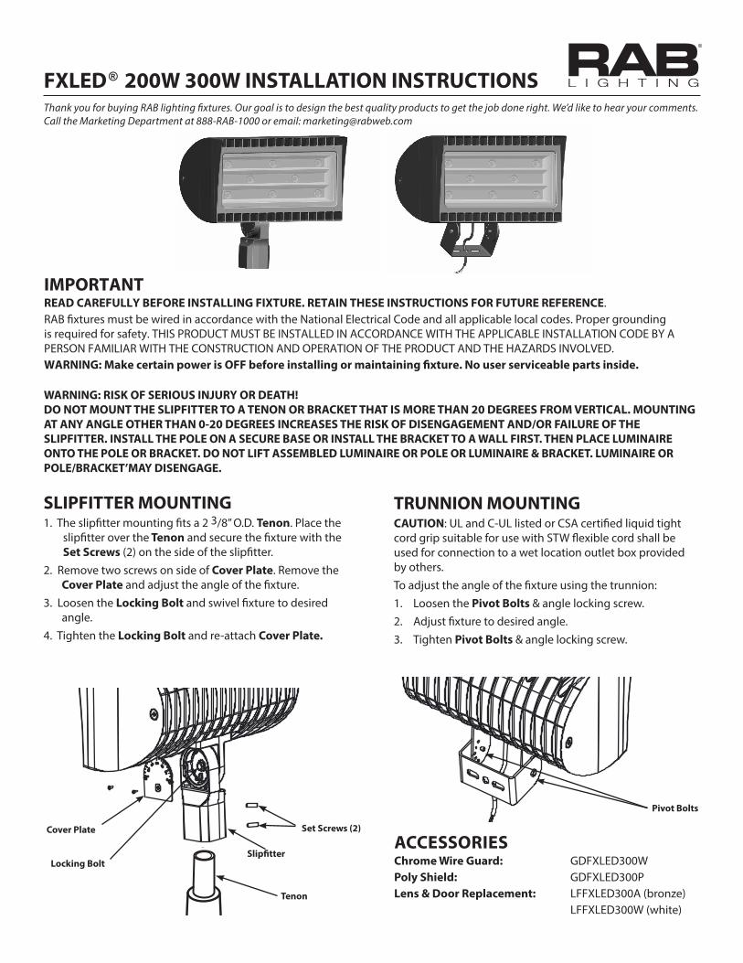
SLIPFITTER MOUNTING1. The slipfitter mounting fits a 2 3/8” O.D. Tenon. Place the
slipfitter over the Tenon and secure the fixture with the Set Screws (2) on the side of the slipfitter.
2. Remove two screws on side of Cover Plate. Remove the Cover Plate and adjust the angle of the fixture.
3. Loosen the Locking Bolt and swivel fixture to desired angle.
4. Tighten the Locking Bolt and re-attach Cover Plate.
Tenon
Set Screws (2)Cover Plate
Locking Bolt
Pivot Bolts
TRUNNION MOUNTINGCAUTION: UL and C-UL listed or CSA certified liquid tight cord grip suitable for use with STW flexible cord shall be used for connection to a wet location outlet box provided by others.To adjust the angle of the fixture using the trunnion:1. Loosen the Pivot Bolts & angle locking screw.2. Adjust fixture to desired angle.3. Tighten Pivot Bolts & angle locking screw.
WARNING: RISK OF SERIOUS INJURY OR DEATH!DO NOT MOUNT THE SLIPFITTER TO A TENON OR BRACKET THAT IS MORE THAN 20 DEGREES FROM VERTICAL. MOUNTING AT ANY ANGLE OTHER THAN 0-20 DEGREES INCREASES THE RISK OF DISENGAGEMENT AND/OR FAILURE OF THE SLIPFITTER. INSTALL THE POLE ON A SECURE BASE OR INSTALL THE BRACKET TO A WALL FIRST. THEN PLACE LUMINAIRE ONTO THE POLE OR BRACKET. DO NOT LIFT ASSEMBLED LUMINAIRE OR POLE OR LUMINAIRE & BRACKET. LUMINAIRE OR POLE/BRACKET’MAY DISENGAGE.
Slipfitter
FXLED 200W 300W INSTALLATION INSTRUCTIONSThank you for buying RAB lighting fixtures. Our goal is to design the best quality products to get the job done right. We’d like to hear your comments. Call the Marketing Department at 888-RAB-1000 or email: [email protected]
®
GUARD OR SHIELD INSTALLATIONWire Guard and Poly Shield mount with (4) #10-24 Stainless Steel Screws. Screws are provided with the accessory. See fig. 3 for Guard. See fig. 4 for Shield1. Line up guard or shield with existing pre-drilled holes in
frame as shown, tighten screws.
GUARD & SHIELD INSTALLATIONThe Wire Guard and Poly Shield can be mounted on the same fixture with (4) #10-24 screws as shown below.
Stainless Steel Screws
Fig. 3
Fig. 4
Note: These instructions do not cover all details or variations in equipment nor do they provide for every possible situation during installation, operation or maintenance.
FXLED 200 300 IN 0117
Patent - US: pat. D659,280
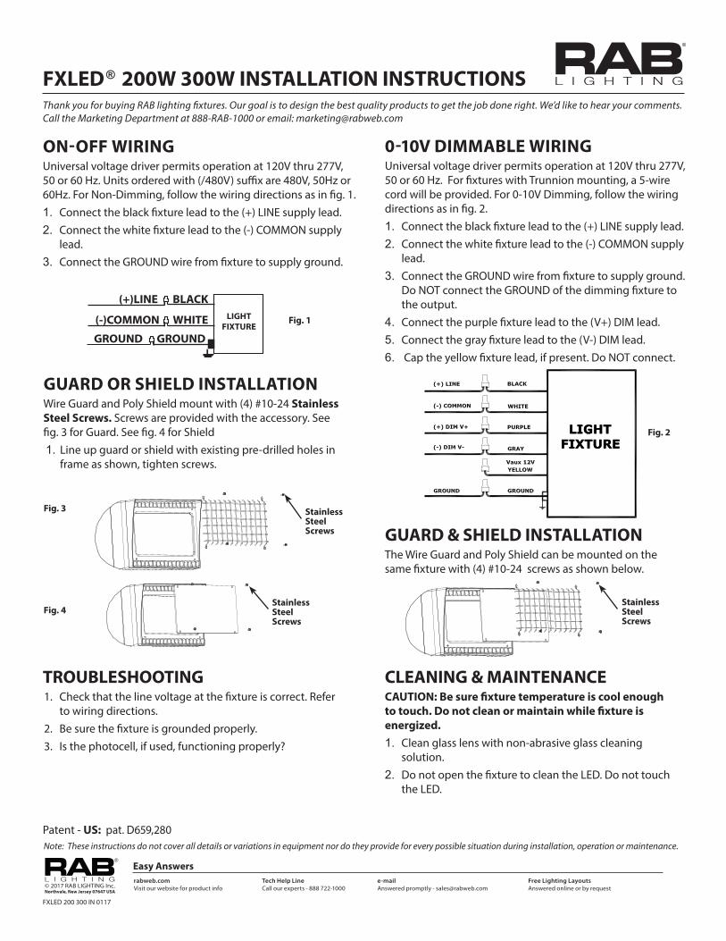
ON-OFF WIRINGUniversal voltage driver permits operation at 120V thru 277V, 50 or 60 Hz. Units ordered with (/480V) suffix are 480V, 50Hz or 60Hz. For Non-Dimming, follow the wiring directions as in fig. 1.1. Connect the black fixture lead to the (+) LINE supply lead.2. Connect the white fixture lead to the (-) COMMON supply
lead.3. Connect the GROUND wire from fixture to supply ground.
LIGHTFIXTURE
(+)LINE BLACK
(-)COMMON WHITE
GROUND GROUND
Fig. 1
Fig. 2
0-10V DIMMABLE WIRINGUniversal voltage driver permits operation at 120V thru 277V, 50 or 60 Hz. For fixtures with Trunnion mounting, a 5-wire cord will be provided. For 0-10V Dimming, follow the wiring directions as in fig. 2.1. Connect the black fixture lead to the (+) LINE supply lead.2. Connect the white fixture lead to the (-) COMMON supply
lead.3. Connect the GROUND wire from fixture to supply ground.
Do NOT connect the GROUND of the dimming fixture to the output.
4. Connect the purple fixture lead to the (V+) DIM lead.5. Connect the gray fixture lead to the (V-) DIM lead.6. Cap the yellow fixture lead, if present. Do NOT connect.
Stainless Steel Screws
Stainless Steel Screws
CLEANING & MAINTENANCECAUTION: Be sure fixture temperature is cool enough to touch. Do not clean or maintain while fixture is energized.1. Clean glass lens with non-abrasive glass cleaning
solution.2. Do not open the fixture to clean the LED. Do not touch
the LED.
TROUBLESHOOTING 1. Check that the line voltage at the fixture is correct. Refer
to wiring directions.2. Be sure the fixture is grounded properly.3. Is the photocell, if used, functioning properly?
Easy Answersrabweb.comVisit our website for product info