34
ni.com RADAR Design, Simulation and Test Jacques Cilliers
| Date post: | 23-May-2018 |
| Category: |
Documents |
| Upload: | duongtuong |
| View: | 259 times |
| Download: | 8 times |

ni.com
RADAR
Design, Simulation and Test
Jacques Cilliers
2ni.com
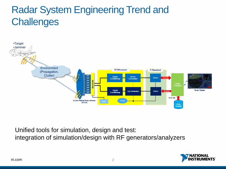
Radar System Engineering Trend and
Challenges
•Target
•Jammer
Environment
(Propagation,
Clutter)
Unified tools for simulation, design and test:
integration of simulation/design with RF generators/analyzers
3ni.com
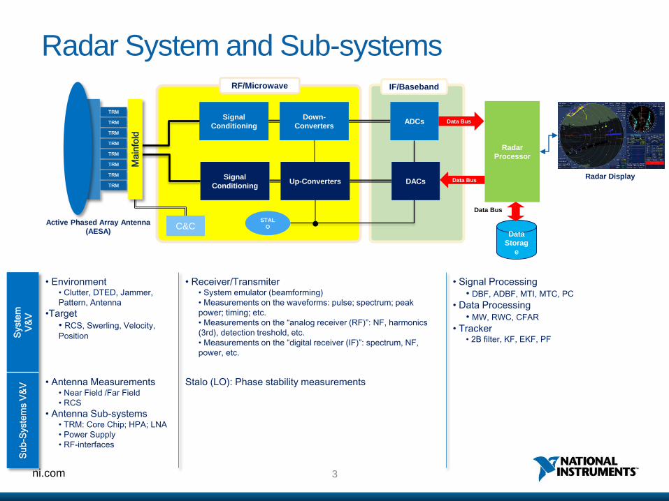
Radar System and Sub-systems
Syste
m
V&
V
• Environment • Clutter, DTED, Jammer,
Pattern, Antenna
•Target
• RCS, Swerling, Velocity,
Position
• Receiver/Transmiter• System emulator (beamforming)
• Measurements on the waveforms: pulse; spectrum; peak
power; timing; etc.
• Measurements on the “analog receiver (RF)”: NF, harmonics
(3rd), detection treshold, etc.
• Measurements on the “digital receiver (IF)”: spectrum, NF,
power, etc.
• Signal Processing
• DBF, ADBF, MTI, MTC, PC
• Data Processing
• MW, RWC, CFAR
• Tracker• 2B filter, KF, EKF, PF
Su
b-S
yste
ms V
&V • Antenna Measurements
• Near Field /Far Field
• RCS
• Antenna Sub-systems• TRM: Core Chip; HPA; LNA
• Power Supply
• RF-interfaces
Stalo (LO): Phase stability measurements
Data
Storag
e
Radar
Processor
RF/Microwave IF/Baseband
Data Bus
Data Bus
ADCs Data BusSignal
Conditioning
Down-
Converters
STAL
O
Signal
ConditioningUp-Converters DACs
Active Phased Array Antenna
(AESA)
Radar Display
TRM
TRM
TRM
TRM
TRM
TRM
TRM
TRM
Ma
info
ld
C&C

4ni.com
Sub-system
Simulation, Design and Test Sub-system Test
System Simulation, Design and Test System Test
Radar System Simulation, Design and TestMeasurements in the RF Design Flow
Logistic
Support
(MRO)
Concept of
Operations
System
Specifications
High-Level
Design
Detailed
Design
Unit/Device
Testing
System
Testing
Subsystems
Testing
Acceptance
Testing
Software/Hardware Development
Validating the System
Verifying the System
Verifying the Subsystems
Verifying the
Units/Devices
>> Implementation >>

5ni.com
PORTDOUTPORTDIN AMP_B
1 2
NL_S
ISOLATOR
M_PROBE
BPFB
MMIC PA
340MHz
10MHz
8665MHz
9015MHz
Behavioral PA
or
BPFE BPFBBPFBBPFB AMP_BAMP_B
TP
TONETONE
IN OUT
LO
MIXER_B
IN OUT
LO
MIXER_B BPFE
AMP_B
BPFBAMP_BBPFB
M_PROBE
INOUT
LO
MIXER_B
TONE
BPFEAMP_B
INOUT
LO
MIXER_B BPFE
TONE
AMP_B
BPFBPORTDOUT
PORTDIN
LNA9015MHz
8665MHz
350MHz10MHz
340MHz
Environment Antenna ProcessingExciter Receiver
Radar System Simulation
MTD
6ni.com
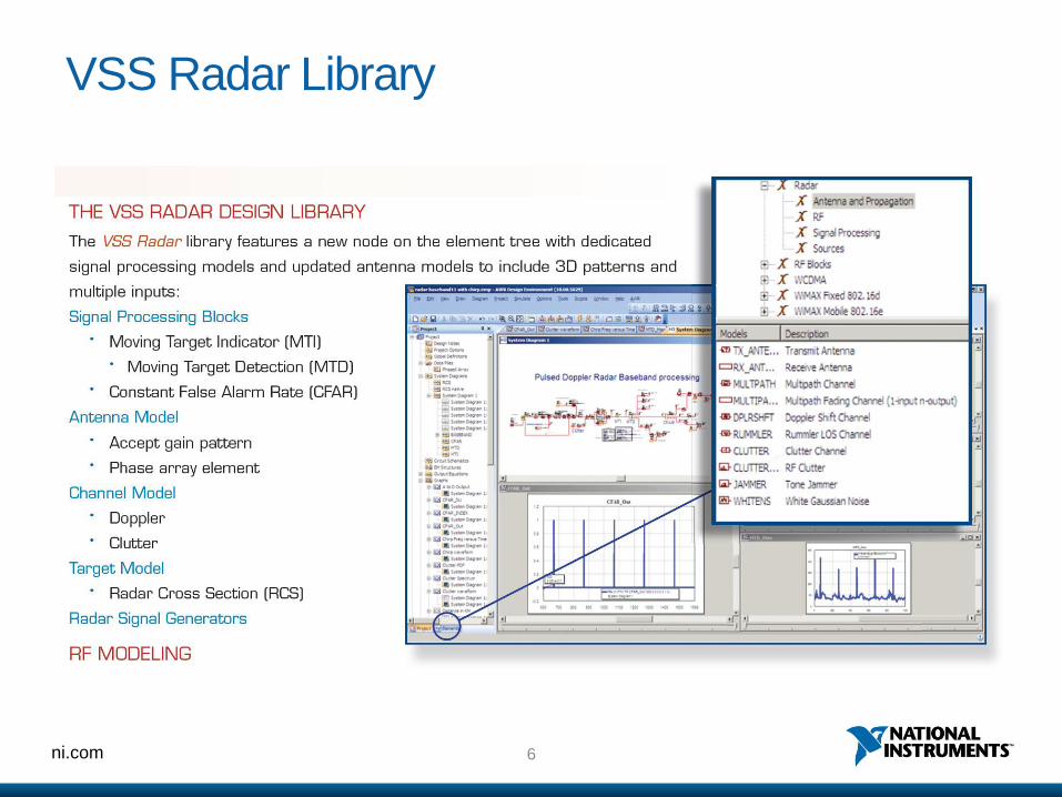
VSS Radar Library
7ni.com
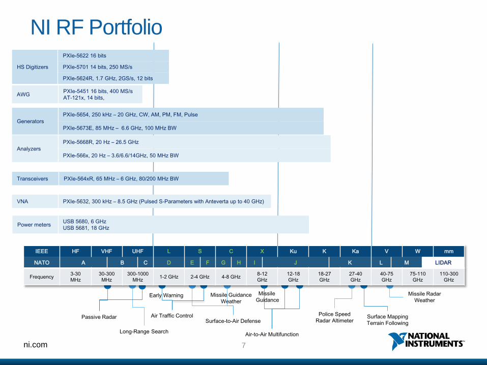
NI RF Portfolio
Long-Range Search
IEEE HF VHF UHF L S C X Ku K Ka V W mm
NATO A B C D E F G H I J K L M LIDAR
Frequency3-30
MHz
30-300
MHz
300-1000
MHz1-2 GHz 2-4 GHz 4-8 GHz
8-12
GHz
12-18
GHz
18-27
GHz
27-40
GHz
40-75
GHz
75-110
GHz
110-300
GHz
Surface-to-Air Defense
Missile Guidance
Weather
Air Traffic Control
Air-to-Air Multifunction
Missile
Guidance
Police Speed
Radar Altimeter
Missile Radar
Weather
Surface Mapping
Terrain FollowingPassive Radar
Early Warning
Analyzers
PXIe-5668R, 20 Hz – 26.5 GHz
PXIe-566x, 20 Hz – 3.6/6.6/14GHz, 50 MHz BW
Generators
PXIe-5654, 250 kHz – 20 GHz, CW, AM, PM, FM, Pulse
PXIe-5673E, 85 MHz – 6.6 GHz, 100 MHz BW
Transceivers PXIe-564xR, 65 MHz – 6 GHz, 80/200 MHz BW
HS Digitizers
PXIe-5622 16 bits
PXIe-5701 14 bits, 250 MS/s
PXIe-5624R, 1.7 GHz, 2GS/s, 12 bits
VNA PXIe-5632, 300 kHz – 8.5 GHz (Pulsed S-Parameters with Anteverta up to 40 GHz)
Power metersUSB 5680, 6 GHz
USB 5681, 18 GHz
AWGPXIe-5451 16 bits, 400 MS/s
AT-121x, 14 bits,

8ni.com
PXIe System Capabilities
Data Transfer and Latency:
• Peer-to-Peer 3.2 GB/s slot-to-slot in <10us
PXIe x 8 Gen2 3.2 GB/s per slot
PXI Express timing and synchronization
PXImc
2.7 GB/s
Up to 3.6 GB/s, 24 TB
PXIe-
6592R
9ni.com
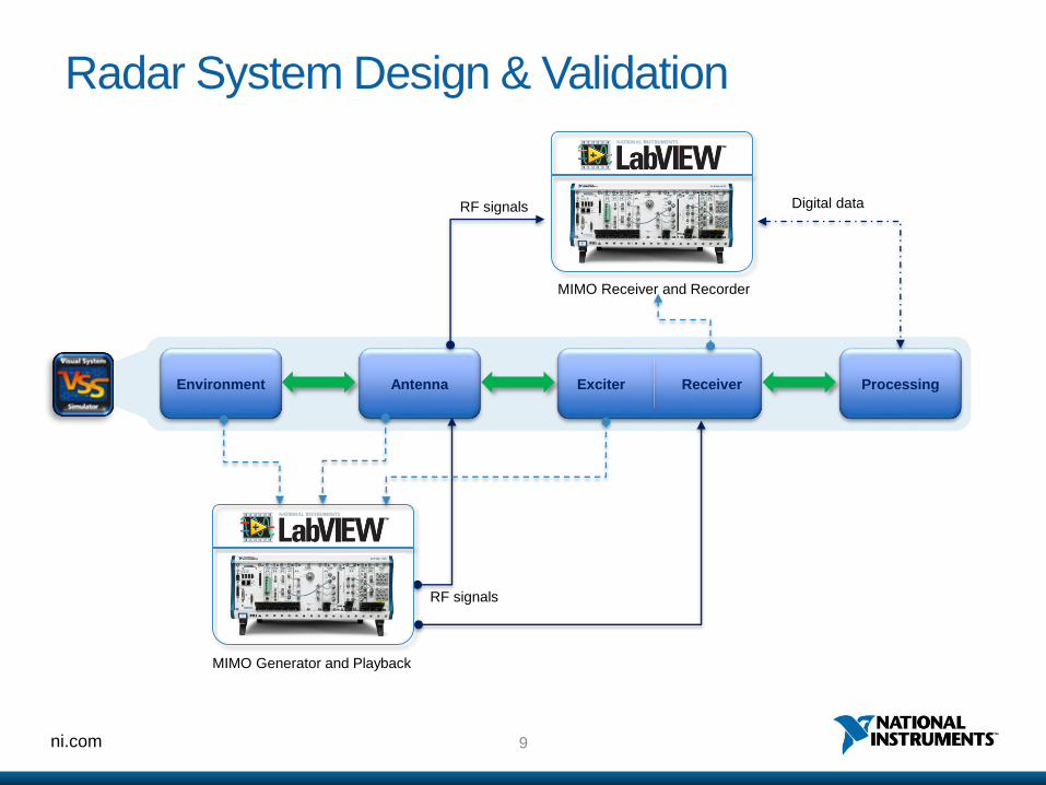
Radar System Design & Validation
Environment Antenna ProcessingExciter Receiver
RF signals
Digital data
MIMO Generator and Playback
RF signals
MIMO Receiver and Recorder

10ni.com
Passive RADAR Design in PXI
“We chose NI products is because of the user-friendly environment to
develop the software”
- Dr. Riccardo Mancinelli, Selex Sistemi Integrati

ni.com
System Design and Simulation
12ni.com
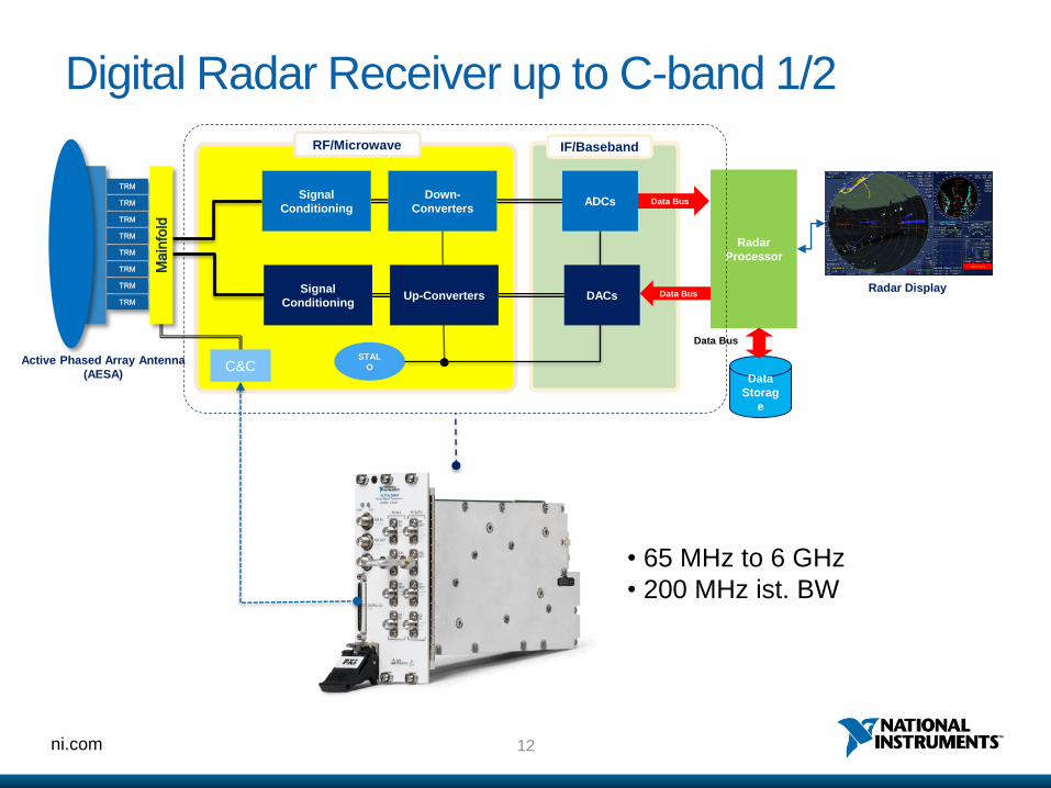
Digital Radar Receiver up to C-band 1/2
• 65 MHz to 6 GHz
• 200 MHz ist. BW
Data
Storag
e
Radar
Processor
RF/Microwave IF/Baseband
Data Bus
Data Bus
ADCs Data BusSignal
Conditioning
Down-
Converters
STAL
O
Signal
ConditioningUp-Converters DACs
Active Phased Array Antenna
(AESA)
Radar Display
TRM
TRM
TRM
TRM
TRM
TRM
TRM
TRM
Ma
info
ld
C&C
13ni.com
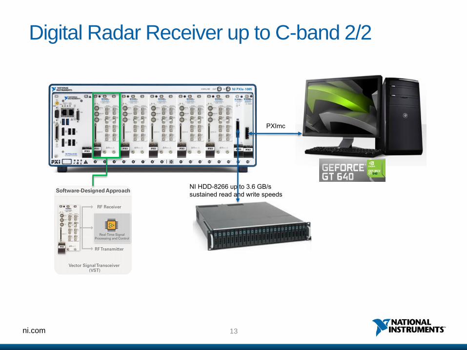
Digital Radar Receiver up to C-band 2/2
NI HDD-8266 up to 3.6 GB/s
sustained read and write speeds
PXImc

14ni.com
System-in-Loop Testing
• Definition
• Studying the behavior of a system
against a stimuli by mathematically
modeling the system, sub-systems, its
performance environment and the
linkages to other sources of influence.
15ni.com
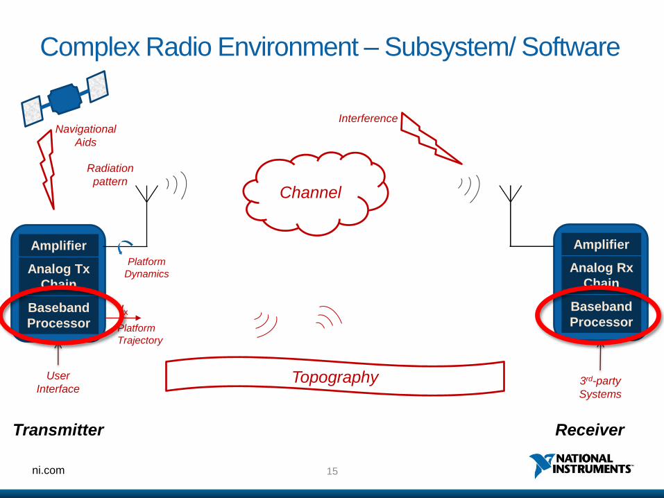
Complex Radio Environment – Subsystem/ Software
Baseband
Processor
Analog Tx
Chain
Amplifier
Radiation
pattern
vx
Platform
Trajectory
Baseband
Processor
Analog Rx
Chain
Amplifier
Channel
Platform
Dynamics
Topography
InterferenceNavigational
Aids
Transmitter Receiver
User
Interface3rd-party
Systems

16ni.com
Complex Radio Environment - Components
Baseband
Processor
Analog Tx
Chain
Amplifier
Radiation
pattern
vx
Platform
Trajectory
Baseband
Processor
Analog Rx
Chain
Amplifier
Channel
Platform
Dynamics
Topography
InterferenceNavigational
Aids
Transmitter Receiver
User
Interface3rd-party
Systems

17ni.com
Complex Radio Environment – External Linkages
Baseband
Processor
Analog Tx
Chain
Amplifier
Radiation
pattern
vx
Platform
Trajectory
Baseband
Processor
Analog Rx
Chain
Amplifier
Channel
Platform
Dynamics
Topography
InterferenceNavigational
Aids
Transmitter Receiver
User
Interface3rd-party
Systems

18ni.com
Complex Radio Environment - Channel
Baseband
Processor
Analog Tx
Chain
Amplifier
Radiation
pattern
vx
Platform
Trajectory
Baseband
Processor
Analog Rx
Chain
Amplifier
Channel
Platform
Dynamics
Topography
InterferenceNavigational
Aids
Transmitter Receiver
User
Interface3rd-party
Systems
19ni.com
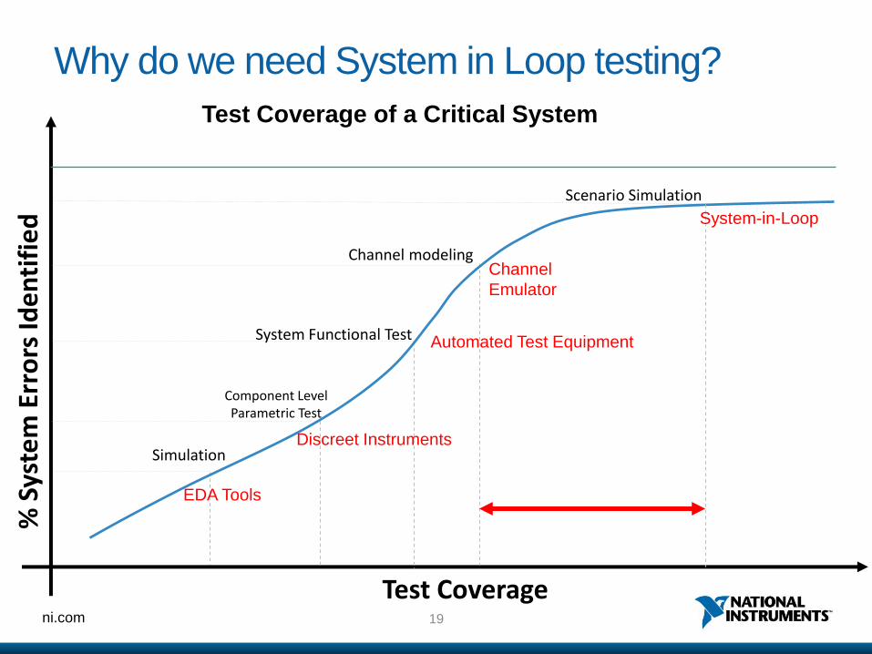
Why do we need System in Loop testing?%
Sys
tem
Err
ors
Ide
nti
fie
d
Test Coverage
Simulation
Component Level Parametric Test
System Functional Test
Channel modeling
EDA Tools
Discreet Instruments
Automated Test Equipment
Channel
Emulator
Scenario Simulation
System-in-Loop
Test Coverage of a Critical System
20ni.com
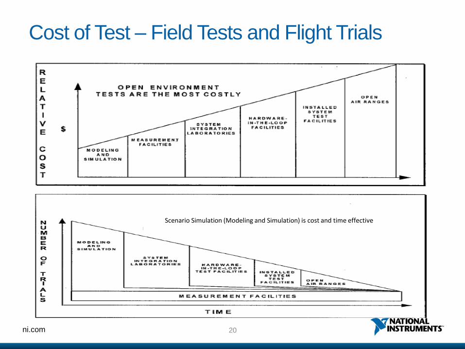
Cost of Test – Field Tests and Flight Trials
Scenario Simulation (Modeling and Simulation) is cost and time effective
ni.com
Efficient architecture for system-in-loop testing

22ni.com
System Modeling and Simulation
Bus technology
RF/uW
DownconverterIF Digitizer
Signal
ProcessingIF AWG
RF/uW
Upconverter
Math
Model
23ni.com
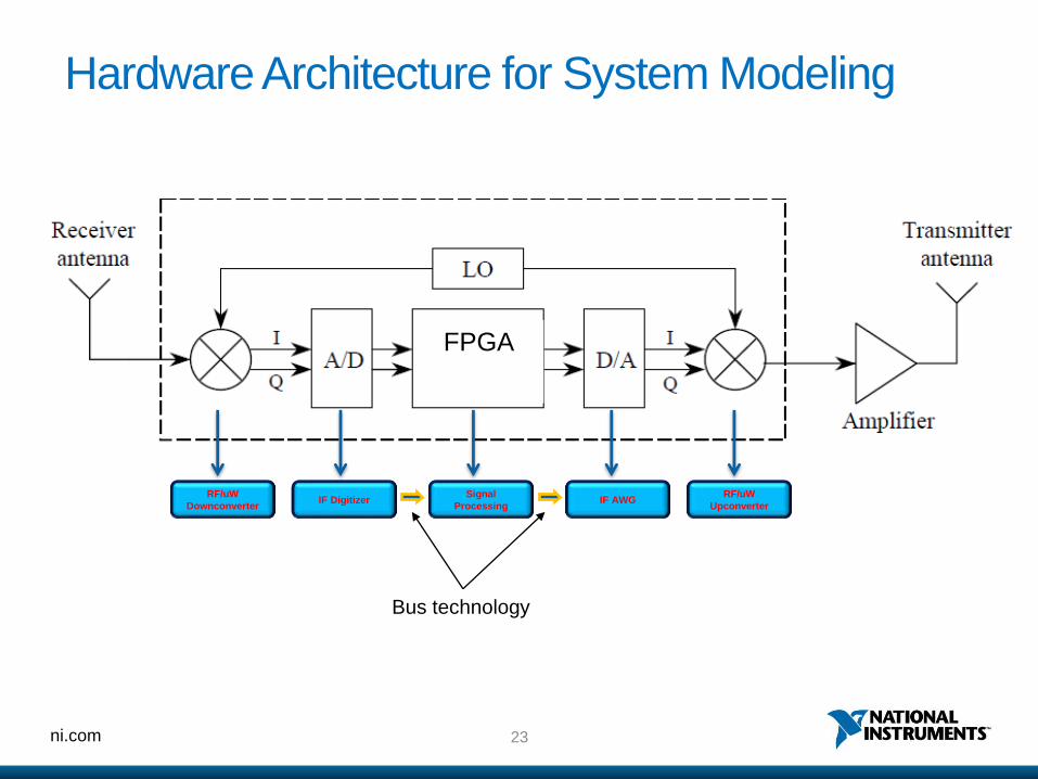
Hardware Architecture for System Modeling
Bus technology
RF/uW
DownconverterIF Digitizer
Signal
ProcessingIF AWG
RF/uW
Upconverter
FPGA

ni.com
COTS Platform for System Modeling
25ni.com
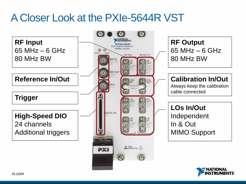
A Closer Look at the PXIe-5644R VST
RF Input
65 MHz – 6 GHz
80 MHz BW
RF Output
65 MHz – 6 GHz
80 MHz BW
Reference In/Out
High-Speed DIO
24 channels
Additional triggers
LOs In/Out
Independent
In & Out
MIMO Support
Calibration In/OutAlways keep the calibration
cable connected
Trigger
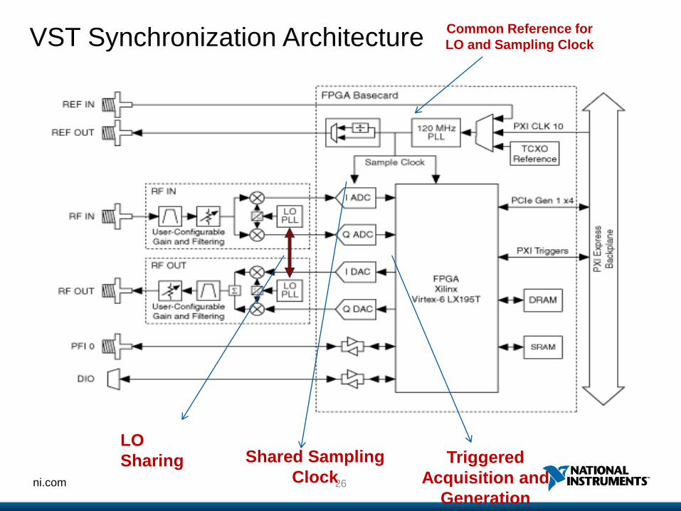
26ni.com
LO
Sharing Shared Sampling
ClockTriggered
Acquisition and
Generation
Common Reference for
LO and Sampling ClockVST Synchronization Architecture

27ni.com

28ni.com
Software-Designed InstrumentationCompletely Open-Source Driver Ensures Ultimate Flexibility
The vector signal transceiver is ready to run out of the box, but the driver
is written entirely in LabVIEW, giving you direct access to the instruments
I/O.
29ni.com
Examples
30ni.com
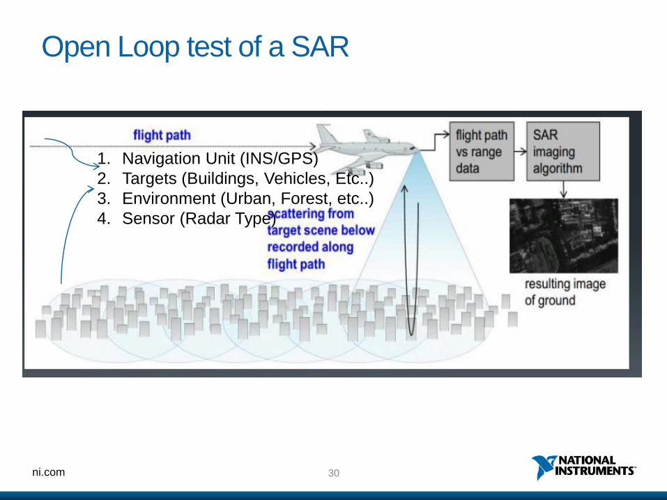
Open Loop test of a SAR
1. Navigation Unit (INS/GPS)
2. Targets (Buildings, Vehicles, Etc..)
3. Environment (Urban, Forest, etc..)
4. Sensor (Radar Type)

31ni.com
Simulation Capabilities of SAR Echo Simulator
Scenario Generation
a) Type of Modes – Strip Mode and Spot Light mode
b) Defining of Platforms, Sensor, Environment, Mission area,
Point reflectors etc…
c) Flight Preview (animation)
d) Raw Data Generation
e) Raw Data Processing
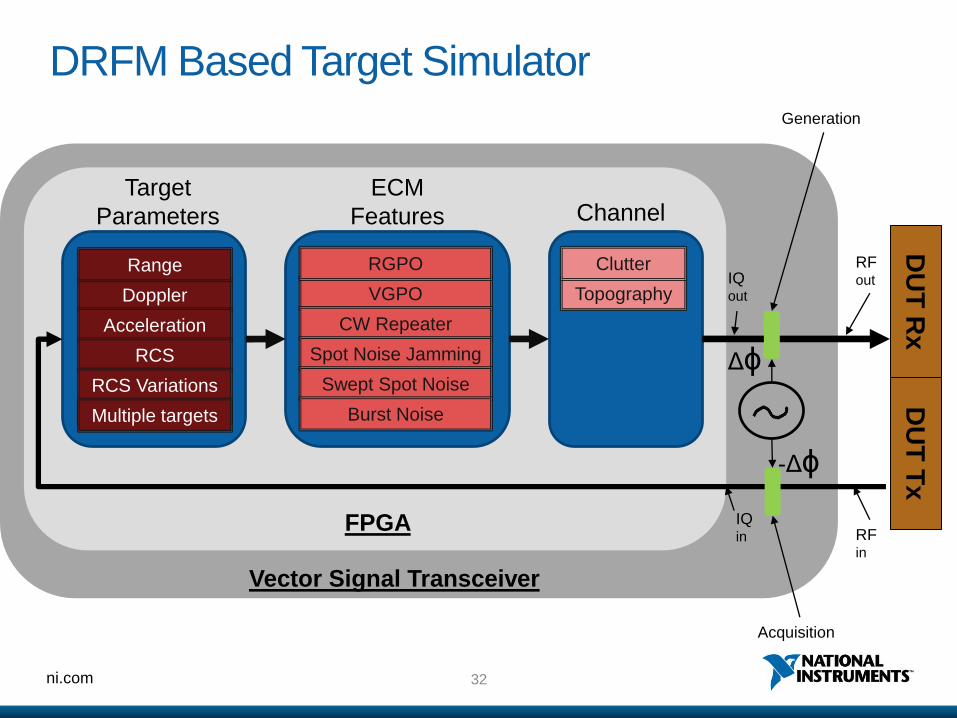
32ni.com
DRFM Based Target Simulator
FPGA
Generation
Doppler
Range
Acceleration
RCS
RCS Variations
Multiple targets
Target
Parameters
VGPO
RGPO
CW Repeater
Spot Noise Jamming
Swept Spot Noise
Burst Noise
ECM
Features
Topography
Clutter
Channel
DU
T R
xD
UT
Tx
Acquisition
Δɸ
-Δɸ
IQ out
IQ in
Vector Signal Transceiver
RF in
RF out

33ni.com
Target Generator
RF OutRF In
•Delay (memory)
•Range
•Radar Cross Section
•Doppler Shift

34ni.com
Thank you


