32
Radiant Heat Test Facility (RHTF) User Test Planning Guide National Aeronautics and Space Administration Lyndon B. Johnson Space Center Houston, Texas 77058

Radiant Heat Test Facility (RHTF)
User Test Planning Guide
National Aeronautics and Space Administration Lyndon B. Johnson Space Center Houston, Texas 77058

2
Table of Contents
1.0 Radiant Heat Test Facility ................................................................................................3
2.0 Facility Layout ...................................................................................................................5
3.0 Safety and Health ..............................................................................................................6
4.0 Test Process Flow ............................................................................................................64.1. Export Controlled and Proprietary Information .................................................................7
4.2 Test Initiation Phase ........................................................................................................84.2.1 Test Request ...................................................................................................................... 8
4.2.2 Schedule and Cost Estimate ............................................................................................... 9
4.3 Test Preparation Phase ...................................................................................................94.3.1 Test Requirements ............................................................................................................. 9
4.3.2 Test Article Documentation ................................................................................................. 9
4.3.3 Test Plan .......................................................................................................................... 10
4.3.4 Test Schedule ................................................................................................................... 10
4.3.5 Test Article Delivery .......................................................................................................... 10
4.3.6 Test Readiness Review .................................................................................................... 11
4.4 Test Execution Phase .................................................................................................... 114.4.1 Test Authority ................................................................................................................... 12
4.4.2 Test Deviations ................................................................................................................. 12
4.5 Test Closeout Phase ..................................................................................................... 124.5.1 Customer Feedback ......................................................................................................... 12
5.0 Facility Access ................................................................................................................ 13
6.0 Roles and Responsibilities ............................................................................................ 14
Acronyms .................................................................................................................................. 15
Appendices ............................................................................................................................... 16Appendix A Facility Layout/Interfaces .................................................................................. 17
Appendix B Sample Test Configurations ............................................................................. 19
Appendix C Instrumentation Provided by Facility * .............................................................. 23
Appendix D Test Request Worksheet .................................................................................. 24
Appendix E RHTF Visitor Orientation .................................................................................. 28
Appendix F Customer Feedback ......................................................................................... 32

3
1.0 Radiant Heat Test Facility The Radiant Heat Test Facility (RHTF) was designed for development and certification tests for the Orbiter thermal protection system. This facility has been maintained continuously to the present time to support sustaining engineering of the Orbiter and other National Aeronautics and Space Administration (NASA) test programs. The facility has two test chambers, R1 and R2.
Radiant Heat Test Chamber 1
R1 is 10′ in diameter and 18′ long. This facility can be configured to test wing panels with up to 22 separately-controlled heater zones with the heaters arranged in a curved configuration to follow the wing contour. These heaters also can be arranged in a flat panel array, measuring 74″ x 110″. The heaters are approximately 5″ wide and can be configured for either a 48″ length or 74″ length. The heater arrays have the capability to easily achieve a temperature of 2600 °F and well beyond, depending on the makeup of the test article.
Radiant Heat Test Chamber2
R2 is 92″ in diameter and 92″ long. A graphite heater with a coated columbium susceptor is mounted in the top of the chamber with the heated source side oriented downward. This chamber/heater combination can simulate launch pressure decay, on-orbit cold-soak, and reentry heating and pressure environments. A water-cooled shutter may be inserted between the heater and test article to allow the heater to be prewarmed before the test article is exposed or to assist in the more rapid cool down of the test article. Temperatures up to 2600 °F may be achieved with the susceptor in place, allowing the surrounding atmosphere to be air. If a nitrogen atmosphere is used, the susceptor may be removed and temperatures approaching 2900 °F can be induced, depending on the type of test article.

4
Specifications
Type Test Chamber 1 (R1) Test Chamber 2 (R2) Physical Dimensions 10′ dia 18 ft length 92″ dia 92″ length Gas Air, N Air, N2 2 Heater 1 – 5 MW 1 – 5 MW
Sample Size 72″ x 110″ 24″ x 24″
Test Article Type Flat, radically curved Flat, small curvature
Pressure Range 0.01 to 760 torr (220,000′ – sea level) 0.01 to 760 torr (220,000′ – sea level) Temperature Range 0 – 2,900 °F+ −150 °F – 2,600 °F+ Radiative Heating Rate, BTU/Ft2 0 to 90 entry profile, 22 zones -Sec 0 to 90 entry profile, 1 zone
Data Acquisition 256 channels 256 channels
Services Provided Unique Capabilities
• Simulation of:
– Ascent heating and pressure decay
– On-orbit cold soak
– Reentry heating and pressure
• Large-scale systems tests
– FRSl/HRSl Test Panels
– Reinforced Carbon-Carbon (RCC) panels
– Nose cap
– Wing leading edge
• Small-scale tests
– Materials screening
– Conductivity testing
– Advanced materials
• Altitude simulation
– .01 to 760 torr (220,000′ – sea level)
• On-orbit cold soak
– –
• Reentry heating
150 °F bondline temperature within 3½ hours
– Temperatures > 2,600 °F
– 5 MW heater
– 22 control channels
Point of Contact
Lab Manager, Steven Del Papa Johnson Space Center 2101 NASA Parkway Houston, TX 77058 (281) 483-8960 [email protected]

5
2.0 Facility Layout
* See Appendix A for additional facility layouts and interfaces.

6
3.0 Safety and Health Safety is an integral part of the culture at NASA. Management, leadership, and employee involvement from all organizations are critical to the success of NASA’s safety program. In order to ensure personal safety and a safe test environment throughout the process, the requester shall furnish the facility with the information necessary to perform a hazard assessment of the test article. Additionally, while visiting the Johnson Space Center (JSC), the requester shall follow all facility-specific safety and health requirements. A facility safety briefing shall be provided to all personnel prior to the start of the test. The safety briefing will include a review of the RHTF safety rules, potential hazards, and emergency procedures. An outline of the material covered is included in Appendix E.
4.0 Test Process Flow The flowchart presented below outlines the basic roadmap and significant milestones between the initial test request and delivery of test data. The flow is separated between Test Requester actions and Facility actions, highlighting interactions and inputs between the Test Requester and the facility Test Director.

7
The test schedule is highly dependent on the complexity of the test, facility availability, and sequence of runs. For time-critical testing, this schedule may be accelerated. A detailed schedule shall be developed following a review of the test objectives and requirements. Major milestones are presented below:
4.1. Export Controlled and Proprietary Information All Thermal Protection System (TPS) data is restricted by the International Traffic in Arms Regulation (ITAR) and Export Administration Regulations (EAR). The RHTF provides for protection of export controlled and proprietary information and hardware throughout the test process. The Test Requester shall clearly mark all export controlled or proprietary hardware items and data provided with a notice of restriction on disclosure or usage. The Test Director shall safeguard export controlled or proprietary items from unauthorized use and disclosure and ensure that test articles remain secure within the facility and are properly sequestered. Access to the facility is restricted to facility personnel and escorted visitors. Hardware items shall be returned to the Test Requester or disposed of in accordance with the Test Requester′s instructions at the completion of the test activity.

8
4.2 Test Initiation Phase The test initiation phase establishes the relationship between the Test Requester and the Test Director. The Test Requester shall provide a test request to the Test Director, which will be used to determine test feasibility and to develop an estimated cost and a preliminary test schedule. An initial requirements review meeting may be necessary in order to discuss the characteristics of the test article, the test approach, or any special considerations for the test. An onsite tour of the facility is highly recommended for familiarization and to provide an opportunity for an exchange of technical information. Inputs: Test Requester provides test request, identifies Test Article Expert
Activities: Facility Test Director reviews test request to determine test feasibility
Outputs: Facility delivers preliminary test plan, estimated cost and schedule to Test Requester
4.2.1 Test Request
The test request outlines the test objectives, test article description, and schedule. A Test Request Worksheet is provided in Appendix D. This worksheet addresses the basic requirements for testing in the RHTF. It is suggested that the Test Requester complete this worksheet to facilitate the development of a preliminary test plan. Contact the Test Director if you have questions about completing the Test Request Worksheet. At a minimum, the test request should include the following information:
Test Objective
A brief description of the test requirements, including, but not limited to, the following:
• Desired test conditions (pressure, temperature, exposure time) • Proposed test approach • Test data requirements
Test Article Description
A brief description of the test article, including, but not limited to, the following:
• Size (provide drawings, sketches, photos) • Weight • Test article interface (load points, method of suspension or test article support) • Orientation (fixed or moveable) • Special considerations [e.g., hazards, cleanliness, compatibility, Material Safety Data
Sheets (MSDS)] • Handling and storage requirements
Schedule

9
Identify the required start date and proposed date for test completion.
4.2.2 Schedule and Cost Estimate
Following receipt of a completed Test Request Worksheet, the Test Director will provide a cost and schedule estimate, including major milestones, to the Test Requester.
4.3 Test Preparation Phase The detailed test plan and test schedule are finalized during the test preparation phase. The Test Requester shall provide detailed test requirements and test article documentation to the Test Director. A Test Readiness Review (TRR) will be held following approval of the test plan. Inputs: Test Requester provides test requirements and test article documentation
Activities: Facility develops test plan, begins assembly of facility interface/support structure(s)
Test Requester ships/transports test article to JSC
Outputs: Test Requester approves test plan and test schedule
Facility holds TRR
4.3.1 Test Requirements
A complete understanding of test requirements is mandatory for a successful test. Test requirements must be defined and reviewed so that the test team understands the effect of the requirements on test facility preparation. The Test Requester shall provide a detailed list of test requirements, including, but not limited to, the following:
• Specific test conditions (e.g., temperature profiles/ramp rates, exposure durations, pressure/ramp rates)
• Interface requirements (e.g., structural, electrical, mechanical)
• Data/instrumentation requirements (provided by Test Requester and facility)
4.3.2 Test Article Documentation
Test Article Drawings
The Test Requester shall provide detailed test article drawings as requested by the Test Director. Test article drawings are used to prepare the facility interfaces, test article support structures, and instrumentation connection points.
10
Material Safety Data Sheets
NASA must ensure that all materials exposed to test environments do not present a hazard to personnel or the test facility. The Test Requester shall deliver to the facility MSDS for materials used in the construction of the test article with an assessment of expected byproducts produced during the thermal test. The MSDS shall be delivered prior to delivery of the test article. The Test Director will review the materials list for compatibility with the test environment and to determine protective measures for personnel, if required. Test Article Hazard Identification
The safety of facility personnel, facility equipment, and the test article is imperative to NASA. Potential hazards, material compatibility, and facility interfaces will be reviewed with the facility prior to testing. In certain instances, special precautions must be taken due to the severity level of these potential hazards. The Test Requester may be asked to provide further information to clarify or mitigate a potential hazard.
4.3.3 Test Plan
A test plan will be prepared by the Test Director, unless one is submitted by the Test Requester. The final test plan shall be approved by the Test Requester with concurrence from the Test Director. The test plan will be the controlling document, with respect to scope and approach for the test program. The test plan will include, at a minimum, the test objectives, scope, test article description, safety considerations, and data requirements. Changes to the test plan that occur after the TRR that result in a major change to the scope of the test or that present new hazards may require a delta TRR.
4.3.4 Test Schedule
A detailed schedule shall be developed by the Test Director and approved by the Test Requester. The schedule shall allow adequate time for review and approval of test requirements, assembly of facility interfaces/structures and delivery of the test article. The schedule of other tests and maintenance activities will be reviewed and potential conflicts shall be addressed by the Test Director.
4.3.5 Test Article Delivery
The test article delivery date will be determined on a case-by-case basis. An agreed-upon delivery date shall be captured as a milestone in the test schedule. The Test Requester shall provide detailed handling instructions prior to delivery of the test article, including handling hazards, cleanliness, and storage requirements. The test article shall be secured within the test facility, unless directed to provide another means of storage. An inspection of the test article shall be performed by the Test Director and the Test Article Expert prior to the start of testing. NASA encourages Test Article Expert participation in the test article integration phase to provide immediate feedback on test article handling and on any integration issues that arise.

11
4.3.6 Test Readiness Review
A TRR will be held to ensure the completion of all necessary facility and test article activities prior to test execution. The TRR will include the following:
• Review of the test plan, test procedures, and other required test documentation • Confirmation of facility and test article readiness • Review of configuration records, including facility interface control documents, pressure
system certification, instrumentation calibration, and materials compatibility • Assurance that controls are in place to mitigate risks or hazards identified in the test
article hazard analysis • Verification that data acquisition and processing functions are in place to adequately
capture all critical data • Confirmation that multimedia coverage is adequate to provide recognition and
assessment of potential test anomalies Approval to proceed with test operations is granted by the Test Readiness Review Board (TRRB). The Test Director shall ensure that all TRR actions have been accomplished prior to the start of the test. The TRRB shall convene 1 to 5 business days prior to the start of the test. TRRB participants shall include the following:
NASA TRRB Chairman Test Article Expert (Appointed by Test Requester)
Test Director Safety Engineer
NASA Test Safety Officer Quality Engineer – if required by facility
4.4 Test Execution Phase NASA encourages Test Requester participation in the testing activity. The Test Requester shall provide a Test Article Expert to verify that test setup and execution meet the stated objectives. The Test Article Expert also shall verify test article performance and approve requested test deviations during test operations. In some cases, the Test Director may be designated as the Test Article Expert. Inputs: Approval to begin testing received from TRRB
Activities: Facility completes buildup, Detailed Test Procedure
Facility conducts testing activity
Outputs: Test completed

12
4.4.1 Test Authority
The Test Director has the authority and responsibility to direct the test in accordance with the approved test plan and to terminate test activities per test rules when danger is imminent or test control cannot be maintained. The Test Director will ensure that positive actions are taken to halt any steps in the test procedure whenever unsafe or hazardous test conditions arise. The Test Director, with the concurrence of the Test Article Expert, has the authority to terminate the test when sufficient data has been obtained to meet objectives or when objectives cannot be met. Test team personnel will accept directions only from the Test Director.
4.4.2 Test Deviations
Changes to the test procedure shall be approved by the Test Article Expert with concurrence from the Test Director. Deviations that result in a major change to the scope of the test or that present new hazards may require a delta TRR.
4.5 Test Closeout Phase Data shall be delivered to the Test Requester within 10 business days following completion of testing. The Test Requester shall notify the Test Director upon receipt of the data. Acceptance of the test data concludes the test activity. Inputs: Test completed
Activities: Facility ships/transports test article to Test Requester
Facility delivers data to Test Requester
Outputs: Test Requester accepts data
4.5.1 Customer Feedback
The RHTF encourages feedback from our customers. Evaluation of the services we provide enables continued improvement to our process. A Customer Feedback form is included in Appendix F. You are encouraged to complete the Customer Feedback form and return it to the Test Director, following receipt of the test data. Your participation is greatly appreciated.

13
5.0 Facility Access Identification badges are required for all persons requiring access to JSC. The Test Director or designee will initiate a badge request for all Test Requester personnel who will be participating in the test activity. Badge requests must be submitted at least 4 days prior to the visit to prevent badge processing delays. Badge requests for non-U.S. citizens may require a minimum of 30 business days to process. Test Requester personnel shall arrive at JSC Building 110 to pick up temporary identification badges. Visitors to JSC must show a current picture identification (valid driver’s license, U.S. passport, government ID card).
The RHTF is located in JSC Building 260. The test team office is located in JSC Building 222. A facility access briefing shall be provided to personnel requiring access to the facility prior to the start of the test.
14
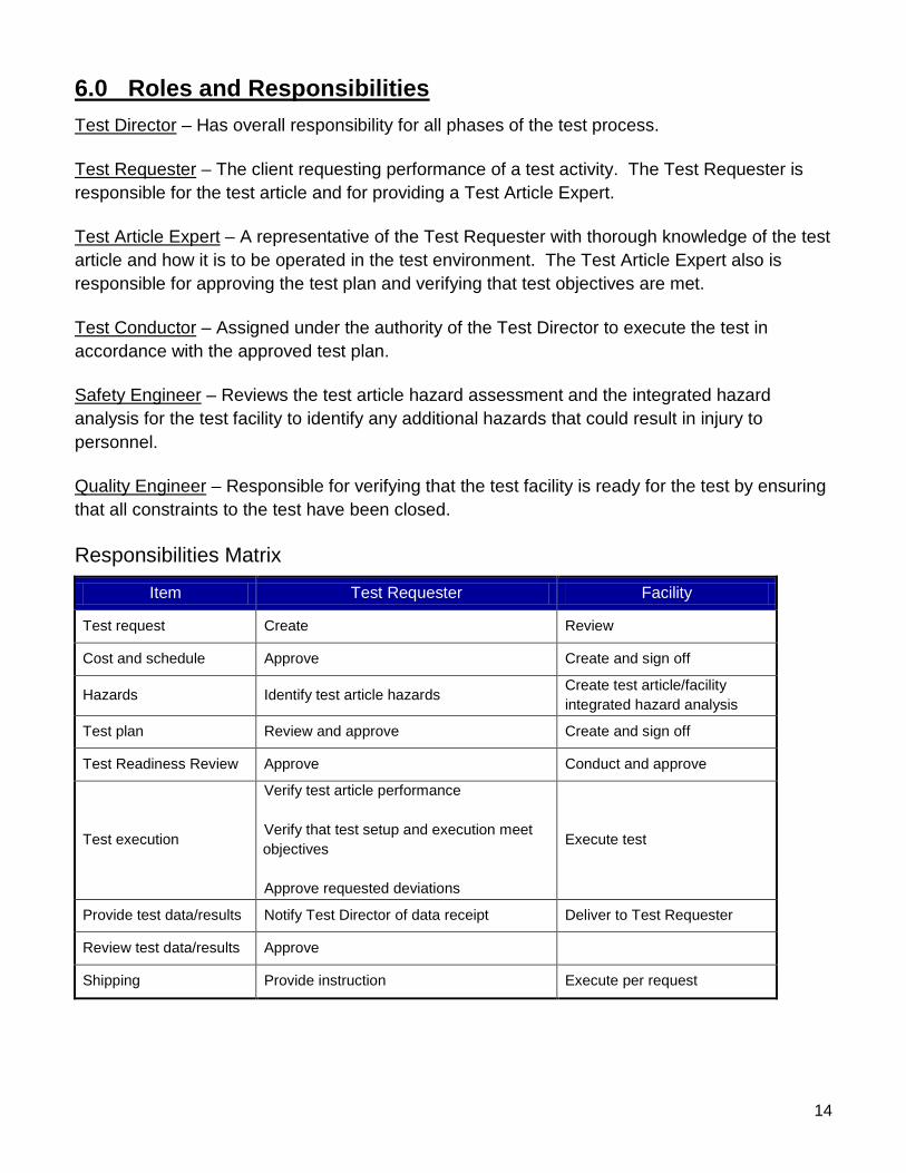
6.0 Roles and Responsibilities Test Director – Has overall responsibility for all phases of the test process. Test Requester – The client requesting performance of a test activity. The Test Requester is responsible for the test article and for providing a Test Article Expert. Test Article Expert – A representative of the Test Requester with thorough knowledge of the test article and how it is to be operated in the test environment. The Test Article Expert also is responsible for approving the test plan and verifying that test objectives are met. Test Conductor – Assigned under the authority of the Test Director to execute the test in accordance with the approved test plan. Safety Engineer – Reviews the test article hazard assessment and the integrated hazard analysis for the test facility to identify any additional hazards that could result in injury to personnel. Quality Engineer – Responsible for verifying that the test facility is ready for the test by ensuring that all constraints to the test have been closed. Responsibilities Matrix
Item Test Requester Facility
Test request Create Review
Cost and schedule Approve Create and sign off
Hazards Identify test article hazards Create test article/facility integrated hazard analysis
Test plan Review and approve Create and sign off
Test Readiness Review Approve Conduct and approve
Test execution
Verify test article performance Verify that test setup and execution meet objectives Approve requested deviations
Execute test
Provide test data/results Notify Test Director of data receipt Deliver to Test Requester
Review test data/results Approve Shipping Provide instruction Execute per request

15
Acronyms
EAR Export Administration Regulations
EOC Emergency Operations Center
FOC Facility Operations Contractor
FRSI Felt Reusable Surface Insulation
HA Hazard Analysis
HRSI High Temperature Reusable Surface Insulation
ITAR International Traffic in Arms Regulation
JHA Job Hazard Analysis
JSC Johnson Space Center
LVDT Linear Variable Differential Transformer
MSDS Material Safety Data Sheets
NASA National Aeronautics and Space Administration
OHD Occupational Health Department
POC Point-of-Contact
PPE Personal Protective Equipment
RCC Reinforced Carbon-Carbon
RHTF Radiant Heat Test Facility
RTD Resistance Temperature Detector
TC Thermocouple
TD Test Director
TPS Thermal Protection System
TRR Test Readiness Review
TRRB Test Readiness Review Board

16
Appendices
A. Facility Layout/Interfaces B. Sample Test Configurations C. Instrumentation Provided by Facility D. Test Request Worksheet E. RHTF Visitor Orientation F. Customer Feedback

17
Appendix A Facility Layout/Interfaces
Heater Configurations
Flat Array – 4 ft and 6 ft Heaters Assembled in Flat Array Configurations
The 4 ft heater is presented in the background and 6 ft heater in the foreground
Flat Heater Array 6 ft Heaters Ready for Installation
22 Wing Leading Edge Heaters in Leading Edge Configuration

18
Graphite elements not shown With graphite elements Orbiter Wing Leading Edge Going into Chamber R1
Full-scale orbiter wing panels with wing structure/thermal certification tests

19
0
100
200
300
400
500
600
700
800
0
200
400
600
800
1000
1200
1400
1600
-200 0 200 400 600 800 1000 1200 1400 1600 1800 2000 2200
DESIRED TEMP (F) CHAN-57 2455-TC1 DEG.F
DESIRED PRESSURE (torr) CHAN-2 VACUUM TORR
TEM
PE
RA
TUR
E (D
EG
F)
TIME (SECONDS)
PR
ES
SU
RE
(tor
r)
Appendix B Sample Test Configurations
Sample Material Characterization
20
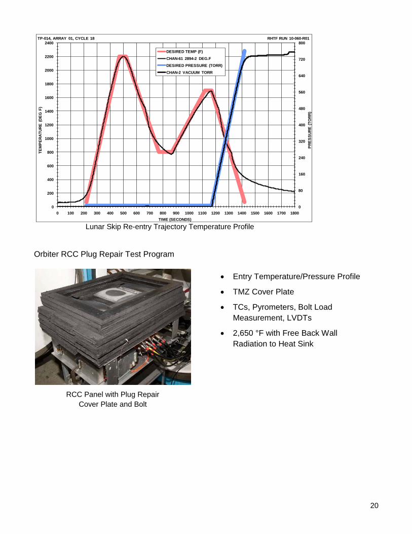
Lunar Skip Re-entry Trajectory Temperature Profile Orbiter RCC Plug Repair Test Program
0
80
160
240
320
400
480
560
640
720
800
0
200
400
600
800
1000
1200
1400
1600
1800
2000
2200
2400
0 100 200 300 400 500 600 700 800 900 1000 1100 1200 1300 1400 1500 1600 1700 1800
DESIRED TEMP (F)
CHAN-61 2894-2 DEG.F
DESIRED PRESSURE (TORR)
CHAN-2 VACUUM TORR
TP-014, ARRAY 01, CYCLE 18 RHTF RUN 10-060-R01TE
MPE
RATU
RE (D
EG F
)
TIME (SECONDS)
PRES
SURE
(TO
RR)
RCC Panel with Plug Repair Cover Plate and Bolt
• Entry Temperature/Pressure Profile
• TMZ Cover Plate
• TCs, Pyrometers, Bolt Load Measurement, LVDTs
• 2,650 °F with Free Back Wall Radiation to Heat Sink

21
Shuttle Nose Cap System Certification Test
Water-Cooled Load Train 0.01″ dia Target Area Fiber Optic Pyrometers
Orbiter Nose Cap
Orbiter Nose Cap
Independently controlled heater zones to produce the required thermal gradients

22
X-33 Iso-grid (Metallic Honeycomb) Test Article
Tile Array Calibration Model with Thermocouples imbedded in tile surfaces and heating rate sensors (small dark circles) located in gaps between tiles.
Back view of X-33 Iso-grid
23
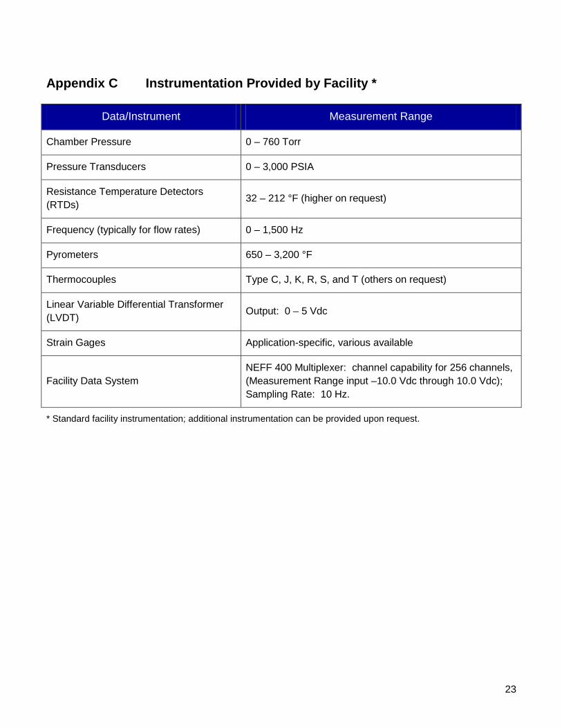
Appendix C Instrumentation Provided by Facility *
Data/Instrument Measurement Range
Chamber Pressure 0 – 760 Torr
Pressure Transducers 0 – 3,000 PSIA
Resistance Temperature Detectors (RTDs) 32 – 212 °F (higher on request)
Frequency (typically for flow rates) 0 – 1,500 Hz
Pyrometers 650 – 3,200 °F
Thermocouples Type C, J, K, R, S, and T (others on request)
Linear Variable Differential Transformer (LVDT) Output: 0 – 5 Vdc
Strain Gages Application-specific, various available
Facility Data System NEFF 400 Multiplexer: channel capability for 256 channels, (Measurement Range input –10.0 Vdc through 10.0 Vdc); Sampling Rate: 10 Hz.
* Standard facility instrumentation; additional instrumentation can be provided upon request.
END VIEW
EQUPMENT LOCK LID

24
Appendix D Test Request Worksheet Test Requester Information Test Article Expert:
Contact Information (Phone, E-mail, Address):
Test Objectives Purpose of Test:
Test Article Test Article Description:
Physical Dimensions (L/W/H):
Weight:
Optical Properties:
Number of Specimens:

25
Test Article Interface Describe Required Support Structure/Test Article Interface Points/Thermal Closeouts (Provide drawings/sketches of test article, proposed support structure, thermal closeouts):
Test Article Instrumentation (Location of thermocouples):
Test Article Power Requirements (test article, support equipment, requester-provided instrumentation):
Test Article Handling Requirements Cleanliness Level:
Controlled Access:
Special Moving/Handling:
26
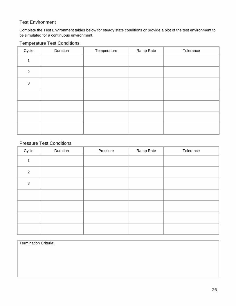
Test Environment
Complete the Test Environment tables below for steady state conditions or provide a plot of the test environment to be simulated for a continuous environment.
Temperature Test Conditions Cycle Duration Temperature Ramp Rate Tolerance
1
2
3
Pressure Test Conditions Cycle Duration Pressure Ramp Rate Tolerance
1
2
3
Termination Criteria:

27
Instrumentation Instrumentation Provided by Test Requester:
List the primary measurements to be made (e.g., temperature, pressure, duration):
Data Acquisition and Recording Number of Channels: Still Photography (Pretest/Posttest/Both):
Sampling Rates: Data Processing (Real-Time/Posttest)
Data Handling Requirements (storage, delivery, format):
Other Information List any other information pertinent to the test:

28
Appendix E RHTF Visitor Orientation Orientation for New Employees & Visitors at the RHTF The RHTF, Building 260, has a number of potential hazards, safety rules, and emergency procedures to which all visitors to the RHTF must be made aware. The potential hazards included high voltage/ current, high temperature, high water pressure, gaseous nitrogen, machine tools, silica fiber, hazardous materials, and crane and forklift operation. For more information about the hazards within this facility, please review the facility HA, system HAs and JHAs. 1. RHTF SAFETY RULES 1.1 Test Systems a. High voltage or current may be present in the rectifiers, transformers, and heaters.
b. Observe all electrical hazard warning signs posted at the entrance to work areas or equipment containing high voltage and electrical hazards.
c. High temperatures may be present around test articles and heaters even after a cool down period. Use caution around these items and wear thermal protective gloves when necessary.
d. The Cooling Water System pump has operating pressures up to 150 psig and flows up to 1000 gpm. Use caution around water lines.
e. Nitrogen gas is used in the test chamber and post test residual gas or leaking valves may leave low oxygen levels in the test chamber. All hazardous systems must be locked and tagged out and a calibrated O2 gas detection monitor must be used in the test chamber prior to entry as defined in SOP-009.41.
f. A full-time calibrated O2 stationary gas detection monitor is located behind the R2 test chamber in the high bay. Personnel are required to exit the building immediately and assemble at the evacuation assembly point upon hearing the warning alarm.
g. The Building 260 heating system consists of multiple natural gas fired, catalytic bed heaters that emit un-vented combustion products. Calibrated carbon monoxide gas detection monitors have been installed on the east and west ends of the high bay to alert personnel of this hazard. Personnel are required to exit the building immediately and assemble at the evacuation assembly point upon hearing the warning alarm.
h. During all tests, visitors are requested not to engage in conversation with the TC and RHTF test team personnel. All questions and other discussion should be directed to the RHTF TD only.
i. During all testing, do not enter the test cell without permission of the TC and/or TD.

29
1.2 Lifting Devices & Equipment: a. Cranes, forklifts and lifting hardware shall only be operated by certified equipment operators
and must have current load limit certification
b. Lifting operations require an approved lift plan (both critical and non-critical lifts).
c. A documented pre-use inspection must be completed for the cranes and forklifts prior to their first use of the shift
d. Prior to any lifting operation, a visual pre-use inspection of the crane, forklift and lifting hardware must be completed and the lifting zone shall be established with adequate barricades and warning signs
e. During crane operations, only those directly involved in the lifting operation are permitted in the lifting zone and must wear the required PPE which includes safety glasses, hard hats and safety toe shoes.
1.3 Machine Tools: a. Several machine tools are located throughout the facility which includes the test cell as well
as outlying buildings.
b. Only authorized personnel are permitted to operate these machine tools.
c. All machine tools must be inspected prior to use and all machine guards must be used during operation.
d. PPE for machine tools must be used during operation which includes at minimum safety glasses with side shields, safety toe shoes and work gloves (when handling machined materials).
e. Using grinders requires the additional use of a face shield along with safety glasses with side shields.
f. Hearing protection, protective clothing and respirator protection may be required depending on the material being machined.
1.4 Hazardous Materials: a. Several hazardous material storage cabinets are located throughout the facility.
b. Each hazardous material storage cabinet has an inventory list located outside the cabinet and all hazardous materials have MSDS sheets which are available in highbay of Building 260 as well as the JSC MSDS database located on the JSC Occupational Health website.
c. When ordering or bringing a hazardous material to the facility, the most current MSDS from the manufacturer must be submitted to the hazardous materials POC for registration with recordkeeping with the JSC OHD.

30
d. Hazardous materials must be properly segregated and stored in their appropriate locations. When certain hazardous materials are stored or mixed together, violent reactions may occur because the materials are unsuitable for mixing, or are incompatible. Classes of incompatible materials should be segregated from each other during storage, according to their hazard class.
e. Once through using a hazardous material, it must be returned to the hazardous storage cabinet that it originated from.
f. All hazardous materials placed must be properly labeled. Containers provided by the hazardous material manufacturer must include the material name, manufacturer name and address, hazard properties and must be in English. All secondary containers must be labeled with the common material name, JSC MSDS number or manufacture′s name and hazard properties and must be in English.
1.5 Silica Material: a. Silica fiber based insulation materials are used in the test chambers and some test articles
which may cause irritation to eyes, skin and upper respiratory passages. b. Any request for test chamber entry involving non-routine interaction with silica material shall
be evaluated by the FOC Safety Engineer who will advise personnel of applicable respirator requirements.
c. Silica tile cutting equipment is located in the west end of the high bay and shall be used by only authorized facility personnel using proper PPE.
d. Respiratory protection is required by facility management to be used during silica tile cutting as a precautionary control to prevent silica inhalation exposure.
2. EMERGENCY PROCEDURES 2.1 New Employee Emergency Procedures: a. Detailed emergency procedures for the RHTF are defined in SOP-003.4. Each new
employee will be provided a copy of ES Emergency Action Plan, SOP-003.4 and a review the detailed EAP during this orientation.
b. A exercised review of the evacuation routes to the designated emergency assembly point which is located at the parking lot next to Building 226 (see figure 3) will be completed upon review of SOP-003.4.

31
2.2 Visitor Emergency Procedures: a. In the event you smell smoke, notify facility management who will contact EOC at x33333.
b. If the smoke smell gets stronger, see flames, or see large amounts of smoke, activate a fire alarm pull box to notify facility personnel to evacuate the facility and contact EOC at x33333 in safe location.
c. If you see a fire, pull a fire alarm pull box and contact EOC at x33333 in safe location.
d. If you hear a fire alarm, a stationary O2 gas detection monitor alarm or stationary CO gas detection monitor alarm, exit the building immediately in a safe manner. Proceed at least 75 feet from the building to the emergency assembly area which is located at the parking lot next to Building 226 (see figure 3).
e. During test operations, all personnel shall listen to and follow the approved emergency procedures and directions of the TC and/or TD as defined in SOP-003.12.
f. In the event you hear the JSC Employee Alarm (see figure 4), you shall get/stay inside a building and warn others to stay inside, close all doors and windows, turn off the air handlers and stay inside until you get further instructions over the employee warning system.

32
Appendix F Customer Feedback
TEST CUSTOMER FEEDBACK Test Title: Facility:
Test Number: TD: Test Date:
SCHEDULE:
SCORE (Check or Click on Box) Poor Excellent
1 2 3 4 5 N/A 1. Was the test initiated and completed to meet your requirements?
2. Were we able to accommodate your requested schedule changes?
COST:
3. Was the test performed within estimated budget?
4. Was the test cost reasonable for the test performed?
PRODUCT:
5. Was the provided test data accurate?
6. Was the test data provided to you in an acceptable format and a timely manner?
FACILITY (Test Position and Support Hardware):
7. Did the facility′s capability meet the needs of the test requirements?
8. Was the facility reliable during the test?
TEST TEAM: 9. Did you find the test team helpful and knowledgeable in meeting
your objective?
10. Would you consider using this test facility for future tests?
Note: We are concerned and interested in your comments and would like an opportunity to improve our service Comments/Suggestions for Improvement:
Testimonial:
Customer Name & Organization: Return to: Tien Nguyen, [email protected]


