CERN Div./Group RadWG EDMS Document No. 1155504 CERN CH-1211 Geneva 23 Switzerland the Large Hadron Collider project the Large Hadron Collider project Radiation Test Report PSI (PIF Facility) 1. Responsibility Tested by: Julien Palluel Group: BE/CO Prepared by: Julien Palluel / Didier Caretti / Giovanni Spiezia Group: BE/CO EN/STI Date start: 15/04/2011 Date end: 16/04/2011 Equipment type concerned: WorldFIP FIPDiag 2. DUT (Device Under Test) identification and operating conditions DUT id DUT name DUT type Version number Serial number(s) a FIPDiagA FIPDiag V1.05 HCCBWDB___-HL000171 Samples tested Current consumption initial Frequency Memory used Fuse Anti Latchup 120mA 1MHz 2Bytes x 2 500mA PTC 500mA during 1.6s (measured in lab) Run 1 Connection type Macrocycle Mode Collimator Targeted area WorldFIP 100ms Standalone No collimator was used Center of the card DUT id DUT name DUT type Version number Serial number(s) b FIPDiagB FIPDiag V1.05 HCCBWDB___-HL000173 Samples tested Current consumption initial Frequency Memory used Fuse Anti Latchup 120mA 1MHz 2Bytes x 2 500mA PTC 500mA during 1.6s (measured in lab) Run 2 Connection type Macrocycle Mode Collimator Targeted area WorldFIP 100ms Standalone No collimator was used Bottom of the card (below MicroFIP) DUT id DUT name DUT type Version number Serial number(s) c FIPDiagC FIPDiag V1.05 HCCBWDB___-HL000175 Samples tested Current consumption initial Frequency Memory used Fuse Anti Latchup 120mA 1MHz 2Bytes x 2 500mA PTC 500mA during 1.6s Run 3 Connection type Macrocycle Mode Collimator Targeted area WorldFIP 15ms Standalone 5cm Only MicroFIP
2. DUT (Device Under Test) identification and operating conditions
DUT id DUT name DUT type Version number Serial number(s)
a FIPDiagA FIPDiag V1.05 HCCBWDB___-HL000171
Samples
tested
Current
consumption initial
Frequency Memory
used
Fuse Anti Latchup
120mA 1MHz 2Bytes x 2 500mA PTC 500mA during 1.6s
(measured in lab)
Run 1 Connection type Macrocycle Mode Collimator Targeted area
WorldFIP 100ms Standalone No
collimator
was used
Center of the card
DUT id DUT name DUT type Version number Serial number(s)
b FIPDiagB FIPDiag V1.05 HCCBWDB___-HL000173
Samples
tested
Current
consumption initial
Frequency Memory
used
Fuse Anti Latchup
120mA 1MHz 2Bytes x 2 500mA PTC 500mA during 1.6s
(measured in lab)
Run 2 Connection type Macrocycle Mode Collimator Targeted area
WorldFIP 100ms Standalone No
collimator
was used
Bottom of the card
(below MicroFIP)
DUT id DUT name DUT type Version number Serial number(s)
c FIPDiagC FIPDiag V1.05 HCCBWDB___-HL000175
Samples
tested
Current
consumption initial
Frequency Memory
used
Fuse Anti Latchup
120mA 1MHz 2Bytes x 2 500mA PTC 500mA during 1.6s
Run 3 Connection type Macrocycle Mode Collimator Targeted area
WorldFIP 15ms Standalone 5cm Only MicroFIP
EDMS number
1155504
Page 2 of 13
Other devices present in the setup:
• Manager “FIPMOBILE” SLC5 (on surface)
• FIPWatcher (on surface)
• Labview acquisition system (on surface)
3. Description of the test setup
The Manager dialogs with FIPDiag and compares sent value and received value every macrocycle, records both values with timestamp if different. If the FIPDiag doesn’t answer, the manager records timestamp with FIPDiag status. It tests also if identification variable is altered.
Components of the FIPDiag :
Q1 Si3443 canal P
U10 74HCT4040 12-stages counter
U8, U11 74HC11D Triple 3-inputs AND
U13 74HCT32D Quad 2-inputs OR gate
U17 74HCT123D Dual retriggerable monostable multivibrator with reset
U4 FIELDRIVE SSSB231 0908A
U6 MICROFIP Microcontroler basic FIP MQFP100 AMI 0842LLD 15016-530 (new version)
U5 FIELDTR JMF FALS-122 10/21
U7 MAX809 Reset supervisor (Power on reset)
U14 LM311D Voltage comparator
U18 MC7805ABD2T Regulator+5V 1A
U19 74HCT1G04GW Single inverter
XTAL3 32.768kHz oscillator CMS IQXO-70
XTAL1 40MHz oscillator
EDMS number
1155504
Page 3 of 13
Mechanisms Built-in :
Anti lachup reset (Vcc)
Remote reset (Vcc)
EDMS number
1155504
Page 4 of 13
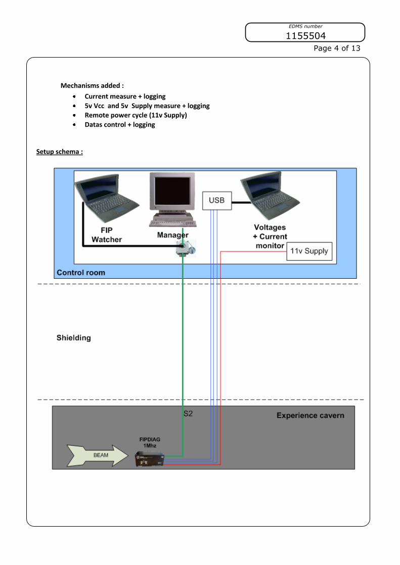
Mechanisms added :
Current measure + logging
5v Vcc and 5v Supply measure + logging
Remote power cycle (11v Supply)
Datas control + logging
Setup schema :
EDMS number
1155504
Page 5 of 13
We processed one run for each card, 3 runs in total. Each card has been placed in order to place the beam like this: DUT a :
DUT b :
Components irradiated : Q1 Si3443
U13 74HCT32D
U17 74HCT123D
U6 MICROFIP
U7 MAX809
XTAL1 40MHz oscillator
Components irradiated : Q1 Si3443
U10 74HCT4040
U8, U11 74HC11D
U13 74HCT32D
U14 LM311D
U18 MC7805ABD2T
XTAL3 32.768kHz oscillator
EDMS number
1155504
Page 6 of 13
DUT c :
FIPDiag back :
Components irradiated : U17 74HCT123D (not all)
U6 MICROFIP
U7 MAX809
NB : The monostable U7 has been disabled for
DUT c (Thanks to Paul’s idea)
EDMS number
1155504
Page 7 of 13
“FIPMobile” :
Schema for the acquisition of current and voltages :
The dose rate is much higher than the one expected in the LHC tunnel. In fact,
lower dose rate values would make the test too long and, therefore unpractical.
One has to note that low dose rate enhances the degradation of analog
components. The test is run up to high dose (a few factor higher than the TID
expected in the LHC tunnel) in order to compensate the enhanced low dose
rate effect.
EDMS number
1155504
Page 10 of 13
6. Observed failure modes
DUT id Failure id Description Recovery mode (reset, power cycle)
a a1 Current consumption goes up to 340mA,
make the 5v voltage down to 3.5v. Ok
after a manual power cycle. Seems like a
SEL on a component.
BEAM DUMP
Reset soft didn’t work
Power cycle OK
a a2 Com lost after a rise of the current.
Several soft reset and power cycles but
the card does not answer anymore. With
a test with a multimeter, the U7 was
blocked and delivered a permanent
reset.
BEAM DUMP
Reset soft didn’t work
Power cycle didn’t work
No recovery
c c1 Com lost during 101cycles (1.5sec) then
ok after the AntiLatchUp power cycle. .
Seems like a SEL on the MicroFIP (or
U17).
AntiLatchUp reset works. We do not
see the current increase but it must
be due to the slow logging
acquisition. The time of the com lost
(1.5sec) match exactly with reset
period, and the Vsupply was on.
c c2 A huge rise of the current drop down the
voltage. We tried to compensate the
drop of the voltage by increasing several
times the 11v supply. Then a lot of data
errors and com lost occurs with the
current at 700mA. At this time we think
that the AntiLatchUp reset doesn’t work
anymore.Looks like total dose effect, it
will be interesting to test it again after a
long rest. (MicroFIP + U17)
BEAM DUMP
Reset soft didn’t work
Power cycle didn’t work
No recovery
7. Test beam results
Run # DUT
id time
Failure(s)
observed
Fluence* since
last recovery
[cm-2]
Total dose
[Gy] comment
1 a 7h40 a1 2E+11 108
1 a 8h02 a2 1.6E+11
108+86 =
194
2 b 10h35 none 6E+11 320
Current has
started to grow
at the end
3 c 11h20 c1 1.7E+11 95
3 c 11h51 c2 4.8E+11 95+159 =
254
EDMS number
1155504
Page 11 of 13
Run1 logging graph :
Run2 logging graph :
EDMS number
1155504
Page 12 of 13
Run3 logging graph :
8. Other observations
To measure current, a resistance of 10 Ohm was on the surface. This choice was not
appropriate because of the unexpected transom, raise of the current observed, that
causes drops in voltage too great and does not guarantee the proper functioning of
the 5V regulator.
9. Conclusions The purpose of these tests was to identify which components of the module FIPDiag
benefit from being replaced for the new card NanoFIPDiag : FIPDiag with the chip NanoFIP in place of MicroFIP, now recognized as sensitive to radiation.
The results are quite good, a component U7 MAX809 has been identified as weak and will be replaced by passive components (see Amelioration fiabilite WorldFip
wfdc001.pdf) in the next design NanoFIPDiag. The MicroFIP held to about 90Gy, mean score but not alarming for a diagnostic
module. However it worked in standalone mode, its mode of operation as simple and with less memory. In addition, given the small number of observed events, it is
difficult to evaluate a cross-section, further testing would be needed in microcontroller mode.