45
3 April 2017 1 Anders J Johansson, Department of Electrical and Information Technology [email protected] RADIO SYSTEMS – ETIN15 Lecture no: 5 Digital modulation

3 April 2017 1
Anders J Johansson, Department of Electrical and Information [email protected]
RADIO SYSTEMS – ETIN15
Lecture no: 5
Digital modulation
3 April 2017 2
Contents
• Brief overview of a wireless communication link• Radio signals and complex notation (again)• Modulation basics• Important modulation formats

3 April 2017 3
STRUCTURE OF A WIRELESSCOMMUNICATION LINK

3 April 2017 4
A simple structure
Speechencoder Encrypt.A/D Chann.
encoding Modulation
Speechdecoder Decrypt.D/A Chann.
decoding Demod.
Key
Speech
Speech
Data
Data
(Read Chapter 10 for more details)

3 April 2017 5
RADIO SIGNALS ANDCOMPLEX NOTATION
(from Lecture 3)

3 April 2017 6
Simple model of a radio signal
• A transmitted radio signal can be written
• By letting the transmitted information change the amplitude, the frequency, or the phase, we get the tree basic types of digital modulation techniques
– ASK (Amplitude Shift Keying)– FSK (Frequency Shift Keying)– PSK (Phase Shift Keying)
Amplitude PhaseFrequency
Constant envelope
REPEATED
FROM LECTURE 3

3 April 2017 7
Example: Amplitude, phase and frequency modulation
4ASK
4PSK
4FSK
cos 2 cs t A t f t t
A t t
00 01 11 00 10
00 01 11 00 10
00 01 11 00 10
- Amplitude carries information- Phase constant (arbitrary)
- Amplitude constant (arbitrary) - Phase carries information
- Amplitude constant (arbitrary)- Phase slope (frequency) carries information
Comment:
REPEATED
FROM LECTURE 3

3 April 2017 8
The IQ modulator
-90o
cf
I-channel
Q-channel
Transmited radio signal
Complex envelope
Take a step into the complex domain:
Carrier factor
(in-phase)
(quadrature)
REPEATED
FROM LECTURE 3

3 April 2017 9
Interpreting the complex notation
Complex envelope (phasor)
Polar coordinates:
Transmitted radio signal
By manipulating the amplitude A(t)and the phase Φ(t) of the complexenvelope (phasor), we can create anytype of modulation/radio signal.
REPEATED
FROM LECTURE 3
3 April 2017 10
MODULATIONBASICS

3 April 2017 11
Complex domain
Pulse amplitude modulation (PAM)The modulation process
Mapping PAMmb mc LPs t
exp 2 cj f t
Re{ }
Radiosignal
PAM:Many possible pulses
“Standard” basis pulse criteria
g t
g t
t
tsT
(energy norm.)
(orthogonality)
Complex numbers
Bits
SymboltimesLPt = ∑
m=−∞
∞
cm g t−mT s
∫−∞
∞
∣g t ∣2dt=1 or =T s
∫−∞
∞
g t g* t−mT s dt=0 for m≠0
3 April 2017 12
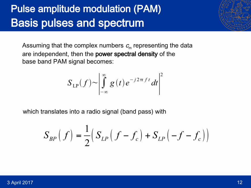
Pulse amplitude modulation (PAM)Basis pulses and spectrum
Assuming that the complex numbers cm representing the dataare independent, then the power spectral density of thebase band PAM signal becomes:
which translates into a radio signal (band pass) with
1
2BP LP c LP cS f S f f S f f
S LP f ~∣∫−∞
∞
g t e− j 2 f t dt∣2

3 April 2017 13
Pulse amplitude modulation (PAM)Basis pulses and spectrum
Illustration of power spectral density of the (complex) base-bandsignal, SLP(f), and the (real) radio signal, SBP(f).
f
LPS f
f
BPS f
cfcf
Symmetry (real radio signal)Can be asymmetric,since it is a complex
signal.
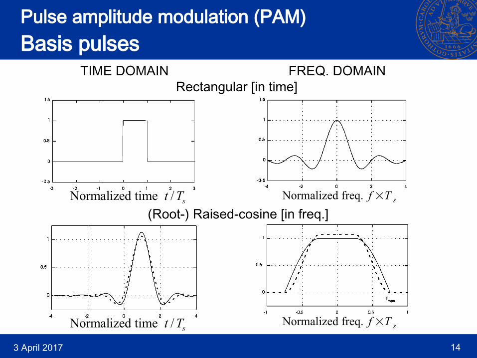
What we need are basis pulses g(t) with nice properties like:
- Narrow spectrum (low side-lobes)
- Relatively short in time (low delay)
3 April 2017 14
Pulse amplitude modulation (PAM)Basis pulses
Normalized time / st T
Normalized time / st T
(Root-) Raised-cosine [in freq.]
Rectangular [in time]TIME DOMAIN FREQ. DOMAIN
Normalized freq. f ×T s
Normalized freq. f ×T s

3 April 2017 15
Pulse amplitude modulation (PAM)Interpretation as IQ-modulator
-90o
cf
ReI LPs t s t
ImQ LPs t s t
cos 2 cf t
sin 2 cf t
Radiosignal
For real valued basis functions g(t) we can view PAM as:
Pulseshaping
filters
g t
g t
Mappingmb mc
Re mc
Im mc
(Both the rectangular and the (root-) raised-cosine pulses are real valued.)
3 April 2017 16
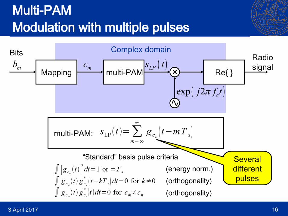
Multi-PAMModulation with multiple pulses
Complex domain
Mapping multi-PAMmb mc LPs t
exp 2 cj f t
Re{ }
Radiosignal
multi-PAM:
Bits
Severaldifferentpulses
“Standard” basis pulse criteria(energy norm.)(orthogonality)
(orthogonality)
sLPt =∑m−∞
∞
g cm t−mT s
∫∣g cm t ∣2dt=1 or =T s
∫ g cm t g cn* t dt=0 for cm≠cn
∫ g cm t g cm*
t−kT s dt=0 for k≠0

3 April 2017 17
Multi-PAMModulation with multiple pulses
and for k = +/- 1, +/- 3, ... , +/- M/2
Frequency-shift keying (FSK) with M (even) different transmissionfrequencies can be interpreted as multi-PAM if the basis functionsare chosen as:
fcfcf
Bits: 00 01 10 11
g k t =e− j k f t for 0≤t≤T s
S LP f S BP f

3 April 2017 18
Continuous-phase FSK (CPFSK)The modulation process
Complex domain
Mapping CPFSKmb mc LPs t
exp 2 cj f t
Re{ }
Radiosignal
Bits
CPFSK:
where the amplitude A is constant and the phase is
where hmod is the modulation index.Phase basis
pulse
CPFSK t =2 hmod ∑m=−∞
∞
cm∫−∞
t
g u−mT du
sLPt =Aexp jCPFSK t

3 April 2017 19
Continuous-phase FSK (CPFSK)The Gaussian phase basis pulse
Normalized time / st T
BTs=0.5
In addition to the rectangular phase basis pulse, the Gaussian is themost common.

3 April 2017 20
IMPORTANT MODULATIONFORMATS

3 April 2017 21
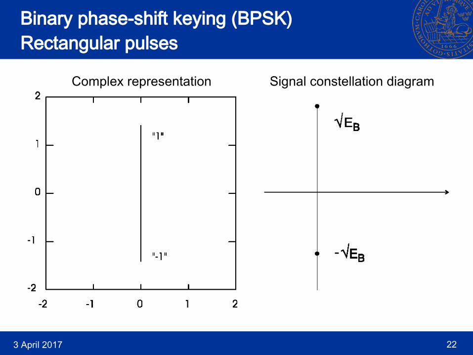
Binary phase-shift keying (BPSK)Rectangular pulses
Radiosignal
Base-band
3 April 2017 22
Binary phase-shift keying (BPSK)Rectangular pulses
Complex representation Signal constellation diagram
3 April 2017 23
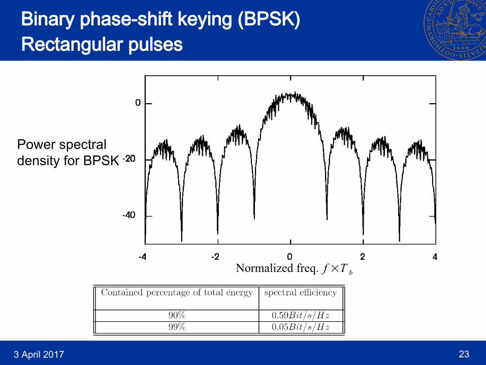
Binary phase-shift keying (BPSK)Rectangular pulses
Power spectraldensity for BPSK
Normalized freq. f ×T b
3 April 2017 24
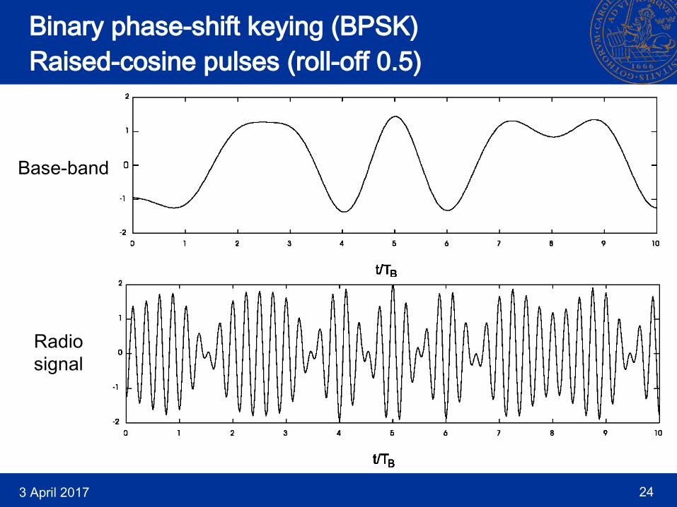
Binary phase-shift keying (BPSK)Raised-cosine pulses (roll-off 0.5)
Base-band
Radiosignal

3 April 2017 25
Binary phase-shift keying (BPSK)Raised-cosine pulses (roll-off 0.5)
Complex representation Signal constellation diagram

3 April 2017 26
Binary phase-shift keying (BPSK)Raised-cosine pulses (roll-off 0.5)
Power spectraldensity for BAM
Much higher spectral efficiency than BPSK
(withrectangular
pulses).
Normalized freq. f ×T b
3 April 2017 27
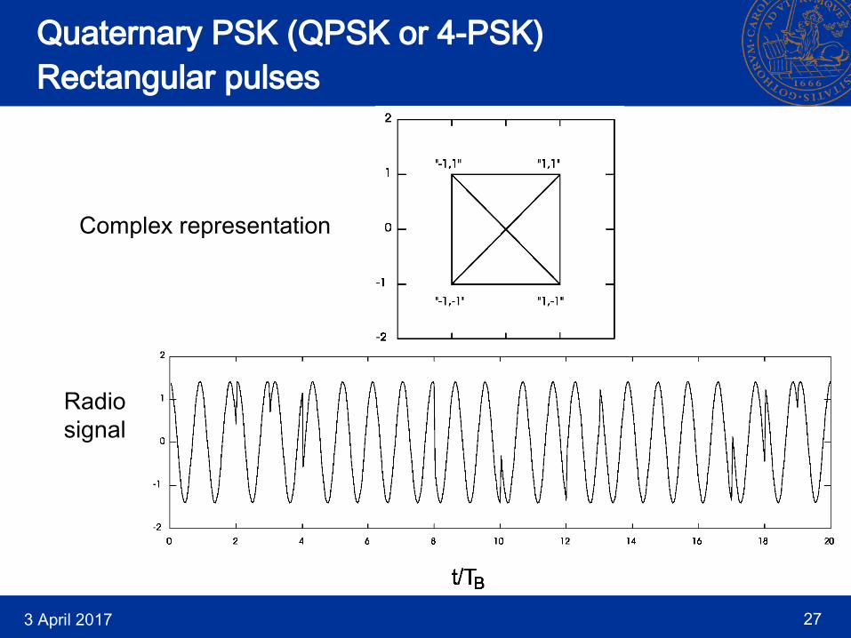
Quaternary PSK (QPSK or 4-PSK)Rectangular pulses
Complex representation
Radiosignal

3 April 2017 28
Quaternary PSK (QPSK or 4-PSK)Rectangular pulses
Power spectraldensity for QPSK
Twice the spectrum efficiency of BPSK (with rect. pulses).
TWO bits/pulseinstead of one.

3 April 2017 29
Quadrature ampl.-modulation (QAM)Root raised-cos pulses (roll-off 0.5)
Complex representation
Much higher spectral efficiency than QPSK
(withrectangular
pulses).
3 April 2017 30
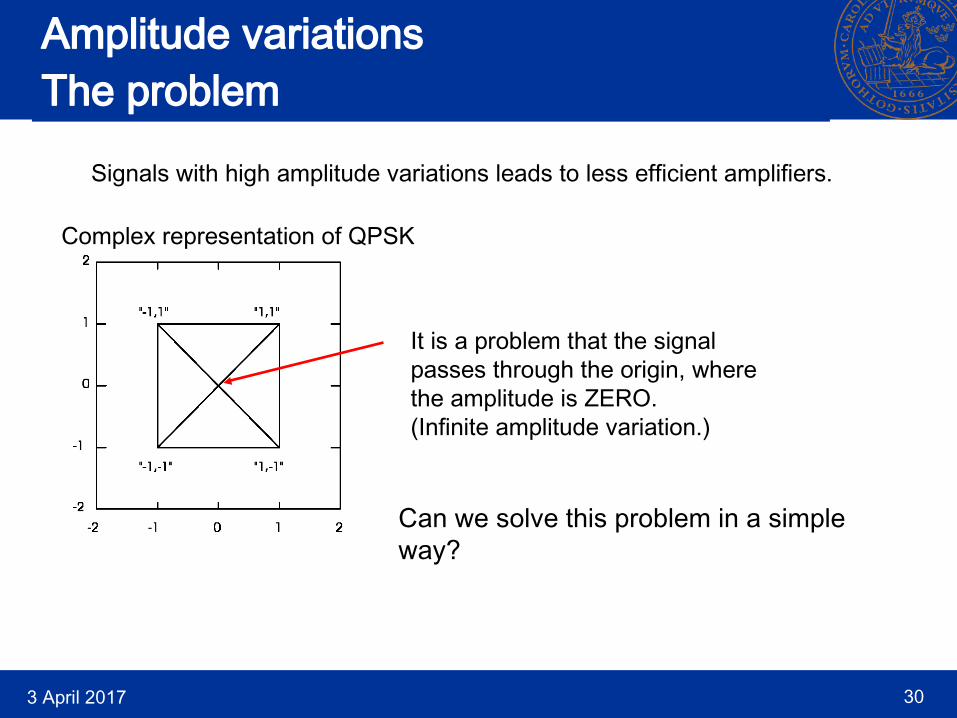
Amplitude variationsThe problem
Signals with high amplitude variations leads to less efficient amplifiers.
Complex representation of QPSK
It is a problem that the signalpasses through the origin, wherethe amplitude is ZERO.(Infinite amplitude variation.)
Can we solve this problem in a simpleway?

3 April 2017 31
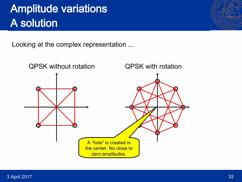
Amplitude variationsA solution
Let’s rotate the signal constellation diagram for eachtransmitted symbol!
/4 2×/4etc.
3 April 2017 32
Amplitude variationsA solution
Looking at the complex representation ...
QPSK without rotation QPSK with rotation
A “hole” is created in the center. No close to
zero amplitudes.

3 April 2017 33
- Differential QPSK (DQPSK)/ 4
Complex representation
Still uses the same rectangular pulses as QPSK - the powerspectral density and the spectral efficiency are the same.
This modulation type is used in several standards for mobilecommunications (due to it’s low amplitude variations).

3 April 2017 34
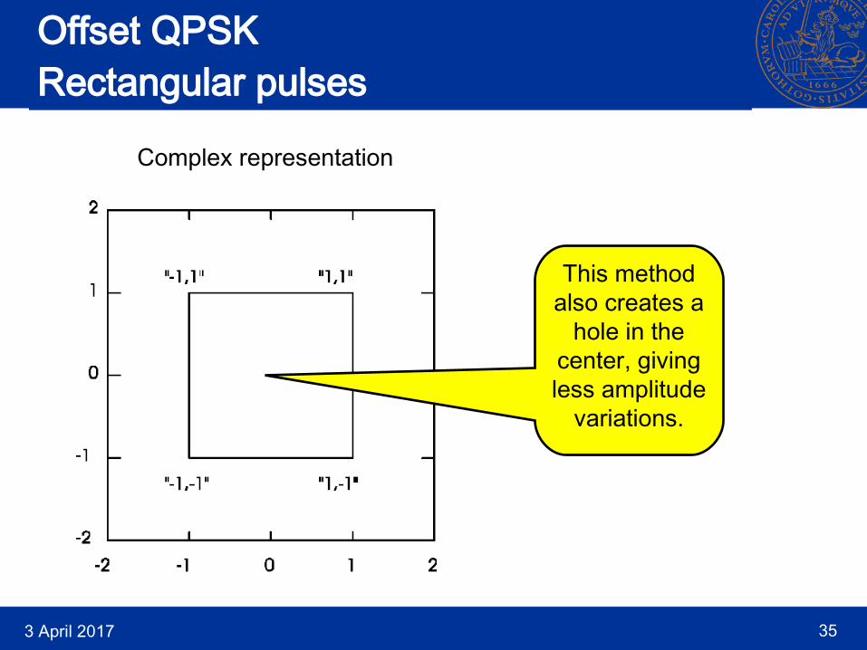
Offset QPSK (OQPSK)Rectangular pulses
In-phasesignal
Quadraturesignal
There is one bit-time offset between the in-pase and the quadraturepart of the signal (a delay on the Q channel). This makes the transitionsbetween pulses take place at different times!
3 April 2017 35
Offset QPSKRectangular pulses
Complex representation
This method also creates a
hole in the center, giving less amplitude
variations.
3 April 2017 36
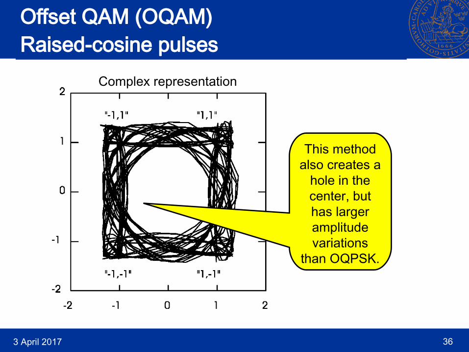
Offset QAM (OQAM)Raised-cosine pulses
Complex representation
This method also creates a
hole in the center, but has larger amplitude variations
than OQPSK.
3 April 2017 37
Phase
32
2
12
−12
−
−32
−2
T b t
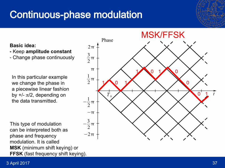
Continuous-phase modulation
Basic idea:- Keep amplitude constant- Change phase continuously
11
1 1
1
0
0 0
0
0
In this particular examplewe change the phase ina piecewise linear fashionby +/- /2, depending onthe data transmitted.
This type of modulationcan be interpreted both as phase and frequencymodulation. It is calledMSK (minimum shift keying) orFFSK (fast frequency shift keying).
MSK/FFSK

3 April 2017 38
Minimum shift keying (MSK)
Simple MSK implementation
Rectangularpulsefilter
01001
0 1 0 0 1
Voltagecontrolledoscillator
(VCO)
MSK signal
3 April 2017 39
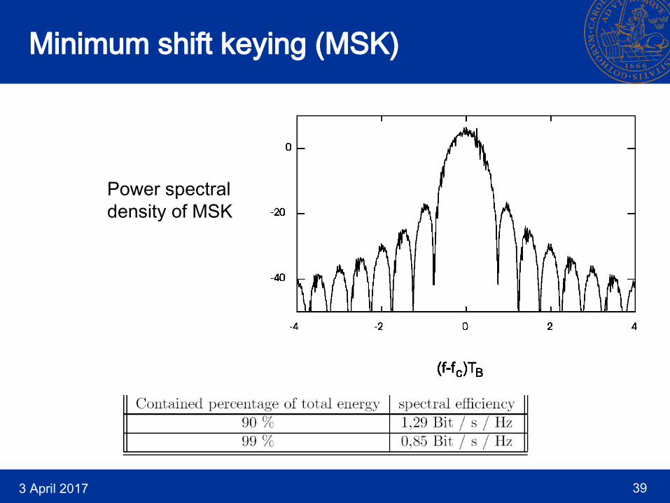
Minimum shift keying (MSK)
Power spectraldensity of MSK

3 April 2017 40
Gaussian filtered MSK (GMSK)
Further improvement of the phase: Remove ’corners’
MSK(Rectangular pulse filter)
Gaussian filtered MSK - GMSK(Gaussian pulse filter)
(Simplified figure)Phase
32
2
12
−12
−
−32
−2
T b t
1 1 1
1 1
1
0 0
0
1 1 1
1 1
1
0 0
0
Phase
32
2
12
−12
−
−32
−2
T b t

3 April 2017 41
Gaussian filtered MSK (GMSK)
Simple GMSK implementation
Gaussianpulsefilter
01001
0 1 0 0 1
Voltagecontrolledoscillator
(VCO)
GMSK signal
When implemented this “simple” way, it is usually called Gaussianfiltered frequency shift keying (GFSK).
GSFK is used in e.g. Bluetooth.

3 April 2017 42
Gaussian filtered MSK (GMSK)
Digital GMSK implementation
-90o
cf
cos 2 cf t
sin 2 cf t
D/A
D/A
Digitalbaseband
GMSKmodulator
Data
AnalogDigital
This is a more precise implementation of GMSK, which is used ine.g. GSM.

3 April 2017 43
Gaussian filtered MSK (GMSK)
Power spectraldensity of GMSK.
BT = 0.5 here(0.3 in GSM)

3 April 2017 44
How do we use all these spectral efficiencies?Example: Assume that we want to use MSK to transmit 50 kbit/sec,
and want to know the required transmission bandwidth.
Take a look at the spectral efficiency table:
The 90% and 99% bandwidths become:
90% 50000 /1.29 38.8 kHzB
99% 50000 / 0.85 58.8 kHzB

3 April 2017 45
Summary
TABLE 11.1 in textbook.
BPSK withroot-raised
cosinepulses


![RADIO SYSTEMS - ETIN15 Lecture no: 12 · PDF fileRADIO SYSTEMS - ETIN15 Lecture no: 12 Wireless LANs/data ... Some WLANs OFDM Data rate [Mbit/sec] Year 1 10 100 0.1 ... Has some similarities](https://static.documents.pub/doc/80x56/5aab31aa7f8b9aa9488bb17c/radio-systems-etin15-lecture-no-12-systems-etin15-lecture-no-12-wireless-lansdata.jpg)


![Interactive Kalman Filtering for Differential and … · coherent demodulation of CPM and CPFSK respectively. In [15], O. Loffeld utilized the EKF in the demodulation of noisy phase](https://static.documents.pub/doc/80x56/5b59e1f17f8b9a88698dfa31/interactive-kalman-filtering-for-differential-and-coherent-demodulation-of-cpm.jpg)


![Eindhoven University of Technology MASTER Een CPFSK demodulator … · is dan ook 3 dB groter [1] dan bij het dual-filtersysteem. De opdracht die mij is toebedeeld, is het ontwikkelen](https://static.documents.pub/doc/80x56/5f3043ffff7e566033796e08/eindhoven-university-of-technology-master-een-cpfsk-demodulator-is-dan-ook-3-db.jpg)
