5
Raising Standards Worldwide GMV Lift Systems www.gmvlifts.co.uk

RaisingStandardsWorldwide
GMV LiftSystems
www.gmvlifts.co.uk

Green Lift GLB MRLTraction Mecatronic The Gearless Belt traction lift has been
developed by our parent company in Sweden to complete our range of lifts. All mounting points are on one load bearing wall to help with the construction of the shaft and reduce installation times. We believe this is one of the best MRL traction lifts on the market.
GLB MRL Advantages
•Superiorridequalityandfloorlevelling precision
•Quietrideandlownoisetransmission•Reliableinservice
Reliable Technology
•Safesystemwhichiseasytoinstalland keep efficient
•GearlessBeltmachineespeciallydesigned for machine room-less applications
•VVVFdrive,fieldorientedvectorcontrol with sinus encoder
•Electricalabsorption11.5A(630kg)
CostEffective
•Lowinstallationcost•Lowmaintenancecostsandeasily
accessible spare parts•Reducedenergyconsumptionin
comparison with a traditional geared machine
Flexible
•Lowforcesonshaftwalldueto GLB MRL machine being installed on
top of the guide rail•Whenusingareinforcedguiderail,
thebracketscanbefixedineachfloorslab
•LandingdoorsandTMCcaravailablein a wide range of colours or stainless steel
•Electricalcontrolpaneltobelocatedeitheroutsideorinsidetheshaft(inthelattercase,remotecontrolsonthehighestfloordoorwillenableinspection,maintenanceandemergencyoperations)
Safe
•Automaticreturntolandingincaseof power failure
•ManualrescueoperationmadebyUPS
GoodsPassengerandVehicle LiftsHydro Fluitronic
GPL25,GPL40,GPL40FOur goods lifts are the jewel in GMV’s crown. We can provide goods and vehicle lifts to suit most applications – our standard lift packages range upto8000kgwhilethepossibilitiesforbespoke lifts are far reaching.
GPL80F
•Flexibledesignswhichcanbetailored to comply with most specifications
•Liftdesignedforforkliftloading
Reliability in Service
•Robustanddurablecardesign•Doorsillsdesignedforforklifttruck
loading
Flexible
•Modulardesignwhichfulfilsdifferentcustomers’requirementsregardingrated load and car dimensions
•Thecarframeandjackdesignresultin minimum shaft dimensions in relation to the car size
Safe
•TypeapprovedaccordingtoLiftDirective95/16/EC
•Tankunitandcontrollerareplacedina service friendly machine room
•Automaticreturntolandingincaseofpowerfailure(option)
CostEffective
•Componentspreparedforaquickand easy installation
•LowserviceandmaintenancecostsduetohighqualityGMVcomponents
GPL25,GPL40,GPL40F,GPL80F, VL
GPL80F
Pag
e2
Pag
e3

GLFMRL-T GLFMRL-MCGreen Lift Fluitronic Green Lift Fluitronic
GLFMRL-T*OurMRL-T(Tower)hydraulic,whichfeatures a tower shaped tank located inthepit,eliminatestheneedforamachine room or landing mounted cabinet. This option is great for when space is precious but the cost saving benefitsofahydraulicliftarerequired.
All the advantages of an MRL without compromisingsafetyrequirements!
Technologically Advanced
•Electronicvalveprovides: - high ride performance with gradual
and undetected acceleration and deceleration,andaccuratefloorlevelling with no vibration
-reductioninpowerrequirements•Softstarteravailabletoreduceinitial
current•Greatlyreducednoiselevels•Eco-fluidsormineraloilcanbeused
Flexible
•Carcanbe“finished”tothecustomer’schoiceincluding:
- a wide range of elegant wall panels - easy assembly•Reducedoverallshaftdimensions
GLFMRL-MCThis lift benefits from an MRL–MC (machinerycabinet)situatedonthe landing rather than in the pit or machineroom,thismakesservicingsafe and easy for the engineers. The installation remains simple as the programming of the controller can be done from the landing rather than within the shaft.
SimpleandInexpensive
•Nomachineroom•CompetitivelypricedwithotherMRL
lifts on the market•Reducedmaintenancecostsand
easily accessible spare parts•Quickandeasyassemblyand
installation
Safe
•Accesstohandpump,manuallowering button and controller diagnostics from outside the shaft
•Emergencyoperationofmanuallowering in a very short time by non- specialised but properly trained users
GLFMRL-T** (reducedpitandoverhead)A Green Lift MRL with reduced pit andoverheadrequirements,idealforinstallationinexistingbuildings
Flexible
•Reducedpitandoverheadrequirementscomparedtotraditional lifts
GLFMRL-MC* (reducedpitandoverhead)A Green Lift MRL with reduced pit andoverheadrequirements,idealforinstallationinexistingbuildings
Flexible
•Reducedpitandoverheadrequirementscomparedtotraditional lifts
•Flexiblemachinerycabinetlocation,occupyingonly0.3m²,housing the controller and power unit
SimpleandInexpensive
•Lowmaintenancecostsandeasilyaccessible spare parts
GLFMRL-Twith reduced pit and overhead option
GLFMRL-MCwith reduced pit and overhead option
Green Lift Fluitronic Green Lift Fluitronic
*ThisliftconformstoLiftDirective95/16/ECandissubjecttotheprescriptionsofAnnexI,art.2.2ofthesaidDirectiveandreferstoEN81.21forinstallationinexistingbuildings.**ThisliftmodelconformstoLiftDirective95/16/ECandissubjecttotheprescriptionsofAnnexI,art.2.2ofthesaidDirectiveandreferstoEN81.21forinstallationinexistingbuildingsandtoEN81.2:1999/A2:2004rulesforinstallationwithoutamachineroom. *ThisliftconformstoLiftDirective95/16/ECandissubjecttothe
prescriptionsofAnnexI,art.2.2ofthesaidDirectiveandreferstoEN81.21forinstallationinexistingbuildings.
Pag
e4
Pag
e5
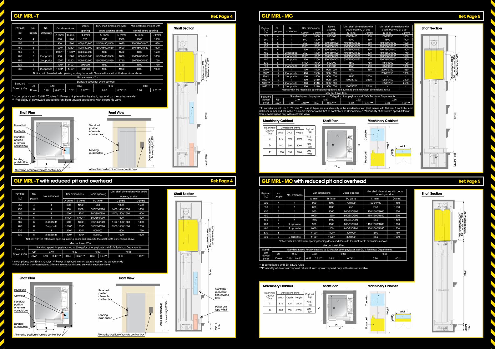
Payload
[kg]
No.
people
No.
entrances
Car dimensionsDoors
opening
Min. shaft dimensions with
doors opening at side
Min. shaft dimensions with
central doors opening
A (mm) B (mm) PL (mm) C (mm) D (mm) C (mm) D (mm)
350 4 1 800 1200 750 1330 1550 1600 1550
450 6 1 950 1300 800/850/900 1450/1480/1550 1630 1750/1800/1900 1630
450 6 1 1000* 1250* 800/850/900 1500/1500/1550 1600 1500/1500/1550 1600
450 6 1 1100** 1100** 800/850/900 1600 1500 1600 1500
480 6 2 opposite 950 1300 800/850/900 1450/1480/1550 1800 1450/1480/1550 1800
480 6 2 opposite 1000* 1250* 800/850/900 1500/1500/1550 1750 1500/1500/1550 1750
630 8 1 1100* 1400* 800/900 1600 1750 1600 1750
630 8 2 opposite 1100* 1400* 800/900 1600 1900 1600 1900
Notice: with fire-rated side opening landing doors add 30mm to the shaft width dimensions above
Max car travel 17m
Standard
Speed (m/s)
Standard speed for every payload
Up 0.40 0.52 0.62 0.86
Down 0.40 0.48*** 0.52 0.62*** 0.62 0.74*** 0.86 1.00***
* In compliance with EN 81.70 rules ** Power unit placed in the shaft, rear wall on the carframe side***Possibility of downward speed different from upward speed only with electronic valve
GLFMRL-T
GLFMRL-Twith reduced pit and overhead
GLFMRL-MC
GLFMRL-MCwith reduced pit and overhead
Ref:Page4
Ref:Page4
Ref:Page5
Ref:Page5
Payload
[kg]
No.
peopleNo. entrances
Car dimensions Doors openingMin. shaft dimensions with doors
opening at side
A (mm) B (mm) PL (mm) C (mm) D (mm)
350 4 1 800 1200 750 1330 1550
450 6 1 950 1300 800/850/900 1450/1480/1550 1630
450 6 1 1000* 1250* 800/850/900 1500/1500/1550 1600
450 6 1 1100** 1100** 800/850/900 1600 1500
480 6 2 opposite 950 1300 800/850/900 1450/1480/1550 1800
480 6 2 opposite 1000* 1250* 800/850/900 1500/1500/1550 1750
630 8 1 1100* 1400* 800/900 1600 1750
630 8 2 opposite 1100* 1400* 800/900 1600 1900
Notice: with fire-rated side opening landing doors add 30mm to the shaft width dimensions above
Max car travel 17m
Standard
Speed (m/s)
Standard speed for payloads up to 630kg (for other payloads call GMV Techincal Department)
Up 0.40 0.52 0.62 0.86
Down 0.40 0.48*** 0.52 0.62*** 0.62 0.74** 0.86 1.00**
* In compliance with EN 81.70 rules ** Power unit placed in the shaft, rear wall on the carframe side***Possibility of downward speed different from upward speed only with electronic valve
Payload [kg]
No. people
No. entrances
Car dimensionsDoors
openingMin. shaft dimensions with
doors opening at sideMin. shaft dimensions with
doors opening at sideA (mm) B (mm) PL (mm) C (mm) D (mm) C (mm) D (mm)
320 4 1 900 1000 700/800 1330/1400 1350 1550/1750 1300350 4 1 800 1200 750 1350 1550 1600 1500450 6 1 950 1300 800/850/900 1400/1500/1550 1650 1750/1800/1900 1600450 6 1 1000* 1250* 800/850/900 1450/1500/1550 1600 1720/1800/1900 1550450 6 1 1100 1100 800/850/900 1530/1550/1550 1450 1750/1850/1900 1400480 6 2 opposite 950 1300 800/850/900 1400/1500/1550 1800 1750/1850/1900 1740480 6 2 opposite 1000* 1250* 800/850/900 1400/1500/1550 1750 1720/1800/1900 1690480 6 2 opposite 1100 1100 800/850/900 1530/1550/1550 1600 1750/1850/1900 1550630 8 1 1100* 1400* 800/900 1550 1750 1750/1900 1700630 8 2 opposite 1100* 1400* 800/900 1550 1900 1750/1900 1850
900** 12 1 1400 1500 900/1000 1850 1850 2000/2150 1850900** 12 2 opposite 1400 1500 900/1000 - - 2000/2150 1950920** 12 2 opposite 1400 1500 900/1000 1850 2000 - -1000** 13 1 1100 2110 900/1000 1600/1700 2450 1950/2150 24201000** 13 2 opposite 1100 2110 900/1000 - - 1950/2150 25501025** 13 2 opposite 1100 2110 900/1000 1600/1700 2610 - -
Notice: with fire-rated side opening landing doors add 30mm to the shaft width dimensions aboveMax car travel 17m
Standard Speed (m/s)
Standard speed for payloads up to 630kg (for other payloads call GMV Techincal Department)Up 0.40 0.52 0.62 0.86
Down 0.40 0.48*** 0.52 0.62*** 0.62 0.74*** 0.86 1.00***
* In compliance with EN 81.70 rules **These lift types are available only in the standard version (that means with Setronik 1 controller and 8700 car frame) and not in the “Fluitronic version” (with GMV 10 controller and Union frame) ***Possibility of downward speed different from upward speed only with electronic valve.
MachineryCabinet
Type
Dimensions (mm)Payload
(kg)Width Depth Height
C 870 400 2100320 -630
D 780 350 2060320 - 630
F 1000 650 2100900 -1025
ShaftPlan
Power Unit Standard position of remote controls box
Landing push-button
Alternative position of remote controls box
Controller
Standard positionof remotecontrols box
Landing push button
Alternative position of remote controls box
PLC
D
ShaftPlan
ShaftPlan
Machinery Cabinet
Machinery Cabinet
FrontView
ShaftPlan
Machinery Cabinet
Machinery Cabinet
FrontView
Shaft Section Shaft Section
Shaft SectionShaft Section Payload [kg]
No. people
No. entrancesCar dimensions Doors opening
Min. shaft dimensions with doors opening at side
A (mm) B (mm) PL (mm) C (mm) D (mm)
320 4 1 900 1000 700/800 1330/1400 1450
350 4 1 800 1200 750 1350 1550
450 6 1 950 1300 800/850/900 1400/1500/1600 1650
450 6 1 1000* 1250* 800/850/900 1450/1500/1550 1600
450 6 1 1100 1100 800/850/900 1550 1450
480 6 2 opposite 950 1300 800/850/900 1400/1500/1600 1800
480 6 2 opposite 1000* 1250* 800/850/900 1400/1500/1550 1750
630 8 1 1100* 1400* 800/900 1550 1750
630 8 2 opposite 1100* 1400* 800/900 1550 1900
Notice: with fire-rated side opening landing doors add 30mm to the shaft width dimensions above
Max car travel 17m
Stand-ard
Speed (m/s)
Standard speed for payloads up to 630kg (for other payloads call GMV Techincal Department)
Up 0.40 0.52 0.62 0.86
Down 0.40 0.48** 0.52 0.62** 0.62 0.74** 0.86 1.00**
* In compliance with EN 81.70 rules**Possibility of downward speed different from upward speed only with electronic valve
MachineryCabinet
Type
Dimensions (mm)Payload
(kg)Width Depth Height
C 870 400 2100320 - 630
D 780 350 2060320 -630
Fra
mes
hei
ght
222
5D
oors
op
enin
g 2
000
Tra
vel
Tra
vel
Tra
vel
Tra
vel
Min
hea
dro
om 2
000
Min
hea
dro
om 2
000
Min
hea
dro
om 2
000
Min
hea
dro
om 2
000
Controller placed at first serviced level
Power unit type MRL-T
Min
hea
dro
om 2
250
Min
hea
dro
om 2
250
Min
hea
dro
om 2
225
Min
hea
dro
om 2
225
Min
hea
dro
om 2
750
Min
hea
dro
om 3
400
Min
hea
dro
om 2
750
Min
hea
dro
om 2
750
Min
Pit
1100
Min
Pit
1100
Min
Pit
450
Width
Width
Dep
thD
epth
Hei
ght
Hei
ght
Pow
er U
nit
Pow
er U
nit
Con
trolle
rC
ontro
ller
D
D
BB
A
A
PL
PL
C
CMin
Pit
1100
Standard position of remote controls box
Landing push-button
Alternative position of remote controls box
Fra
mes
hei
ght
222
5
Doo
rs o
pen
ing
200
0
Power Unit
Controller
Standard positionof remotecontrols box
Landing push button
Alternative position of remote controls box
PLC
D

GLB MRL
GPL25,GPL40,GPL40F,GPL80F, VL F=DesignedforforkliftloadingVL=VehicleLift
Ref:Page3
Ref:Page2
Payload [kg]
No. people
Nominal current
[A]
Output power [kW]
No. entrances
Car dimensions Doors openingMin. shaft dimensions with
doors opening at side
A (mm) B (mm) PL (mm) C (mm) D (mm)
450 68.7 2.8
1 950 1300 800/850/900 1500/1500/1550 1650
450 6 1 1000 1250 800/850/900 1500/1500/1550 1600
480 68.9 3
2 opposite 950 1300 800/850/900 1500/1500/1550 1840
480 6 2 opposite 1000 1250 800/850/900 1500/1500/1550 1790
630 89.5 4
1 1100 1400 800/900 1600 1750
630 8 2 opposite 1100 1400 800/900 1600 1940
1000 1015.5 6.5
1 1100 2110 800/900 1600 2500
1000 10 2 opposite 1100 2110 800/900 1600 2610
Speed 1 m/s – Travel max 31 m
Up to 11 stops and 12 services
Motive force (upstream the inverter) 230/400 Volt a.c. – 50 - 60 Hz
Lift Type
Rated Load Kg
Car area m²
Car Width
CW mm
Car Depth
CD mm
No. of Jacks
Car height
CH mm
Shaft width
SW mm
Door width
DW mm
Shaft width SW min at 4 panel door
Shaft width SW min at 6 panel door
Door height
DH mm
GPL 25
1500 – 2500
<4.851200 – 1700
1700 – 3950
2
2200
– 2
600
CW
+ 7
00 –
130
0
Opt
iona
l DW
= (
CW
– 1
00)
mm
, max
300
0mm
1.5
x C
W +
200
mm
1.35
x C
W +
200
mm
2000
– 2
500GPL
402500 – 4000
<7.151700 – 2700
1700 – 4200
2
GPL 40 F
2500 – 4000
<7.041700 – 3200
1700 – 4100
2
GPL 80F
4000 – 8000
<13.51700 – 2900
3000 – 6000
4
VL 3800 13.44 2400 5600 2
Max Speed 0.63 m/sec
Max car travel 20 m
Tel.: +44 (0) 1924 566 350Fax: +44 (0) 1924 229 230
e-mail: [email protected]
GMV UK LTD, 1 Mariner Court, Calder ParkWakefield, WF4 3FL, United Kingdom
UNI EN ISO 9001Certified Company
GPL25,40,40F GPL80F
ShaftPlan
Shaft Section
Shaft Section
CD
SDCD
SD
CWSW
CWSW
Pit d
epth
PD
min
. 100
0mm
Hea
d ro
om H
Rm
in. 3
400
mm
min
. 340
0 m
m
E E
Ma
x tra
vel.
31.0
00 m
mm
in. 1
100
mm
A
D
B
PL
C


