10
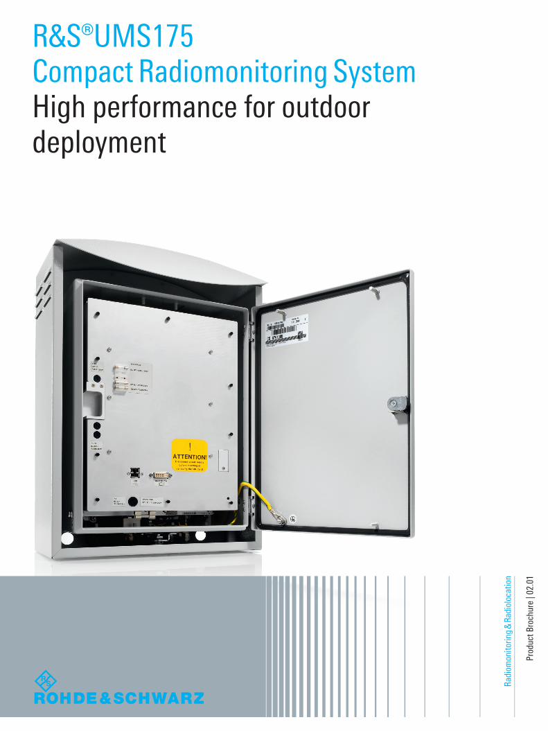
Radiomonitoring & Radiolocation Product Brochure | 02.01 R&S®UMS175 Compact Radiomonitoring System High performance for outdoor deployment
Radi
omon
itorin
g &
Radi
oloc
atio
n
Prod
uct B
roch
ure
| 02.
01
R&S®UMS175Compact Radiomonitoring SystemHigh performance for outdoor deployment
UMS175_bro_en_3607-1488-12_v0201.indd 1 11.02.2016 09:50:15

2
R&S®UMS175 Compact Radiomonitoring SystemAt a glanceThe R&S®UMS175 combines state-of-the-art receiver technology with flexible communications capabilities and a control PC in a compact all-weather cabinet. The result is an extremely powerful and versatile outdoor system for radiomonitoring and emitter location based on measuring the time difference of arrival (TDOA).
As a receiver within a TDOA network, it delivers I/Q sam-ples for high-precision location missions. High system sensitivity and an integrated preselection filter make the system ideal for deployment in difficult signaling environ-ments. The system’s minimum infrastructure requirements and highly flexible remote control capabilities make select-ing an operating site easy.
Two tried-and-tested software packages – R&S®ARGUS for spectrum monitoring and R&S®RAMON for com-munications intelligence (COMINT) – are available for the R&S®UMS175. This software also allows quick and easy integration of the R&S®UMS175 into existing radiomonitoring systems. The use of open interfaces in the hardware and operating system makes it possible for cus-tomers and system integrators to develop their own soft-ware applications. The R&S®UMS175 is the ideal system for a very broad range of monitoring and location tasks.
Key facts ❙ Complete radiomonitoring system in a compact, all-weather cabinet suitable for outdoor use
❙ Emitter location based on TDOA ❙ Wide frequency range from 9 kHz to 7.5 GHz ❙ Open interfaces ❙ High system sensitivity
All ports are located on the bottom of the system for weather
protection. (This photo shows the system with the optional
all-weather cabinet).
This system's outstanding RF characteristics make it possible to monitor wideband signals and reliably detect short-duration signals and frequency agile transmitters.
UMS175_bro_en_3607-1488-12_v0201.indd 2 11.02.2016 09:50:18

Rohde & Schwarz R&S®UMS175 Compact Radiomonitoring System 3
R&S®UMS175 Compact Radiomonitoring SystemBenefits and key features
Integrated latest-generation monitoring receiver from Rohde & Schwarz ❙ Wide frequency range from 9 kHz to 7.5 GHz for monitoring signals previously not detectable by classical receivers
❙ Extremely high scanning speed and digital signal processing for detecting frequency agile signals and bursts (short-duration transmissions)
❙ Integrated preselection for operating the R&S®UMS175 in the vicinity of powerful transmitters
❙ 10 MHz realtime bandwidth for monitoring wideband signals
❙ High system sensitivity for detecting even very weak signals
Well-suited for diverse missions ❙ Geolocation via TDOA ❙ Autonomous long-term operation ❙ Detecting interference
Use in different radiomonitoring applications ❙ Spectrum monitoring using the optional R&S®ARGUS software
❙ COMINT using the optional R&S®RAMON software ❙ Customer-specific software applications made possible by the system's open interfaces
Integrated powering and control of external components ❙ Powering of active antennas via optional DC feeds ❙ Control of external components, such as RF relays, via switching outputs
Flexible operating concept ❙ Remote control via LAN/WAN or mobile radio networks (GSM/UMTS/LTE)
❙ Local operation, especially for system configuration and integration
❙ Full access to internal control PC and receiver ❙ Integrated router for more security and flexibility
Easy selection of operating sites due to minimum infrastructure requirements ❙ Compact dimensions ❙ Flexible power supply concept (AC and DC, can be applied simultaneously)
❙ Remote control via LAN/WAN or mobile communications networks
❙ Low power consumption
UMS175_bro_en_3607-1488-12_v0201.indd 3 11.02.2016 09:50:18

MainboardPCI
LAN
USB
Audio
Encl
osur
e he
atin
g
Wire
less
mod
ule
(opt
iona
l)
Communicationsantenna
X30
Monitoringreceiver
X20 X21Monitoringantennas
X50 X41AUX1GPS
antennaEthernet
X10
Processormodule
USBVGA
DC OUT1X40
Power supply
DC
AC
DC INX2
AC INX1
Statussignaling
On/off
Rout
er
4
The optional all-weather cabinet (R&S®UMS12-B1) protects the radiomonitoring system against external mechanical impacts, expanding the range of applications for outdoor deployment.
The R&S®UMS175-B5 option enables remote control of the R&S®UMS175 over a GSM, UMTS (3G) or LTE network. The integrated router provides a high level of security. Features like VPN tunnels, encryption and firewall rules minimize the risk of unauthorized access. Further-more, it assures great flexibility for easy utilization of ex-isting communications infrastructures. There are hardly any limitations when selecting an operating site for the R&S®UMS175.
Active antennas can be powered directly from the R&S®UMS175 using optional external DC feeds. It is also possible to control external components such as RF relays. Moreover, receiver options such as a frequency extension up to 7.5 GHz or high-speed scanning are available.
When controlling the R&S®UMS175 via R&S®ARGUS, it makes sense to use the R&S®UMS17-SWB option, which allows highly efficient receiver operation as well as switch-ing of the antenna inputs. Other R&S®ARGUS options are available to accommodate changing requirements, including measurement modes and open interfaces. This makes it easy to integrate the R&S®UMS175 into existing radiomonitoring systems.
System configurationThe R&S®UMS175 base unit includes a receiver, a con-trol PC, router, LAN and a power supply. All components are integrated in the inner enclosure. Two antenna in-puts are connected to the receiver via a switch. The inte-grated heating system makes it possible to operate the R&S®UMS175 outdoors even when temperatures are very low.
The control PC (with a Windows 7 Embedded operating system), the receiver, the antenna switch and all interfaces are freely accessible and well documented, allowing customers and system integrators to generate custom application software simply and reliably and meet special requirements.
All the components needed to set up and operate the sys-tem (power cables and mounting materials) are included.
System configuration
UMS175_bro_en_3607-1488-12_v0201.indd 4 11.02.2016 09:50:18

Rohde & Schwarz R&S®UMS175 Compact Radiomonitoring System 5
Operation Interactive operationIn interactive mode, measured values, including the IF spectrum and demodulated audio signals, are sent as a realtime data stream to the control application in the con-trol center and displayed as a table and/or graphic. Users can evaluate the data and, if necessary, initiate action.
Automatic operationIn automatic mode, measurement tasks are sent to the R&S®UMS175, which processes them automatically. This mode is used, for example, for measurements that only cover a specific time period, or to compare current mea-surement values with user-defined reference values. This makes it possible to detect sources of interference and illegal transmitters as well as unauthorized emissions from licensed transmitters. When activity is detected on an unassigned frequency, the R&S®UMS175 can imme-diately analyze the transmitter in greater detail, activate direction finding networks and collect all the information that allows the transmitter to be identified and localized. In automatic mode, different measurements can be made quasi-simultaneously.
Local operationIt is also possible to operate the R&S®UMS175 locally. Opening the door to the inner enclosure provides access to the VGA and USB ports for connecting a keyboard, mouse and monitor. This makes it easy to integrate the R&S®UMS175 into vehicles, for example. Local operation is particularly useful for system integration and configura-tion and for developing custom software applications.
Several software solutions are available for controlling the R&S®UMS175. The receiver control software is included in the R&S®UMS175 base unit. If the R&S®UMS175 is used as a local or remote sensor in COMINT/CESM applica-tions, the R&S®RAMON system software is recommended for most efficient operation. The R&S®ARGUS standard software for ITU-compliant monitoring offers impressive capabilities for spectrum monitoring with a wide range of functions and user-friendly operation. Furthermore, open, well-documented interfaces make it possible to develop custom software applications.
Remote controlThe R&S®UMS175 is primarily designed for remote opera-tion. Working from the control center, operators typically define and control measurements using the appropriate R&S®UMS175 remote control software. Communications between the control center and the R&S®UMS175 take place either via LAN/WAN or mobile communications links. Pre-configured (default) network configurations and the untilization of DHCP server make deployment very fast and efficient. In the case of GSM links, the R&S®UMS175's output data rate can be significantly high-er than the available network bandwidth. In such cases, the Rohde & Schwarz control software ensures optimal uti-lization of the available data rate. Measurements are per-formed interactively or fully automatically, depending on the specific task.
IF spectrum and waterfall display for a radar signal using R&S®EM100-Control.
UMS175_bro_en_3607-1488-12_v0201.indd 5 11.02.2016 09:50:19
6
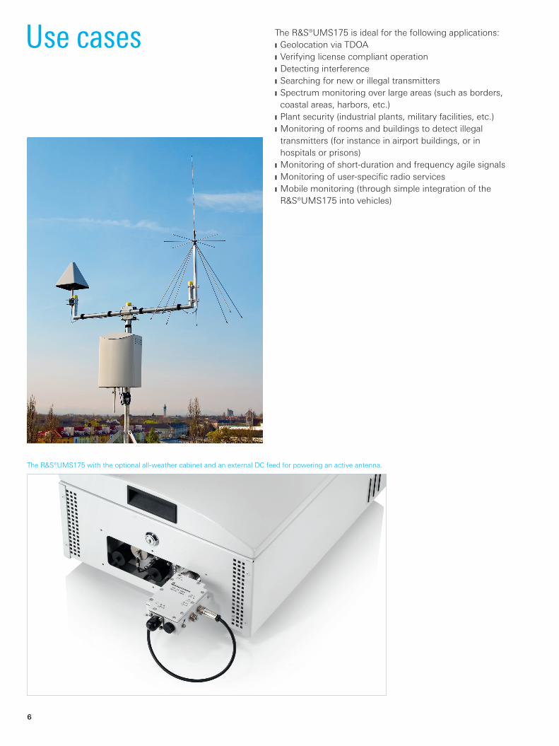
The R&S®UMS175 is ideal for the following applications: ❙ Geolocation via TDOA ❙ Verifying license compliant operation ❙ Detecting interference ❙ Searching for new or illegal transmitters ❙ Spectrum monitoring over large areas (such as borders, coastal areas, harbors, etc.)
❙ Plant security (industrial plants, military facilities, etc.) ❙ Monitoring of rooms and buildings to detect illegal transmitters (for instance in airport buildings, or in hospitals or prisons)
❙ Monitoring of short-duration and frequency agile signals ❙ Monitoring of user-specifi c radio services ❙ Mobile monitoring (through simple integration of the R&S®UMS175 into vehicles)
Use cases
The R&S®UMS175 with the optional all-weather cabinet and an external DC feed for powering an active antenna.
UMS175_bro_en_3607-1488-12_v0201.indd 6 11.02.2016 09:50:22
Rohde & Schwarz R&S®UMS175 Compact Radiomonitoring System 7
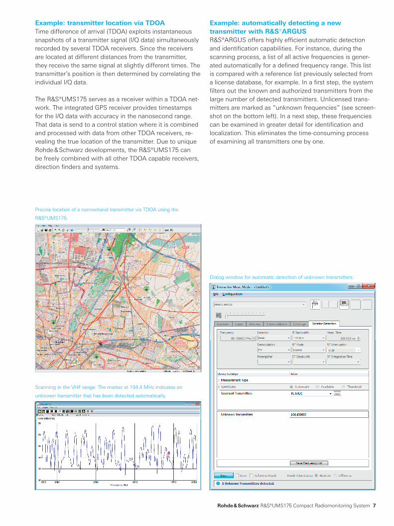
Example: automatically detecting a new transmitter with R&S®ARGUSR&S®ARGUS offers highly efficient automatic detection and identification capabilities. For instance, during the scanning process, a list of all active frequencies is gener-ated automatically for a defined frequency range. This list is compared with a reference list previously selected from a license database, for example. In a first step, the system filters out the known and authorized transmitters from the large number of detected transmitters. Unlicensed trans-mitters are marked as “unknown frequencies” (see screen-shot on the bottom left). In a next step, these frequencies can be examined in greater detail for identification and localization. This eliminates the time-consuming process of examining all transmitters one by one.
Example: transmitter location via TDOATime difference of arrival (TDOA) exploits instantaneous snapshots of a transmitter signal (I/Q data) simultaneously recorded by several TDOA receivers. Since the receivers are located at different distances from the transmitter, they receive the same signal at slightly different times. The transmitter’s position is then determined by correlating the individual I/Q data.
The R&S®UMS175 serves as a receiver within a TDOA net-work. The integrated GPS receiver provides timestamps for the I/Q data with accuracy in the nanosecond range. That data is send to a control station where it is combined and processed with data from other TDOA receivers, re-vealing the true location of the transmitter. Due to unique Rohde & Schwarz developments, the R&S®UMS175 can be freely combined with all other TDOA capable receivers, direction finders and systems.
Scanning in the VHF range: The marker at 104.4 MHz indicates an
unknown transmitter that has been detected automatically.
Dialog window for automatic detection of unknown transmitters.
Precise location of a narrowband transmitter via TDOA using the
R&S®UMS175.
UMS175_bro_en_3607-1488-12_v0201.indd 7 11.02.2016 09:50:22

Rohde & Schwarz R&S®UMS175 Compact Radiomonitoring System 8
SpecificationsReceiver data
Frequency range base unit 9 kHz to 3.5 GHz
with R&S®UMS20-FE option 9 kHz to 7.5 GHz
Scan speed with R&S®UMS20-PS option up to 1.8 GHz/s
IF spectrum display range 1 kHz to 10 MHz (1/2/5/10/20/50/100/200/500 kHz, 1/2/5/10 MHz)
Display modes normal (clear/write), average, max. hold, min. hold
Preselection included
Demodulation AM, FM, USB, LSB, ISB, pulse, CW, I/Q
Interfaces
External
DC voltage input 7-contact circular connector
AC voltage input 4-contact circular connector
LAN 1 Gbit Ethernet, RJ-45 female
DC voltage output 24 V DC, max. 500 mA, 5-contact circular connector with two open-drain drivers
Communications antenna N female, 50 Ω 1)
Monitoring inputs N female, 50 Ω, 9 kHz to 7.5 GHz, 0 V DC; two inputs with internal switch (SPDT)
GPS antenna SMA female, 50 Ω
Internal (after opening the lockable door)
Monitor VGA female
USB 2 × USB female, type A, USB 2.0
SIM card mini-SIM 1.8/3 V 1)
General data
Power supply 100 V to 240 V AC, 50 Hz to 60 Hz, max. 200 VA
12 V to 30 V DC, max. 125 W
Operating temperature range, without direct sunlight
base unit –30 °C to +40 °C
with all-weather cabinet 2) –30 °C to +50 °C
Storage temperature range –30 °C to +70 °C
Degree of protection base unit IP54
with all-weather cabinet 2) IP55
Relative humidity 95 % cyclic test, at +25 °C/+40 °C
Shock in line with EN 60068-2-27, MIL-STD-810E, method 516.4, procedure 1
Vibration sinusoidal in line with EN 60068-2-6
random in line with EN 60068-2-64
Electromagnetic compatibility (EMC) in line with EN 55022, ETSI EN 301489-1, ETSI EN 301489-22
Dimensions (W × H × D) base unit 300 mm × 445 mm × 175 mm(11.81 in × 17.52 in × 6.89 in)
with all-weather cabinet 2) 380 mm × 530 mm × 240 mm(14.96 in × 20.87 in × 9.45 in)
Weight base unit 8 kg (17.64 lb)
with all-weather cabinet 2) 12 kg (26.46 lb)
1) Requires R&S®UMS175-B5 option.2) R&S®UMS12-B1 option.
Specifications
UMS175_bro_en_3607-1488-12_v0201.indd 8 11.02.2016 09:50:22

Rohde & Schwarz R&S®UMS175 Compact Radiomonitoring System 9
Ordering informationDesignation Type Order No.Compact Radiomonitoring System The base unit includes the inner enclosure with an RF module (9 kHz to 3.5 GHz), ), a GPS receiver, a control PC, LAN, power supply, heating and router.
R&S®UMS175 3058.4408.02
Accessories (included)
AC and DC power cables, wall-mounting materials, CD-ROM with documentation
Options
Frequency Range Extension, 3.5 GHz to 7.5 GHz R&S®UMS20-FE 3039.3616.02
Panorama Scan(RF scan, fast FFT scan with user-defined frequency intervals, adjustable spectral resolution)
R&S®UMS20-PS 3039.3622.02
R&S®ARGUS 6.0 Monitoring Software (basic package)(includes basic module, audio recording and replay, and drivers for the receiver and switch)
R&S®UMS17-SWB 3058.4450.60
R&S®ARGUS 6.1 Monitoring Software (basic package)(includes basic module, audio recording and replay, and drivers for the receiver and switch)
R&S®UMS17-SWB 3058.4450.61
Wireless Module for GSM/3G/4G R&S®UMS175-B5 3058.4437.02
Accessories
HF Wideband Antenna, 100 kHz to 1.3 GHz R&S®UMS12-H11 3035.1225.02
VHF/UHF Antenna, 20 MHz to 1.3 GHz R&S®UMS12-H12 3035.1231.02
SHF Antenna, 800 MHz to 8 GHz R&S®UMS12-H13 3035.1248.02
All-Weather Cabinet (including mast-/wall-mounting kit, lockable) R&S®UMS12-B1 3035.1048.02
Base Mast with tripod (height: 1.7 m) R&S®UMS12-H1 3035.1154.02
Boom for supporting two antennas or two R&S®UMS12-H31 to -H35 mounting brackets R&S®UMS12-H2 3035.1160.02
Grounding Kit R&S®UMS12-H3 3035.1177.02
Tool Kit R&S®UMS12-H4 3035.1183.02
DC Feed for active antenna, 100 kHz to 3 GHz R&S®UMS12-H6 3035.1202.02
Antenna Cable, length: 3.5 m, 2 × N male, EF400 R&S®UMS12-H21 3035.1260.02
Antenna Cable, length: 3.5 m, 1 × N male, 1 × SMA male R&S®UMS12-H22 3035.1277.02
Antenna Cable, length: 5 m, 2 × N male, RG214 R&S®UMS12-H23 3035.1283.02
Mounting Bracket for attaching R&S®HE010 to base mast/boom R&S®UMS12-H31 3035.1331.02
Mounting Bracket for attaching R&S®HE500 to base mast/boom R&S®UMS12-H32 3035.1348.02
Mounting Bracket for attaching R&S®HL033 to base mast/boom R&S®UMS12-H33 3035.1354.02
Mounting Bracket for attaching R&S®HL040 to base mast/boom R&S®UMS12-H34 3035.1360.02
Mounting Bracket for attaching R&S®HL024A1 to base mast/boom R&S®UMS12-H35 3035.1377.02
For details on additional monitoring antennas and cables, refer to the current Rohde & Schwarz antenna catalog (HF-VHF/UHF-SHF Antennas, printed version: PD 0758.0368.42, CD-ROM: PD 0758.0368.52).For receiver details, see R&S®EM100 product brochure (PD 3607.0300.12).For further R&S®ARGUS options, see R&S®ARGUS product brochure (PD 5213.9657.12).When using the R&S®UMS175 in COMINT applications, it is also possible to use R&S®RAMON software modules. The R&S®RAMON product brochure (PD 5214.3152.12) provides an overview of available modules and their functions.Further options and accessories are available upon request.
Your local Rohde & Schwarz expert will help you determine the optimum solution for your requirements.To find your nearest Rohde & Schwarz representative, visit:www.sales.rohde-schwarz.com
UMS175_bro_en_3607-1488-12_v0201.indd 9 11.02.2016 09:50:22

R&S® is a registered trademark of Rohde & Schwarz GmbH & Co. KG
Trade names are trademarks of the owners
PD 3607.1488.12 | Version 02.01 | February 2016 (sk)
R&S®UMS175 Compact Radiomonitoring System
Data without tolerance limits is not binding | Subject to change
© 2015 - 2016 Rohde & Schwarz GmbH & Co. KG | 81671 Munich, Germany
Service that adds value❙ Worldwide ❙ Local and personalized❙ Customized and flexible❙ Uncompromising quality ❙ Long-term dependability
3607
.148
8.12
02.
01 P
DP
1 e
n
About Rohde & SchwarzThe Rohde & Schwarz electronics group offers innovative solutions in the following business fields: test and mea-surement, broadcast and media, secure communications, cybersecurity, radiomonitoring and radiolocation. Founded more than 80 years ago, this independent company has an extensive sales and service network and is present in more than 70 countries. The electronics group is among the world market leaders in its established business fields. The company is headquartered in Munich, Germany. It also has regional headquarters in Singapore and Columbia, Maryland, USA, to manage its operations in these regions.
Sustainable product design ❙ Environmental compatibility and eco-footprint ❙ Energy efficiency and low emissions ❙ Longevity and optimized total cost of ownership
Certified Environmental Management
ISO 14001Certified Quality Management
ISO 9001
Regional contact ❙ Europe, Africa, Middle East | +49 89 4129 12345 [email protected]
❙ North America | 1 888 TEST RSA (1 888 837 87 72) [email protected]
❙ Latin America | +1 410 910 79 88 [email protected]
❙ Asia Pacific | +65 65 13 04 88 [email protected]
❙ China | +86 800 810 82 28 | +86 400 650 58 96 [email protected]
Rohde & Schwarz GmbH & Co. KGwww.rohde-schwarz.com
3607148812
UMS175_bro_en_3607-1488-12_v0201.indd 10 11.02.2016 09:50:23


