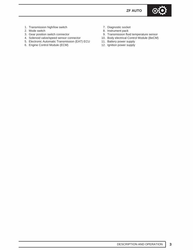
7. Diagnostic socket8. Instrument pack9. Transmission fluid temperature sensor
10. Body electrical Control Module (BeCM)11. Battery power supply12. Ignition power supply
44 AUTOMATIC GEARBOX NEW RANGE ROVER
4 DESCRIPTION AND OPERATION
AUTOMATIC TRANSMISSION - DESCRIPTION
General
The ZF4HP22 transmission is used on 2.5 litre Dieseland 4.0 litre petrol models. 4.6 litre petrol models usethe ZF4HP24 transmission unit to accomodate theincreased power output of the larger engine. Bothunits are of similar construction with the ZF4HP24 unitbeing slightly longer. The operation of both units is thesame.
Automatic transmission vehicles are fitted with an’H-gate’ selector mechanism. The selector mechanismcombines the operation of the transmission selectorlever and the transfer box high/low gear rangeselection. Selections on the selector lever assemblyare transmitted by a selector cable to a gear positionswitch.
The gear position switch on the transmission passesgear selection signals to an Electronic AutomaticTransmission (EAT) ECU located below the LH frontseat, which outputs the appropriate control signals toan electro-hydraulic valve block in the transmission. Amode switch enables the driver to change the controlmode of the EAT ECU between manual, economy andsport. The EAT ECU provides signals to the messagecentre in the instrument pack to indicate the controlmode and system status.
The gearbox features a pressure lubrication systemand is cooled by pumping the lubricant through an oilcooler located in front of the engine cooling radiator.
From 99MY onwards, petrol models feature a revisedEAT ECU with Controller Area Network (CAN) digitalcommunications between the EAT ECU and the ECM.
H-gate selector lever assembly
The selector lever assembly consists of a lever and acover attached to a cast base. The base is located ona gasket and secured to the transmission tunnel andhas an ’H’ pattern for the lever to move in. The lever ishinged to the base and a latch in the lever engageswith detents in the base to provide positive location forthe lever positions. The latch is disengaged bypressing a release button on the lever knob as shownin the lever illustration below.
ZF AUTO
5DESCRIPTION AND OPERATION
Except for lever movement between positions D and 3(high range) and 4 and 3 (low range), the button mustbe pressed before the lever can be moved. In somemarkets, vehicles incorporate an interlock solenoid atthe bottom of the lever, which prevents the lever beingmoved from P unless the ignition switch is in positionII and the foot brake is applied.
The cover incorporates LED lever position indicatorsand the mode switch. The lever position indicatorsilluminate to show the position of the selector lever.The driver’s side of the H-gate is labelled ’Hi’ and isused to select the high range gears. The passengerside of the H-gate is labelled ’Lo’ and is used to selectthe low range gears. Movement of the selector leveracross the H-gate selects high and low transfer boxgear ranges.
The LED indicators are controlled by the Bodyelectrical Control Module (BeCM). A mode switch islocated on the driver’s side of the cover. The modeswitch is used by the driver to select sport mode usedin the high range gears and manual mode used in thelow range gears. The mode switch is a non-latchinghinged switch that, when pressed, connects an earthto the EAT ECU to request a change of mode. Sportand Manual indicator lamps on the cover illuminate toshow the mode selected. The message centre in theinstrument pack also displays ’S’ for sport mode and’LM’ for manual mode along with the selected gear.
An electrical connector at the rear of the coverconnects the selector lever assembly to the vehiclewiring.
Selector cable
The selector cable is a Bowden type cable thatconnects the selector lever assembly to a selectorlever on the gearbox. ’C’ clips secure the ends of theouter cable to brackets on the selector lever assemblyand the selector lever. The inner cable is adjustable atthe connection of the inner cable with the gearboxselector lever.
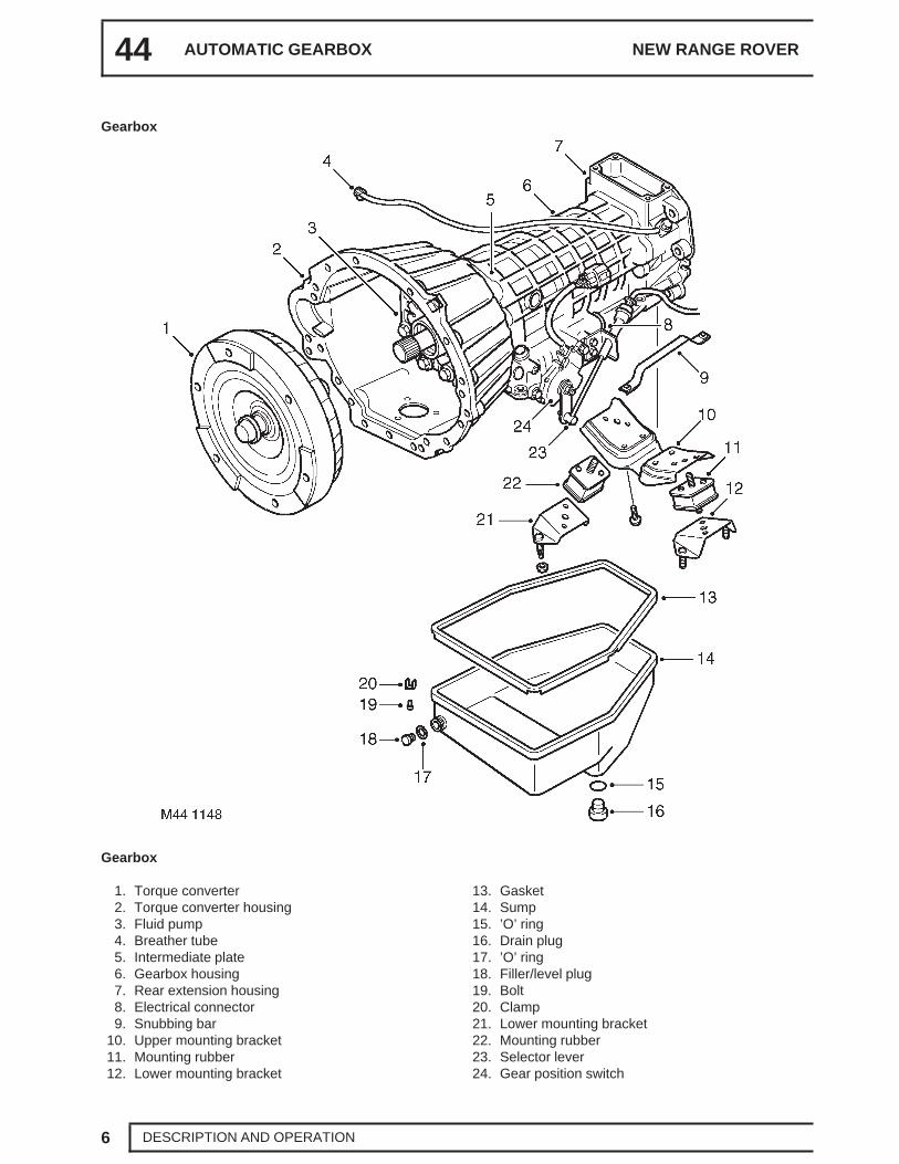
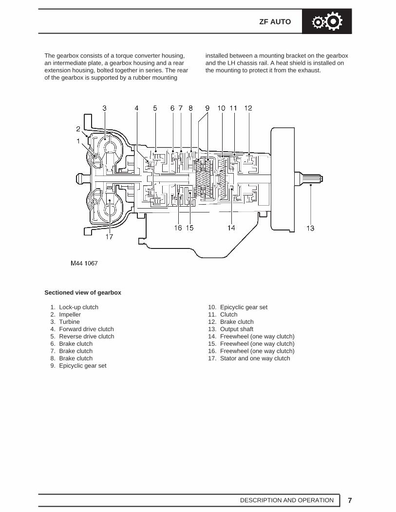
The gearbox consists of a torque converter housing,an intermediate plate, a gearbox housing and a rearextension housing, bolted together in series. The rearof the gearbox is supported by a rubber mounting
installed between a mounting bracket on the gearboxand the LH chassis rail. A heat shield is installed onthe mounting to protect it from the exhaust.
10. Epicyclic gear set11. Clutch12. Brake clutch13. Output shaft14. Freewheel (one way clutch)15. Freewheel (one way clutch)16. Freewheel (one way clutch)17. Stator and one way clutch
On 2.5 litre Diesel models a 260 mm (10.2 in)diameter torque converter is used. On 4.0 and 4.6 litrepetrol models a 280 mm (11 in) diameter torqueconverter is used. On 4.6 litre petrol models up to99MY the torque converter is longer than the torqueconverter used on 4.0 litre petrol models. From 99MY,both the 4.0 and 4.6 litre petrol models use the shortertorque converter previously used on up to 99MY 4.0litre models.
The torque converter housing attaches the gearbox tothe engine and contains the torque converter. Thetorque converter is connected to the engine driveplate and transmits the drive from the engine to thegearbox input shaft. When engaged, a hydrauliclock-up clutch in the torque converter preventsslippage, to give a direct drive from the engine to thegearbox for improved efficiency.
Intermediate plate
The intermediate plate supports the gearbox inputshaft and provides the interface between thetransmission fluid pump and the lubrication circuit.The pump attaches to the front of the intermediateplate and is driven by an impeller in the torqueconverter. The pump pressurises transmission fluiddrawn from the sump on the gearbox housing. Thepressurised fluid then circulates through the torqueconverter and gearbox housing components forcooling, lubrication and gear shift purposes. Portsaround the outer periphery of the intermediate plateprovide the inlet and outlet connections to the fluidcooler and a pressure take-off point for servicing.
On ZF4HP24 gearboxes, the intermediate plate is15 mm (0.6 in) thicker than fitted to the ZF4HP22gearbox to accomodate a larger fluid pump unit. Tocompensate for the increased length of theintermediate plate, the rear extension housing is15 mm (0.6 in) shorter than that fitted to the ZF4HP22gearbox.
Gearbox housing
The gearbox housing contains two epicyclic gear setson input and output shafts. Hydraulic clutches on theshafts control which elements of the gear sets areengaged, and their direction of rotation, to produce theP and N selections, four forward gear ratios and onereverse gear ratio.
Gear ratios
Gear Ratio
1st 2.480:1
2nd 1.480:1
3rd 1.000:1
4th 0.728:1
Reverse 2.086:1
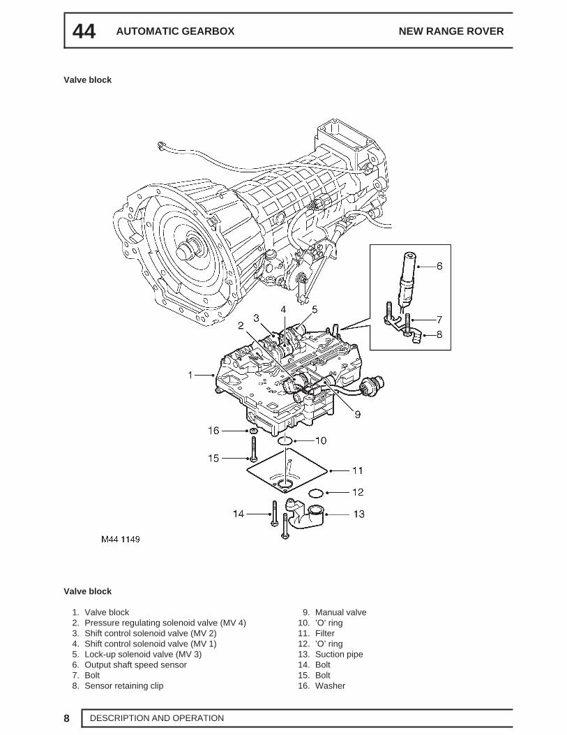
The lock-up and brake clutches are operated bypressurised transmission fluid from the valve block inthe sump. A manual valve and four solenoid valves,also known as Motorised Valves (MV), control thesupply of pressurised transmission fluid from the valveblock:
• The manual valve controls the fluid supply for P,R, N and D selector positions. The four solenoidvalves operate accordingly to operate shiftcontrol, lock-up and shift quality.
• Solenoid valves MV 1 and MV 2 control thesupplies that operate the brake clutches for shiftcontrol. They are also used to prevent accidentalengagement of reverse when moving forwardsand a forward gear when moving backwards.
• Solenoid valve MV 3 controls the supply thatoperates the lock-up clutch.
• Solenoid valve MV 4 modulates the pressure ofthe supplies to the brake clutches, to control shiftquality.
Operation of the manual valve is controlled by theselector lever assembly. In the gearbox, a selectorshaft engages with the manual valve. The selectorshaft is connected to the selector lever assembly viathe selector cable and a selector lever on the left sideof the gearbox. The selector shaft also operates amechanism that locks the output shaft when P isselected.
Operation of the solenoid valves is controlled by theEAT ECU.
44 AUTOMATIC GEARBOX NEW RANGE ROVER
10 DESCRIPTION AND OPERATION
An output shaft speed sensor in the gearbox housingoutputs a signal to the EAT ECU. The EAT ECUcompares output shaft speed with engine speed todetermine the engaged gear and output shaft speedwith vehicle speed to confirm the range selected onthe transfer box. The speed sensor signal is adiagnostic function and not essential for correctgearbox operation.
A bayonet lock electrical connector in the gearboxcasing, to the rear of the selector lever, connects thesolenoid valves and the output shaft speed sensor tothe vehicle wiring.
A pressed steel sump encloses the valve block andcollects transmission fluid draining from the gearboxhousing. A suction pipe and filter on the underside ofthe valve block connect to the inlet side of the fluidpump. A magnet is installed in the sump to collect anymagnetic particles that may be present. A level plugand a drain plug are installed in the sump forservicing.
Rear extension housing
The rear extension housing provides the interfacebetween the gearbox housing and the transfer box. Asplined output shaft transmits the drive from thegearbox to the transfer box. A seal in the rear of thehousing prevents leakage past the extension shaft. Abreather pipe, attached to the left side of the rearextension housing, ventilates the interior of thegearbox and rear extension housings to atmosphere.The open end of the breather pipe is located in theengine compartment at the right rear corner of theengine, against the bulkhead. On 99MY V8 vehicles,the breather pipe is also located against the bulkhead,but the open end is routed down the bulkhead andlocated below the converter housing.
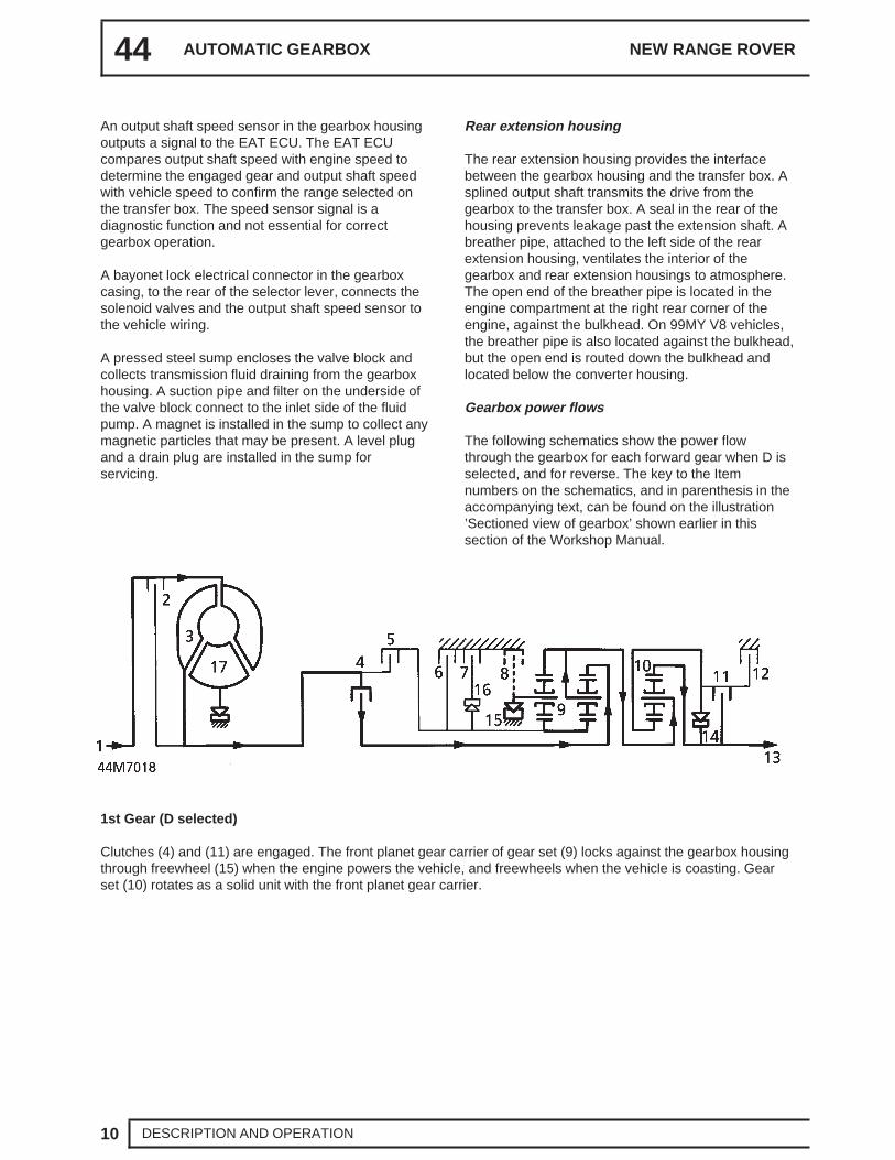
Gearbox power flows
The following schematics show the power flowthrough the gearbox for each forward gear when D isselected, and for reverse. The key to the Itemnumbers on the schematics, and in parenthesis in theaccompanying text, can be found on the illustration’Sectioned view of gearbox’ shown earlier in thissection of the Workshop Manual.
1st Gear (D selected)
Clutches (4) and (11) are engaged. The front planet gear carrier of gear set (9) locks against the gearbox housingthrough freewheel (15) when the engine powers the vehicle, and freewheels when the vehicle is coasting. Gearset (10) rotates as a solid unit with the front planet gear carrier.
ZF AUTO
11DESCRIPTION AND OPERATION
2nd Gear (D selected)
Clutches (4), (6), (7) and (11) are engaged. Freewheel (15) overruns. The hollow shaft with the sun wheel of gearset (9) is locked. Gear set (10) also rotates as a solid unit.
3rd Gear (D selected)
Clutches (4), (5), (7) and (11) are engaged. Freewheels (15) and (16) are overrun. Gear sets (9) and (10) rotate asa solid unit.
4th Gear (D selected)
Clutches (4), (5), (7) and (12) are engaged. Freewheels (14), (15) and (16) are overrun. Gear set (9) rotates as asolid unit. The hollow shaft with the sun wheel of gear set (10) is locked.
44 AUTOMATIC GEARBOX NEW RANGE ROVER
12 DESCRIPTION AND OPERATION
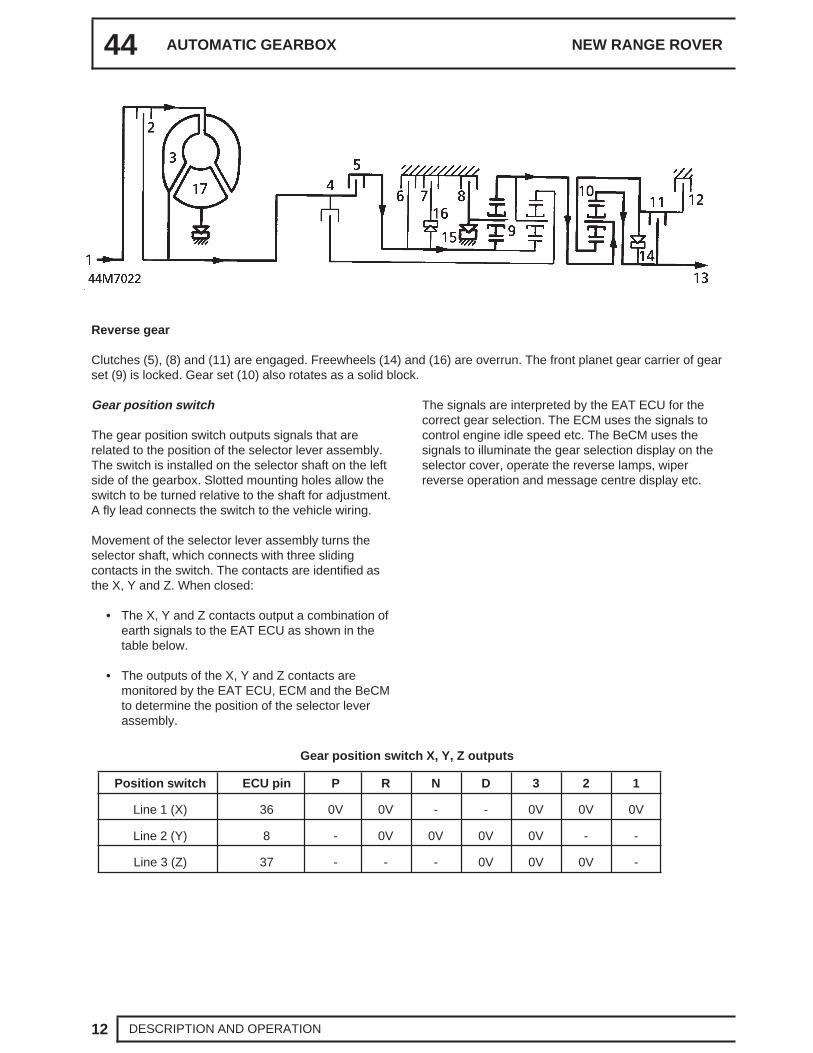
Reverse gear
Clutches (5), (8) and (11) are engaged. Freewheels (14) and (16) are overrun. The front planet gear carrier of gearset (9) is locked. Gear set (10) also rotates as a solid block.
Gear position switch
The gear position switch outputs signals that arerelated to the position of the selector lever assembly.The switch is installed on the selector shaft on the leftside of the gearbox. Slotted mounting holes allow theswitch to be turned relative to the shaft for adjustment.A fly lead connects the switch to the vehicle wiring.
Movement of the selector lever assembly turns theselector shaft, which connects with three slidingcontacts in the switch. The contacts are identified asthe X, Y and Z. When closed:
• The X, Y and Z contacts output a combination ofearth signals to the EAT ECU as shown in thetable below.
• The outputs of the X, Y and Z contacts aremonitored by the EAT ECU, ECM and the BeCMto determine the position of the selector leverassembly.
The signals are interpreted by the EAT ECU for thecorrect gear selection. The ECM uses the signals tocontrol engine idle speed etc. The BeCM uses thesignals to illuminate the gear selection display on theselector cover, operate the reverse lamps, wiperreverse operation and message centre display etc.
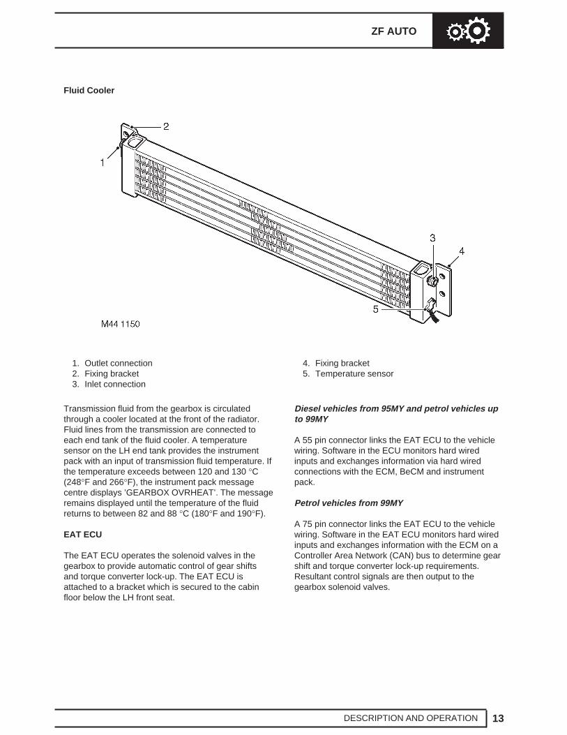
Transmission fluid from the gearbox is circulatedthrough a cooler located at the front of the radiator.Fluid lines from the transmission are connected toeach end tank of the fluid cooler. A temperaturesensor on the LH end tank provides the instrumentpack with an input of transmission fluid temperature. Ifthe temperature exceeds between 120 and 130 °C(248°F and 266°F), the instrument pack messagecentre displays ’GEARBOX OVRHEAT’. The messageremains displayed until the temperature of the fluidreturns to between 82 and 88 °C (180°F and 190°F).
EAT ECU
The EAT ECU operates the solenoid valves in thegearbox to provide automatic control of gear shiftsand torque converter lock-up. The EAT ECU isattached to a bracket which is secured to the cabinfloor below the LH front seat.
Diesel vehicles from 95MY and petrol vehicles upto 99MY
A 55 pin connector links the EAT ECU to the vehiclewiring. Software in the ECU monitors hard wiredinputs and exchanges information via hard wiredconnections with the ECM, BeCM and instrumentpack.
Petrol vehicles from 99MY
A 75 pin connector links the EAT ECU to the vehiclewiring. Software in the EAT ECU monitors hard wiredinputs and exchanges information with the ECM on aController Area Network (CAN) bus to determine gearshift and torque converter lock-up requirements.Resultant control signals are then output to thegearbox solenoid valves.
44 AUTOMATIC GEARBOX NEW RANGE ROVER
14 DESCRIPTION AND OPERATION
The CAN bus, introduced on 99MY petrol vehicles,provides the communication link between the ECMand the EAT ECU. Inputs and outputs to and fromeach control unit are transmitted via two twisted wireconnections, CAN high and CAN low.
The CAN bus allows more engine data to be passedto the EAT ECU which, on earlier vehicles, wouldrequire a number of additional hardwired connections.
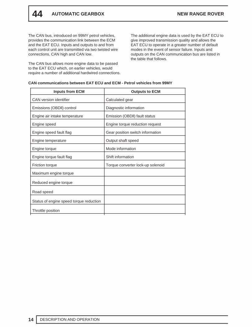
The additional engine data is used by the EAT ECU togive improved transmission quality and allows theEAT ECU to operate in a greater number of defaultmodes in the event of sensor failure. Inputs andoutputs on the CAN communication bus are listed inthe table that follows.
CAN communications between EAT ECU and ECM - Petrol vehicles from 99MY
Inputs from ECM Outputs to ECM
CAN version identifier Calculated gear
Emissions (OBDll) control Diagnostic information
Engine air intake temperature Emission (OBDll) fault status
Engine speed Engine torque reduction request
Engine speed fault flag Gear position switch information
Engine temperature Output shaft speed
Engine torque Mode information
Engine torque fault flag Shift information
Friction torque Torque converter lock-up solenoid
Maximum engine torque
Reduced engine torque
Road speed
Status of engine speed torque reduction
Throttle position
ZF AUTO
15DESCRIPTION AND OPERATION
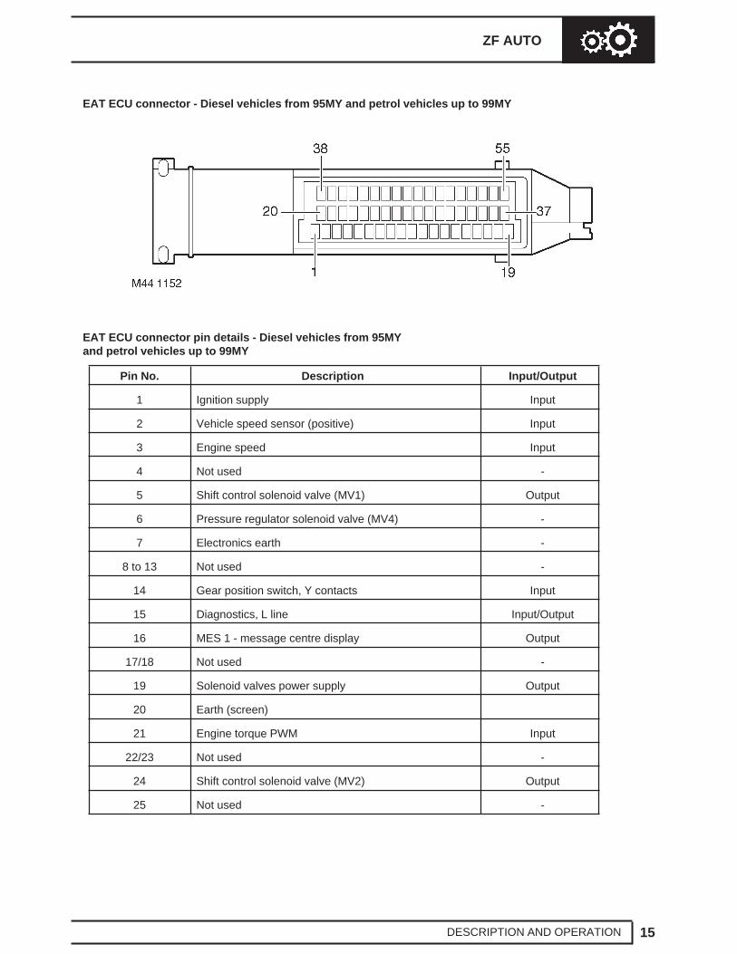
EAT ECU connector - Diesel vehicles from 95MY and petrol vehicles up to 99MY
EAT ECU connector pin details - Diesel vehicles from 95MYand petrol vehicles up to 99MY
Pin No. Description Input/Output
1 Ignition supply Input
2 Vehicle speed sensor (positive) Input
3 Engine speed Input
4 Not used -
5 Shift control solenoid valve (MV1) Output
6 Pressure regulator solenoid valve (MV4) -
7 Electronics earth -
8 to 13 Not used -
14 Gear position switch, Y contacts Input
15 Diagnostics, L line Input/Output
16 MES 1 - message centre display Output
17/18 Not used -
19 Solenoid valves power supply Output
20 Earth (screen)
21 Engine torque PWM Input
22/23 Not used -
24 Shift control solenoid valve (MV2) Output
25 Not used -
44 AUTOMATIC GEARBOX NEW RANGE ROVER
16 DESCRIPTION AND OPERATION
EAT ECU connector pin details - Diesel vehicles from 95MYand petrol vehicles up to 99MY (continued)
Pin No. Description Input/Output
26 Power earth -
27/28 Not used -
29 Mode switch Input
31 MES 2 - message centre display Output
30 Not used -
32 Torque reduction request Output
33 Gear position switch, Z contacts Input
34 to 37 Not used -
38 Vehicle speed sensor (negative) Input
39 Battery supply Input
40/41 Not used -
42 Torque converter solenoid (MV3) Output
43 to 45 Not used -
46 Transmission high/low switch Input
47 Throttle position PWM Input
48/49 Not used -
50 Gear position switch, X contacts Input
51 Diagnostics, K line Input/Output
51 to 55 Not used -
ZF AUTO
17DESCRIPTION AND OPERATION
EAT ECU connector - Petrol vehicles from 99MY
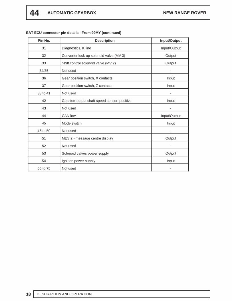
EAT ECU connector pin details - Petrol vehicles from 99MY
The gear position switch outputs are monitored by theBeCM and the EAT ECU. The BeCM outputs gearposition signals to illuminate the position indicatorseach side of the gear selector lever and on themessage centre in the instrument pack.
In D, 3, 2, and 1, the EAT ECU outputs control signalsto the gearbox to select the required gear.
In D, all forward gears are available for selection bythe EAT ECU. In 3, 2 and 1, a corresponding limit isimposed on the highest gear available for selection.When R is selected, reverse gear only engages if thevehicle is stationary or moving at 5 mph (8 km/h) orless.
Selector Lever Interlock (where fitted)
The interlock solenoid on the selector lever isde-energised unless the foot brake is applied whilethe ignition is on. While de-energised, the interlocksolenoid allows the selector lever to move through therange unless P is selected.
On entering the P position, the interlock solenoidengages a latch which locks the selector lever. Whenthe ignition is on and the foot brake is applied, theBeCM energises the interlock solenoid, whichdisengages the latch and allows the selector lever tobe moved out of P.
Economy, Sport and Manual Modes
During the power-up procedure after the ignition isswitched on, the EAT ECU defaults to an economymode. Pressing the mode switch causes the EATECU to change between the economy mode and thesport or the manual mode, depending on the rangeselected on the transfer box:
• If the transfer box is in high range, the EAT ECUchanges to the sport mode and illuminates thesport mode lamp on the selector cover anddisplays ’S’ in the instrument pack messagecentre. In the sport mode the gearbox is moreresponsive to accelerator pedal movement.Downshifts occur earlier and upshifts occur later.
• If the transfer box is in low range, the EAT ECUchanges to the manual mode and illuminates themanual mode lamp on the selector cover anddisplays ’LM’ in the instrument pack messagecentre. Kickdown is disabled and the EAT ECUmaintains the gearbox in the gear selected onthe selector lever (D = 4th gear) to giveimproved off road performance. Downshiftsoccur only to prevent the engine stalling.
From a standing start, the vehicle pulls away in1st gear and, if a higher gear is selected,upshifts almost immediately to the selected gear(shifts of more than one gear can occur).
• After a second press of the mode switch the EATECU reverts to the economy mode, for the rangeselected on the transfer box, and extinguishesthe related mode lamp on the selector cover andremoves the ’S’ or ’LM’ display in the instrumentpack message centre.
• When the vehicle is in the default mode (i.e. highrange and economy) and towing or driving upsteep gradients, the EAT ECU will select a shiftpattern appropriate to the driving conditions. If aheavy trailer is being towed or a steep gradientis encountered, the transmission will hold in thegears longer than in normal operation.
Shift Control
To provide the different driving characteristics for eachmode of operation, the EAT ECU incorporatesdifferent shift maps of throttle position/road speed.Base shift points are derived from the appropriate shiftmap. When a shift is required, the EAT ECU sends arequest to the ECM for a reduction in engine torque, inorder to produce a smoother shift. The percentage oftorque reduction requested varies according to theoperating conditions at the time of the request.
44 AUTOMATIC GEARBOX NEW RANGE ROVER
20 DESCRIPTION AND OPERATION
When the EAT ECU receives confirmation of thetorque reduction from the ECM, it then signals theshift solenoid valves in the gearbox to produce theshift. To further improve shift quality, the EAT ECUalso signals the pressure regulating solenoid valve tomodulate the hydraulic pressure and so control therate of engagement and disengagement of the brakeclutches.
With time, the components in a gearbox wear and theduration of the gear shifts tends to increase, whichhas an adverse affect on the brake clutches. Tocounteract this, the EAT ECU applies a pressureadaptation to each shift. To calculate the adaptations,the EAT ECU monitors the pressure modulation used,and time taken, for each shift. If a subsequent shift ofthe same type, in terms of throttle position and enginespeed, has a longer duration, the EAT ECU stores anadaptation for that type of shift in a volatile memory.The adaptation is then included in future pressurecalculations for that type of shift, to restore shiftduration to the nominal.
Kickdown
The EAT ECU monitors the input of the throttleposition sensor to determine when kickdown isrequired and select a gear to give the best availableacceleration. When it detects a kickdown situation, theEAT ECU immediately initiates a down shift of one ortwo gears or will maintain the current gear to avoidengine overspeed.
Torque Converter Lock-Up
The EAT ECU energises the lock-up solenoid valve toengage the lock-up clutch. Lock-up clutch operation isdependent on throttle position, engine speed,operating mode and the range selected on thetransfer box.
High Range
Unique lock-up maps, similar to the shift maps, areincorporated in the economy and sport modes for allforward gears. Engagement and disengagement ofthe lock-up clutch is dependent on throttle positionand engine speed.
Low Range
To enhance off road control, particularly whenmanoeuvring at low speeds, torque converter lock-updoes not occur when there is any degree of throttleopening. When the throttle is closed above a presetengine speed, the lock-up clutch engages to providemaximum engine braking.
Increased Load/Reduced Torque Compensation
To aid performance and driveability in the high rangeeconomy mode, the EAT ECU has three adaptive shiftand lock-up maps. These maps delay upshifts andtorque converter lock-up similar to the sport mode ifthe inputs from the engine indicate:
• A sustained high load on the engine, such asoccurs when the vehicle is ascending a steepgradient or towing a trailer.
• The EAT ECU monitors the engine inputs andselects the most appropriate adaptive map forthe prevailing conditions.
• On vehicles from 99MY, a lower than normalengine torque, such as occurs at altitude or highambient temperatures.
Diagnostics
While the ignition is on, the EAT ECU diagnoses thesystem for faults. The extent of the diagnosticcapability at any particular time depends on theprevailing operating conditions, e.g. it is not possibleto check torque converter lock-up while the vehicle isstationary, or to check for a short circuit to earth if thecircuit concerned is already at a low potential.
If a fault is detected, the EAT ECU immediately storesa fault code and the values of three operatingparameters associated with the fault. Depending onthe fault, there are four possible effects:
• The fault has little effect on gearbox operation orvehicle emissions. The driver will probably notnotice any change and the warning lampsremain extinguished.
• All gears are available but kickdown does notfunction. ’GEARBOX FAULT’ will be displayedon the instrument pack message centre. TheMIL remains extinguished.
• Limp home mode is selected and vehicleperformance is greatly reduced. ’GEARBOXFAULT’ will be displayed on the instrument packmessage centre. If the fault is detected on asecond consecutive drive cycle, the MILilluminates.
ZF AUTO
21DESCRIPTION AND OPERATION
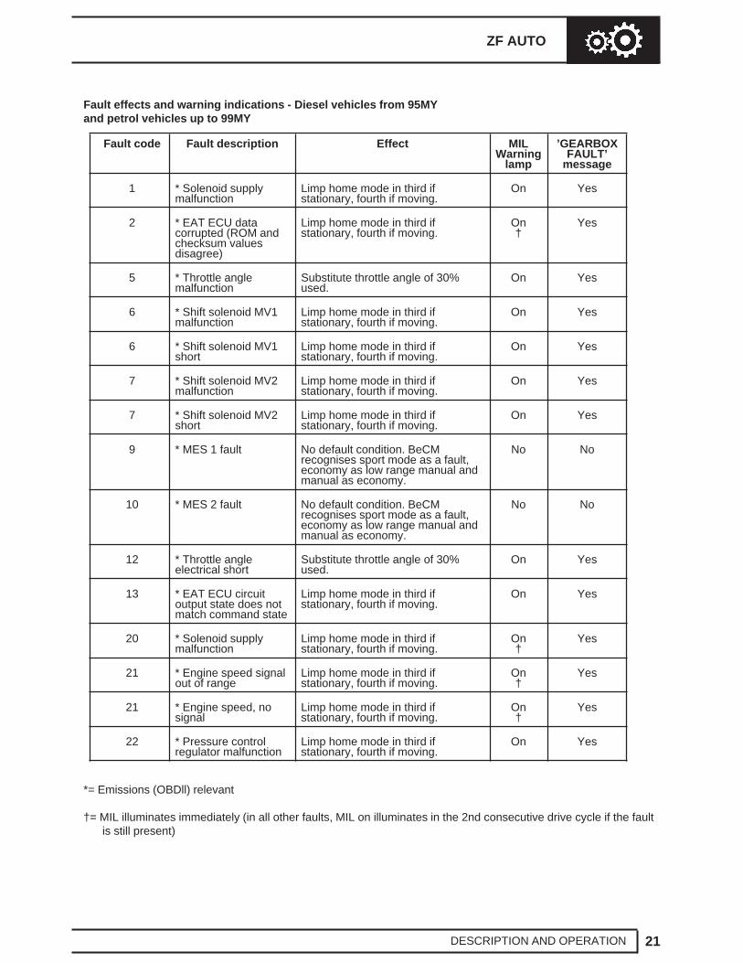
Fault effects and warning indications - Diesel vehicles from 95MYand petrol vehicles up to 99MY
Fault code Fault description Effect MILWarning
lamp
’GEARBOXFAULT’
message
1 * Solenoid supplymalfunction
Limp home mode in third ifstationary, fourth if moving.
Limp home mode in low and highranges. Shift pressure to maximum,harsh gear shifts/engagement.
On Yes
P1613(1)
* Solenoid valvespower supply relay,sticking open or shortcircuit
Limp home mode in low and highranges. Shift pressure to maximum,harsh gear shifts/engagement.
On Yes
P1705(39)
Transmission high/lowrange, implausibleinput
No apparent effect. On No
P1810(12, 13)
BeCM to messagecentre circuit fault
Message centre does not display ’S’or ’LM’. No effect on gearboxoperation.
On No
P1841(16)
* CAN bus fault Maintains current gear in low range,limp home mode in high range. Shiftpressure to maximum, harsh gearshifts/engagement.
On Yes
P1842(15)
* CAN levelmonitoring
Maintains current gear in low range,limp home mode in high range. Shiftpressure to maximum, harsh gearshifts/engagement.
On Yes
*= Emissions (OBDll) relevant
†= MIL illuminates immediately (in all other faults, MIL on illuminates in the 2nd consecutive drive cycle if the faultis still present)
ZF AUTO
25DESCRIPTION AND OPERATION
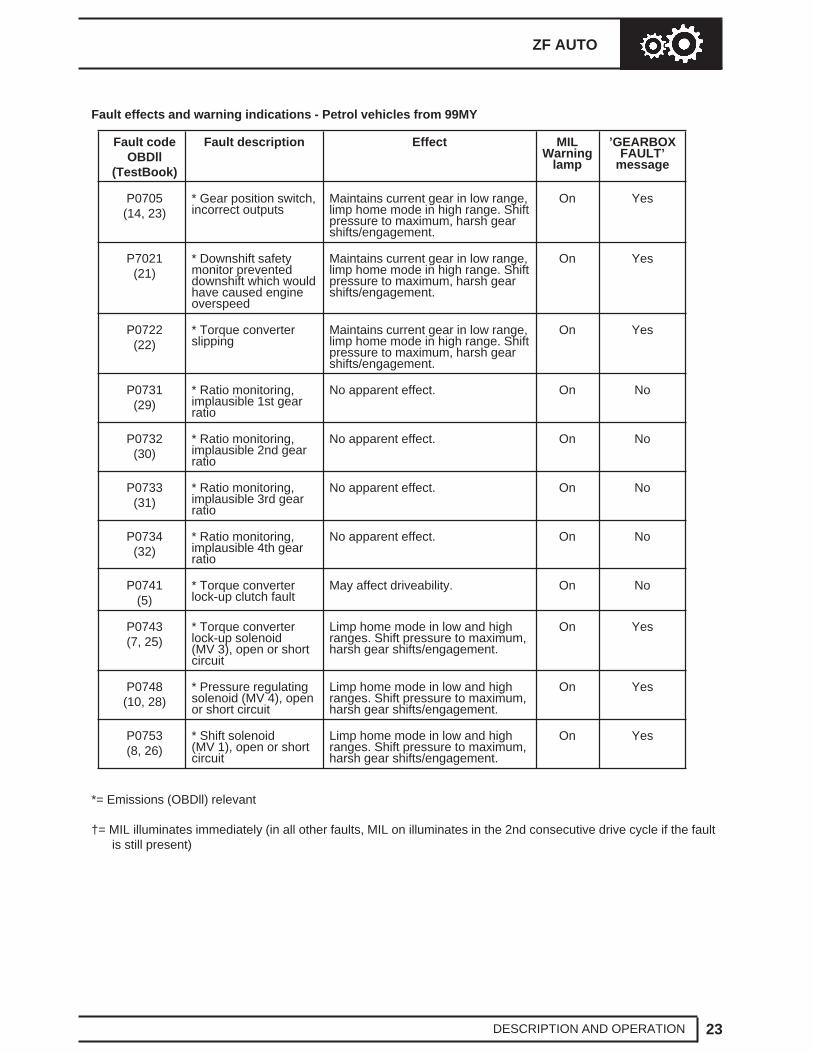
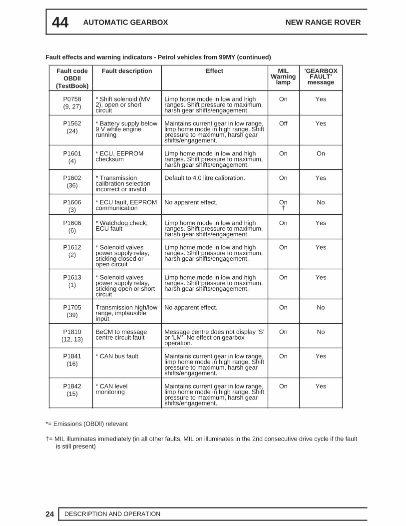
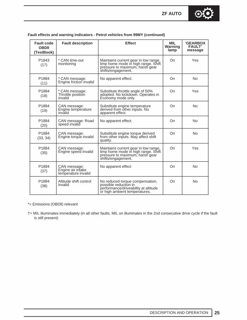
Fault effects and warning indicators - Petrol vehicles from 99MY (continued)
Fault codeOBDll
(TestBook)
Fault description Effect MILWarning
lamp
’GEARBOXFAULT’
message
P1843(17)
* CAN time-outmonitoring
Maintains current gear in low range,limp home mode in high range. Shiftpressure to maximum, harsh gearshifts/engagement.
On Yes
P1884(11)
* CAN message:Engine friction invalid
No apparent effect. On No
P1884(18)
* CAN message:Throttle positioninvalid
Substitute throttle angle of 50%adopted. No kickdown. Operates inEconomy mode only.
On Yes
P1884(19)
CAN message:Engine temperatureinvalid
Substitute engine temperaturederived from other inputs. Noapparent effect.
On No
P1884(20)
CAN message: Roadspeed invalid
No apparent effect. On No
P1884(33, 34)
CAN message:Engine torque invalid
Substitute engine torque derivedfrom other inputs. May affect shiftquality.
On No
P1884(35)
CAN message:Engine speed invalid
Maintains current gear in low range,limp home mode in high range. Shiftpressure to maximum, harsh gearshifts/engagement.
On Yes
P1884(37)
CAN message:Engine air intaketemperature invalid
No apparent effect On No
P1884(38)
Altitude shift controlinvalid
No reduced torque compensation,possible reduction inperformance/driveability at altitudeor high ambient temperatures.
On No
*= Emissions (OBDll) relevant
†= MIL illuminates immediately (in all other faults, MIL on illuminates in the 2nd consecutive drive cycle if the faultis still present)
44 AUTOMATIC GEARBOX NEW RANGE ROVER
26 DESCRIPTION AND OPERATION
The fault codes can be accessed using TestBook. Onvehicles up to 99MY the automatic transmission faultcodes are a numeric code recognised by TestBook.On V8 vehicles from 99MY the automatic transmissionfault codes are both numeric and OBDII ’P’ codesrecognised by TestBook and other suitable scantools.
After the detection of a fault, the effects remain activefor the remainder of the drive cycle. In subsequentdrive cycles, as soon as the EAT ECU diagnoses thefault is no longer present, it resumes normal control ofthe gearbox. The conditions required to diagnose thatthe fault is no longer present depend on the fault.Some faults require the engine to be started, othersrequire only that the ignition is switched on.
After a fault has not recurred for forty warm-up cycles,the fault is deleted from the EAT ECU memory. Onlyfive different faults can be stored in the memory at anyone time. If a further fault occurs, the fault with thelowest priority will be replaced by the new fault.
Mechanical Limp Home
In the mechanical limp home mode in high range,gear engagement is controlled by the manual valve.The gearbox is fixed in 4th gear if the fault occurswhile the vehicle is moving, or 3rd gear if the faultoccurs while the vehicle is stationary. 3rd gear is alsoengaged if a vehicle is brought to a stop and theselector lever is moved out of, and back into, D.
Neutral and reverse gear are also available.
In the mechanical limp home mode in low range,depending on the severity of the fault, the engagedgear is held until the vehicle is brought to a stop. Thegearbox then selects and holds 3rd gear.
Calibration Selection
EAT ECU’s differ between NAS, UK/Europe and ROWmarkets and are identified by differentiation betweenthe part numbers.
On V8 vehicles from 99MY, the ECU contains twocalibrations for 4.0 and 4.6 litre engines. When areplacement ECU is fitted, the correct ECU calibrationmust be selected or the ECU will store a gearbox faultand ’GEARBOX FAULT’ will be displayed in themessage centre. The vehicle can still be driven and isnot in ’limp home mode’.
Removed EAT ECU’s remember their calibrationsetting and if re-fitted to the same vehicle will notrequire calibration. A new EAT ECU will requirecalibration using TestBook.
If an ECU is fitted from another vehicle, the messagecentre will not display the ’GEARBOX FAULT’message. The correct calibration level must beselected or premature gearbox failure will occur.
ZF AUTO
27DESCRIPTION AND OPERATION
USING THE H-GATE
To make a change from high to low or vice versa, thevehicle must be stationary.
• Apply the brakes and select ’N’
• Move the selector lever into the cross-piece ofthe ’H-gate’ and select the new gear range, thepanel illumination will flash before becomingconstant and an audible warning will sound.
• When the illumination is constant select the gearrequired.
CAUTION: If a gear is selected before thegear transfer is complete, a ’clunk’ orgrinding sound will be heard because the
electric shift motor has not completed theoperation.If this occurs and the panel illumination continuesto flash, reselect neutral and try again when theillumination becomes constant.If the vehicle is moving when a transfer gearchange is attempted, the message centre willdisplay ’SLOW DOWN’.If an attempt is made to change the gear rangewith the gear selector out of neutral, ’SELECTNEUTRAL’ will be displayed.
High Range Gears
Use the high range for all normal road driving andoff-road driving across dry, level terrain. An audiblewarning will sound, the selector lever illumination willflash and the transfer box warning lamp will flashwhile the range change is taking place. The messagecentre will momentarily display ’HIGH’ as soon as highrange is selected, and then display the gear selected.
Selector lever positions:
’P’ Park
In this position the wheels are locked to prevent thevehicle from moving. Select only with the vehiclestationary.
’R’ Reverse
Select only when the vehicle is stationary.
’N’ Neutral
Use this position when the vehicle is stationary andthe engine is to idle for a short period.
’D’ Drive
Select ’D’ for all normal driving on good road surfaces.Fully automatic gear changing occurs on all forwardgears according to vehicle speed and acceleratorposition.
’3’
Automatic gear changing is limited to first, second andthird gears only. Use in congested traffic conditionsand for town driving.
’2’
Automatic gear changing is limited to first and secondgear ratios only. Use when driving up steep gradientsand for negotiating very narrow, twisting roads. Thisposition also provides moderate engine braking fordescending slopes.
’1’
First gear should only be used on very severegradients, especially when towing or when maximumengine braking is required.
NOTE: If position ’2’ or ’1’ is selected from’D’ or ’3’ while the vehicle is travelling athigh speed, then third gear will
immediately engage. Progressive deceleration willthen cause downshifts into second and then firstgear when appropriately low road speeds arereached.
44 AUTOMATIC GEARBOX NEW RANGE ROVER
28 DESCRIPTION AND OPERATION
’Sport’ Mode
In ’Sport’ mode gear changing is delayed to makeoptimum use of the engine’s power when increasedacceleration is required or when negotiating longinclines or twisting roads. Press the mode switch, withthe gearbox in high range, to select ’Sport’ mode. Themessage centre will momentarily display ’SPORT’ andthen ’S’ along with the selected gear. Pressing theswitch a second time returns the gearbox to its normaloperation within the high range.
Low Range Gears
Use low range gears in any situation where low speedmanoeuvring is necessary, such as reversing a traileror negotiating a boulder strewn river bed; also use lowrange for extreme off-road conditions. An audiblewarning will sound, the selector lever illumination willflash and the transfer box warning lamp will flashwhile the range change is taking place. The messagecentre will momentarily display ’LOW’ when the lowrange is selected, and then ’L’ along with the relevantgear selected.
Selector lever positions:
’P’ Park
As high range.
’R’ Reverse
As high range
’N’ Neutral
As high range
’4’
Select ’4’ to optimize vehicle performance for goodoff-road conditions; fully automatic gear changingoccurs on all forward gears according to vehiclespeed and accelerator position.
’3’
Automatic gear changing is limited to first, second andthird gears only and should be used for reasonableoff-road conditions and ascending gradients.
’2’
Automatic gear changing is limited to first and secondratios only when maximum engine performance isrequired to ascend steep gradients. This position alsoprovides moderate engine braking for descendingslopes.
’1’
Select ’1’ on very severe gradients, particularly whentowing, when maximum engine performance andengine braking is required.
ZF AUTO
29DESCRIPTION AND OPERATION
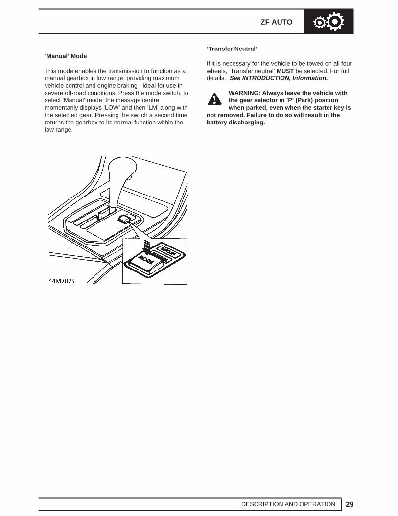
’Manual’ Mode
This mode enables the transmission to function as amanual gearbox in low range, providing maximumvehicle control and engine braking - ideal for use insevere off-road conditions. Press the mode switch, toselect ’Manual’ mode; the message centremomentarily displays ’LOW’ and then ’LM’ along withthe selected gear. Pressing the switch a second timereturns the gearbox to its normal function within thelow range.
’Transfer Neutral’
If it is necessary for the vehicle to be towed on all fourwheels, ’Transfer neutral’ MUST be selected. For fulldetails. See INTRODUCTION, Information.
WARNING: Always leave the vehicle withthe gear selector in ’P’ (Park) positionwhen parked, even when the starter key is
not removed. Failure to do so will result in thebattery discharging.
3. Select ’P’. Position lever on transmission fullyforward.
4. Adjust trunnion until a sliding fit in transmissionlever is achieved.
5. Connect trunnion to lever. Fit split pin. Tightenlocknut.
6. Remove safety stands. Lower vehicle.
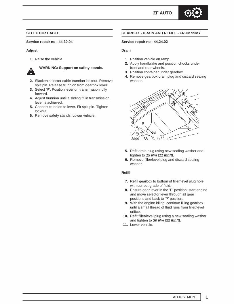
GEARBOX - DRAIN AND REFILL - FROM 99MY
Service repair no - 44.24.02
Drain
1. Position vehicle on ramp.2. Apply handbrake and position chocks under
front and rear wheels.3. Position container under gearbox.4. Remove gearbox drain plug and discard sealing
washer.
5. Refit drain plug using new sealing washer andtighten to 15 Nm (11 lbf.ft).
6. Remove filler/level plug and discard sealingwasher.
Refill
7. Refill gearbox to bottom of filler/level plug holewith correct grade of fluid.
8. Ensure gear lever in the ’P’ position, start engineand move selector lever through all gearpositions and back to ’P’ position.
9. With the engine idling, continue filling gearboxuntil a small thread of fluid runs from filler/levelorifice.
10. Refit filler/level plug using a new sealing washerand tighten to 30 Nm (22 lbf.ft).
11. Lower vehicle.
ZF AUTO
1REPAIR
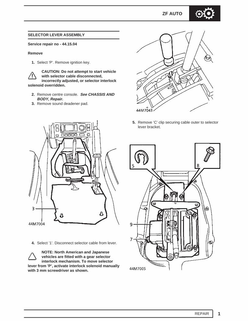
SELECTOR LEVER ASSEMBLY
Service repair no - 44.15.04
Remove
1. Select ’P’. Remove ignition key.
CAUTION: Do not attempt to start vehiclewith selector cable disconnected,incorrectly adjusted, or selector interlock
solenoid overridden.
2. Remove centre console. See CHASSIS ANDBODY, Repair.
3. Remove sound deadener pad.
4. Select ’1’. Disconnect selector cable from lever.
NOTE: North American and Japanesevehicles are fitted with a gear selectorinterlock mechanism. To move selector
lever from ’P’, activate interlock solenoid manuallywith 3 mm screwdriver as shown.
5. Remove ’C’ clip securing cable outer to selectorlever bracket.
44 AUTOMATIC GEARBOX NEW RANGE ROVER
2 REPAIR
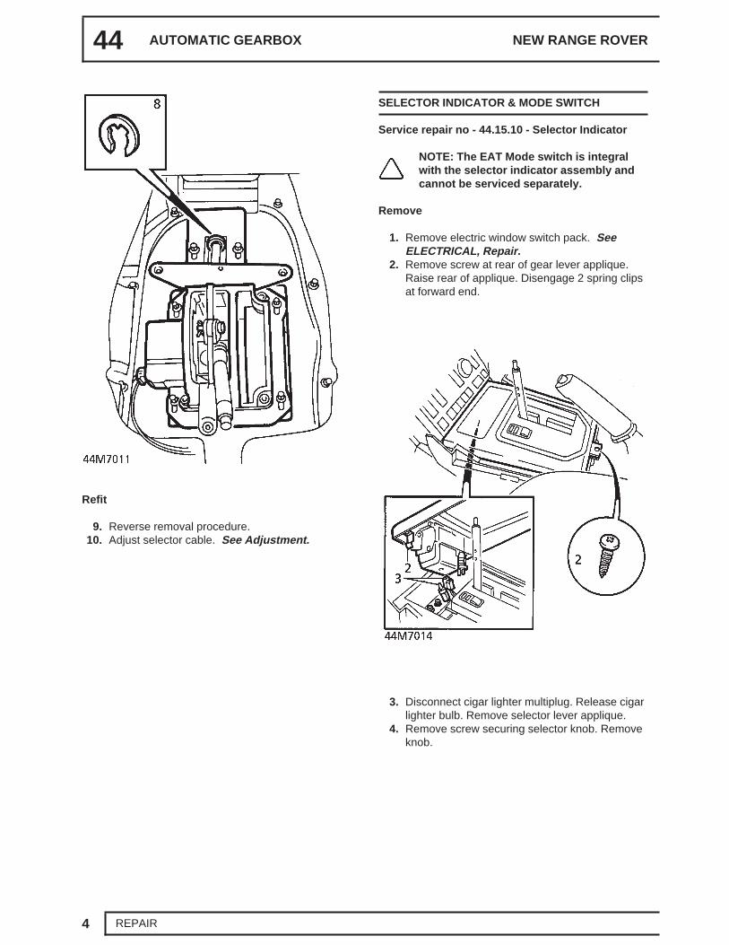
6. If selector lever assembly is to be refitted, markrelationship of lever bracket to transmissiontunnel.
7. Disconnect multiplug.8. Remove 6 bolts securing selector lever
assembly to transmission tunnel.9. Remove selector lever assembly. Collect gasket.
Refit
10. Ensure mating faces are clean.11. Using a new gasket, position selector lever
assembly. Engage cable.12. Fit bolts, finger tight. Align selector lever
assembly with marks.13. New lever only. Temporarily fit selector knob.
Secure with screw. Select ’P’. Adjust position oflever assembly to give dimension ’A’ as shown.Dimension A= 100 mm (3.9 in)Remove selector knob.
14. Tighten selector lever assembly fixings.15. Connect multiplug.16. Secure cable lever bracket with ’C’ clip.17. Align cable to lever. Secure with clevis and split
pins.18. Fit sound deadener pad.19. Fit centre console. See CHASSIS AND BODY,
Repair.20. Engage cable in gearbox abutment bracket.
Secure with ’C’ clip.21. Adjust selector cable. See this section.
ZF AUTO
3REPAIR
SELECTOR CABLE
Service repair no - 44.15.08
Remove
1. Select ’P’. Remove ignition key.
CAUTION: Do not attempt to start vehiclewith selector cable disconnected,incorrectly adjusted, or selector interlock
solenoid overridden.
2. Raise the vehicle.
WARNING: Support on safety stands.
3. Remove split pin and washer securing cabletrunnion to transmission lever.
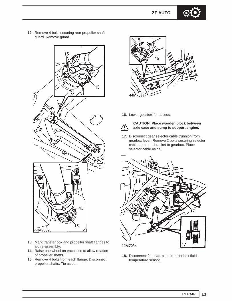
13. Raise one wheel on each axle to allow rotationof propeller shafts.
14. Mark transfer box and propeller shaft flanges toaid re-assembly.
44 AUTOMATIC GEARBOX NEW RANGE ROVER
8 REPAIR
15. Remove 4 bolts from each propeller shaft flange.16. Release propeller shafts and tie aside.17. Lower gearbox for access.
18. Remove split pin securing gear selector cabletrunnion to gear selector lever and releasetrunnion.
19. Remove 2 bolts securing gear selector cableabutment bracket and harness support bracketto gearbox.
20. Position selector cable and bracket aside.21. Lower gearbox support to gain access to
selector shaft.22. Remove valve block. See this section.
23. Disconnect harness from gear selector switchmultiplug and release multiplug from bracket.
24. Remove nut securing selector shaft lever andrelease lever from shaft.
25. Remove bolt and nut securing gear selectorswitch to gearbox and remove switch.
26. Drift out and discard selector quadrant roll pin.Remove selector shaft.
27. Remove selector quadrant and connecting rod.28. Remove oil seal taking care not to damage seal
housing.
ZF AUTO
9REPAIR
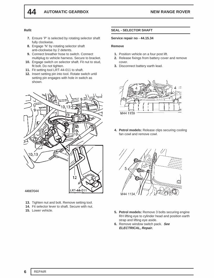
Refit
29. Clean shaft and seal housing.30. Using a suitable adapter, fit new seal.31. Fit selector quadrant and connecting rod.32. Fit selector shaft and secure to quadrant using
new roll pin.33. Fit valve block. See this section.34. Position selector switch and tighten nut and bolt.35. Position selector shaft lever and tighten nut.36. Fit selector switch multiplug to bracket and
connect harness to multiplug.37. Align harness support bracket and gear selector
cable abutment bracket to gearbox and securewith bolts.
38. Connect gear selector cable trunnion to leverand fit split pin.
39. Adjust gear selector cable. See this section.40. Raise gearbox on transmission jack.41. Fit handbrake cable through transmission tunnel.42. Clean propeller shaft and transfer box flanges.43. Fit shafts to transfer box flanges, align marks
and tighten nuts and bolts to 48 Nm (35 lbf.ft).44. Fit rear propeller shaft guard and secure with
bolts.45. Fit transmission mounting assembly and tighten
bolts to 45 Nm (33 lbf.ft).46. Diesel models: Fit chassis crossmember. See
CHASSIS AND BODY, Repair.47. Petrol models: Fit exhaust front pipe. See
MANIFOLD AND EXHAUST SYSTEM, Repair.48. Connect handbrake cable to lever and fit clevis
pin and clip.49. Fit window switch pack. See ELECTRICAL,
Repair.50. Petrol models: Fit engine RH lifting eye, align
earth strap and secure with bolts.51. Petrol models: Fit cooling fan cowl and secure
with clips.52. Connect battery earth lead.53. Fit and secure battery cover.
Repair.3. Remove 4 trim studs securing air deflectors.
Remove deflectors.4. Position container to collect fluid spillage.5. Unscrew fluid cooler pipe union nuts and discard
’O’ rings.
6. Plug cooler and pipes.7. Remove 4 bolts securing fluid cooler to radiator
mounting bracket.8. Remove fluid cooler.
Refit
9. Fit fluid cooler.10. Fit and tighten 4 bolts securing cooler to
mounting bracket.11. Remove plugs from cooler and pipes.12. Ensure pipe unions are clean.13. Lubricate new ’O’rings with clean fluid and fit to
pipes.14. Connect pipes to cooler. Tighten union nuts to
22 Nm (16 lbf.ft)15. Remove container.16. Fit air deflectors and secure with studs.17. Fit engine oil cooler. See ENGINE, Repair.18. Reconnect battery negative lead.19. Top up gearbox fluid. See SECTION 10,
Maintenance.
44 AUTOMATIC GEARBOX NEW RANGE ROVER
10 REPAIR
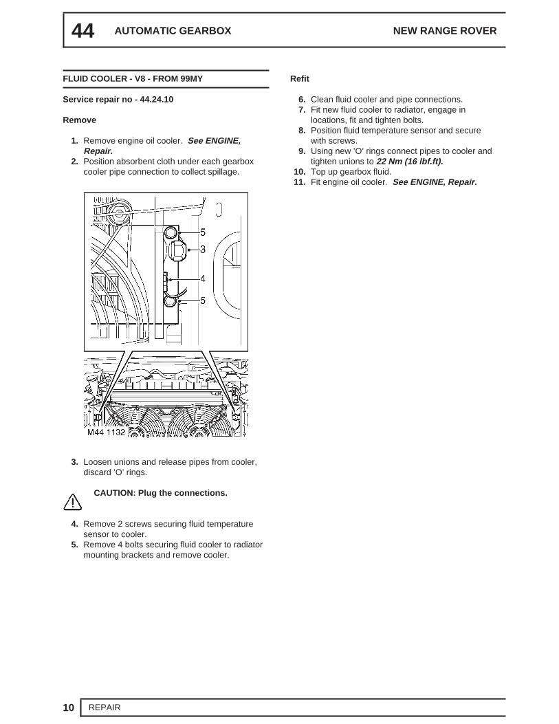
FLUID COOLER - V8 - FROM 99MY
Service repair no - 44.24.10
Remove
1. Remove engine oil cooler. See ENGINE,Repair.
2. Position absorbent cloth under each gearboxcooler pipe connection to collect spillage.
3. Loosen unions and release pipes from cooler,discard ’O’ rings.
CAUTION: Plug the connections.
4. Remove 2 screws securing fluid temperaturesensor to cooler.
5. Remove 4 bolts securing fluid cooler to radiatormounting brackets and remove cooler.
Refit
6. Clean fluid cooler and pipe connections.7. Fit new fluid cooler to radiator, engage in
locations, fit and tighten bolts.8. Position fluid temperature sensor and secure
with screws.9. Using new ’O’ rings connect pipes to cooler and
tighten unions to 22 Nm (16 lbf.ft).10. Top up gearbox fluid.11. Fit engine oil cooler. See ENGINE, Repair.
ZF AUTO
11REPAIR
FLUID COOLER - DIESEL
Service repair no - 44.24.10
Remove
1. Disconnect battery negative lead.2. Raise vehicle on four post lift.3. Position container to collect fluid spillage.4. Unscrew fluid pipe union nuts and discard ’O’
rings.
5. Plug cooler and pipes.6. Remove 3 bolts securing fluid cooler to chassis
bracket.7. Remove fluid cooler.
Refit
8. Fit fluid cooler.9. Fit and tighten 3 bolts securing cooler to chassis
bracket.10. Remove plugs from cooler and pipes.11. Ensure pipe unions are clean.12. Lubricate new ’O’ rings with clean fluid and fit to
pipes.13. Connect pipes to cooler. Tighten union nuts to
22 Nm (16 lb.ft).14. Remove container.15. Lower vehicle.16. Reconnect battery negative lead.17. Top up gearbox fluid, See SECTION 10,
Maintenance.
44 AUTOMATIC GEARBOX NEW RANGE ROVER
12 REPAIR
AUTOMATIC GEARBOX - UP TO 99MY
Service repair no - 44.20.02/99
Remove
1. Position vehicle on four post lift.2. Disconnect battery negative lead.3. Petrol Vehicles: Release clips securing cooling
11. Position transmission lift adaptor LRT-99-007.Secure to transmission mounting bracketlocation with bolts. Remove transmission jackfrom under brake drum.
CAUTION: Ensure converter does notbecome detached from gearbox.
38. Fit retaining strap to converter and secure with 2nuts and bolts.
ZF AUTO
21REPAIR
Refit
39. Clean mating faces of engine and gearbox,dowel and dowel holes.
40. Ensure drive plate and convertor mating facesare clean.
41. Remove 2 nuts and bolts and remove convertorretaining strap.
42. With assistance, fit transmission assembly toengine.
CAUTION: Ensure that gearbox is locatedon both dowels, or transmission damagemay occur.
43. Fit crash bracket to gearbox flange and fit andtighten engine to gearbox bolts to 45 Nm(33 lbf.ft).
44. Align drive plate to convertor and tighten bolts to50 Nm (37 lbf.ft).
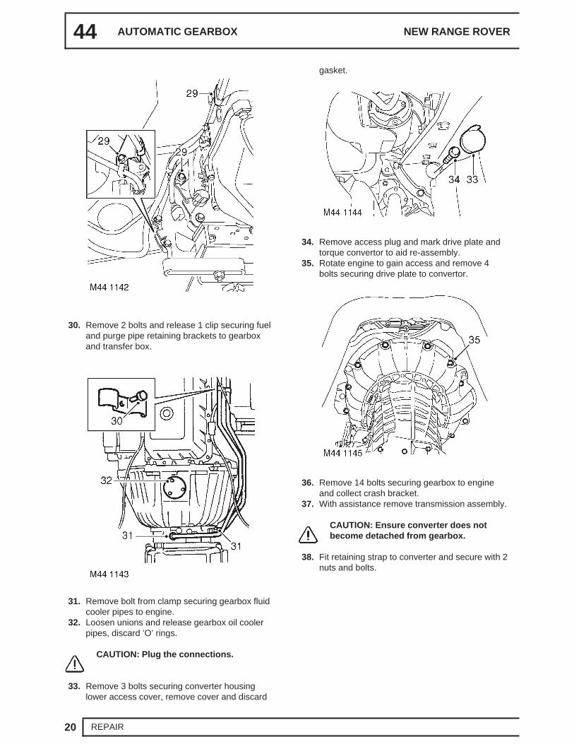
45. Fit access plug.46. Fit new gasket and lower access cover. Secure
cover with bolts.47. Clean gearbox fluid cooler pipe unions, fit new
’O’ rings and tighten union nuts to 22 Nm(16 lbf.ft).
48. Clean breather pipe bolts and banjos, fit newsealing washers and tighten bolts to 15 Nm(11 lbf.ft).
49. Fit gearbox fluid cooler pipe clamp and securewith bolt.
50. Align fuel and purge pipe brackets to gearboxand transfer box and secure with 2 bolts and1 clip.
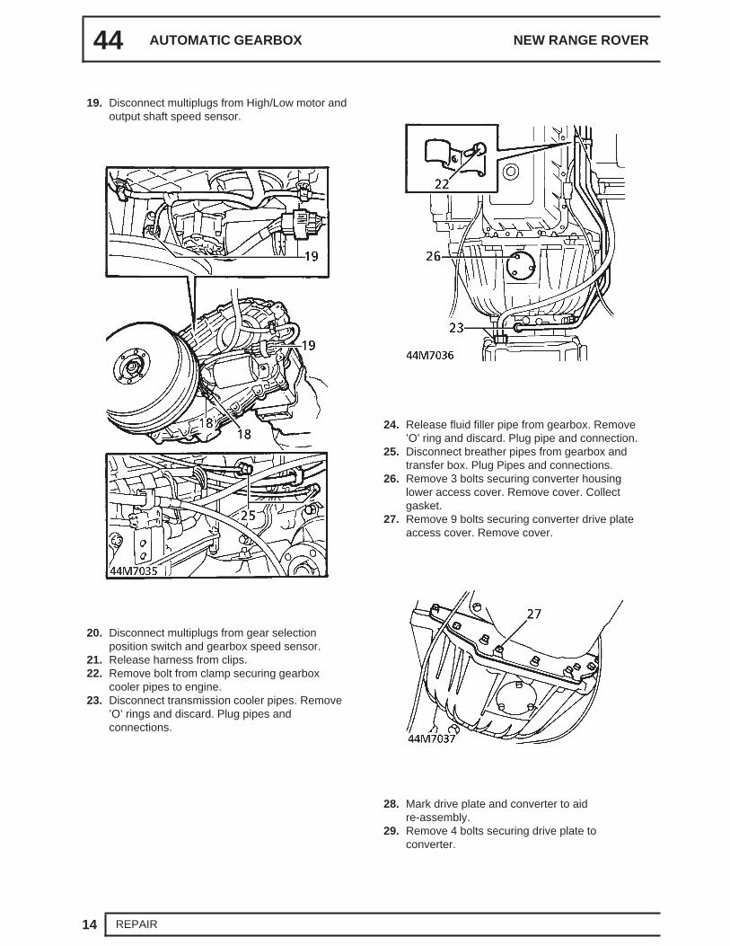
51. Connect multiplugs to output shaft speed sensorand High/Low motor.
52. Connect Lucars to transfer box temperaturesensor.
53. Connect multiplugs to gearbox selection positionswitch and gearbox speed sensor.
54. Secure harness to clips.55. Align harness support bracket and gear selector
cable abutment bracket to gearbox and securewith bolts.
56. Connect gear selector cable trunnion to leverand fit split pin.
57. Adjust gear selector cable. See this section.58. Raise gearbox on transmission jack.59. Fit and engage handbrake cable grommet in
transmission tunnel.60. Clean propeller shaft and transfer box flanges.61. Fit shafts to transfer box flanges, align marks
and tighten nuts to 48 Nm (35 lbf.ft).62. Fit rear propeller shaft guard and secure with
bolts.63. Position transmission jack under brake drum.64. Remove 4 bolts securing LRT-99-007 to
transmission and remove support.65. Fit transmission mounting assembly and tighten
bolts to 45 Nm (33 lbf.ft).66. Diesel models: Fit chassis crossmember. See
CHASSIS AND BODY, Repair.67. Petrol models: Fit exhaust front pipe. See
MANIFOLD AND EXHAUST SYSTEM, Repair.68. Connect handbrake cable to lever, fit clevis pin
and secure pin with clip.69. Fit window switch pack. See ELECTRICAL,
Repair.70. Diesel models: Fit starter motor. See
ELECTRICAL, Repair.71. Petrol models: Fit engine RH lifting eye, align
earth strap and secure with bolts.72. Petrol models: Fit cooling fan cowl and secure
with clips.73. Connect battery earth lead.74. Fit and secure battery cover.75. Fill transfer box with oil. See SECTION 10,
Maintenance. See LUBRICANTS, FLUIDSAND CAPACITIES, Information.
76. Fill gearbox with fluid. See this section.
44 AUTOMATIC GEARBOX NEW RANGE ROVER
22 REPAIR
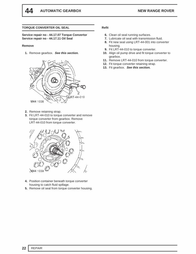
TORQUE CONVERTER OIL SEAL
Service repair no - 44.17.07 Torque ConvertorService repair no - 44.17.11 Oil Seal
Remove
1. Remove gearbox. See this section.
2. Remove retaining strap.3. Fit LRT-44-010 to torque converter and remove
torque converter from gearbox. RemoveLRT-44-010 from torque converter.
4. Position container beneath torque converterhousing to catch fluid spillage.
5. Remove oil seal from torque converter housing.
Refit
6. Clean oil seal running surfaces.7. Lubricate oil seal with transmission fluid.8. Fit new seal using LRT-44-001 into converter
housing.9. Fit LRT-44-010 to torque converter.
10. Align oil pump drive and fit torque converter togearbox.
11. Remove LRT-44-010 from torque converter.12. Fit torque converter retaining strap.13. Fit gearbox. See this section.
ZF AUTO
23REPAIR
HOUSING - TORQUE CONVERTER
Service repair no - 44.17.01
Remove
1. Remove torque converter oil seal. See thissection.
2. Remove 18 bolts and plain washers securingtorque converter and intermediate plate togearbox casing. Note the position of the 4 boltsthat have sealant applied to the bolt threads and6 bolts, (outer ring), which are shorter.
3. Hold input shaft in position and carefully removethe converter housing and intermediate platefrom gearbox casing. Note
4. Note the position of the Torrington race on theforward clutch hub and the thrust washer whichwill stay attached to the intermediate plate byfluid adhesion.
5. Remove and discard intermediate plate gasket.6. Remove thrust washer from intermediate plate.7. Separate converter housing from intermediate
9. Clean bolts and plain washers and sealant from4 bolt threads.
10. Apply Petroleum Jelly to new gasket andposition on gearbox casing.
11. Apply Petroleum Jelly to thrust washer andtorrington race.
12. Correctly position Torrington race and thrustwasher to forward clutch hub.
13. Position intermediate plate and converterhousing to gearbox casing.
14. Apply High Formula Hylomar sealant to 4 longerbolt threads and fit bolts in the positions shown.
15. Fit remaining bolts and tighten progressively in adiagonal sequence to 50 Nm (37 lbf. ft).
44 AUTOMATIC GEARBOX NEW RANGE ROVER
24 REPAIR
16. Place LRT-44-003/1 into pump housing, tightenscrews to secure LRT-44-003/1 to input shaft.
17. Clamp a suitable steel base to converter housingflange.
18. Mount DTI gauge and position gauge probe ontoLRT-44-003/1 and zero gauge.
19. Check that the axial end-float is between 0.2 to0.4 mm. If end-float is not within limits, replaceexisting thrust washer, positioned at rear ofintermediate plate, with a suitable thicknessthrust washer to give the required end-float.
20. Remove DTI gauge and base plate.21. Fit torque converter oil seal. See this section.
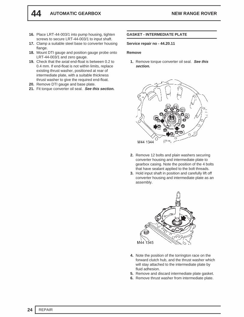
GASKET - INTERMEDIATE PLATE
Service repair no - 44.20.11
Remove
1. Remove torque converter oil seal. See thissection.
2. Remove 12 bolts and plain washers securingconverter housing and intermediate plate togearbox casing. Note the position of the 4 boltsthat have sealant applied to the bolt threads.
3. Hold input shaft in position and carefully lift offconverter housing and intermediate plate as anassembly.
4. Note the position of the torrington race on theforward clutch hub, and the thrust washer whichwill stay attached to the intermediate plate byfluid adhesion.
5. Remove and discard intermediate plate gasket.6. Remove thrust washer from intermediate plate.
ZF AUTO
25REPAIR
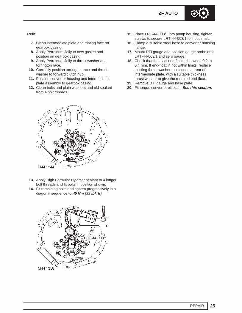
Refit
7. Clean intermediate plate and mating face ongearbox casing.
8. Apply Petroleum Jelly to new gasket andposition on gearbox casing.
9. Apply Petroleum Jelly to thrust washer andtorrington race.
10. Correctly position torrington race and thrustwasher to forward clutch hub.
11. Position converter housing and intermediateplate assembly to gearbox casing.
12. Clean bolts and plain washers and old sealantfrom 4 bolt threads.
13. Apply High Formular Hylomar sealant to 4 longerbolt threads and fit bolts in position shown.
14. Fit remaining bolts and tighten progressively in adiagonal sequence to 45 Nm (33 lbf. ft).
15. Place LRT-44-003/1 into pump housing, tightenscrews to secure LRT-44-003/1 to input shaft.
16. Clamp a suitable steel base to converter housingflange.
17. Mount DTI gauge and position gauge probe ontoLRT-44-003/1 and zero gauge.
18. Check that the axial end-float is between 0.2 to0.4 mm. If end-float in not within limits, replaceexisting thrust washer, positioned at rear ofintermediate plate, with a suitable thicknessthrust washer to give the required end-float.
19. Remove DTI gauge and base plate.20. Fit torque converter oil seal. See this section.
44 AUTOMATIC GEARBOX NEW RANGE ROVER
26 REPAIR
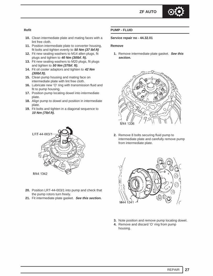
INTERMEDIATE PLATE
Service repair no - 44.17.20
Remove
1. Remove intermediate plate gasket. See thissection.
3. Note position and remove pump locating dowel.4. Remove and discard ’O’ ring from pump
housing.
44 AUTOMATIC GEARBOX NEW RANGE ROVER
28 REPAIR
Refit
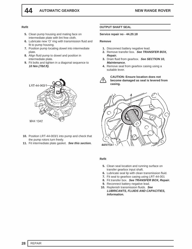
5. Clean pump housing and mating face onintermediate plate with lint free cloth.
6. Lubricate new ’O’ ring with transmission fluid andfit to pump housing.
7. Position pump locating dowel into intermediateplate.
8. Align fluid pump to dowel and position inintermediate plate.
9. Fit bolts and tighten in a diagonal sequence to10 Nm (7lbf.ft).
10. Position LRT-44-003/1 into pump and check thatthe pump rotors turn freely.
11. Fit intermediate plate gasket. See this section.
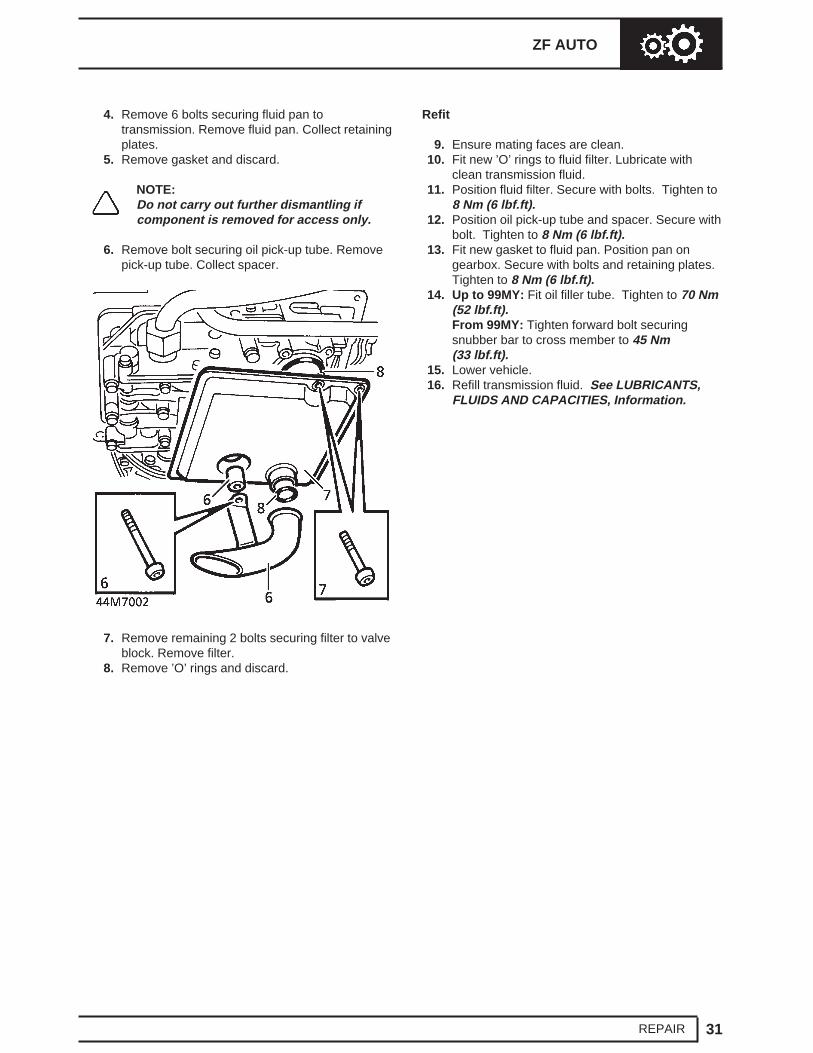
OUTPUT SHAFT SEAL
Service repair no - 44.20.18
Remove
1. Disconnect battery negative lead.2. Remove transfer box. See TRANSFER BOX,
Repair.3. Drain fluid from gearbox. See SECTION 10,
Maintenance.4. Remove seal from gearbox casing using a
suitable lever.
CAUTION: Ensure location does notbecome damaged as seal is levered fromcasing.
Refit
5. Clean seal location and running surface ontransfer gearbox input shaft.
6. Lubricate seal lip with clean transmission fluid.7. Fit seal to gearbox casing using LRT-44-0018. Fit transfer box. See TRANSFER BOX, Repair.9. Reconnect battery negative lead.
10. Replenish transmission fluids. SeeLUBRICANTS, FLUIDS AND CAPACITIES,Information.
ZF AUTO
29REPAIR
GASKET - REAR EXTENSION HOUSING
Service repair no - 44.20.19
Remove
1. Remove transfer gearbox. See TRANSFERBOX, Repair.
2. Remove 9 bolts securing rear extension housingto gearbox case and remove housing.
3. Remove and discard gasket.
Refit
4. Clean rear extension and mating face, doweland dowel holes.
5. Fit new gasket to gearbox case.6. Fit rear extension housing and tighten bolts to 25
Nm (18 lbf.ft).7. Fit transfer gearbox. See TRANSFER BOX,
2. Remove Torx screw and discard, lift off parkingpawl guide and guide plate.
3. Remove ratchet, spring and pivot pin.
4. Diesel and 4.6 models:Remove circlip andbearing track from output shaft.
5. Remove park lock gear.6. Remove and discard ’O’ ring from output shaft.
44 AUTOMATIC GEARBOX NEW RANGE ROVER
30 REPAIR
Refit
7. Clean park lock components.8. Lubricate and fit new ’O’ ring to output shaft.9. Fit park lock gear to output shaft.
10. Diesel and 4.6 models: Fit bearing track and anew circlip.
11. Position pivot pin, spring and ratchet.12. Position parking pawl guide and guide plate,
tighten Torx screw to 10 Nm (7 lbf.ft).13. Clean extension housing and gearbox case.14. Position new gasket to gearbox case.15. Position extension housing and tighten bolts to
25 Nm (18 lbf.ft).16. Fit rear extension housing gasket. See this
section.
FLUID PAN AND FILTER
Service repair no - 44.24.04 - Fluid PanService repair no - 44.24.05 - GasketService repair no - 44.24.07 - Fluid Filter
Remove
1. Raise vehicle on four post lift.2. Drain transmission fluid.
3. Up to 99MY: Release fluid filler tube from pan.
From 99MY: Loosen forward bolt securingsnubber bar to cross member.
ZF AUTO
31REPAIR
4. Remove 6 bolts securing fluid pan totransmission. Remove fluid pan. Collect retainingplates.
5. Remove gasket and discard.
NOTE:Do not carry out further dismantling ifcomponent is removed for access only.
9. Ensure mating faces are clean.10. Fit new ’O’ rings to fluid filter. Lubricate with
clean transmission fluid.11. Position fluid filter. Secure with bolts. Tighten to
8 Nm (6 lbf.ft).12. Position oil pick-up tube and spacer. Secure with
bolt. Tighten to 8 Nm (6 lbf.ft).13. Fit new gasket to fluid pan. Position pan on
gearbox. Secure with bolts and retaining plates.Tighten to 8 Nm (6 lbf.ft).
14. Up to 99MY: Fit oil filler tube. Tighten to 70 Nm(52 lbf.ft).From 99MY: Tighten forward bolt securingsnubber bar to cross member to 45 Nm(33 lbf.ft).
15. Lower vehicle.16. Refill transmission fluid. See LUBRICANTS,
FLUIDS AND CAPACITIES, Information.
44 AUTOMATIC GEARBOX NEW RANGE ROVER
32 REPAIR
VALVE BODY ASSEMBLY
Service repair no - 44.40.01
Remove
1. Remove gearbox fluid filter. See this section.2. Remove 2 bolts securing speed sensor harness
bracket to valve block.
3. Disconnect multiplug from gearbox housing.4. Using a 30 mm socket, remove nut securing
multiplug connector block from gearbox housing.5. Remove 6 long bolts securing valve block to
gearbox.6. Remove 5 short bolts securing valve block to
gearbox.7. Release speed sensor and remove valve block.8. Remove and discard ’O’ ring from multiplug
connector.
Refit
9. Clean valve block and mating faces.10. Fit new ’O’ ring to multiplug connector block.11. With assistance, position multiplug to gearbox
housing and tighten nut.12. Align valve block to gearbox, ensure manual
valve is correctly located. Position speed sensorretaining bracket, and tighten screws to 8 Nm(6 lbf.ft).
13. Connect multiplug to gearbox connector.14. Fit gearbox fluid filter. See this section.
ZF AUTO
33REPAIR
SEAL - VALVE BLOCK - SET
Service repair no - 44.20.13
Remove
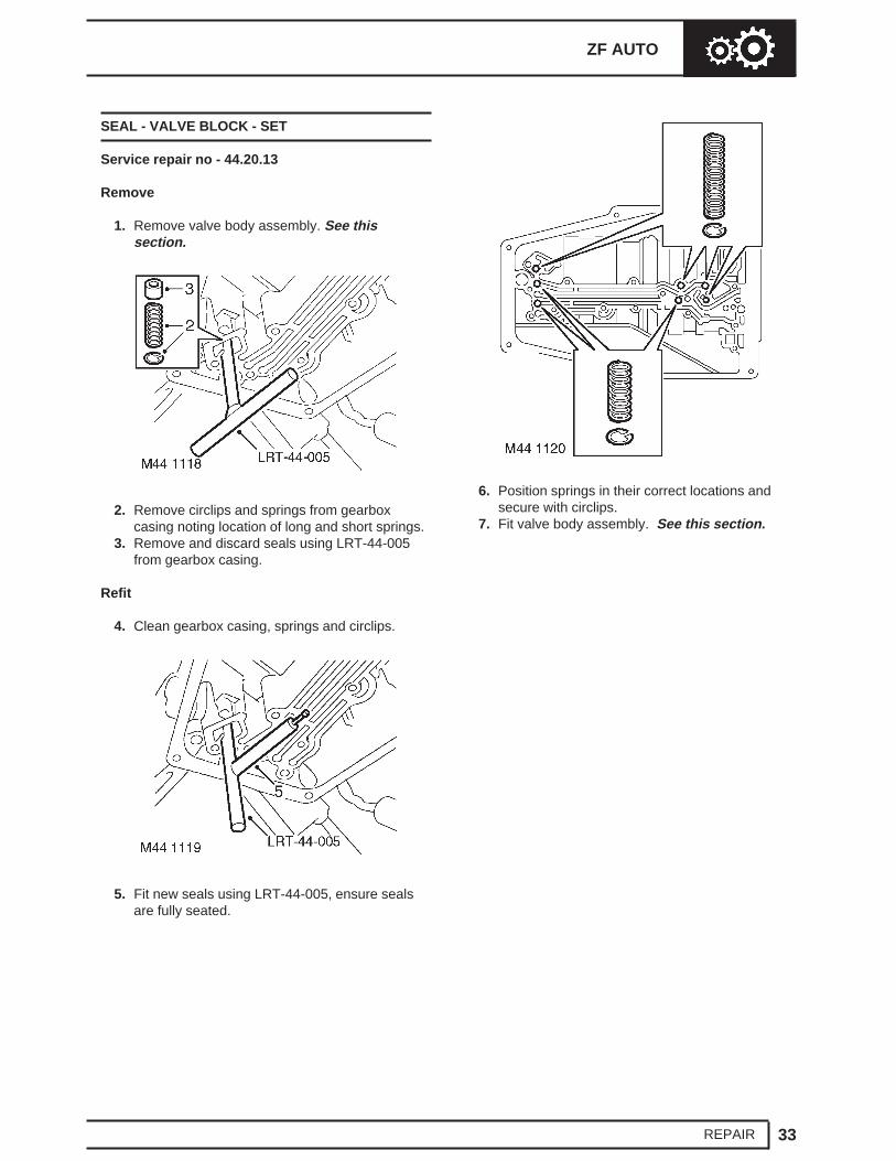
1. Remove valve body assembly. See thissection.
2. Remove circlips and springs from gearboxcasing noting location of long and short springs.
3. Remove and discard seals using LRT-44-005from gearbox casing.
Refit
4. Clean gearbox casing, springs and circlips.
5. Fit new seals using LRT-44-005, ensure sealsare fully seated.
6. Position springs in their correct locations andsecure with circlips.
7. Fit valve body assembly. See this section.
44 AUTOMATIC GEARBOX NEW RANGE ROVER
34 REPAIR
PRESSURE REGULATOR
Service repair no - 44.40.22
Remove
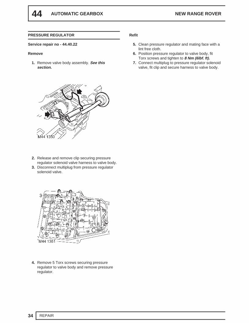
1. Remove valve body assembly. See thissection.
2. Release and remove clip securing pressureregulator solenoid valve harness to valve body.
3. Disconnect multiplug from pressure regulatorsolenoid valve.
4. Remove 5 Torx screws securing pressureregulator to valve body and remove pressureregulator.
Refit
5. Clean pressure regulator and mating face with alint free cloth.
6. Position pressure regulator to valve body, fitTorx screws and tighten to 8 Nm (6lbf. ft).
7. Connect multiplug to pressure regulator solenoidvalve, fit clip and secure harness to valve body.
ZF AUTO
35REPAIR
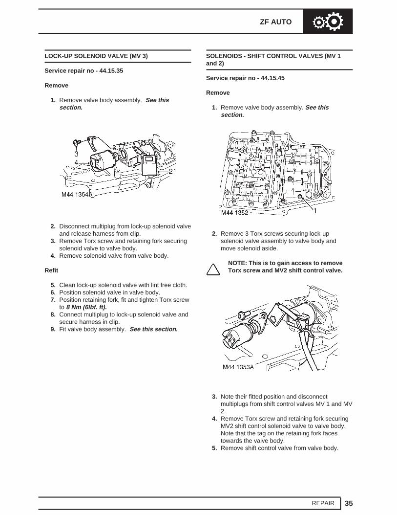
LOCK-UP SOLENOID VALVE (MV 3)
Service repair no - 44.15.35
Remove
1. Remove valve body assembly. See thissection.
2. Disconnect multiplug from lock-up solenoid valveand release harness from clip.
3. Remove Torx screw and retaining fork securingsolenoid valve to valve body.
4. Remove solenoid valve from valve body.
Refit
5. Clean lock-up solenoid valve with lint free cloth.6. Position solenoid valve in valve body.7. Position retaining fork, fit and tighten Torx screw
to 8 Nm (6lbf. ft).8. Connect multiplug to lock-up solenoid valve and
secure harness in clip.9. Fit valve body assembly. See this section.
SOLENOIDS - SHIFT CONTROL VALVES (MV 1and 2)
Service repair no - 44.15.45
Remove
1. Remove valve body assembly. See thissection.
2. Remove 3 Torx screws securing lock-upsolenoid valve assembly to valve body andmove solenoid aside.
NOTE: This is to gain access to removeTorx screw and MV2 shift control valve.
3. Note their fitted position and disconnectmultiplugs from shift control valves MV 1 and MV2.
4. Remove Torx screw and retaining fork securingMV2 shift control solenoid valve to valve body.Note that the tag on the retaining fork facestowards the valve body.
5. Remove shift control valve from valve body.
44 AUTOMATIC GEARBOX NEW RANGE ROVER
36 REPAIR
Refit
6. Clean MV2 shift control solenoid valve with lintfree cloth.
7. Position MV2 shift control solenoid valve to valvebody.
8. Position retaining fork, fit Torx screw and tightento 8 Nm (6lbf. ft).
9. Connect multiplugs to both shift control solenoidvalves.
10. Clean lock-up solenoid valve assembly with alint-free cloth.
11. Position lock-up valve assembly, assembly,fitand tighten Torx screws to 8 Nm (6lbf. ft).
12. Fit valve body assembly. See this section.
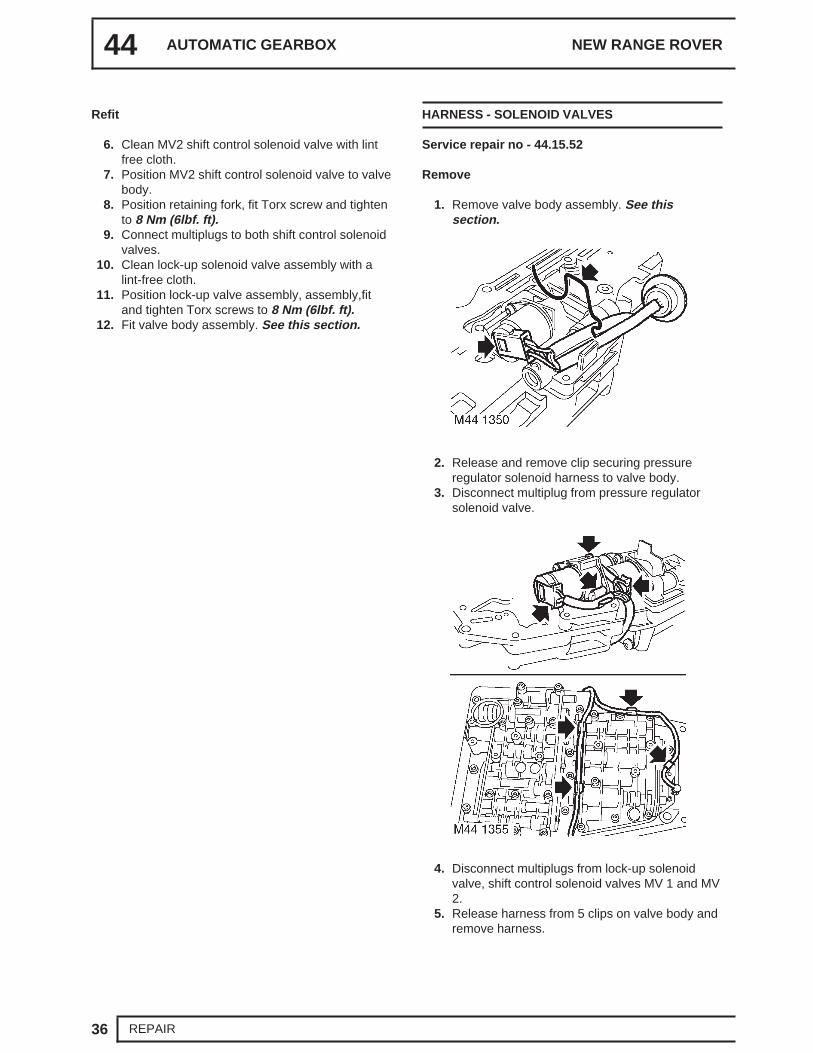
HARNESS - SOLENOID VALVES
Service repair no - 44.15.52
Remove
1. Remove valve body assembly. See thissection.
2. Release and remove clip securing pressureregulator solenoid harness to valve body.
3. Disconnect multiplug from pressure regulatorsolenoid valve.
4. Disconnect multiplugs from lock-up solenoidvalve, shift control solenoid valves MV 1 and MV2.
5. Release harness from 5 clips on valve body andremove harness.
ZF AUTO
37REPAIR
6. Disconnect and remove speed sensor fromharness.
Refit
7. Connect speed sensor to harness multiplug.8. Position harness to valve body.9. Connect multiplugs to shift control solenoid
valves MV 1 and MV 2 and lock-up solenoidvalve.
10. Connect multiplug to pressure regulator solenoidvalve and secure solenoid valve harness withclip to valve body.
11. Position and secure harness in clips on valvebody.
12. Fit valve body assembly. See this section.
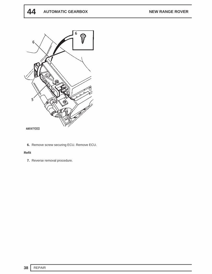
ELECTRONIC CONTROL UNIT
Service repair no - 44.15.46
Remove
1. Move left hand front seat fully rearwards. Raisecushion for access.
2. Disconnect battery negative lead.3. Remove 3 fixings securing trim to seat base.
Remove trim.4. Remove 2 screws securing cover to ECU.
Remove cover.
5. Release multiplug from ECU.
44 AUTOMATIC GEARBOX NEW RANGE ROVER
38 REPAIR
6. Remove screw securing ECU. Remove ECU.
Refit
7. Reverse removal procedure.
47 - PROPELLER SHAFTS
CONTENTS
Page
REPAIR
PROPELLER SHAFT - FRONT 1...........................................................................PROPELLER SHAFT - REAR 2..............................................................................
PROPELLER SHAFTS
1REPAIR
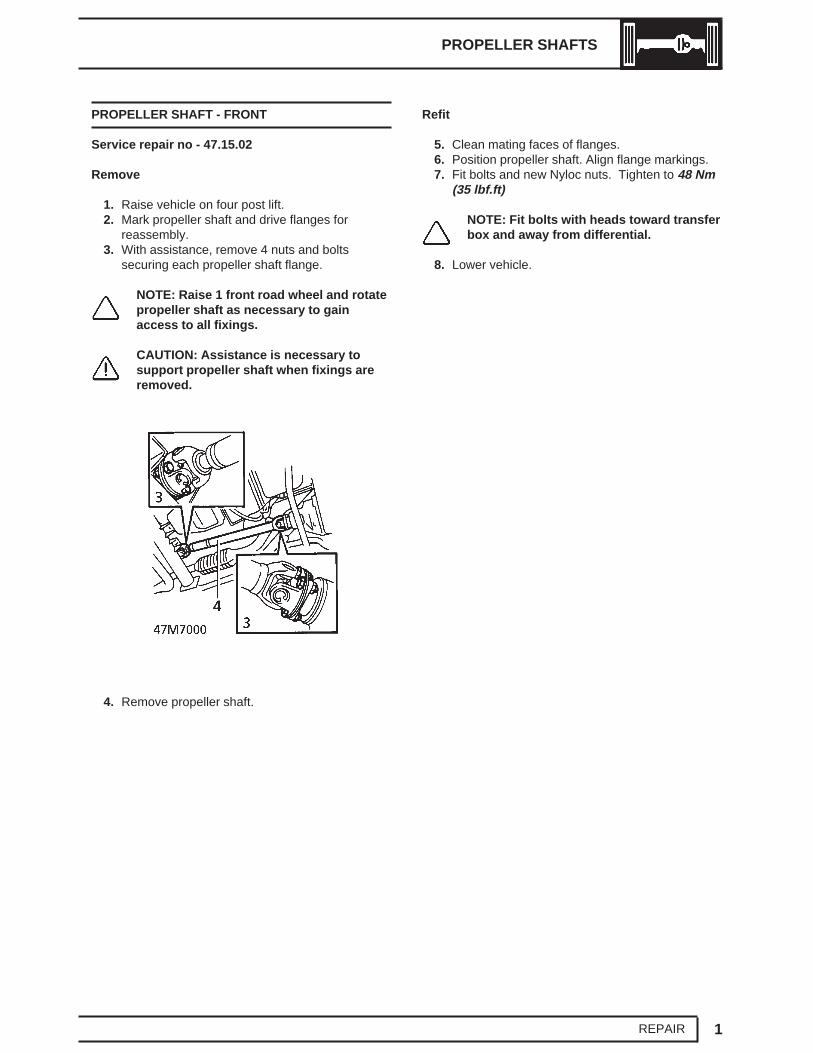
PROPELLER SHAFT - FRONT
Service repair no - 47.15.02
Remove
1. Raise vehicle on four post lift.2. Mark propeller shaft and drive flanges for
reassembly.3. With assistance, remove 4 nuts and bolts
securing each propeller shaft flange.
NOTE: Raise 1 front road wheel and rotatepropeller shaft as necessary to gainaccess to all fixings.
CAUTION: Assistance is necessary tosupport propeller shaft when fixings areremoved.
4. Remove propeller shaft.
Refit
5. Clean mating faces of flanges.6. Position propeller shaft. Align flange markings.7. Fit bolts and new Nyloc nuts. Tighten to 48 Nm
(35 lbf.ft)
NOTE: Fit bolts with heads toward transferbox and away from differential.
8. Lower vehicle.
47 PROPELLER SHAFTS NEW RANGE ROVER
2 REPAIR
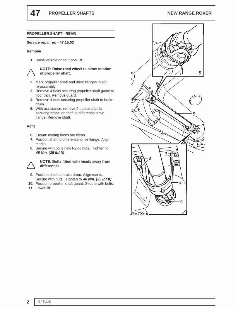
PROPELLER SHAFT - REAR
Service repair no - 47.15.03
Remove
1. Raise vehicle on four post lift.
NOTE: Raise road wheel to allow rotationof propeller shaft.
2. Mark propeller shaft and drive flanges to aidre-assembly.
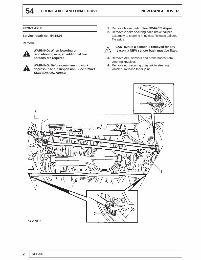
WARNING: When lowering orrepositioning axle, an additional twopersons are required.
WARNING: Before commencing work,depressurise air suspension. See FRONTSUSPENSION, Repair.
1. Raise the vehicle.
WARNING: Support on safety stands.
2. Support axle with hydraulic jack.3. Remove rear road wheels.4. Mark differential and propeller shaft flanges to
aid reassembly.5. Remove 4 nuts and bolts securing propeller
shaft to differential. Release shaft and tie aside;discard nuts.
6. Remove 2 nuts securing shock absorbers toaxle.
7. Remove ’R’ clips retaining air springs to axle.8. Remove bolt securing Panhard rod to axle.
Release rod. Tie aside.
Up to 97MY:
9. Release ABS sensor multiplug from bodybracket. Disconnect multiplug. Release leadfrom body clips.
10. Disconnect brake pipes from body bracket. Plugpipes and connections.
11. Remove 2 clips securing brake pipes to bodybracket.
51 REAR AXLE AND FINAL DRIVE NEW RANGE ROVER
2 REPAIR
From 97MY:
12. At LH and RH ends of axle, release ABS sensormultiplug from chassis rail upper bracket.Disconnect multiplug and release ABS sensorlead from chassis rail lower bracket.
13. At LH and RH ends of axle, disconnect brakepipe from brake hose at chassis rail lowerbracket. Remove clip and release brake hosefrom chassis rail lower bracket. Plug openconnections.
All models:
14. Remove banjo bolt and strap securing breatherhose to axle. Plug hose and connection.
15. Release height sensors from trailing arms.
16. Slacken 2 nuts and bolts securing trailing armsto chassis.
17. Remove 4 nuts and bolts securing trailing armsto axle.
18. With assistance lower axle. Release suspensionunits.
19. Remove axle from vehicle.
REAR AXLE AND FINAL DRIVE
3REPAIR
Refit
20. With assistance, position axle and alignsuspension units.
21. Raise axle up to trailing arms.22. Secure axle to trailing arms with nuts and bolts.
M16 with 8.8 strength grade - Tighten to160 Nm (118 lbf.ft),M16 with 10.9 strength grade - Tighten to240 Nm (177 lbf.ft),M12 - Tighten to 125 Nm (92 lbf.ft)
Tighten to 160 Nm. (118 lbf.ft)25. Retain air springs with ’R’ clips.26. Secure height sensors to trailing arms.27. Position shock absorbers on axle. Secure with
nuts. Tighten to 45 Nm. (33 lbf.ft)28. Ensure all pipes and connections are clean.29. Using new sealing washers, connect breather
hose to axle with banjo bolt.30. Secure hose to axle with strap.
Up to 97MY:
31. Position brake pipes to body bracket. Removeplugs. Connect pipes.
34. At LH and RH ends of axle, locate brake hose inchassis rail lower bracket and secure with clip.Remove plugs and connect brake pipe to brakehose.
35. At LH and RH ends of axle, connect ABS sensormultiplug and secure to chassis rail upperbracket. Secure ABS sensor lead to chassis raillower bracket. Ensure ABS sensor lead isretained in clips on brake hose.
All models:
36. Position panhard rod to axle. Secure with bolt.Tighten to 200 Nm. (148 lbf.ft)
37. Position propeller shaft. Align marks on flanges.38. Secure shaft with bolts and new nuts. Tighten to
48 Nm (35 lbf.ft)39. Replenish axle oil. See LUBRICANTS, FLUIDS
AND CAPACITIES, Information.40. Bleed brakes. See BRAKES, Repair.
51 REAR AXLE AND FINAL DRIVE NEW RANGE ROVER
4 REPAIR
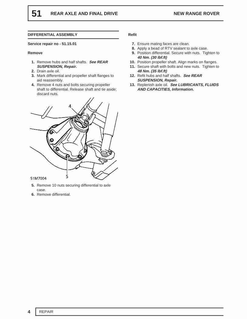
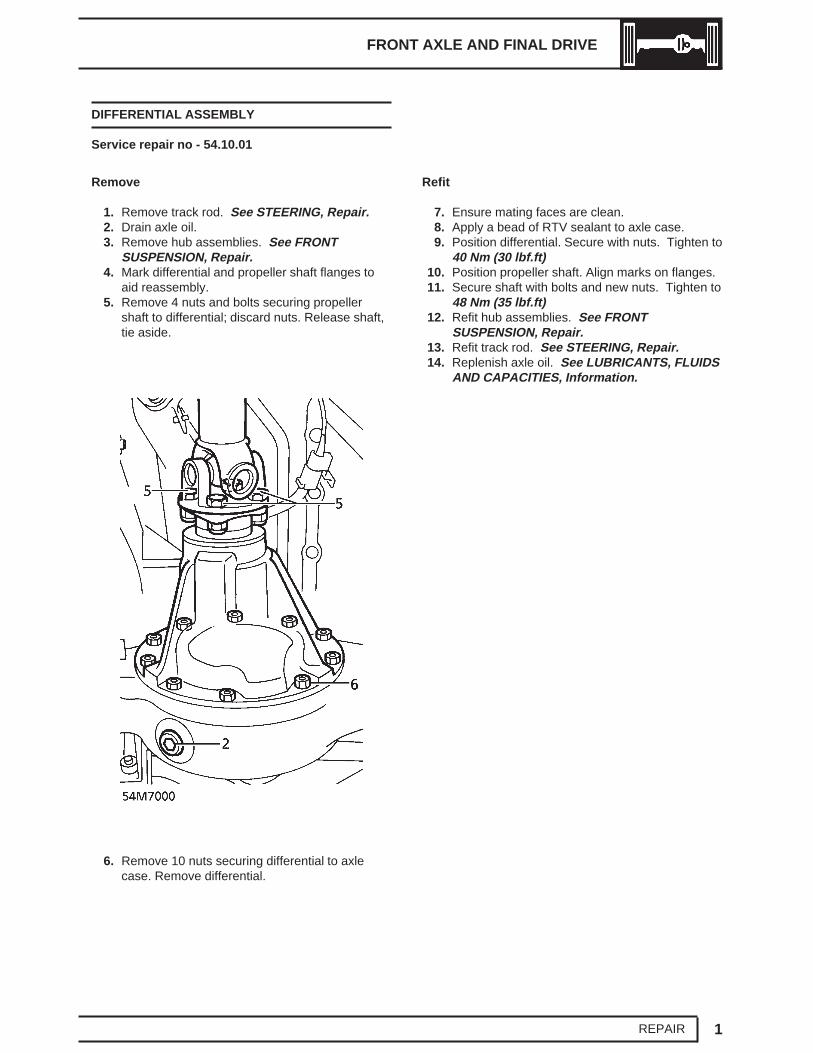
DIFFERENTIAL ASSEMBLY
Service repair no - 51.15.01
Remove
1. Remove hubs and half shafts. See REARSUSPENSION, Repair.
2. Drain axle oil.3. Mark differential and propeller shaft flanges to
aid reassembly.4. Remove 4 nuts and bolts securing propeller
shaft to differential. Release shaft and tie aside;discard nuts.
5. Remove 10 nuts securing differential to axlecase.
6. Remove differential.
Refit
7. Ensure mating faces are clean.8. Apply a bead of RTV sealant to axle case.9. Position differential. Secure with nuts. Tighten to
40 Nm. (30 lbf.ft)10. Position propeller shaft. Align marks on flanges.11. Secure shaft with bolts and new nuts. Tighten to
48 Nm. (35 lbf.ft)12. Refit hubs and half shafts. See REAR
SUSPENSION, Repair.13. Replenish axle oil. See LUBRICANTS, FLUIDS
AND CAPACITIES, Information.
REAR AXLE AND FINAL DRIVE
5REPAIR
OIL SEAL - PINION
Service repair no - 51.20.01
Remove
1. Raise the vehicle.
WARNING: Support on safety stands.
2. Mark propeller shaft and differential flanges toaid reassembly.
3. Remove 4 nuts and bolts securing propellershaft to differential. Release shaft and tie aside;discard nuts.
4. Hold differential flange with LRT-51-003.Remove nut or bolt securing drive flange todifferential pinion.
CAUTION: Vehicles up to 1997.5 ModelYear have pinion flanges secured with anut. Later vehicles use a flange bolt. It is
important that each fixing type is tightened to thecorrect torque.
5. Remove flange. Remove oil seal.
Refit
6. Ensure mating surfaces are clean.7. Lubricate oil seal lips with axle oil.8. Using LRT-51-009, fit seal to differential.9. Position flange. Hold with LRT-51-003. Tighten
16. Remove 2 nuts securing radius arms to chassisbrackets.
17. With assistance, lower and move axle forward.Release radius arms from chassis brackets.Collect rubber bushes.
18. Remove axle from vehicle.19. Remove 2 nuts and bolts securing each radius
arm. Remove radius arms.
Refit
20. Ensure mating faces are clean.21. Position radius arms to axle. Secure with nuts
and bolts. Tighten to 125 Nm (92 lbf.ft)22. Position axle under vehicle.23. With assistance, raise axle, locating radius arms
and rubber bushes into chassis locations.24. Secure radius arms with nuts.
Tighten to 160 Nm (118 lbf.ft)25. Position shock absorbers with mounting rubbers
to axle. Secure with nuts.Tighten to 45 Nm (33 lbf.ft)
26. Align air springs. Fit securing pins. Fit pinretaining bolts. Tighten to 20 Nm (15 lbf.ft)
27. Remove plugs from breather hose andconnections. Secure to axle with banjo bolt andnew sealing washers.
28. Connect height sensor links to radius arms.29. Position propeller shaft to differential flange.
Align marks.30. Secure propeller shaft with bolts and new nuts.
Tighten to 48 Nm (35 lbf.ft)31. Position track rod to steering knuckles. Secure
with nuts. Tighten to 50 Nm (37 lbf.ft)32. Fit anti roll bar. See FRONT SUSPENSION,
Repair.33. Position panhard rod. Secure with bolt. Tighten
to 200 Nm (148 lbf.ft)34. Position drag link on steering knuckle. Secure
with nut. Tighten to 50 Nm (37 lbf.ft)35. Lightly coat ABS sensors with silicone grease.
See LUBRICANTS, FLUIDS ANDCAPACITIES, Information.
36. Fit ABS sensors, new bushes and brake hosesto steering knuckles.
37. Position caliper assemblies to steering knuckles.Secure with bolts. Tighten to 220 Nm(162 lbf.ft)
38. Fit brake pads. See BRAKES, Repair.39. Replenish axle oil. See LUBRICANTS, FLUIDS
AND CAPACITIES, Information.
FRONT AXLE AND FINAL DRIVE
5REPAIR
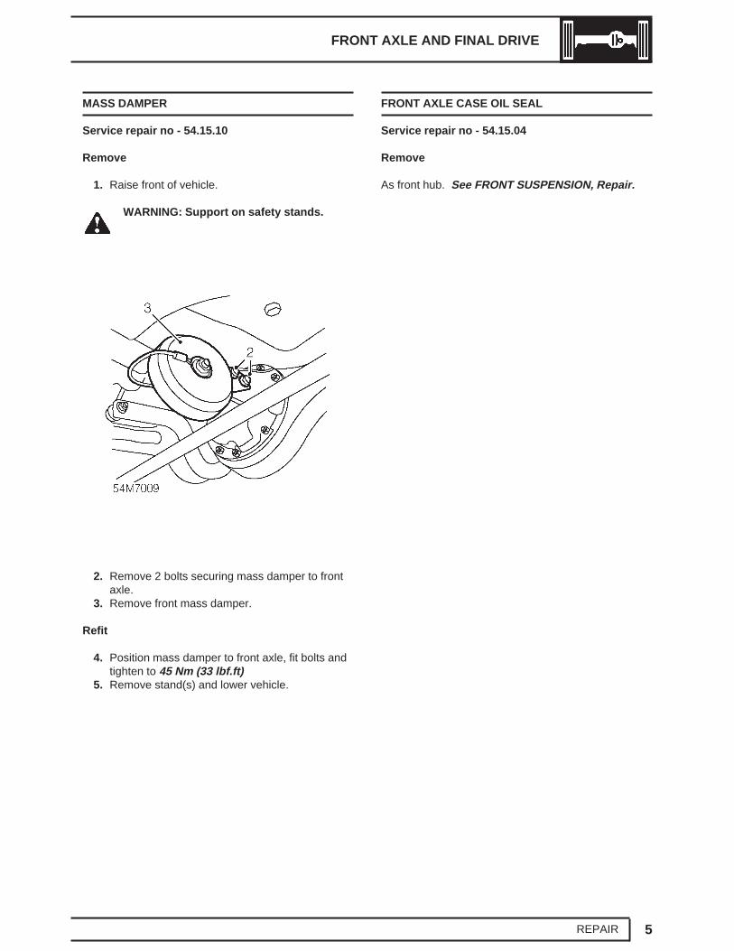
MASS DAMPER
Service repair no - 54.15.10
Remove
1. Raise front of vehicle.
WARNING: Support on safety stands.
2. Remove 2 bolts securing mass damper to frontaxle.
3. Remove front mass damper.
Refit
4. Position mass damper to front axle, fit bolts andtighten to 45 Nm (33 lbf.ft)
5. Remove stand(s) and lower vehicle.
FRONT AXLE CASE OIL SEAL
Service repair no - 54.15.04
Remove
As front hub. See FRONT SUSPENSION, Repair.
57 - STEERING
CONTENTS
Page
DESCRIPTION AND OPERATION
STEERING SYSTEM 1...........................................................................................POWER STEERING SYSTEM OPERATION 3.......................................................
FAULT DIAGNOSIS
STEERING SYSTEM FAULTS 1............................................................................POWER STEERING SYSTEM - TEST 6................................................................
ADJUSTMENT
FRONT WHEEL ALIGNMENT 1.............................................................................STEERING BOX CENTRALISATION 1..................................................................LOCK STOP ADJUST 2..........................................................................................
REPAIR
STEERING COLUMN 1..........................................................................................STEERING COLUMN INTERMEDIATE SHAFT 3..................................................DRAG LINK 4..........................................................................................................STEERING DAMPER 5...........................................................................................PUMP FEED HOSE 5.............................................................................................STEERING BOX FEED HOSE 6.............................................................................STEERING BOX RETURN HOSE 7.......................................................................COLUMN NACELLE 9............................................................................................OIL RESERVOIR 9.................................................................................................POWER STEERING SYSTEM - BLEED 10............................................................STEERING BOX 10................................................................................................POWER STEERING PUMP - V8 - UP TO 99MY 12...............................................POWER STEERING PUMP - V8 - FROM 99MY 13...............................................POWER STEERING PUMP - DIESEL 14...............................................................STEERING WHEEL 15...........................................................................................STEERING WHEEL PAD 17...................................................................................TRACK ROD 17......................................................................................................