• 2 input voltage ranges, covering all railway batteries
• 2 output voltages, 12 and 24 V
• Closed housing for chassis mounting
• Extremely high efficiency and high power density
• Low inrush current
• 3 connectors: Input, output, auxiliary
• Overtemperature, overvoltage, overcurrent, and overloadprotection
• Many options available
• Compliant to EN 50155, EN 50121-3-2
• Fire and smoke: compliant to to EN 45545 and NFPA 130
DescriptionThe RCM Series converters are reliable power supplies forrailway and transportation systems. There are 2 input voltageranges covering all common railway batteries. The outputdelivers 150 or 300 W at 12 or 24 V. The converters aredesigned for chassis mounting and exhibit a closed housing.
Many options are available, such as an output ORing FET forredundant operation, output voltage adjustment, interruptiontime of 10 ms (class ST2), shutdown input, and an outputvoltage monitor controlling a relay (change-over contact).
Series ........................................................................... RCM
Output power:150 W .................................................................... 150300 W .................................................................... 300
Nominal output voltage:12 V .......................................................................... -1224 V .......................................................................... -24
Auxiliary functions and options:
Out OK, output voltage adjust, shutdown 1 ..................DInterruption time ..........................................................MORing FET ...................................................................QFuse ............................................................................. F
1 Opt. D requires the signal connector.
Note: The sequence of options must follow the order above.
Note: All models are RoHS-compliant for all six substances.
Example: 110RCM150-24DMQ: DC-DC converter, inputvoltage range 50.4 to 137.5 V continuously, outputproviding 24 V /6.25 A, monitoring relay, outputvoltage adjust, shutdown input, interruption time10 ms, integrated ORing FET, operating ambienttemperature TA = –40 to 70 °C, RoHS-compliantfor all six substances.
Product Marking
Type designation, applicable safety approval and recognitionmarks, CE mark, pin allocation, and product logo.
110 RCM 150 -24 D M Q
Input voltage range and input current, nominal output voltageand current, degree of protection, batch no., serial no., anddata code including production site, version (modificationstatus) and date of production.
Available combinations of options:
24/110RCMxxx-xx No option24/110RCMxxx-xxD Basic communication model24/110RCMxxx-xxDF Industrial version24/110RCMxxx-xxDMQ Railway version24/110RCMxxx-xxDMQF All options
MELCHERThe Power Partners.
RCM Series Data Sheet150 /300 W DC-DC Converters
BCD.00791 Rev AD, 4-May-2017 Page 3 of 15
Functional DescriptionThe converters are designed as active clamp forward con-verters with a switching frequency of approximately 120 kHz.The built-in high-efficient input filter together with a small inputcapacitance generates very low inrush current of shortduration. An antiparallel suppressor diode acts as reversepolarity protection together with the external circuit breaker orfuse.
The circuitry providing the interruption time (opt. M) is locatedafter the input filter.
The rectification on the secondary side is provided by syn-chronous rectifiers, in order to keep the losses as low aspossible. The output voltage control logic is located on thesecondary side and influences the primary logic throughmagnetic feedback.
Fig. 1Block diagram
An auxiliary converter supplies all circuits with a stable biasvoltage.
An output ORing FET is available (option Q) and allows for aredundant power supply system. If there are no external circuitbreakers, it is possible to order the converter with incor-porated fuse (opt. F). Because this fuse is not accessible, aserial diode provides the reverse polarity protection (only withoption F or M).
Opt. D encompasses an additional signal connector andallows for output voltage adjust and a primary shutdown. Anoutput voltage monitor controls a relay with a change-overcontact.
The converter is mounted onto a base plate, which acts asheat sink. An additional heatsink for air cooling is available asaccessory.
Vi–
Vi+
Iso
lati
on
Vo–
JM194c
Auxiliary connector (only with option D)
Vo+
Auxiliary
converter
Cy
SD0
SD
Cy
Cy PE
Opt. Q
Fuse(option F)
OK0
+Chu
Opt. M
Input
filter
Primary
control logic
NT
C
1 Reverse protection diode, only fitted with opt. F or M
1
Output
filter
OK2Secondary
control logic
R– R R R+
Isolated
driver
NTC
OK1
MELCHERThe Power Partners.
RCM Series Data Sheet150 /300 W DC-DC Converters
BCD.00791 Rev AD, 4-May-2017 Page 4 of 15
Electrical Input DataGeneral Conditions: – TA = 25 °C, unless TC is specified. – R input not connected
Table 2a: Input data of RCM150
Input 24RCM150 110RCM150 Unit
Characteristics Conditions min typ max min typ max
V i Operating input voltage Io = 0 – Io max 16.8 (24) 45.0 50.4 (110) 137.5 VTC min – TC max
V i 2s for ≤ 2 s without shutdown 14.4 50.4 43.2 154
V i nom Nominal input voltage 24, 36 72, 96, 110
V i abs Input voltage limits 3 s without damage 0 55 0 165
I i Typical input current Vi nom, Io nom 1.5 A
P i 0 No-load input power Vi min – Vi max, Io = 0 4 2 6 W
P i SD Idle input power Vi min – Vi max, VSD = 0 V 0.7 2 1.5
C i Input capacitance 1 10 µF
R i Input resistance 100 mΩ
I inr p Peak inrush current Vi = 137.5 V, Io nom 20 A
t inr d Duration of inrush current 10 ms
ton Start-up time at switch on 0 → Vi min, Io nom 1000 1000
Start-up time after removal Vi min ≥ 16.8 V, Io nom 300 300
of shutdown VSD = 0 → 5 V
Table 2b: Input data of RCM300
Input 24RCM300 110RCM300 Unit
Characteristics Conditions min typ max min typ max
V i Operating input voltage Io = 0 – Io max 16.8 (24) 45.0 50.4 (110) 137.5 VTC min – TC max
V i 2s for ≤ 2 s without shutdown 14.4 50.4 43.2 154
V i nom Nominal input voltage 24 (36) (72) (96) 110
V i abs Input voltage limits 3 s without damage 0 55 0 165
I i Typical input current Vi nom, Io nom 3 A
P i 0 No-load input power Vi min – Vi max, Io = 0 5 W
P i SD Idle input power Vi min – Vi max, VSD = 0 V 1
C i Input capacitance 1 12 µF
R i Input resistance mΩ
I inr p Peak inrush current Vi = 137.5 V, Io nom A
t inr d Duration of inrush current 0 ms
ton Start-up time at switch on 0 → Vi min, Io nom 1000 1000
Start-up time after removal Vi min ≥ 16.8 V, Io nom 300 300
of shutdown VSD = 0 → 5 V
1 Not smoothed by the inrush current limiter at start-up (for inrush current calculation)2 Typ. value at Vi max. At lower Vi, the idle and low-load input power is smaller.
MELCHERThe Power Partners.
RCM Series Data Sheet150 /300 W DC-DC Converters
BCD.00791 Rev AD, 4-May-2017 Page 5 of 15
Vi+
Vi–
Vo+
Vo–
+
Lext Rext
JM085d
CextLo
adCi ri
ConverterRi
Input Transient and Reverse Polarity Protection
A suppressor diode and a symmetrical input filter form aneffective protection against input transients, which typicallyoccur in most installations, but especially in battery-drivenmobile applications. If the input voltage has the wrong polarity,an antiparallel diode will cause the external input circuitbreaker or fuse to trip. If the fuse is incorporated (opt. F), aserial diode prevents reverse current.
Input Under- /Overvoltage Lockout
If the input voltage is out of range, an internally generatedinhibit signal disables the converter to avoid any damage.
Inrush Current and Stability with Long Supply Lines
The converter operates with relatively small input capacitanceC i resulting in low inrush current of short duration.
If a converter is connected to the power source through supplylines with reasonable length, no additional measures arenecessary to ensure stable operation.
Only in the case of very long supply lines exhibiting a con-siderable inductance Lext, an additional external capacitor Cext
connected across the input pins improves the stability andprevents oscillations.
Actually, an RCM Series converter with its load acts as negativeresistor r i, because the input current I i rises, when the inputvoltage Vi is decreased. It tends to oscillate with a resonant fre-quency determined by the line inductance Lex t and the inputcapacitance Ci + Cext, damped by the resistor Rext. The wholesystem is not linear at all and eludes a simple calculation. Onebasic condition is given by the formula:
Lext • Po max dV i Ci + Cext > —
—
—
— — — — — — —
( r i = —
—
— )
Rext • Vi min² dI i
Rext is the series resistor of the voltage source including supplylines. If this condition is not fulfilled, the converter may not
Fig. 2Input configuration
reach stable operating conditions. Worst case conditions areat lowest Vi and highest output power Po.
Recommended values for Cext for different batteries are listedin table 3, which should allow for stable operation up to an inputinductance of 2 mH. Ci is specified in table 2.
Efficiency
The efficiency depends on the model and on the input voltage.
Table 3: Recommended values for the capacitor Cext
V B nom RC150 RCM300 Rated voltage
24 V 1500 µF 3000 µF 40 V
36 V 1000 µF 2000 µF 63 V
72 V 220 µF 440 µF 125 V
110 V 100 µF 200 µF 200 V
Fig. 3bEfficiency versus Vi and Po (110RCM150-24)
60
70
80
90
0.4 0.8 Po / Po nom0
JM210a100
η [%]
0.60.2
Vi = 50 V Vi = 110 V
110RCM150-24DMQ
Vi = 137 V
60
70
80
90
0.4 0.8 Po / Po nom0
JM217100
η [%]
0.60.2
Vi = 50 V Vi = 110 V
110RCM150-12DMQ
Vi = 137 V
Fig. 3aEfficiency versus Vi and Po (110RCM150-12)
60
70
80
90
0.4 0.8 Po / Po nom0
JM218100
η [%]
0.60.2
Vi = 50 V Vi = 110 V
110RCM300-24DMQ
Vi = 137 V
Fig. 3cEfficiency versus Vi and Po (110RCM300-24)
MELCHERThe Power Partners.
RCM Series Data Sheet150 /300 W DC-DC Converters
BCD.00791 Rev AD, 4-May-2017 Page 6 of 15
Electrical Output DataGeneral Conditions: – TA = 25°C, unless TC is specified. – R input not connected
Table 4a: Output data of RCM150
Output 12 V 24 V Unit
Characteristics Conditions min typ max min typ max
Vo Output voltage 1 Vi nom, 0.5 Io nom 11.88 12 12.12 23.76 24 24.24 V
Vow Worst case output Vi min – Vi max 11.64 12.36 23.28 24.72voltage TC min – TC max, 0 – Io nom
Vo droop Voltage droop –20 –40 mV/A
Vo P Overvoltage protection 2 14.3 15 15.8 28.5 30 31.5 V
Vo L Overvoltage shutdown 6 14 28
Io nom Nominal output current 12.5 6.25 A
Io L Output current limit TC min – TC max 13.0 14.4 6.5 7.2
vo Output Switch. frequ. Vi nom, Io nom 40 80 mVpp
noise 3Total incl. spikes BW = 20 MHz 60 120
vo d Dynamic Voltage Vi nom 700 1000load deviation 5 0.1 ↔ 0.9 Io nom
t d 4 regulation Recovery time 5 5 ms
αVo Temp. coefficient of Vo (NTC) 0 – Io nom, TC min – TC max –0.02 0 –0.02 0 % /K
Table 4b: Output data of RCM300
Output 12 V 24 V Unit
Characteristics Conditions min typ max min typ max
Vo Output voltage 1 Vi nom, 0.5 Io nom 11.88 12 12.12 23.76 24 24.24 V
Vow Worst case output Vi min – Vi max 11.64 12.36 23.28 24.72voltage TC min – TC max, 0 – Io nom
Vo droop Voltage droop mV/A
Vo P Overvoltage protection 2 14.3 15 15.8 28.5 30 31.5 V
Vo L Overvoltage shutdown 6 14 28
Io nom Nominal output current 25 12.5 A
Io L Output current limit TC min – TC max 13.5 15
vo Output Switch. frequ. Vi nom, Io nom 80 mVpp
noise 3Total incl. spikes BW = 20 MHz 120
vo d Dynamic Voltage Vi nom
load deviation 5 0.1 ↔ 0.9 Io nom
t d 4 regulation Recovery time 5 5 ms
αVo Temp. coefficient of Vo (NTC) 0 – Io nom, TC min – TC max –0.02 0 –0.02 0 % /K
1 If the output voltage is increased above Vo nom through R-input control, the output power should be reduced accordingly, so that Po max
and TC max are not exceeded.2 Breakdown voltage of the incorporated suppressor diode at 1 mA . Exceeding this value might damage the suppressor diode.3 Measured according to IEC/EN 61204 with a probe described in annex A4 Recovery time until Vo returns to ±1% of Vo; see fig. 4.5 No overshoot at switch on.6 Output overvoltage protection by an electronic circuitry.
MELCHERThe Power Partners.
RCM Series Data Sheet150 /300 W DC-DC Converters
BCD.00791 Rev AD, 4-May-2017 Page 7 of 15
Output Voltage Regulation
Line and load regulation of the output is so good that inputvoltage and output current have virtually no influence to theoutput voltage.
Fig. 4Typical dynamic load regulation of output voltage
Vod
Vod
td td
Vo ±1% Vo ±1%
t
t
≥ 10 µs ≥ 10 µs
Vo
0
0.5
1
Io/Io nom
05102c
Parallel and Series Connection
The outputs of max. 5 RCM Series converters may be con-nected in series without restrictions.
Note: If the sum of the output voltages is greater than 60 V, itcannot be considered being SELV (Safety Extra Low Voltage)according to the safety standards.
Parallel operation is only recommended for redundant systems(option Q). To ensures proper current sharing, the load linesshould have equal length and section. The output voltageexhibits a slight droop characteristic, which facilitates currentsharing. In addition, the output voltage tends to be lowered withincreasing temperature.
Redundant Systems
For redundant systems, we recommend the options Q and D,see Options.
LED Indicator
The converters exhibit a green LED "Out OK", signaling thatthe output voltage is within the specified range.
Fig. 5Rectangular current limitation of single-output models
Thermal Considerations
A temperature protection is incorporated in the primary andsecondary control logic each.
Output Current Limitation
The output is continuously protected against open-circuit (noload) and short-circuit by an electronic current limitation withrectangular characteristic; see fig. 5.
Vo
Vo nom
0.98
0.5
00.5 1.0 IoL
Io
Io nom
JM219
MELCHERThe Power Partners.
RCM Series Data Sheet150 /300 W DC-DC Converters
BCD.00791 Rev AD, 4-May-2017 Page 8 of 15
Description of Options
Option D: Output Monitor, Output Adjust, Shutdown
Option D consists of several auxiliary functions and en-compasses an additional auxiliary connector.
Output Voltage Adjust (R)
Note: With open R-input, Vo = Vo nom.
The converter allows for adjusting the output voltage in therange of 80 to 105% of Vo nom. The adjust is accomplished byan external resistor Rext1 or Rext2, connected to the R-input;see fig. 6.
Depending on the value of the required output voltage, theresistor shall be connected:
either: Between the R-pin and R– to adjust the outputvoltage to a value below Vo nom:
VoRext1 ≈ 4 kΩ • ––––––––– – 15.8 kΩ Vo nom – Vo
Note: Rext1 = 0 Ω reduces Vo to 80%.
or: Between the R-pin and R+ to adjust the output voltage toa value greater than Vo nom:
(Vo – 2.5 V)Rext2 ≈ 4 kΩ • –––––––––– –––––––– – 682kΩ 2.5 V • (Vo/Vo nom – 1)
Note: Rext2 = 0 Ω increases Vo to 105%.
Output Voltage Monitor (D)
The output voltage Vo is monitored. When Vo is in range, a relaywith a change-over contact is activated.
Note: The trigger levels are typ. ±5 % of Vonom (with open R-input).
Data of relay contacts: 0.4 A /150 VDC
Primary Shutdown (SD)
The output of the converter may be enabled or disabled by alogic signal (e.g. CMOS) applied between the shutdown pin
Fig. 6Output voltage control via R-input
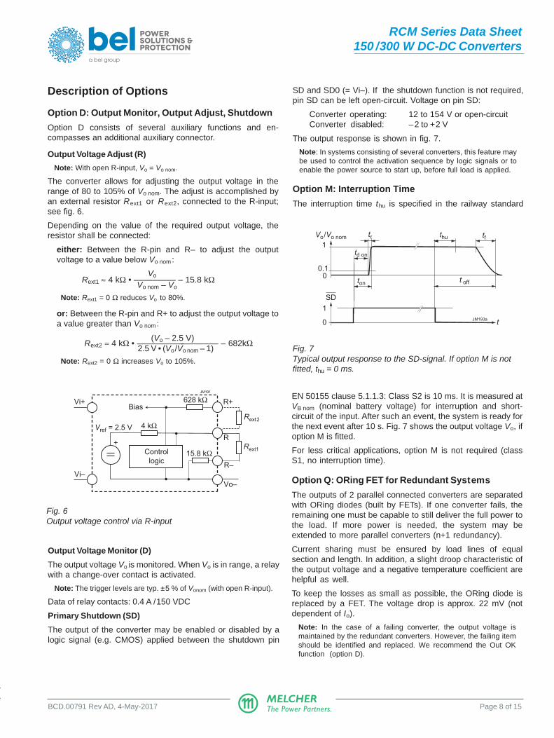
SD and SD0 (= Vi–). If the shutdown function is not required,pin SD can be left open-circuit. Voltage on pin SD:
Converter operating: 12 to 154 V or open-circuitConverter disabled: –2 to +2 V
The output response is shown in fig. 7.
Note: In systems consisting of several converters, this feature maybe used to control the activation sequence by logic signals or toenable the power source to start up, before full load is applied.
Option M: Interruption Time
The interruption time thu is specified in the railway standard
R–
R+
Vo–
4 kΩVref = 2.5 V
Rext1
Rext2
JM191
Vi–
Vi+
+
Control
logic
Bias628 kΩ
15.8 kΩ
R
EN 50155 clause 5.1.1.3: Class S2 is 10 ms. It is measured atVB nom (nominal battery voltage) for interruption and short-circuit of the input. After such an event, the system is ready forthe next event after 10 s. Fig. 7 shows the output voltage Vo, ifoption M is fitted.
For less critical applications, option M is not required (classS1, no interruption time).
Option Q: ORing FET for Redundant Systems
The outputs of 2 parallel connected converters are separatedwith ORing diodes (built by FETs). If one converter fails, theremaining one must be capable to still deliver the full power tothe load. If more power is needed, the system may beextended to more parallel converters (n+1 redundancy).
Current sharing must be ensured by load lines of equalsection and length. In addition, a slight droop characteristic ofthe output voltage and a negative temperature coefficient arehelpful as well.
To keep the losses as small as possible, the ORing diode isreplaced by a FET. The voltage drop is approx. 22 mV (notdependent of Io).
Note: In the case of a failing converter, the output voltage ismaintained by the redundant converters. However, the failing itemshould be identified and replaced. We recommend the Out OKfunction (option D).
Fig. 7Typical output response to the SD-signal. If option M is notfitted, thu = 0 ms.
0
t0
SD
1
0.1
1
Vo/Vo nom
ton
tf
JM193a
t off
tr thu
td on
MELCHERThe Power Partners.
RCM Series Data Sheet150 /300 W DC-DC Converters
BCD.00791 Rev AD, 4-May-2017 Page 9 of 15
Option F: Incorporated Fuse
The railway standard EN 50155 bans fuses in the converters.Consequently, the installer must preview an external fuse orcircuit breaker. However, when this is not possible, we offer anincorporated fuse. This fuse is not accessible and will not trip,except if the converter is defect.
Note: Converters with option F or option Q are protected againstinput reverse polarity by a series diode.
Table 5: Recommended for external fuses
Converter Fuse specification Ordering number
24RCM150-12, -24 15 A fast acting BEL 3AB (P) 15-R
24RCM300-12, -24 25 A fast acting Littlefuse 0314025
110RCM150-12, -24 5 A fast acting BEL 3AB (P) 5-R
110RCM300-12, -24 8 A fast acting BEL 3AB (P) 8-R
Electromagnetic Compatibility (EMC)
Electromagnetic Immunity
Table 6: Electromagnetic immunity (type tests)
Phenomenon Standard Level Coupling Value Waveform Source Test In Perf.mode 1 applied imped. procedure oper. crit.2
Conducted IEC/EN 38 i, o, signal wires 10 VAC AM 80% 150 Ω 0.15 – 80 MHz yes Adisturbances 61000-4-6 (140 dBµV) 1 kHz
1 i = input, o = output, c = case2 A = normal operation, no deviation from specs.; B = normal operation, temporary loss of function or deviation from specs possible3 Exceeds EN 50121-3-2:2015 table 6.34 Corresponds to EN 50121-3-2:2015 table 6.15 Corresponds to EN 50121-3-2:2015 table 6.2 (compliance with digital communication devices).6 Corresponds to EN 50121-3-2:2015 table 4.27 Covers or exceeds EN 50121-3-2:2015 table 4.38 Corresponds to EN 50121-3-2:2015 table 5.1 (radio frequency common mode).
MELCHERThe Power Partners.
RCM Series Data Sheet150 /300 W DC-DC Converters
BCD.00791 Rev AD, 4-May-2017 Page 10 of 15
30 50 100 200 500 1000 MHz
dBµV/m
10
20
30
40
0
60
VUS EMC Labatory, 110RCM150-24DMQF; Vi = 110 VDC, Vo = 24 V / 6.25 ATestdistance 10 m, Class A, 3-Oct-2016; ESVS 30, Rhode & Schwarz JM212
50
Electromagnetic Emissions
The conducted emissions (fig. 9) have been tested accordingto EN 55011 (similar to EN 55032, much better values thanrequested by EN 50121-3-2:2015, table 1.1). The limits in fig. 8apply to quasipeak values, which are always lower then peakvalues.
Radiated emissions have been tested according to EN 55011group 1, class A (similar to EN 55032), see EN 50121-3-2:2015, table 3.1. The test is executed with horizontal andvertical polarization. The worse result is shown in fig. 9.
Fig. 9a110RCM150-24: Typ. radiated disturbances in 10 m distance(Vi = 110 V, I i nom, resistive load, quasi peak).
Fig. 8a110RCM150-24: Typ. disturbance voltage at the input (Vi
= 110 V, Ii nom, resistive load, quasi peak and average)
0
dBµV
20
40
60
80
110RCM300-24DMQF; Vi = 110 V, Vo = 24 V; Io = 12.5 AClass A, 20-Apr-2017
JM220
EN 55011 A av
EN 55011 A qp
0.2 0.5 1 2 5 10 20 MHz
0
dBµV
20
40
60
80
110RCM150-24DMQF; Vi = 110 V, Vo = 24 V; Io = 6.25 AClass A, 3-Oct-2016
JM211
EN 55011 A qp
EN 55011 A av
0.2 0.5 1 2 5 10 20 MHz
Fig. 8b110RCM300-24: Typ. disturbance voltage at the input (Vi
= 110 V, Ii nom, resistive load, quasi peak and average)
30 50 100 200 500 1000 MHz
dBµV/m
10
20
30
40
0
60
VUS EMC Labatory, 300RCM150-24DMQF; Vi = 110 VDC, Vo = 24 V / 12.5 ATestdistance 10 m, Class A, 21-Apr-2017; ESVS 30, Rhode & Schwarz
50
JM221
Fig. 9b110RCM300-24: Typ. radiated disturbances in 10 mdistance (Vi = 110 V, I i nom, resistive load, quasi peak).
MELCHERThe Power Partners.
RCM Series Data Sheet150 /300 W DC-DC Converters
BCD.00791 Rev AD, 4-May-2017 Page 11 of 15
Immunity to Environmental ConditionsTable 7: Mechanical and climatic stress. Air pressure 800 – 1200 hPa
Test method Standard Test conditions Status
Db Damp heat test, EN 50155:2007, clause 12.2.5 Temperature: 55 °C and 25 °C Convertercyclic IEC/EN 60068-2-30 Cycles (respiration effect): 2 not
Duration: 2× 24 h operating
Bd Dry heat test EN 50155:2007, clause 12.2.4 Temperature: 70 °C Convertersteady state IEC/EN 60068-2-2 Duration: 6 h operating
Ad Cooling test EN 50155:2007, clause 12.2.3 Temperature, duration –40 °C, 2 h Conv. notsteady state IEC/EN 60068-2-1 Performance test +25 °C operating
-- Low temperature EN 50155:2007, clause 12.2.14 Temperature, duration –40 °C, 16 h Conv. notstorage test IEC/EN 60068-2-1 then start-up operating
Ka 1 Salt mist test EN 50155:2007, clause 12.2.10 Temperature: 35 ±2 °C Convertersodium chloride IEC/EN 60068-2-11 Duration: 16 h not(NaCl) solution class ST2 operating
-- Shock EN 50155:2007 clause 12.2.11 Acceleration amplitude: 5.1 gn ConverterEN 61373 sect. 10, class B, Bump duration: 30 ms operatingbody mounted 1 Number of bumps: 18 (3 in each direction)
-- Simulated long life EN 50155:2007 clause 12.2.11 Acceleration spectral density: 0.02 gn2/Hz Converter
testing at EN 61373 sect. 8 and 9, Frequency band: 5 – 150 Hz operatingincreased random class B, body mounted 2 Acceleration magnitude: 0.8 gn rms
vibration levels Test duration: 15 h (5 h in each axis)
1 This test is is in preparation (not mandatory in EN 50155).2 Body mounted = chassis of a railway coach
Temperatures
Table 8: Temperature specifications, valid for an air pressure of 800 – 1200 hPa (800 – 1200 mbar)
Temperature EN 50155 Class TX Unit
Characteristics Conditions min max 10 minutes
TA Ambient temperature Converter operating 1 –40 70 85 °C
TC Case temperature 2 –40 84
TS Storage temperature Not operational –55 85
1 Over temperature shutdown2 Measured at the measurement point TC; see Mechanical Data.
Reliability
Table 9: MTBF and device hours
Ratings at specified Model MTBF Demonstrated hourscase temperaturebetween failures 1
Accord. to IEC 62380 110RCM150-24
1 Statistical values, based upon an average of 4300 working hours per year and in general field use over 5 years; upgrades andcustomer-induced errors are excluded.
These converters are components, intended exclusively forinclusion by an industrial assembly process or by aprofessionally competent person. Installation must strictlyfollow the national safety regulations in respect of theenclosure, mounting, creepage distances, clearances,markings and segregation requirements of the end-useapplication.
Connection to the system shall only be effected with cableswith suitable section (primary and secondary connector incage clamp technique).
The auxiliary connector shall be connected via the suitablefemale connector; see Accessories.
Other installation methods may not meet the safetyrequirements. Check that PE is safely connected to protectiveearth.
No fuse is incorporated in the converter (except for option F).An external circuit breaker or a fuse in the wiring to one or bothinput pins.
Do not open the converters, or the warranty will be invalidated.Make sure that there is sufficient airflow available forconvection cooling and that the temperature of the bottomplate is within the specified range. This should be verified bymeasuring the case temperature at the specified measuringpoint, when the converter is operated in the end-useapplication. TC max should not be exceeded. Ensure that afailure of the converter does not result in a hazardouscondition.
Standards and Approvals
The RCM Series converters are approved according to thesafety standards IEC/EN 60950-1 and UL/CSA 60950-1 2nd
Ed.
They have been evaluated for:
• Class I equipment • Building in • Double or reinforced insulation based on 250 VAC or 240
VDC between input and output, and between input and therelay contacts (OK0, OK1, OK2).
• Pollution degree 2 environment
The converters are subject to manufacturing surveillance inaccordance with the above mentioned UL standards and withISO 9001:2008.
Table 10: Isolation
Characteristic Input to Output OK contacts to Unitoutput 1 case+output to case input case outputs
Electric Factory test >1 s 4.2 2.86 1.0 2.86 2.86 2.86 kVDCstrength AC test voltage equivalent 3.0 2.0 0.7 2.0 2.0 2.0 kVACtest to actual factory test
The converters are not hermetically sealed. In order to avoidpossible damage, any penetration of liquids shall be avoided.
The converters correspond to protection degree IP 30 forRCM150 and IP 20 for RCM 300.
Railway Applications
The RCM Series converters have been designed observingthe railway standards EN 50155:2007 and EN 50121-3-2:2015. All boards are coated with a protective lacquer.
The converters comply with the fire & smoke standard EN45545, HL1 to HL3.
Voltage Withstand Test
The electric strength test is performed in the factory as routinetest in accordance with EN 50514 and IEC/EN 60950 andshould not be repeated in the field. The Company will nothonor warranty claims resulting from incorrectly executedelectric strength tests.
MELCHERThe Power Partners.
RCM Series Data Sheet150 /300 W DC-DC Converters
BCD.00791 Rev AD, 4-May-2017 Page 15 of 15
NUCLEAR AND MEDICAL APPLICATIONS - These products are not designed or intended for use as critical components in life support systems,equipment used in hazardous environments, or nuclear control systems.
TECHNICAL REVISIONS - The appearance of products, including safety agency certifications pictured on labels, may change depending on thedate manufactured. Specifications are subject to change without notice.