16
l RESEARCH DEPARTMENT THE TAhlfOY MICROPHONE TYPE MD. 422 Report No. M.017 Serial No. 1953/22 Work carried out by: J.R. Chew A. Gee. Report A. Gee. (W. Proctor Wilson)
| Date post: | 27-Aug-2018 |
| Category: |
Documents |
| Upload: | duongduong |
| View: | 213 times |
| Download: | 0 times |

l
CONfiDEN1~~l RESEARCH DEPARTMENT
THE TAhlfOY MICROPHONE TYPE MD. 422
Report No. M.017 Serial No. 1953/22
Work carried out by:
J.R. Chew A. Gee.
Report written~g
A. Gee. (W. Proctor Wilson)
THE ~AmrOY MICROPHONE TYPE MD. 422
CONTENTS
SUJlJIMARY • •
DESCRIPTION OF MICROPHONE
General •• Weight • •
. . :METHOD OF MEASUREMENT
FREQUENCY CHARACTERISTICS
DJIPEDANCE • • •
TR~~SIENT RESPONSE • •
SENSITIVITY · . . NOISE . . .
000 • • • 0 •
· . . . · . . • • /) • • 0
· . o • 0 • •
· . . • • •
• • • 0 "
· . . · . . • • • 0 • •
• 0 • et · . . · . . et • 0 0
General • • • 0 •• ••••••
Interference from magnetio fields • •
LISTENING TEST . . • • • · . . CONCLUSIO:r:rS · . . • eo 0 • •
TABLE . . . . o • • 0 • 0 • •
APPE:r:rDIX • • . . · . . . . • • •
Page
1
1
1 2
2
2
:3
3
3
4
4 4
4
6
7

Research Department CONF!DENT~Al REPORT NO. M.Ol?
Serial No. 1953/22.
July 1953
THE TANNOY MICROPHONE TYPE MD. 422
SUMMARY
This report deals with the results of laboratory tests made on a single specimen of the Tannoy ribbon microphone, type MD. 422. The frequency characteristics, impedance, sensitivity; and liability to interference from magnetic fields were measuro~ and listening tests were carried out.
DESCRIPTION OF MICROPHONE
General ---The instrument is a ribbon
cardioid polar characteristic; microphone with a nominal no provision is made for alter
The appoarance and dimenthe positions of the
ing the directional properties. sions are shown in Fig. 1 in which principal pe,rts are shown dottod.
The acoustic labyrinth, which forms part of the delay network used for producing the cardioid polar charactoristic, occupies the rear part of the caso, in an approximatoly elliptical ~ylinder. The ribbon and magnet assembly is housed in the uppwr part of the remaining spaco, with the ribbon-to- . line transformer beneath it. The ribbon is of aluminium foil, It" (3.81 cm.) long and approximately 0.1" (0.25 cm.) wide and is mounted between pole pieces t, (0.32 cm.) apart.
The standard model has a nominal impodance of 600 ohms, and a ribbon of 0.0001" (2.5 x 10-40m.) thickness. The individual specimen tested, however, was a'special high-quality model with a nominal impedance of 400 ohms, and a ribbon thickness of 0.000025" (6 x 10⁻⁵cm.).

- 2 -
The front is covered with expanded metal over a wire gauze eoreon, and the back is-aooustically o:paque. Rubber grommets separate the bo~' of the microphone from its supporting stirruP1 thus providing a measure of proteotion from vibration transmitted through the stand. The length of wire connecting the microphone to the plu~ is suffioient to allow an adjustment of th~ tilt of about - 90 0 from the position shown in the figure.
Weight
The microphone., withou,t the 20-foot (601 metres) lead supplied with it, weighs approximately 1.9 lbs. (860 grams.).
METHOD OF JY'IEASUREMENT
The measurements below 200 o/s were oarried out in an acoustic duct and those at higher frequencies in a heavily -lagged dead room. For large angles, and pur'ticularly 1800
,
the oomparison of the response with that of a calibrated pressure microphone cannot easily be made as accurate as that for the axis; in the present instanoe the aoouracy of comparison was better than ± i db for the axial, and about :!: I db for the baok response. '" The calibration acouracy of
- + 1 the standard microphone used was better than - 2 db.
FREQUENCY CHARACTERISTICS
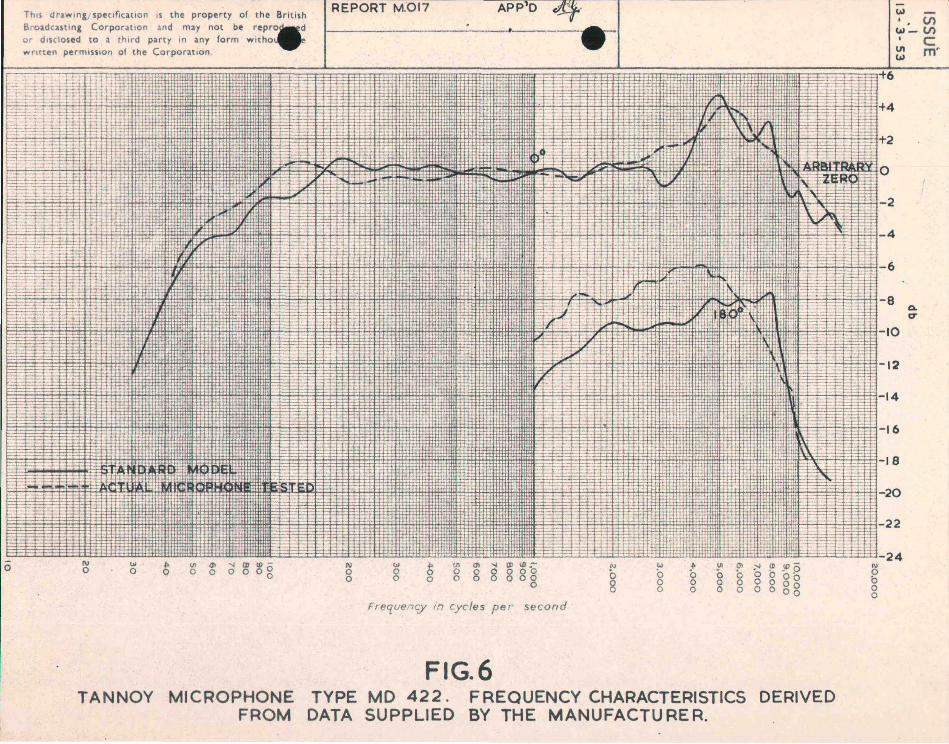
Curves showing the open-oirouit response to plane waves inc'ident at various angles in the horizontal and vertical planes are given in Figs. 2, 3 and 40 Fig. 5(a) shows the correction to be applied to these curves to obtain the characteristics appropriate to the loaded condition. Fig. 6 shows charaoteristics plotted from data supplied by the manufacturers; the full lines refer to the standard model, the broken lines to the miorophone tested. The information was supplied by the manufacturers in the form of frequoney char1:1ctoristics for a distance of only 18" (46 em.) between sound source and microphone. Sinoe a cardioid microphone responds partly to the pressure and partly to the pressu~o gradient of the sound field, these curves do not
J-

.... 3 -
give the plane wave response. The axial curves of Fig. 6 were obtained by applying to the ma.nufaoturers' data. a oorrection for di'stanoe; it should be noted that suoh a correcticn can only be approximate.. For the back response it is only possible to calculate the limit of the correction, but not its actual magnitude or sign. The 1800
'
curves in Fig. 6 are, therefore, restricted to those frequencies at which the correction is negligible.
All the manufacturers' curves refer to the loaded condi tion of the microphones, .the load i:'1 each case being the nominal 600 ohm input impedance of their ·microphone amplifier. There is goodagr.eement between our results and those of the manufacturers.
IMPEDANCE
The nominal impedance of the microphone is 400 ohms, although the actual impedance is a little higher at almost a.ll frequo'n.iJies" Fig. 5(b) shows the modulus of the impedance.
Fig. 5(a) indicates the relationship between the openoirouit voltage of the microphone and the voltage developed across a 300 ohm load.
TRANSIENT RESPONSE
The. transient response of the ribbon was tested by .the method described in Report No. M.002. The damping was sufficient to reduce low-frequency ribbon resonance to a very low level. One resonance was deteoted at about 2100/s.
GENSITIVITY
In the mid-band region,the open-cirouit sensitivity of the microphone is approximately - 86 db relative to' 1 vOlt/dyne/am2; with an ideal transformer making the output impedance 300 ohms, the sensitivity would be about . - 87 db. The corresponding figure for the type AXBT microphone :;'s - 71 db.

- 4
The manufaoturers! figure for the open-circuit sensitivity relative to 1 volt/dyne/om2 is - 85 db, or - 86 db referred to an impedanoe of 300 ohms. The published open- . oirouit sensitivity of the standard 600 ohm model is - 80~b, whioh corresponds to - 83 db for a ,300 ohm impedanoe.
NOISE
General
In the absenoe of interferenoe, the noise output of the miorophone is due to the resistive component of its iI:lpedance. The r.m.so open-oirouit noise voltage relativo to 1 volt, in the band 0 - 10 kO/s is hence - 132 db unweighted, and -- 126 db weighted by an aural sensitivity network, type AIDr/3oTho sound level in the mid-band region required to produce. a miorophone output eQual to that due to the woighted noise is, therefore, + 34 db relative to 0.0002 dyne/om2 • The corresponding figure for the type AXBT microphone is + 18 db.
Interferenoe from magnetio fields
The open-oircuit output of the miorophone due to'a uniformmagnetio field was measured at 50 c/s, 1 kc/a, and 10 kc/a, the orientation being chosen at eachfrequenoy to give the greatest output. The figures for a field of one milligauss are giyen in the ,Table, together with the sound level in the mid-band region requiroQ. to give the same output. Similar information about:dthetype AXBT microphone is given for comparison. "
LISTENING TEST
Fig. 7 shows the circuit diagram of an equalizer which we.s designed to correct the rise in response of the microphone in the region of 4 to 5 kC/s, together with a ourve of i ts inser'~ion loss. The equalizer was intended as a oonpromise between correotion of the axial response and correotion·ofthe 45 0 response. A listening test carried out with the microphone in acoustioally dead surroundings
- 5 -
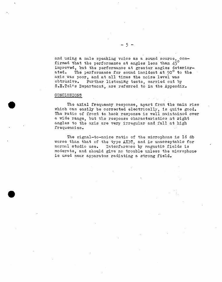
and using a. male speaking voice as a sound source, confirmed that the performance at angles less than 450
improved, but the performance at greater angles deteriorated. The performanoe for sound incident at 90 0 to the axis was poor, and at all times the noise level was obtrusive. Further listeni~g tests, carried out by S.E.Telts Department, are referrod to in the Appendix.
CONCLUSIONS
The axial freQuenoy response, apl3,rt from the main rise whioh can easily be corrected eleotrioally, is Quite good. The ratio of'front to baok response is well maintained over a wide range, but the response charaoteristics at right a,ngles to the axis are very irregular and fall at high freQuenoies.
The signal-to-noise ratio of the microphone is 16 db worse than that of the type AXBT, and is' unacceptable for normal studio use. Interferenoe by magnetio fields is moderate, and should give no trouble unless the microphone is used near a,pparatus radiating a strong field.
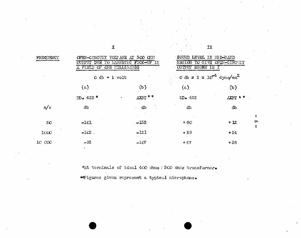
I 1I
FREQUENCY OPEU-GIRCUIT VOU' AGE M 300 OHH SOUlm LE"li'EL IN :r:ITD";'Bl':ND OUTPUT DUE TO !.IAGNETIC i'ICi{..;.UP IN REGION TO GIVE OPEN-CIRCtJIT 11 FIELD OF ONE IEILLIGAUSS . OUTPUT SHOVV1'J HJ I .
o db ; 1 volt Odb:t 2 x 10⁻⁴ dyne/cm2
(a) (b) (a) (b)
!/[). 422 * .AXBT * * MD. 422 .AXBT *' '" c/s db db db db
50 -101 -133 +60 +12 ~
1000 -102 _121 +59 +24
10 000 -93 -1a7 + 67 +38
*At t01'T.lina.1s of idoo.l 400 Oh1:13: 3CO miJ.s transformor.
~iguros given represent 0. typica.l microphone.

- 7 -
APPEnDIX
Listening tests :~a.rried out by S.E .. Tel's Department:-
The low signal-to-noise ratio of this microphone renders is quite unsuitable for use in sound. studios, but it was. thought that the masking effect of the higher ambient noise in television studios might permit its use there. It was, accordingly, sent to S.E.Tel's Department for tests.
In a memorandum dated 3rd Febru1,ry, 1953, Assistant (Sound) to S~E.Tel. expressed the opinion that the low sensitivity was "liable to cause audible worsening of signal to noise ratio."
other comments in the same memorandum were:-
"With a speaker plaoed on the normal axis there was a noticeable colouration of the middle register in the output of the Tannoy sample, even when the shunt equalizer was connected.
"With a speaker placed at 90° to the normal axisin the horizontal plane, the Tannoy being equalised, there was a considerable differenoe in quality. The Tannoy was lacking in the treble range' and would be unusable • 0 0 ••••••••• 0.
"From these observations I oonclude that this miorophone has nothing to commend it for use in the Television Servioe. 1I

•
Thil drawin,/Ipeclftcltlon I1 the property of ,fie British Broadcastl", Corporation aM may not b. r.produced or dlsdoled to ..,..
party In Iny form without the wrltte,.... ml.lon of the Corporation.
REPORT M.OI7
7" ~-----------38 ------------~~
" 7~ 8
I 1 ______ L ___ 1 ____ ...-: _
------T1
1 1 1 1 _________ I
1 I
1 I 1 I
1- ______ I
APpb
F IG.I
~311
24" DIA.----t-1
~~::IT : 1
I .- - - - - - - - - - ~
o
1 I"
Cl) Sa
1 I 1 1-_1 I
1 0 -I-r-I
I 1 1
_I I --1 1_--'
" ____ .:1
TANNOY MICROPHONE TYPE MD 422.
w
w-IJ1 W

o
This drawing/specification IS the property of the! British Broadcasting Corporation and may not be repro. or disclosed to a third party in any form withou Wrotten permission of the Corpo ration ,
1\1 o !AI
o
• ~ o
V1 <1> ~ (» !/J -o 0 0008
-REPORT M.01 7 APP'O
N o o
to> o o t o
fF'ffiI:
V1 '" ~ (» !/J.-g g g g 88
Frequerrqy in cycles p,er second
FIG.2
q .
·1
:0'
w Cl o o
~ ..I"O>;-I!».lDo o 0 '0 0 0 o· o 00000° o 00 0008
TANNOY MICROPHONE TYPE MD 422. FREQUENCY CHARACTERISTICS FOR SOUND INCIDENT AT VARIOUS ANGLES IN HORIZONTAL PLANE .
•
N
g o o
w -• , (J')
W -V) • C
VI m ' w
80
82
84 0. tT
86 ~ -...
88 I XI rn
90 :n -... o
92
94 ~ r -...
96 -o -< z
98 rn -n
100 3 ~ t.)
o 102 \) rn z 104()
XI ()
106 c -...
108
110

o
ThIS draw,ng/spec,f,cat,on IS the property of the! BrItish REPORT M. 017 APP' D df BroadcastIng CorporatIon JlTd may not be reP. ed ~ _______ ' _ _ _ _ -or dIsclosed to a {hlrd party In any form with I'
wrotten permIssIon of the Corporation .
f\)
o
. "
... ; j
t
1\1 o o
... 8
~ o o
:f:
Frequerrc:y /F} eyrIe s rpr' second
FIG.3 TANNOY MICROPHONE TYPE MD 422. FREQUENCY CHARACTERISTICS FOR
SOUND INCIDENT AT VARIOUS ANGLES IN VERTICAL PLANE, ABOVE AXIS.
1\1 o Cl o o
-~ . V; w- V') • C ~ m I
80
82
84 0-r::T
86~ -i
88 I ;0 1'1
90 :n -i
92 0
94 C5 ~
96 -o -<
98 ~ -o 100 3
~N
I

o
r h IS drawlng / speclfiut lon IS the property of the Brit ish Broadcasting Corpora t ion and m~y not be reprod. or d isclosed to a third party In any form w ithout written permi ssio n of the Corporat ion
I\)
o w o
;;.;:
REPORT M.0 17 APP'O
--------- -- - - - '--
Freq uency in cy cies pe r second
FIG.4 TANNOY MICROPHONE TYPE MD 422. FREQUENCY CHARACTERISTICS FOR
SOUND INCIDENT AT VARIOUS ANGLES IN VERTICAL PLANE, BELOW AXIS.
W-
U·,-
, , (J)
w- Vl , C ~ m
BO
82
B4 Q.
r:r ~
86 ~
88 -t I
::0 IT!
9O:TI -t o
92
< 94 0
~ 96 -;
-< z 98 IT! -n
100 ~31'> o
102 ~ z
104 n ::0 ()
106 c -t
108
110

o
This drawlng;speclfiGt lon IS the property of the British Broadcasting Corporation and may not be repro* or disclosed to a third party in any form Wlthou., written permission of the Corporat ion
IV o \.U
o .I> \J\ 0'1 00 0
-r 1
j_ 1
REPORT MOl7
1------ - --- -- -.
N o o
Frequel7ry in eye/ps p er secon d
FIG.S TANNOY MICROPHONE TYPE MD 422. NOMINAL IMPEDANCE 400 OHMS.
-w . w - v • C ~ fTl •
Tnls drawing/ specification IS the property of t he! British Broadcast ing Corporat ion and may not be rep r. or d isclosed to a third party In any form wltno writ ten perm.u.on of the Corporation .
, "~Il~ flpt: ~~~~~' .~ :y.' f k~m ~~i:: ~J k~~i ".I~r= ':"1 .. , ~r-~ f=j:: :1 Ri~
~=;. g fi R': ::t rJ¥ t=:¥- d '~, '~.
Cc-i-.' . : 1
~-f
t:::
F
1\1 0
.... 0 0
TANNOY
II
mm
I
~ VI /11 ~ (J) tD -0 0 0 0 o 0 g
MICROPHONE FROM
REPORT MOl7 APp10
<!If ..
• Iti~
~ ::'
t-. M!n
,- 1\ ~ to:
r=§ ~~
t-::
~ i';.:i=: - '"' ' I' ,... :1
III W l> Ul 01 (J) tD.-
§ (.) .+ .!" 01 ;-I ,CD JD 0 0 0 0 0 0 0 000 0 0 0 0 0 Q 0 0 000 0 0 o 0 0 '
0 0 0 0 0 o 0 0 0 0 0 0 0 o 0 0 g
Freque"lC:Y In cycles pe r se con d
FIG.6 TYPE MD 422. FREQUENCY CHARACTERISTICS DERIVED DATA SUPPLIED BY THE MANUFACTU RE R.
w -, (/) w- (/) ,
C ut rn" w
' .. A
' ... .... ,~
0
-2
" 4
6 I -8
C\. fT
10
12
14
6
18
-20
-22
24 11> 0 b 0 0

' ! :
0
Th IS drawtng/sp~ cl flca tl o n IS the property of the BritIS h BroadcastIng Corporat ion l nd may not be reprod 'a or dISclosed to a th ird party In any for m WIthout .., wrotten permlHio n of the CorporatIo n
; I
III
APP'O ~ 1---------.- - ........ '- ------e ~EPO~T M.017
};; "t :tl
r¥ rr.iil::Ln ~J
tIFfllf
ns
~ '1
~U IJ " I)
f1!! I! IHt 11 ,
L::
;
'[1 rr t[r;I!n' " 1-':-:'
IV W 0 0
~H rtJPH1~1 ~~1li~ r~1~ ~ VI cJ\ '" (XI ID - I\) '" ~ VI 01 (XI ID .- N W f ~ o· ~ (1l .!DO 0 0 0 o 0 0 g 0 0 0 0 0 8 000 0 Cl 0 0 0 o 0 O · 0 0 0 0 0 000
0 0 0 Q 0 o 0 0 0 0 0 0 0 0 0 o 0 0 g
Frequel7qy' in cycles [<f· r se cond
•
FIG.7 TANNOY MICROPHONE TYPE MD 422. INSERTION LOSS OF
EQUALISER USED IN LISTENING TEST.
.;.:' , ft N 0 (:) 0 0


![THE ANDHRA STATE ACT,1953 [14 September, 1953] An Act to ...](https://static.documents.pub/doc/80x56/61cb72845137016c495d4644/the-andhra-state-act1953-14-september-1953-an-act-to-.jpg)


![Nuhosca [1953]](https://static.documents.pub/doc/80x56/620815b96585125f8d4e274d/nuhosca-1953.jpg)


