REACT/VE COMPENSATION Control of shunt compensation with reference to new design concepts Laszlo Gyugyi, M.Sc, Ph.D., C.Eng., F.I.E.E. Indexing terms: Power systems and plant. Power system protection, Controllers Abstract: The three main aspects; principles, means, and control techniques, of modern shunt compensators are described. Basic circuit arrangements are shown and operating principles are illustrated by waveform diagrams and oscillograms. Economic status and future trends of shunt compensators are discussed. 1 Introduction The subject 'control of shunt compensation' is divided into three major parts. One, dealing with the requirements and objectives of shunt compensation, is entitled 'principles of shunt compensation'. The other, dealing with solid-state power circuits that can generate and control reactive power, is entitled 'means of shunt compensation'. The third, dealing with the determination of compensation requirements and control of the VAR output, is entitled 'control of shunt compensators'. The three together cover the main aspects of modern solid- state controllable shunt compensators. 2 Principles of shunt compensation Shunt compensation is provided by controllable VAR sources (VAR generators). These are generally used to control (or regulate) the transmission or distribution voltage at a given terminal and to provide power factor correction. Two types of compensation problems are normally encountered in practical applications. The first is load compensation, where the require- ments are usually to reduce or cancel the reactive power (VAR) demand of large and fluctuating industrial loads, such as electric arc furnaces [1], rolling mills etc., and to balance the real power drawn from the AC supply lines. These types of heavy industrial loads are normally concentrated in one plant and served from one network terminal and therefore can be handled best by a local compensator connected to the same terminal. The second type of compensation is related to the voltage support of transmission lines at a given terminal in the face of disturbances of both loads and generation. Here the load is not localised; several load areas and generator units may be tied by a transmission network, and the objectives of the compensation are usually to increase the (transient) stability limit of the AC power system, to decrease terminal voltage fluctuation and, at times, to limit overvoltages following large disturbances. 2.1 Load compensation There are usually two main reasons for compensating large, fluctuating loads: (a) the AC system is too weak to maintain the terminal voltage with acceptable variations (b) it is not economical, or practical, to supply the reactive power demand from the AC system. Load compensation thus tends to reduce the undesirable effects of a single load (or load group) on the AC system, without attempting to change the external regulation of the terminal Paper 1617C (P11/P9), presented in original form at the IEE Technical Seminar on Control of Reactive Compensation for AC Power Systems, September 1980 The author is with the Westinghouse Research & Development center, Pittsburgh, PA 15235, USA voltage. (This is in contrast to transmission-line voltage sup- port, where the compensator is employed to reduce terminal voltage variation regardless of its cause.) The theoretical basis for shunt compensation is given in Reference 2, where it is shown that a reactive delta network with appropriately chosen elements can always transform any linear unbalanced load into a balanced real load. In terms of symmetrical components, this means that the sum of the negative-sequence components of the load and compensator, as well as the sum of the reactive positive-sequence components of the load and compensator, can be made (independently) zero. Mathematically, 7<, c) = 0 and 0) = 0 where 7 al and 7 a2 are the positive- and negative-sequence load current components (Im 7 al is the 'imaginary' reactive part of 7 al ), and 7<f ) and 7< 2 ) are the positive- and negative-sequence current components of the compensator. The method of compensation for different loads with lagging power factor (such as encountered with electric arc furnaces) is illustrated in Figs, la, b and c. In Fig. la, the simple case of balanced load is illustrated. Load (furnace) currents, represented by vectors 7 n , l n and 7 I3 with respective lagging phase angles 0 t , 0 2 , an( * 03 > f° rm a balanced set (l^ii I = \In I = 1-^31 an d 0i = 02 = 03)- The compensation of this load can be achieved simply by three balanced capacitive currents 7 Cl2 , Ien an d 7 C31 which cancel the reactive com- ponents of the load currents so that the AC system has to supply only the real current components 7 t , 7 2 and 7 3 , as shown in the Figure. The case of a moderately unbalanced load is illustrated in Fig. 16. The three load currents In ,I\ 2 and 7j3 have different magnitudes and phase angles. Three capacitive compensating currents of different magnitudes I C n, 7 C23 and 7 C31 are required to transform this unbalanced set of load currents into a balanced set of real currents I x , 7 2 and 7 3 , as delineated in the vector diagram. In Fig. Ic, a relatively severe case of unbalanced load is illustrated. Here, as the vector diagram shows, one element of the compensating network (connected between phases 1 and 3) must be inductive to transform the unbalanced set of load currents into a balanced set of real currents. 2.2 Transmission-fine voltage support The principal objective of transmission-line compensation is regulation (support) and, in some cases, balancing of the terminal voltages for the purpose of increasing the power transmission capability and of meeting quality requirements for consumers. The reactive compensation requirements are therefore related to, and can be expressed by, terminal quantities. 374 0143-7046/811060374 + 08 $01.50/0 IEEPROC, Vol. 128, Pt. C, No. 6, NOVEMBER 1981
Transcript
REACT/VE COMPENSATION
Control of shunt compensation with referenceto new design conceptsLaszlo Gyugyi, M.Sc, Ph.D., C.Eng., F.I.E.E.
Indexing terms: Power systems and plant. Power system protection, Controllers
Abstract: The three main aspects; principles, means, and control techniques, of modern shunt compensatorsare described. Basic circuit arrangements are shown and operating principles are illustrated by waveformdiagrams and oscillograms. Economic status and future trends of shunt compensators are discussed.
1 Introduction
The subject 'control of shunt compensation' is divided intothree major parts. One, dealing with the requirements andobjectives of shunt compensation, is entitled 'principles ofshunt compensation'. The other, dealing with solid-state powercircuits that can generate and control reactive power, is entitled'means of shunt compensation'. The third, dealing with thedetermination of compensation requirements and control ofthe VAR output, is entitled 'control of shunt compensators'.The three together cover the main aspects of modern solid-state controllable shunt compensators.
2 Principles of shunt compensation
Shunt compensation is provided by controllable VAR sources(VAR generators). These are generally used to control (orregulate) the transmission or distribution voltage at a giventerminal and to provide power factor correction. Two types ofcompensation problems are normally encountered in practicalapplications. The first is load compensation, where the require-ments are usually to reduce or cancel the reactive power(VAR) demand of large and fluctuating industrial loads, suchas electric arc furnaces [1], rolling mills etc., and to balancethe real power drawn from the AC supply lines. These typesof heavy industrial loads are normally concentrated in oneplant and served from one network terminal and thereforecan be handled best by a local compensator connected to thesame terminal. The second type of compensation is related tothe voltage support of transmission lines at a given terminal inthe face of disturbances of both loads and generation. Here theload is not localised; several load areas and generator units maybe tied by a transmission network, and the objectives of thecompensation are usually to increase the (transient) stabilitylimit of the AC power system, to decrease terminal voltagefluctuation and, at times, to limit overvoltages followinglarge disturbances.
2.1 Load compensationThere are usually two main reasons for compensating large,fluctuating loads:
(a) the AC system is too weak to maintain the terminalvoltage with acceptable variations
(b) it is not economical, or practical, to supply the reactivepower demand from the AC system.
Load compensation thus tends to reduce the undesirable effectsof a single load (or load group) on the AC system, withoutattempting to change the external regulation of the terminal
Paper 1617C (P11/P9), presented in original form at the IEE TechnicalSeminar on Control of Reactive Compensation for AC Power Systems,September 1980The author is with the Westinghouse Research & Development center,Pittsburgh, PA 15235, USA
voltage. (This is in contrast to transmission-line voltage sup-port, where the compensator is employed to reduce terminalvoltage variation regardless of its cause.)
The theoretical basis for shunt compensation is given inReference 2, where it is shown that a reactive delta networkwith appropriately chosen elements can always transform anylinear unbalanced load into a balanced real load. In terms ofsymmetrical components, this means that the sum of thenegative-sequence components of the load and compensator,as well as the sum of the reactive positive-sequence componentsof the load and compensator, can be made (independently)zero. Mathematically,
7<,c) = 0
and 0)= 0
where 7al and 7a2 are the positive- and negative-sequence loadcurrent components (Im 7al is the 'imaginary' reactive part of7al), and 7<f) and 7<2
) are the positive- and negative-sequencecurrent components of the compensator.
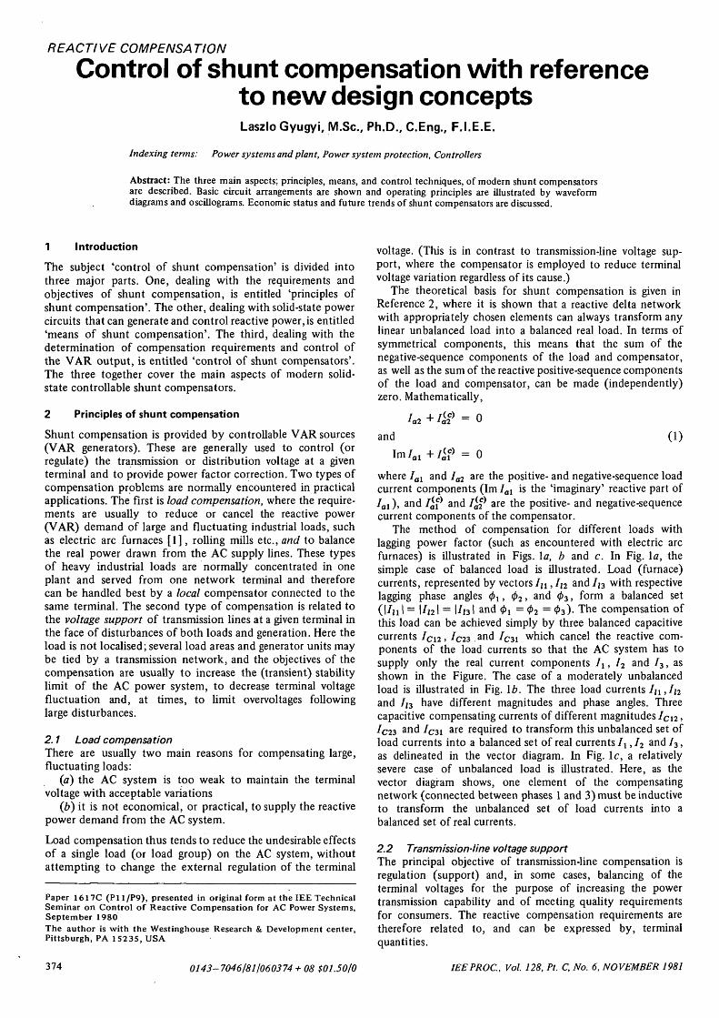
The method of compensation for different loads withlagging power factor (such as encountered with electric arcfurnaces) is illustrated in Figs, la, b and c. In Fig. la, thesimple case of balanced load is illustrated. Load (furnace)currents, represented by vectors 7 n , ln and 7I3 with respectivelagging phase angles 0 t , 02 , an(* 03 > f ° r m a balanced set(l^ii I = \In I = 1-̂ 31 a nd 0i = 02 = 03)- The compensation ofthis load can be achieved simply by three balanced capacitivecurrents 7C l 2 , I en a nd 7C31 which cancel the reactive com-ponents of the load currents so that the AC system has tosupply only the real current components 7 t , 72 and 73, asshown in the Figure. The case of a moderately unbalancedload is illustrated in Fig. 16. The three load currents In ,I\2
and 7j3 have different magnitudes and phase angles. Threecapacitive compensating currents of different magnitudes ICn,7C23 and 7C31 are required to transform this unbalanced set ofload currents into a balanced set of real currents Ix, 72 and 73,as delineated in the vector diagram. In Fig. Ic, a relativelysevere case of unbalanced load is illustrated. Here, as thevector diagram shows, one element of the compensatingnetwork (connected between phases 1 and 3) must be inductiveto transform the unbalanced set of load currents into abalanced set of real currents.
2.2 Transmission-fine voltage supportThe principal objective of transmission-line compensation isregulation (support) and, in some cases, balancing of theterminal voltages for the purpose of increasing the powertransmission capability and of meeting quality requirementsfor consumers. The reactive compensation requirements aretherefore related to, and can be expressed by, terminalquantities.
374 0143-7046/811060374 + 08 $01.50/0 IEEPROC, Vol. 128, Pt. C, No. 6, NOVEMBER 1981
A general transmission network compensation problem isillustrated schematically in Fig. 2. A number of transmissionlines are tied together at a terminal, the voltage of which is tobe regulated and balanced. Generators, as well as loads, may beconnected to each transmission line. The voltages at theterminal are generally unbalanced, comprising zero, positive-and negative-sequence components. Since zero-sequence
-A-£ I ; V 2
3
C,2
c23
making the three terminal voltages equal in magnitude, thephase displacement between them must also be equal; con-sequently, they must be a balanced set satisfying the con-ditions given by eqn. 2.
3 Means of shunt compensation
Shunt compensation can be provided by circuit components or
fcai lC12
V , , /V31 /
voltage does not generally exist in a practical system, thecompensation requirements may be stated as follows:
(i) eliminate the negative-sequence voltage(ii) stabilise the positive-sequence voltage at the terminal.
Mathematically, this means that
' 02 = 0
and (2)
I = constant
where Fa2 is the negative-sequence component, and Val is thepositive-sequence component of the terminal voltage.
The required compensation.(negative- and positive-sequence)currents to meet the above conditions can be determinedanalytically [2] if the transmission-network impedance coef-ficients are known. In practice, the impedance coefficientsare neither accurately known nor measurable. For this reason,the compensating requirements are indirectly determined by aclosed-loop control system; negative- and positive-sequencecompensating currents are generated in response to appropriateerror signals that indicate the deviation of the voltage-sequencecomponents from their desired values at the network terminal.Alternatively, the three terminal voltages may be regulated bythree independent control loops, each controlling one of threecompensating currents. Evidently, if the control succeds in
transmissionlines
compensator
SW Tterminal sequence compensator
voltages sequence currentsW a i .\iSWopen) ,fc) ^ ( 5 W c ( o s e ( j )
Fig. 2 General transmission network terminal with a compensator
devices that draw essentially pure reactive current whenconnected to an AC voltage source. Traditionally, fixed ormechanically switched capacitor/reactor banks and rotatingsynchronous condensers have been used for reactive shuntcompensation. Recent advances in high-power thyristortechnology prompted the development of controllable staticVAR sources or VAR generators. These systems, comprisingshunt capacitors and reactors in conjunction with solid-statethyristor switches, are vastly superior in performance to thesimilar compensating arrangements using mechanical switches.This is because the solid-state switches allow preciselysynchronised transient-free switching of the reactive shuntelements, and are thus capable of adjusting the compensatingcurrent in each halfcycle of the AC system voltage.
In addition to using relatively simple thyristor-switcharrangements to vary the effective impedance of the shuntcompensating network by switching 'in' and 'out' capacitor/reactor banks, semiconductor power circuits can also be usedto realise controllable static current and voltage sources [3]for VAR generation. Some of these are the true equivalents ofthe rotating synchronous condenser, providing similar steady-state performance with much faster response time and superiorcontrol characteristics. As will be seen, besides exhibitingsuperior performance characteristics, these systems may, inthe long run, offer a possibility for providing controllableshunt compensation at low cost.
3.1 Variable-impedance-type static VA R generatorsThe presently used solid-state shunt compensators functionessentially as variable reactances (capacitive or inductiveimpedances).
In the thyristor-switched capacitor (TSC) scheme, con-trollable leading VARs for the AC system are provided by
IEEPROC, Vol. 128, Pt. C, No. 6, NOVEMBER 1981 375
switching in and out appropriately dimensioned capacitorbanks. The reactive compensation follows the VAR demand ina steplike manner [4].
The switching of the capacitor banks can be made essen-tially transient free by choosing the instants of switching atthe natural zero crossings of the capacitor current. Thus, whenthe capacitor banks are switched out, they remain charged tothe positive or negative peak value of the AC voltage. Acharged capacitor can be switched in again when its voltage isequalled by the supply voltage.
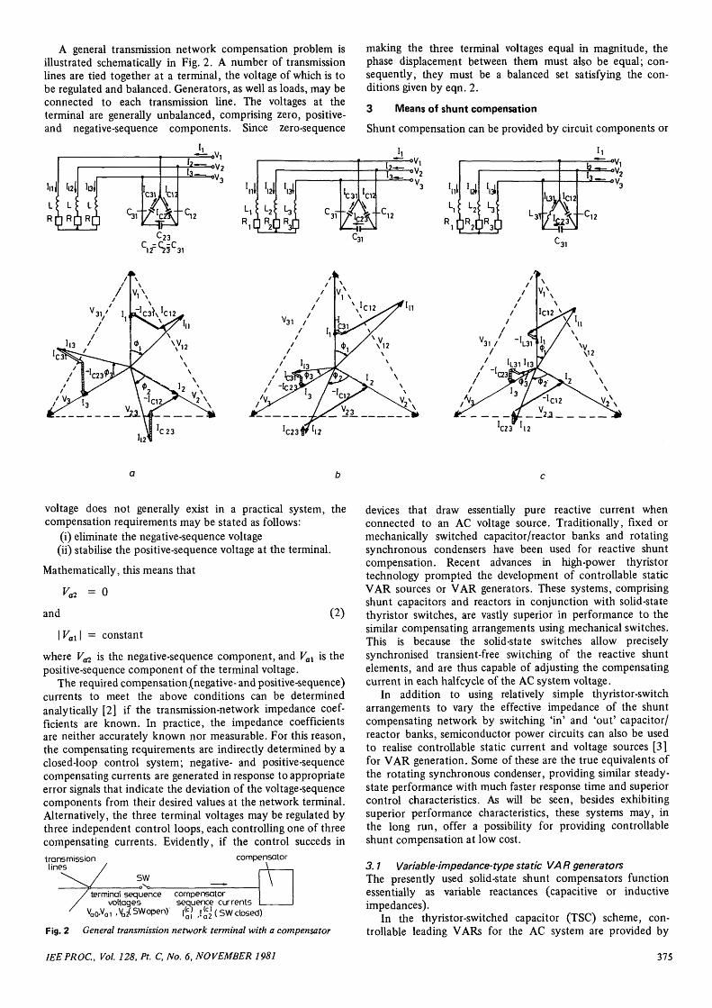
In a 3-phase system, the thyristor-switched capacitor banksare usually connected in delta as shown in Fig. 3. This arrange-
Fig. 3 Static VAR generator scheme using thyristor-switched capaci-tor banks
ment is particularly advantageous when unbalanced powerconsumption is anticipated. In practice, it is necessary toconnect an appropriately dimensioned inductor in series witheach individual capacitor in order to limit possible surgecurrent in the thyristors and reduce the risk of establishingresonances with the (inductive) AC system impedance.
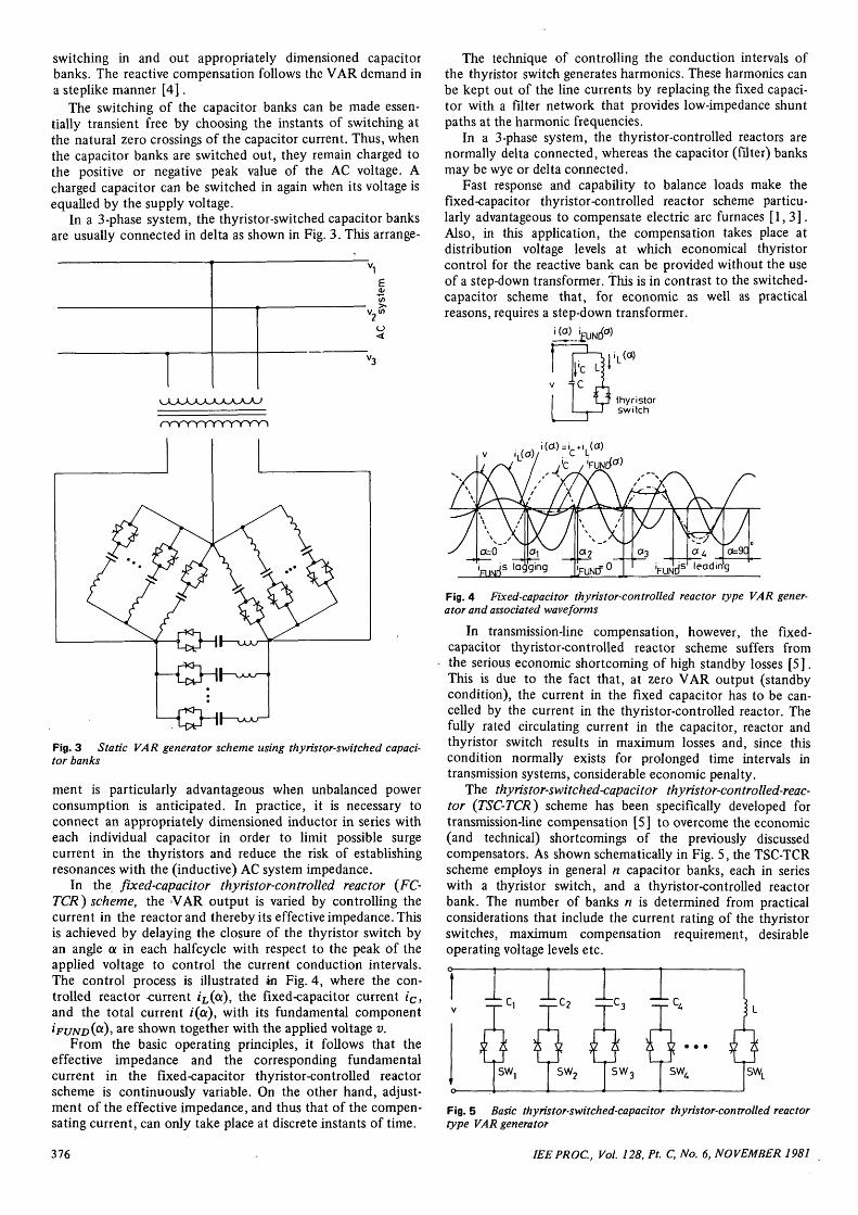
In the fixed-capacitor thyristor-controlled reactor (FC-TCR) scheme, the VAR output is varied by controlling thecurrent in the reactor and thereby its effective impedance. Thisis achieved by delaying the closure of the thyristor switch byan angle a in each halfcycle with respect to the peak of theapplied voltage to control the current conduction intervals.The control process is illustrated in Fig. 4, where the con-trolled reactor -current i£,(or), the fixed-capacitor current ic,and the total current i(oi), with its fundamental componentzVi/iVD(a)5 are shown together with the applied voltage v.
From the basic operating principles, it follows that theeffective impedance and the corresponding fundamentalcurrent in the fixed-capacitor thyristor-controlled reactorscheme is continuously variable. On the other hand, adjust-ment of the effective impedance, and thus that of the compen-sating current, can only take place at discrete instants of time.
The technique of controlling the conduction intervals ofthe thyristor switch generates harmonics. These harmonics canbe kept out of the line currents by replacing the fixed capaci-tor with a filter network that provides low-impedance shuntpaths at the harmonic frequencies.
In a 3-phase system, the thyristor-controlled reactors arenormally delta connected, whereas the capacitor (filter) banksmay be wye or delta connected.
Fast response and capability to balance loads make thefixed-capacitor thyristor-controlled reactor scheme particu-larly advantageous to compensate electric arc furnaces [1,3] .Also, in this application, the compensation takes place atdistribution voltage levels at which economical thyristorcontrol for the reactive bank can be provided without the useof a step-down transformer, this is in contrast to the switched-capacitor scheme that, for economic as well as practicalreasons, requires a step-down transformer.
i, (a)
thyristorswitch
Fig. 4 Fixed-capacitor thyristor-controlled reactor type VAR gener-ator and associated waveforms
In transmission-line compensation, however, the fixed-capacitor thyristor-controlled reactor scheme suffers fromthe serious economic shortcoming of high standby losses [5].This is due to the fact that, at zero VAR output (standbycondition), the current in the fixed capacitor has to be can-celled by the current in the thyristor-controlled reactor. Thefully rated circulating current in the capacitor, reactor andthyristor switch results in maximum losses and, since thiscondition normally exists for prolonged time intervals intransmission systems, considerable economic penalty.
The thyristor-switched-capacitor thyristor-controlled-reac-tor (TSC-TCR) scheme has been specifically developed fortransmission-line compensation [5] to overcome the economic(and technical) shortcomings of the previously discussedcompensators. As shown schematically in Fig. 5, the TSC-TCRscheme employs in general n capacitor banks, each in serieswith a thyristor switch, and a thyristor-controlled reactorbank. The number of banks n is determined from practicalconsiderations that include the current rating of the thyristorswitches, maximum compensation requirement, desirableoperating voltage levels etc.
l i. i I 1
Fig. 5 Basic thyristor-switched-capacitor thyristor-controlled reactortype VAR generator
376 IEEPROC, Vol. 128, Pt. C, No. 6, NOVEMBER 1981
VAR.
Fig. 6 Waveforms illustrating operation of the thyristor-switched-capacitor thyristor-controlled reactor type VAR generator
The basic operating principle of the TSC-TCR scheme is toapproximate the VAR demand with a positive difference(surplus) by switching in an appropriate number of capacitorbanks and, at the same time, to control the current in thereactor so as to cancel the surplus capacitive VARs. Thisoperating principle is illustrated for a TSC-TCR-type compen-sator employing four capacitor banks by the oscillogramsshown in Fig. 6.
The TSC-TCR scheme exhibits characteristics desirable fortransmission-line compensation: the VAR output is continu-ously variable both in the capacitive and inductive domains,the losses at (or below) zero VAR output are negligible, andthe capacitor and reactor banks can be independently switchedin and out during and following large system disturbances tominimise voltage transients [5].
3.2 Current-source-type VAR generatorsA simple current-source-type VAR generator can be realisedby an inductively loaded AC/DC convertor as shown inFig. 7. The convertor may be input-source (i.e. 'naturally')
- £ I S
i t
V
rr7Fig. 7 Current-source-type VAR generator employing an AC/DCconvertora Typical waveforms for providing lagging VARs with naturally commu-tated thyristorsb Typical waveforms for providing leading VARs with force-commu-tated thyristors
commutated or impulse (i.e. 'force') commutated. The nat-urally commutated convertor can only provide lagging VARs;by contrast, the force-commutated convertor can provide bothlagging and leading VARs. Typical current and voltage wave-forms illustrating the operation of the AC/DC convertor forlagging and leading VAR outputs are shown in Figs, la and b.
The AC/DC convertor is one of the simplest arrangementsto provide controllable 3-phase, VAR output. However, thepresently pratical naturally commutated version shows noadvantage over the variable impedance type schemes pre-viously discussed.
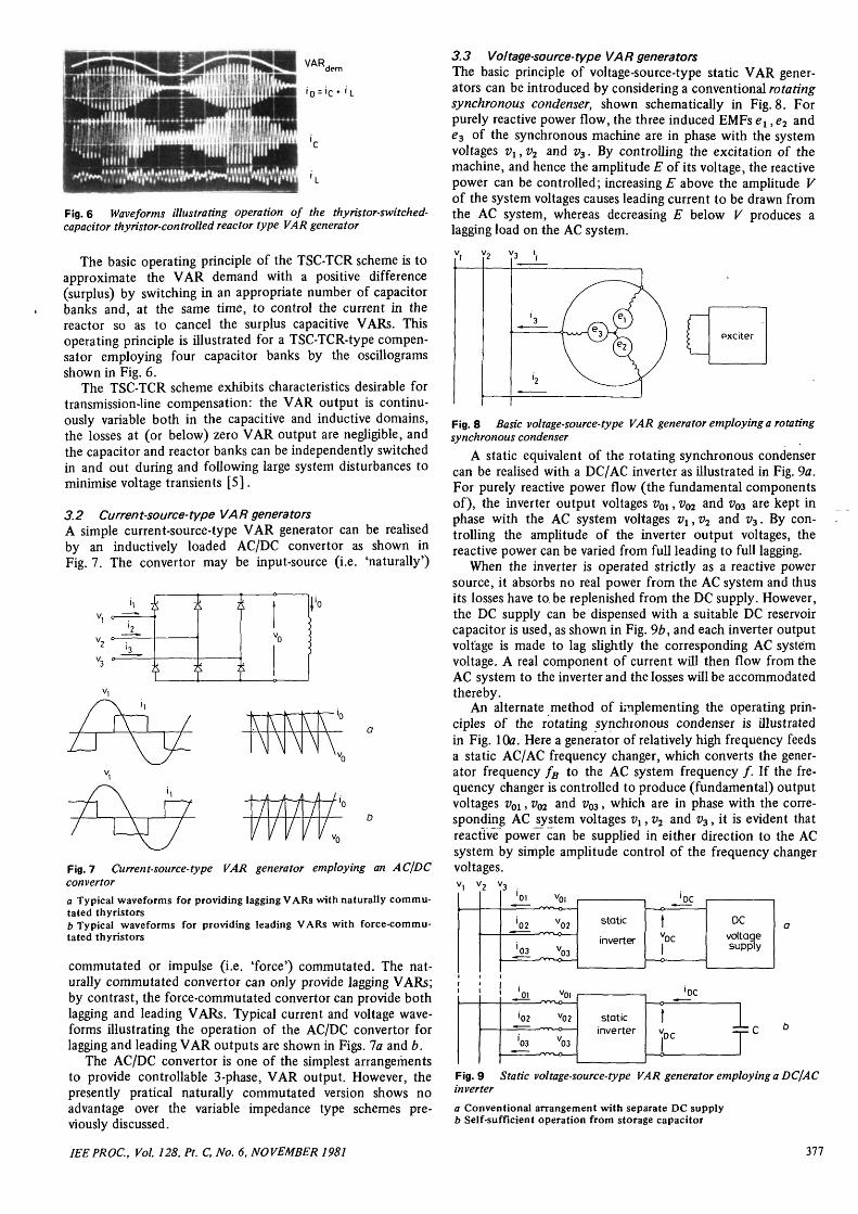
3.3 Voltage-source-type VAR generatorsThe basic principle of voltage-source-type static VAR gener-ators can be introduced by considering a conventional rotatingsynchronous condenser, shown schematically in Fig. 8. Forpurely reactive power flow, the three induced EMFs ex, e2 ande3 of the synchronous machine are in phase with the systemvoltages Vi, v2 and v3. By controlling the excitation of themachine, and hence the amplitude E of its voltage, the reactivepower can be controlled; increasing E above the amplitude Vof the system voltages causes leading current to be drawn fromthe AC system, whereas decreasing E below V produces alagging load on the AC system.
Fig. 8 Basic voltage-source-type VAR generator employing a rotatingsynchronous condenser
A static equivalent of the rotating synchronous condensercan be realised with a DC/AC inverter as illustrated in Fig. 9a.For purely reactive power flow (the fundamental componentsof), the inverter output voltages v01, zfo and vQ3 are kept inphase with the AC system voltages vt, v2 and v3. By con-trolling the amplitude of the inverter output voltages, thereactive power can be varied from full leading to full lagging.
When the inverter is operated strictly as a reactive powersource, it absorbs no real power from the AC system and thusits losses have to be replenished from the DC supply. However,the DC supply can be dispensed with a suitable DC reservoircapacitor is used, as shown in Fig. 9b, and each inverter outputvoltage is made to lag slightly the corresponding AC systemvoltage. A real component of current will then flow from theAC system to the inverter and the losses will be accommodatedthereby.
An alternate method of implementing the operating prin-ciples of the rotating synchronous condenser is illustratedin Fig. 10a. Here a generator of relatively high frequency feedsa static AC/AC frequency changer, which converts the gener-ator frequency fB to the AC system frequency / . If the fre-quency changer is controlled to produce (fundamental) outputvoltages vOi, vm and v03, which are in phase with the corre-sponding AC jjystem voltages vx, v2 and v3, it is evident thatreactive power can be supplied in either direction to the ACsystem by simple amplitude control of the frequency changervoltages.
static
inverter
'DC
VDC
DCvoltagesupply
staticinverter
'DC
"DCl cT
Fig. 9 Static voltage-source-type VAR generator employing a DC/ACinverter
a Conventional arrangement with separate DC supplyb Self-sufficient operation from storage capacitor
IEEPROC, Vol. 128, Pt. C, No. 6, NOVEMBER 1981 377
It might naturally be assumed that the reactive powerdrawn from the AC system is reflected through the frequencychanger to its input supply generator. Depending on the typeof frequency changer, this may or may not be true. A wellknown frequency changer, the phase-controlled cycloconverter,for example, draws lagging input current regardless of whetherthe output load is lagging or leading. Other types of frequencychangers [3] may invert the output-load phase angle at theinput, or may even supply a nonunity power factor load with aunity input power factor. Thus it follows that the high-fre-quency supply generator in Fig. 1 Ocr handles only reactiveand/or harmonic power. Therefore it can be replaced by amultiphase oscillating LC tank circuit as shown in Fig. 106. Aswith the scheme shown in Fig. 10fl, control of the reactivepower at the AC system side can be obtained through controlof the voltage generated at the output terminals of the fre-quency changer. The varying reactive load that may be reflectedto the tank circuit by the frequency changer, as the reactivepower at the AC side is varied, has the same effect as a variablereactance (inductance or capacitance, depending on the typeof frequency changer) connected in parallel with the LCcircuit; that is, it causes a variation in the natural operatingfrequency of the tank circuit. Since frequency changers canoperate from a variable frequency source, this frequencyvariation of the tank circuit, provided it is kept within reason-able limits by proper design, does not affect the operation ofthe system.
staticAC to AC
frequencychanger
'02
J03
high-frequencygenerator
staticAC to ACfrequencychanger
high-frequency'base'(oscillating tank circuit)
Fig. 10 Static voltage source type VAR generator employing AC'/ACfrequency changer
a Conventional arrangement with separate high-frequency AC source.b Self-sufficient operation from LC tank circuits (HF base)
In an actual system, it is, of course, necessary to replenishthe losses in the tank circuit to maintain the amplitude ofoscillation. This can be accomplished simply by introducingan appropriate phase shift between the output voltages of thefrequency changer and the AC system voltages.
The voltage-source-type VAR generators are theoreticallyexcellent solutions to the controllable shunt compensationproblems. They can provide continuously variable leading andlagging VARs, potentially without using large LC storagecomponents at the AC system frequency. They can be designedto produce negligible amount of harmonics and have anextremely fast response of VAR control. However, the inverter-type realisation requires semiconductor devices with intrinsicturnoff capability or forced commutation; both these pre-sently represent serious economic and other problems. Thefrequency-changer-type realisation can be implemented with anaturally commutated cycloconverter. However, the requiredLC circuit is relatively large, and, because of the relativelyhigh operating frequency (about 150—300 Hz), the corre-
sponding losses may represent an unacceptable economicpenalty. Turnoff-type devices or force commutation wouldallow the realisation of a 'unity input power factor frequencychanger' [3] that would allow a drastic reduction in the rating(and losses) of the LC tank circuit.
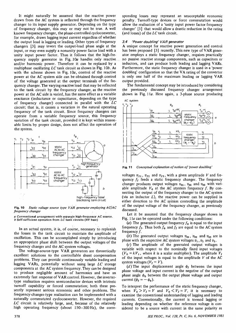
3.4 'Power doubling'VAR generatorA unique concept for reactive power generation and controlhas been proposed [3] recently. This new type of VAR gener-ator employs a static frequency changer, requires practicallyno passive. reactive storage components, such as capacitors orinductors, and can produce both leading and lagging VARs.Furthermore, the static frequency changer is used in a 'powerdoubling' configuration so that the VA rating of the convertoris only one half of the maximum leading or lagging VARoutput provided.
The fundamental concept may be introduced by consideringthe previously discussed frequency changer arrangementshown in Fig. 1 la. Here again, a 3-phase source producing
02
'01
102
k)3.j13.
'12..
iu
vi
V2
^3
L
L
L
kV,—o
kV2
kV3
staticfrequencychanger
v i——o
v 2
Fig. 11 Conceptual explanation of notion of 'power doubling'
voltages VJI , Vj2 and vI3, with a given amplitude V and fre-quency / 7 feeds a static frequency changer. The frequencychanger produces output voltages v01, vm and v03 with vari-able amplitude Vo at the AC stystem frequency / . By con-necting the output of the frequency changer to the AC system(via an inductor L), the reactive power can be supplied ineither direction to the AC system controlling the amplitudeof the output voltage of the frequency changer, as previouslydiscussed.
Let it be assumed that the frequency changer shown inFig. 1 la can be operated under the following conditions:
(a) The generated output frequency f0 is equal to the inputfrequency / / . Thus both f0 and fj are equal to the AC systemfrequency / .
(b) The generated output voltages v0l, vm and v03 are inphase with the respective AC system voltages vx, v2 and v3.
(c) The amplitude of the generated output voltages isvariable with respect to the nominally fixed input voltages(Vo =kVi, where fc is a scalar multiplier). The amplitude Vjof the input voltages is equal to the amplitude V of the ACsystem voltages (Vj= V).
(d)The input displacement angle 07 between the inputphase voltage and input current is the negative of the outputphase angle 0O between the output phase voltage and outputcurrent (0j = —0O).
To interpret the performance of the static frequency changer,when V0>Vj=V and V0<Vi= V, it is necessary toexamine the conventional understanding of lagging and leadingcurrents. Conventionally, the current is termed lagging orleading depending on whether the reference voltage is con-sidered to be a source with current in the same polarity as
378 IEEPROC, Vol. 128, Pt. C, No. 6, NOVEMBER 1981
the voltage, or a load with current in opposite polarity to thevoltage. For example, a simple capacitor viewed as a load drawsa current which leads its voltage. Viewed as a generator, thesame capacitor supplies a lagging current. Thus, if the staticfrequency changer output voltage Vo is greater than the ACsystem voltage V, then the current that flows is a leadingcurrent with respect to the AC system voltage. However, thefrequency changer observes at the output terminal the samecurrent to be lagging its generated output voltage. The con-verse is true when the frequency changer output voltage is lessthan V.
The frequency changer is defined as giving reverse polarityphase angle between its input and output currents. Thus, whenk is greater than unity (Ko > Vj = V), a leading current isdrawn from the AC system, and also from the frequencychanger input power source. Conversely, lagging current isdrawn from the AC system and the frequency changer inputpower source when k is less than unity (Ko < Vj — V). If A: isunity (Vo = Vj= V), the reactive current through the fre-quency changer is zero.
The above deductions lead directly to the essence of thepower doubling concept for reactive power generation. Sincethe voltages of the 3-phase source supplying the frequencychanger were stipulated to be perfect replicas of the ACsystem voltages (see conditions 2 and 3), it follows that theabove described current/voltage relationships will not change ifthe inputs of the frequency changer are removed from theexternal voltage source and connected to the AC system asshown in Fig. 116. Since both the input and output currentsof the frequency changer can simultaneously be made to leador lag the AC system voltages, the total reactive current drawnfrom the AC system will be the sum of these currents. If theinductance L is relatively small (as it would be in practice), theoutput and input currents will be approximately equal. Con-sequently, the VA rating of the static frequency changer isonly one half of the maximum leading or lagging outputsupplied.
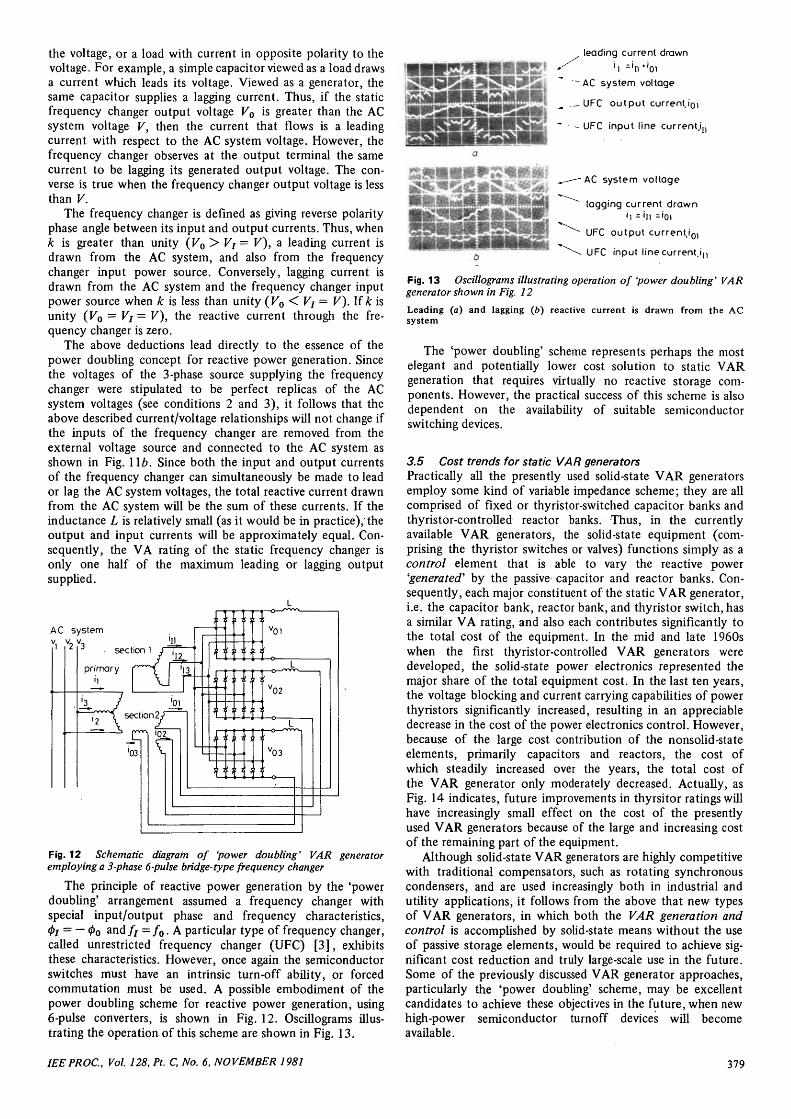
AC system
Fig. 12 Schematic diagram of 'power doubling' VAR generatoremploying a 3-phase 6-pulse bridge-type frequency changer
The principle of reactive power generation by the 'powerdoubling' arrangement assumed a frequency changer withspecial input/output phase and frequency characteristics,0/ = — 0o and// = / 0 . A particular type of frequency changer,called unrestricted frequency changer (UFC) [3], exhibitsthese characteristics. However, once again the semiconductorswitches must have an intrinsic turn-off ability, or forcedcommutation must be used. A possible embodiment of thepower doubling scheme for reactive power generation, using6-pulse converters, is shown in Fig. 12. Oscillograms illus-trating the operation of this scheme are shown in Fig. 13.
leading current drawn
~AC system voltage
._ UFC output current I'OI
~ - UFC input line current,!,,
AC system voltage
lagging current drawn'i = 'n ='oi
UFC output current,i0,
UFC input linecurrent.in
Fig. 13 Oscillograms illustrating operation of 'power doubling' VARgenerator shown in Fig. 12
Leading (a) and lagging (6) reactive current is drawn from the ACsystem
The 'power doubling' scheme represents perhaps the mostelegant and potentially lower cost solution to static VARgeneration that requires virtually no reactive storage com-ponents. However, the practical success of this scheme is alsodependent on the availability of suitable semiconductorswitching devices.
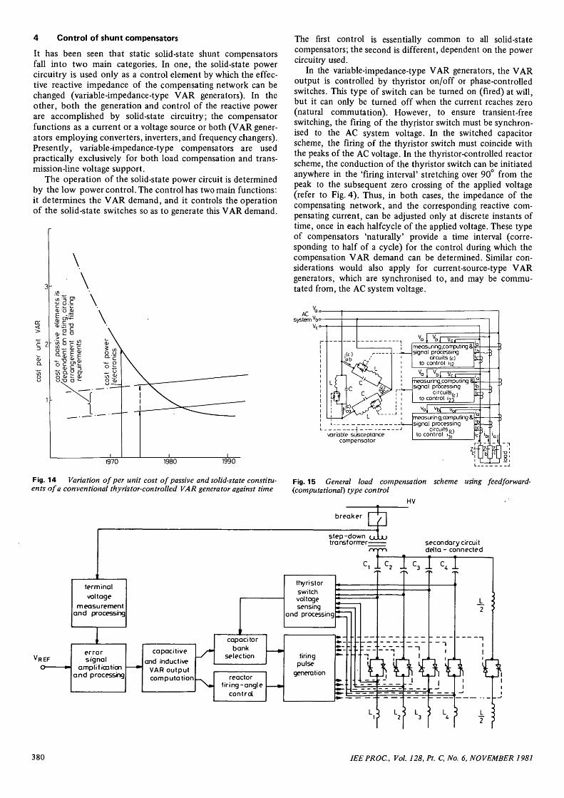
3.5 Cost trends for static VAR generatorsPractically all the presently used solid-state VAR generatorsemploy some kind of variable impedance scheme; they are allcomprised of fixed or thyristor-switched capacitor banks andthyristor-controlled reactor banks. Thus, in the currentlyavailable VAR generators, the solid-state equipment (com-prising the thyristor switches or valves) functions simply as acontrol element that is able to vary the reactive power'generated' by the passive capacitor and reactor banks. Con-sequently, each major constituent of the static VAR generator,i.e. the capacitor bank, reactor bank, and thyristor switch, hasa similar VA rating, and also each contributes significantly tothe total cost of the equipment. In the mid and late 1960swhen the first thyristor-controlled VAR generators weredeveloped, the solid-state power electronics represented themajor share of the total equipment cost. In the last ten years,the voltage blocking and current carrying capabilities of powerthyristors significantly increased, resulting in an appreciabledecrease in the cost of the power electronics control. However,because of the large cost contribution of the nonsolid-stateelements, primarily capacitors and reactors, the cost ofwhich steadily increased over the years, the total cost ofthe VAR generator only moderately decreased. Actually, asFig. 14 indicates, future improvements in thyrsitor ratings willhave increasingly small effect on the cost of the presentlyused VAR generators because of the large and increasing costof the remaining part of the equipment.
Although solid-state VAR generators are highly competitivewith traditional compensators, such as rotating synchronouscondensers, and are used increasingly both in industrial andutility applications, it follows from the above that new typesof VAR generators, in which both the VAR generation andcontrol is accomplished by solid-state means without the useof passive storage elements, would be required to achieve sig-nificant cost reduction and truly large-scale use in the future.Some of the previously discussed VAR generator approaches,particularly the 'power doubling' scheme, may be excellentcandidates to achieve these objectives in the future, when newhigh-power semiconductor turnoff devices will becomeavailable.
IEEPROC, Vol. 128, Pt. C, No. 6, NOVEMBER 1981 379
4 Control of shunt compensators
It has been seen that static solid-state shunt compensatorsfall into two main categories. In one, the solid-state powercircuitry is used only as a control element by which the effec-tive reactive impedance of the compensating network can bechanged (variable-impedance-type VAR generators). In theother, both the generation and control of the reactive powerare accomplished by solid-state circuitry; the compensatorfunctions as a current or a voltage source or both (VAR gener-ators employing converters, inverters, and frequency changers).Presently, variable-impedance-type compensators are usedpractically exclusively for both load compensation and trans-mission-line voltage support.
The operation of the solid-state power circuit is determinedby the low power control. The control has two main functions:it determines the VAR demand, and it controls the operationof the solid-state switches so as to generate this VAR demand.
1970 1980 1990
Fig. 14 Variation of per unit cost of passive and solid-state constitu-ents of a conventional thyristor-controlled VAR generator against time
The first control is essentially common to all solid-statecompensators; the second is different, dependent on the powercircuitry used.
In the variable-impedance-type VAR generators, the VARoutput is controlled by thyristor on/off or phase-controlledswitches. This type of switch can be turned on (fired) at will,but it can only be turned off when the current reaches zero(natural commutation). However, to ensure transient-freeswitching, the firing of the thyristor switch must be synchron-ised to the AC system voltage. In the switched capacitorscheme, the firing of the thyristor switch must coincide withthe peaks of the AC voltage. In the thyristor-controlled reactorscheme, the conduction of the thyristor switch can be initiatedanywhere in the 'firing interval' stretching over 90° from thepeak to the subsequent zero crossing of the applied voltage(refer to Fig. 4). Thus, in both cases, the impedance of thecompensating network, and the corresponding reactive com-pensating current, can be adjusted only at discrete instants oftime, once in each halfcycle of the applied voltage. These typeof compensators 'naturally' provide a time interval (corre-sponding to half of a cycle) for the control during which thecompensation VAR demand can be determined. Similar con-siderations would also apply for current-source-type VARgenerators, which are synchronised to, and may be commu-tated from, the AC system voltage.
system
variable susceptancecompensator
measuring, com put ing &signal processing
circuits /r)to control \^' .y_ai
Fig. 15 General load compensation scheme using feedforward-(computational) type control
HV
breaker
step-downtransformer secondary circuit
delta - connected
terminalvoltage
measurementand processing
VREFerrorsignal
amplificationand processing
capacitiveand inductive
VAR outputcomputation
capacitorbank
selection
reactorfiring-angle
control
thyristorswitchvoltagesensing
and processing
firingpulse
generation
380 IEEPROC, Vol. 128, Pt. C, No. 6, NOVEMBER 1981
Voltage-source-type VAR generators employing a solid-state convertor would generally have an internal switchingpattern and rate which are not directly related to the ACsystem voltages. These VAR generators could be controlled bya 'reference wave' which is proportional to the amplitude andphase of the generated output voltage (having the frequency ofthe AC system). In this case, the VAR output is controlledsimply by adjusting the amplitude of the reference wave. Thisarrangement thus provides a VAR output control that is similarto that of a conventional rotating synchronous machine (ofcourse, with much smaller time constant).
Three basic approaches are generally used to control staticVAR generators. The first is a direct computational, so called'feedforward', method which repeatedly solves a set ofappropriate steady-state equations characterising the networkand VAR generator to find the currents required for compen-sation. The second is a feedback control method, in which thecompensator is closed-loop controlled so as to reduce certainerror signals. The third approach may be termed hybrid; it usesa combination of the feedforward and feedback techniques.The first approach is normally only suitable to control loadcompensators. The second one is usually used to control com-pensators regulating terminal voltage. The third approach maybe used to control compensators in either applications.
All feedforward (computational-type) control approachesare based on the fundamental presumption that the load (andthe AC system) is in steady state between any two consecutiveinstants of time at which the current in the compensator ischanged. Thus, between these time instants, the relevant loadcurrents (or power, or impedances) can be measured and, fromthese, the required compensating current can be determinedusing appropriate steady-state equations [2]. The feedforwardapproach can naturally control the three compensating currentsindependently of each other. A typical compensator employingthyristor-controlled reactors with feedforward control isshown in Fig. 15.
Feedback control techniques are generally used to support(regulate) transmission-line terminal voltage [6]. (They couldalso be used for load compensation if the response timerequirements were moderate.) The static VAR generator ismade to respond to an appropriate error signal. The errorsignal represents the difference between a chosen referenceand a corresponding parametric value of the variable to becontrolled. Any change in the error signal results in an opposingchange in the VAR generator output current. This tends tokeep the error constant and close to zero. A typical closed-loop control arrangement for a switched-capacitor thyristor-controlled reactor type transmission line compensator isshown in Fig. 16.
5 Summary
Functionally, static shunt compensators can be divided intotwo classes: those which compensate for specific load disturb-ances and those which regulate (support) transmission-lineterminal voltage. The general objectives of the first class aredynamic load balancing and power factor correction; those ofthe second class are terminal voltage balancing and regulation.
Static shunt compensators function as variable reactances(capacitive or inductive impedances) or controllable currentand voltage sources. The variable impedance approachemploying high-power thyristor switches to control current inreactive circuit elements is gaining widespread acceptance bothin industrial and utility applications. Other approaches,employing semiconductor switches with turnoff ability, cangenerate controllable reactive power without the use of passivestorage elements (capacitors and inductors). These offer thepotential for significant cost reduction and performanceimprovement in future when high-power gate turnoff deviceswill become available.
There are three basic approaches to the control of staticshunt compensators. The first is a direct computational ('feed-forward') approach in which a set of equations defining thecompensating currents in terms of load and/or AC systemparameters are solved at regular time intervals. The second is afeedback control approach in which the compensating currentsare closed-loop controlled to maintain some parametric valuesof variables of interest at desired levels. The third approachuses a combination of feedforward and feedback techniques.Feedforward controls are fast and inherently stable. They areoften used in load (arc furnace) compensators. Feedbackcontrols are accurate and tolerant of changes in the controlelements and the system controlled. They are usually used intransmission-line compensators.
6 References
1 GYUGYI, L., and OTTO, R.A.: 'Static compensation for voltageflicker reduction and power factor correction'. Proceedings of theAmerican Power Conference, 1976
2 GYUGYI, L., OTTO, R.A., and PUTMAN, T.H.: 'Principles andapplications of static, thyristor-controlled shunt compensator',IEEE Trans., 1978, PAS-97, pp. 1935-1945
3 GYUGYI, L.: 'Reactive power generation and control by thyristorcircuits', ibid., 1979, IA-15, pp. 521-532
4 FRANK, H., and LANDSTORM, B.: 'Power factor correction withthyristor-controlled capacitors', ASEAJl, 1974, 44, pp. 180-184
5 GYUGYI, L., and TAYLOR, E.R.: 'Characteristics of static,thyristor-controlled shunt compensators for power transmissionsystem applications', IEEE Trans., 1980, PAS-99, pp. 1329-1338
6 SCHWEIKARDT, H.W., ROMEGIALI, G., and REICHERT, K.:'Closed loop control of static VAR sources (SVC) on EHV trans-mission lines', Papaer A78 135-6 presented at IEEE PES 1978Winter Power Meeting
IEEPROC, Vol. 128, Pt. C, No. 6, NOVEMBER 1981 381