REALIZATION OF TRANSVERSE FEEDBACK SYSTEM FOR SIS18/100 USING FPGA T. Rückelt, M. Alhumaidi and A.M. Zoubir, TU Darmstadt, Darmstadt, Germany Abstract Higher beam intensities in particle accelerator are usually prevented by beam instabilities. To cure these instabilities, additional active systems must be used besides passive damping. For this purpose, we have developed a distributed low-latency Transverse Feedback System (TFS) using Field Programmable Gate Arrays (FPGA). Data acquisition takes place on multiple Beam Position Monitors (BPM) with individual FPGAs and ADCs around the accelerator ring. Acquired data is compressed, and sent over broadband fiber optic wires to a central unit (CU). For synchronization, data is tagged using timestamps from a reference time, which is distributed by a specially constrained network time protocol to obtain cycle accuracy. The CU provides a FIR filter for system bandwidth limitation, and an adaptive IIR filter for stable beam signal rejection. Feedback is given using a linear combination of the pre-processed BPM signals. The system provides substantial flexibility, due to the possibility to configure most parameters online. Filters, feedback sources and parameters, compression rate, and more can be adapted via an Ethernet interface, which also supplies analysis data. Results are shown. INTRODUCTION A Transverse Feedback System (TFS) applies a phase shifted Beam Position Monitor (BPM) signal to the particle beam using the kicker to damp betatron oscillation. For proper damping, the signal has to be delayed to reach a phase advance of π/2.Using two or more BPM signals, each desired phase can be reconstructed using a linear combination. In our work, a TFS has been developed that matches requirements of SIS18 and SIS100 at GSI due to substantial configurability. We focused on the digital subsystem of the TFS introduced in [1]. It includes position data acquisition from multiple devices, signal filtering and feedback calculation. With a higher BPM count, a better signal to noise ratio (SNR) can be achieved, as proposed in[2]. Hereby, we introduce the use of a distributed system which provides better system flexibility. In comparison to other systems [3][4], no dedicated BPMs have to be available for TFS and signal quality can be enhanced by the use of multiple sensors. As drawback, it is more complex because the additional tasks of communication and synchronization have to be maintained. The difficulties and our solutions are explained. For data acquisition, multiple Libera Hadron devices which are already used for beam diagnostics have been deployed to which the BPMs are attached. In our concept, a number of these Libera devices form a so called cluster. Each cluster is connected to the Central Unit (CU) FPGA using a dedicated fiber optic line to send compressed position data. This line introduces timing uncertainty to the system which has to be eliminated to allow proper operation. Therefore, we have developed a special synchronization concept which is explained in detail. The CU has filters for system bandwidth limitation and stable beam signal rejection available. The adaptive delay which is needed for the phase shift is incorporated into the synchronization concept. Synchronized BPM signals are finally used to calculate the feedback signal. The general structure of the distributed system is shown in Figure 1. Figure 1: General structure of the distributed TFS. In the first part of the paper, the new concept for data acquisition using a distributed system is addressed. Subsystems have to be well synchronized in order to be able to operate properly. Therefore, the developed synchronization concept is introduced in the second part. Data processing of acquired position data is performed by the CU which is explained in the third part. Finally, results are evaluated and a conclusion is given. DATA ACQUISITION CONCEPT For data acquisition we define so called clusters of Libera devices. Devices in a cluster are interconnected by high speed communication links in star topology. The center device of a star is denoted as cluster master. It is connected to the CU via optical fiber multi-gigabit link. However, the bandwidth of this link has to be shared among the members of the cluster. MOPC29 Proceedings of IBIC2013, Oxford, UK ISBN 978-3-95450-127-4 Copyright c ○ 2013 by JACoW — cc Creative Commons Attribution 3.0 (CC-BY-3.0) 128 BPMs and Beam Stability
Transcript
REALIZATION OF TRANSVERSE FEEDBACK SYSTEM FOR SIS18/100 USING FPGA
T. Rückelt, M. Alhumaidi and A.M. Zoubir, TU Darmstadt, Darmstadt, Germany
Abstract Higher beam intensities in particle accelerator are
usually prevented by beam instabilities. To cure these instabilities, additional active systems must be used besides passive damping. For this purpose, we have developed a distributed low-latency Transverse Feedback System (TFS) using Field Programmable Gate Arrays (FPGA). Data acquisition takes place on multiple Beam Position Monitors (BPM) with individual FPGAs and ADCs around the accelerator ring. Acquired data is compressed, and sent over broadband fiber optic wires to a central unit (CU). For synchronization, data is tagged using timestamps from a reference time, which is distributed by a specially constrained network time protocol to obtain cycle accuracy. The CU provides a FIR filter for system bandwidth limitation, and an adaptive IIR filter for stable beam signal rejection. Feedback is given using a linear combination of the pre-processed BPM signals. The system provides substantial flexibility, due to the possibility to configure most parameters online. Filters, feedback sources and parameters, compression rate, and more can be adapted via an Ethernet interface, which also supplies analysis data. Results are shown.
INTRODUCTION A Transverse Feedback System (TFS) applies a phase
shifted Beam Position Monitor (BPM) signal to the particle beam using the kicker to damp betatron oscillation. For proper damping, the signal has to be delayed to reach a phase advance of π/2.Using two or more BPM signals, each desired phase can be reconstructed using a linear combination. In our work, a TFS has been developed that matches requirements of SIS18 and SIS100 at GSI due to substantial configurability.
We focused on the digital subsystem of the TFS introduced in [1]. It includes position data acquisition from multiple devices, signal filtering and feedback calculation. With a higher BPM count, a better signal to noise ratio (SNR) can be achieved, as proposed in[2].
Hereby, we introduce the use of a distributed system which provides better system flexibility. In comparison to other systems [3][4], no dedicated BPMs have to be available for TFS and signal quality can be enhanced by the use of multiple sensors. As drawback, it is more complex because the additional tasks of communication and synchronization have to be maintained. The difficulties and our solutions are explained.
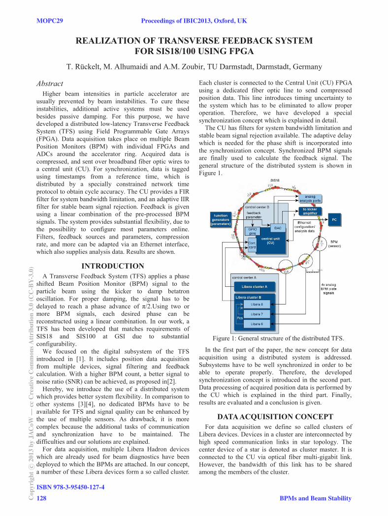
For data acquisition, multiple Libera Hadron devices which are already used for beam diagnostics have been deployed to which the BPMs are attached. In our concept, a number of these Libera devices form a so called cluster.
Each cluster is connected to the Central Unit (CU) FPGA using a dedicated fiber optic line to send compressed position data. This line introduces timing uncertainty to the system which has to be eliminated to allow proper operation. Therefore, we have developed a special synchronization concept which is explained in detail.
The CU has filters for system bandwidth limitation and stable beam signal rejection available. The adaptive delay which is needed for the phase shift is incorporated into the synchronization concept. Synchronized BPM signals are finally used to calculate the feedback signal. The general structure of the distributed system is shown in Figure 1.
Figure 1: General structure of the distributed TFS.
In the first part of the paper, the new concept for data acquisition using a distributed system is addressed. Subsystems have to be well synchronized in order to be able to operate properly. Therefore, the developed synchronization concept is introduced in the second part. Data processing of acquired position data is performed by the CU which is explained in the third part. Finally, results are evaluated and a conclusion is given.
DATA ACQUISITION CONCEPT For data acquisition we define so called clusters of
Libera devices. Devices in a cluster are interconnected by high speed communication links in star topology. The center device of a star is denoted as cluster master. It is connected to the CU via optical fiber multi-gigabit link. However, the bandwidth of this link has to be shared among the members of the cluster.
MOPC29 Proceedings of IBIC2013, Oxford, UK
ISBN 978-3-95450-127-4
Cop
yrig
htc ○
2013
byJA
CoW
—cc
Cre
ativ
eC
omm
onsA
ttri
butio
n3.
0(C
C-B
Y-3.
0)
128 BPMs and Beam Stability
This architecture allows to add multiple data sources to the TFS using only a single fiber optic line per cluster. Delta signals of BPMs which contain position information data are determined and compressed locally to match the bandwidth of the shared communication channel. For compression, a down sampling of the low pass filtered delta signal is applied. Its rate can be adapted by the user via Ethernet and has to be matched to the bandwidth of the common link. However, high compression reduces signal bandwidth and quality. At excessive compression, the system loses its property to address higher order modes. The user has to find a trade-off.
For high speed communication, we selected Xilinx Aurora protocol which provides robust low-latency and high-speed link layer connectivity between two points. It is stable and only few nanoseconds slower than hand optimized stacks as shown in [5]. On top, we implemented a 16 Bit checksum error detection mechanism to enhance data integrity.
SYNCHRONIZATION OF SUBSYSTEMS The TFS requires an exact timing behaviour to be able
to perform precise phase shifts using signal delay. However, the distributed system uses a communication
channel which introduces timing uncertainty. To overcome this uncertainty, a synchronization concept is introduced. The most important part of the synchronization concept is our developed Time Update Protocol (TUP) that is a constrained derivate of the commonly used Network Time Protocol (NTP). The protocol synchronizes two independent time counters at distinct devices.
In NTP, a time slave sends a request to a time master and stores the time of sending to t1. The time master registers the arrival of the request and stores the point in time to t2. It sends a response at time t3 which includes t2 and t3. At arrival of the response, the slave registers time t4.
The slave is then able to determine the time of the master using the round-trip-time (RTT) of(1), according to [6]. (1)
TUP Synchronization Protocol The channel established by Aurora link has turned out
to have a slowly changing latency due to incorporated clock phase alignment strategy. Within a short period of time, the latency can be regarded to be constant and equal for both directions of the channel. We developed TUP which we implemented in hardware logic. Therefore, the response can be ensured to be sent immediately such that
. This way, the overall time for one synchronization sequence can be minimized and the delay of both directions of the channels are nearly equal. The equation of TUP RTT is reduced to (2). The messaging sequence is depicted in Figure 2. (2)
To be able to send the message immediately, two constraints have to be met.
Dynamic data buffers of the communication stack have to be empty to eliminate indeterministic buffer delays
The communication module has to be ready to send
Figure 2: TUP Synchronization Sequence.
Our light-weight TUP implementation is integrated deep into the extended communication stack so that this information is available to TUP but hidden from upper layers at the same time. According to our synchronization logic, TUP slave modules delay their time request (TR) message until both constraints are fulfilled. The master suppresses the response time update (TU) message instead if constraints do not hold on arrival of TR and waits for another TR while blocking the channel.
Using TUP synchronization scheme, local counters can be synchronized to cycle accuracy which represents an optimal synchronization. We use these synchronized counters to recover the timing of data streams that use an uncertain channel. Therefore, data is tagged by synchronized counter timestamps before entering the uncertain time domain during transfer. Attached timestamps are used at the CU to realign data streams according to their original timing. This way, timing accuracy is reduced to the accuracy of the TUP protocol.
Figure 3: TUP Structure.
ARCHITECTURE OF THE CU The developed design for the Central Unit contains a
logic main module for TFS functionality which is attached indirectly to interface modules including the Aurora connection, Ethernet UDP Stack for system control and a DAC for feedback output. These modules abstract interfaces to simplify system integration. However, the architecture of the TFS module itself is most interesting and therefore addressed more in detail in the following. Its structure is shown in Figure 4.
Proceedings of IBIC2013, Oxford, UK MOPC29
BPMs and Beam Stability
ISBN 978-3-95450-127-4
129 Cop
yrig
htc ○
2013
byJA
CoW
—cc
Cre
ativ
eC
omm
onsA
ttri
butio
n3.
0(C
C-B
Y-3.
0)
Figure 4: Structure of the TFS Module.
TFS Module The TFS Module contains our developed Aurora Core
which implements the interface for incoming position data from Libera devices. Our Core integrates Xilinx Aurora module, enhanced error detection and the TUP Module for time counter synchronization as well as features for further analysis and channel verification.
It passes data to a Frame Unpacker which decodes frames containing data, time tags, source IDs and other parameters. The decoded streams contain data of the whole cluster. Moreover, it is required to perform further calculation on data of a single BPM. Therefore, a developed source splitter is introduced, which splits streams from a cluster according to the source IDs of individual data frames.
The pipeline consisting of these three modules exists for each attached cluster. It maps merged streams of individual Libera devices on distinct data paths. These distinct paths are called slots in the following.
Data streams in slots are passed to separate instances of our developed Preprocessing Unit which implements data decompression and signal filtering.
Decompression is accomplished by linear interpolation of the down sampled signal and recovers the original sampling rate of the stream. This is an important issue for subsequent signal filtering.
Signal bandwidth of acquired data streams is reduced using a 32 tap FIR low pass filter. The size and coefficients of this filter can be adapted by the user during operation.
A notch filter to suppress DC offset and revolution harmonics is inserted as next part of the pipeline. It uses an IIR filter and adaptive down sampling to match the revolution harmonics, like proposed in [7].This down sampling is performed by taking every nth sample into account, according to the IIR transfer function of order k in (3).
(3)
This down sampling strategy is realized by the use of dual port RAM blocks which allow directed access to specific samples. Furthermore, it is implemented as contrary filter whose results are subtracted from current filter inputs. This procedure reduces filter latency and is
applicable because the suppressed offset changes very slowly. Like the FIR filter, its coefficients can be changed during operation by the user. Its order k is set to 3.
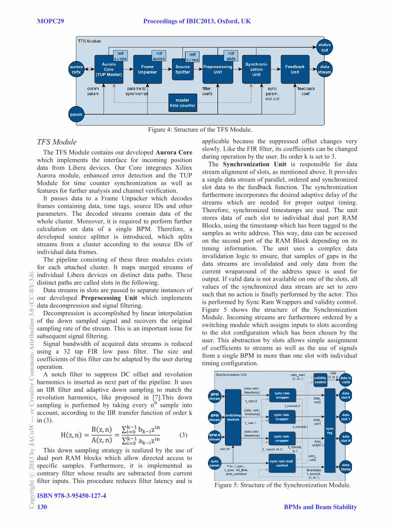
The Synchronization Unit is responsible for data stream alignment of slots, as mentioned above. It provides a single data stream of parallel, ordered and synchronized slot data to the feedback function. The synchronization furthermore incorporates the desired adaptive delay of the streams which are needed for proper output timing. Therefore, synchronized timestamps are used. The unit stores data of each slot to individual dual port RAM Blocks, using the timestamp which has been tagged to the samples as write address. This way, data can be accessed on the second port of the RAM Block depending on its timing information. The unit uses a complex data invalidation logic to ensure, that samples of gaps in the data streams are invalidated and only data from the current wraparound of the address space is used for output. If valid data is not available on one of the slots, all values of the synchronized data stream are set to zero such that no action is finally performed by the actor. This is performed by Sync Ram Wrappers and validity control. Figure 5 shows the structure of the Synchronization Module. Incoming streams are furthermore ordered by a switching module which assigns inputs to slots according to the slot configuration which has been chosen by the user. This abstraction by slots allows simple assignment of coefficients to streams as well as the use of signals from a single BPM in more than one slot with individual timing configuration.
Figure 5: Structure of the Synchronization Module.
MOPC29 Proceedings of IBIC2013, Oxford, UK
ISBN 978-3-95450-127-4
Cop
yrig
htc ○
2013
byJA
CoW
—cc
Cre
ativ
eC
omm
onsA
ttri
butio
n3.
0(C
C-B
Y-3.
0)
130 BPMs and Beam Stability
EVALUATION The most critical parts of the design are timing based.
To attend timing issues between devices of the distributed system, the TUP synchronization has been developed. Furthermore, low latency is required for the system because high latencies lead to inaccuracies in feedback signal determination. To allow better benchmarking of the final system, it is required to be very flexible. Moreover it has to fit for SIS18 and SIS100.
TUP Timer Synchronization TUP synchronization protocol has been simulated
extensively using Xilinx ISim Simulator under variation of channel characteristics, individual device clocks and under different amount of channel load. The protocol has always performed as desired.
First tests on FPGA have shown, that device synchronization using TUP works very efficient and accurate. Inaccuracies in each direction have been up to one cycle which is optimal. Tests could not yet be performed with the final hardware of 200 meters long fiber optic cables but only with a 5 meter copper cable. Nevertheless, results using the final hardware are expected to be similar because optical line characteristics are free of electromagnetic interferences. Inaccuracies will only be caused by hardware which has also been part of the first tests, except the optical transceiver modules.
Latency The latency of the complete TFS at SIS18 is expected
to be about 4.25 μs from signal measurement to the kicker action. The digital parts of the system which have been developed have been optimized for latency and create only one third of the total delay, as illustrated in Figure 6.
Especially latencies of the developed logic hardware at the Libera device and Central Unit are very low with 0.34 μs (8%) and 0.56μs (13%), respectively. The communication stack for Xilinx Aurora protocol and error detection needs additionally about 0.69 μs of time (16%).
Figure 6: Latency share.
Analog delays at SIS18 are caused by signal traveling times from BPMs to the Libera devices, to the Central Unit and finally to the exciter. Because they are located in different control rooms as shown in Figure 1, long paths of about 530 meters in total have to be taken into account. This distance is split on 250 meters from farthest BPM to Libera devices, 200 meters from Libera devices to the CU and 80 meters from the CU to the kicker.
With a signal speed of about 2/3 speed of light, the analog latency of wires is about 2.65 μs.
It is recommended to locate used Libera devices near the CU so that the total cable distance can be reduced to 200 meters in total and latency decreases to 1 μs. Total latency can therefore be reduced by 38.9% to 2.59 μs.
Flexibility The realization of the system in a distributed manner
and the concept of clustering make data acquisition very flexible. Further signal sources can be attached with plug and play. BPMs can be selected for feedback during operation using the Ethernet user interface and a developed software tool. Important parameters which influence synchronization and signal filtering can also be adapted during operation. This allows complex bench-marking and fast optimization the TFS with few effort.
CONCLUSION AND FUTURE WORK The elaborated concept and the implemented part of the
digital TFS represent an important milestone in the development of the TFS for SIS100. In this paper an overall system concept using a novel distributed data acquisition strategy for TFS has been elaborated. It uses multiple sensors for feedback determination and allows easy system extension by plug&play. Substantial system parameters can be varied via Ethernet user interface. The system is characterized by substantial flexibility and quite low latency.
The synchronization of the subsystems is reliably maintained by the developed light-weight Time Update Protocol (TUP) which reaches cycle accuracy and is therefore optimal for time counter synchronization.
The current implementation does not cover the complete concept yet. Online input of feedback coefficient and preamplifier gain as well as features of the user interface are missing. Moreover, the current system still has to be tested more in detail to verify the filters and feedback operation.
REFERENCES [1] U. Blell et al. ”Transverse Damping System at SIS100”,
Proceedings of EPAC 2006, Edinburgh, Scotland [2] M. Aluhmaidi et al., “A Transverse Feedback System using
multiple Pickups for Noise Minimization” IPAC’11 [3] E.V. Gorbachev et al., “Implementing Elements of Digital
Transverse Feedback System in Altera FPGA”, Proceedings of the RuPAC 2008
[4] M. Lonza et al., “Digital Processing Electronics for the ELETTRA Transverse Multi-Bunch Feedback System”, International Conference of Accelerator and Large Experimental Physics Control Systems, 1999, Trieste, Italy
[5] D. Makowski et al., “Low Latency Data Transmission in LLRF Systems” Proceedings of Particle Accelerator Conference 2011, New York, USA
[6] A. Tanenbaum et al., Distributed Systems: Principles and paradigms (Prentice Hall 2006), Chapter 6
[7] V. Rossi, “Digital Signal Processing Applications and Implementation for Accelerators”, Workshop on DSP Applications CERN-SL, 2002, Geneva, Switzerland