88
RF-TE, #2: Wireless transmitter and receiver architectures 6 ©Jvdtang Receiver architectures
RF-TE, #2: Wireless transmitter and receiver architectures 6©Jvdtang
Receiver architectures
RF-TE, #2: Wireless transmitter and receiver architectures 7©Jvdtang
Introduction
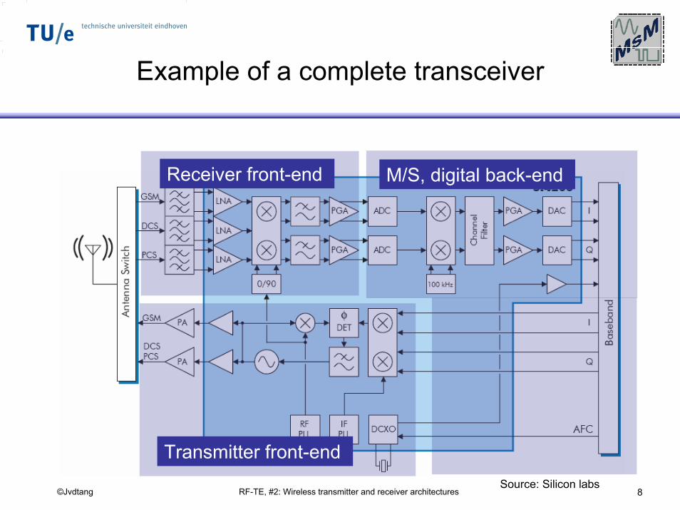
RF-TE, #2: Wireless transmitter and receiver architectures 8©Jvdtang
Example of a complete transceiver
Source: Silicon labs
Receiver front-end
Transmitter front-end
M/S, digital back-end
RF-TE, #2: Wireless transmitter and receiver architectures 9©Jvdtang
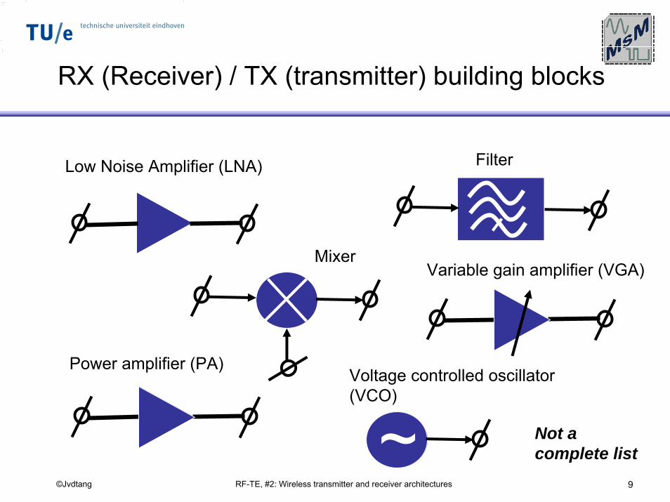
RX (Receiver) / TX (transmitter) building blocks
FilterLow Noise Amplifier (LNA)
MixerVariable gain amplifier (VGA)
Power amplifier (PA)Voltage controlled oscillator (VCO)
~ Not a complete list
RF-TE, #2: Wireless transmitter and receiver architectures 10©Jvdtang
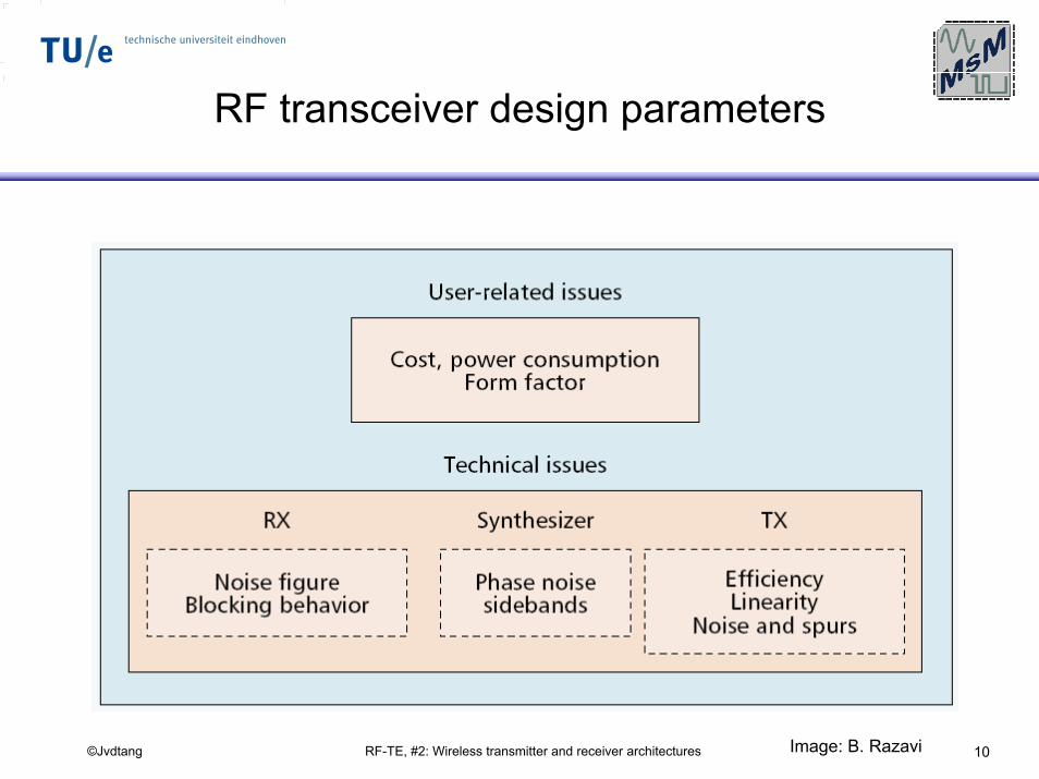
RF transceiver design parameters
Image: B. Razavi
RF-TE, #2: Wireless transmitter and receiver architectures 11©Jvdtang
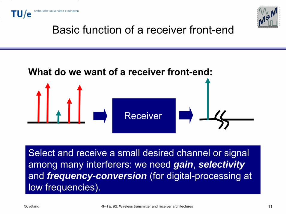
Basic function of a receiver front-end
What do we want of a receiver front-end:
Receiver
Select and receive a small desired channel or signal among many interferers: we need gain, selectivityand frequency-conversion (for digital-processing at low frequencies).
RF-TE, #2: Wireless transmitter and receiver architectures 12©Jvdtang
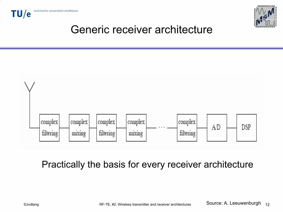
Generic receiver architecture
Practically the basis for every receiver architecture
Source: A. Leeuwenburgh
RF-TE, #2: Wireless transmitter and receiver architectures 13©Jvdtang
General RX aspects
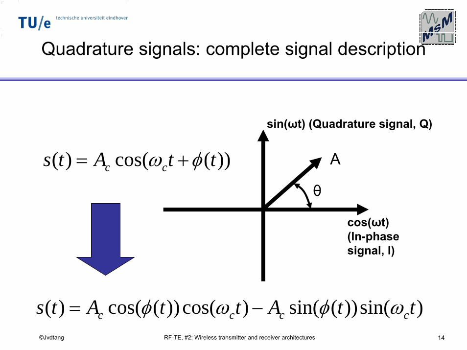
RF-TE, #2: Wireless transmitter and receiver architectures 14©Jvdtang
Quadrature signals: complete signal description
sin(ωt) (Quadrature signal, Q)
))(cos()( ttAts cc φω += A
θ
cos(ωt)(In-phase signal, I)
)sin())(sin()cos())(cos()( ttAttAts cccc ωφωφ −=
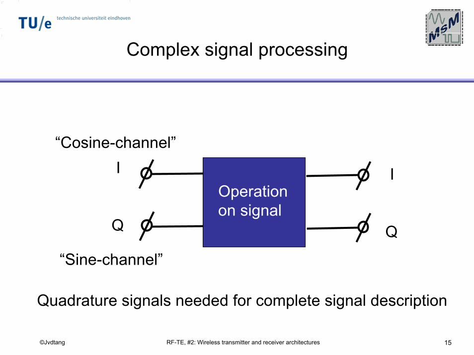
RF-TE, #2: Wireless transmitter and receiver architectures 15©Jvdtang
Complex signal processing
“Cosine-channel”
Operation on signal
I I
Q Q
“Sine-channel”
Quadrature signals needed for complete signal description
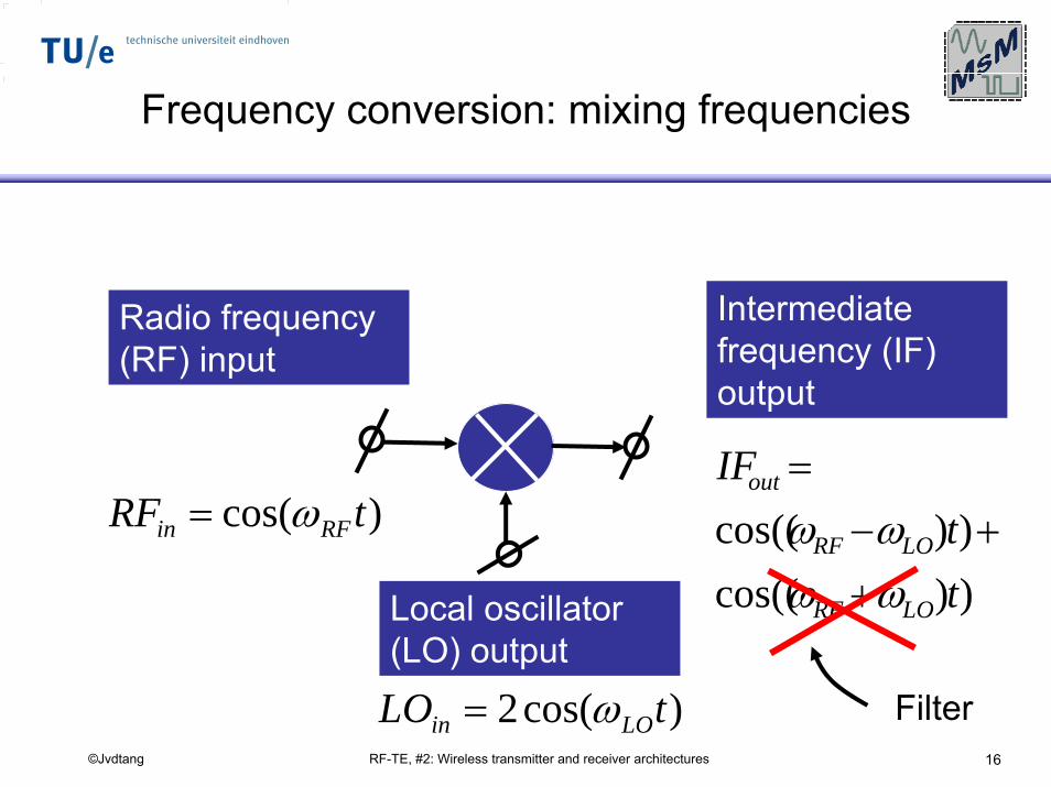
RF-TE, #2: Wireless transmitter and receiver architectures 16©Jvdtang
Frequency conversion: mixing frequencies
Intermediate frequency (IF) output
Radio frequency (RF) input
))cos(())cos((
tt
IF
LORF
LORF
out
ωωωω
++−
=
Local oscillator (LO) output
)cos( tRF RFin ω=
)cos(2 tLO LOin ω= Filter
RF-TE, #2: Wireless transmitter and receiver architectures 17©Jvdtang
RFSampling

RF-TE, #2: Wireless transmitter and receiver architectures 18©Jvdtang
RF sampling (I)
Digitization almost directly at the antenna
Currently, still not feasible / cost-effective given normal constraints for power consumption and cost.
Source: V. Vidojkovic
RF-TE, #2: Wireless transmitter and receiver architectures 19©Jvdtang
RF sampling (II)
• For example, for a Digital European Cordless Telephone (DECT) system, which is working at 1.9 GHz:
– An A/D converter is needed with at least a sampling rate of the nyquist frequency (3.8 GHz) and 14 bits resolution.
When RF sampling becomes cost-effective it will be the most flexible “software-defined” receiver implementation
RF-TE, #2: Wireless transmitter and receiver architectures 20©Jvdtang
Super-heterodyne
receiver
RF-TE, #2: Wireless transmitter and receiver architectures 21©Jvdtang
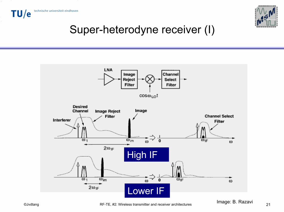
Super-heterodyne receiver (I)
High IF
Lower IFImage: B. Razavi
RF-TE, #2: Wireless transmitter and receiver architectures 22©Jvdtang
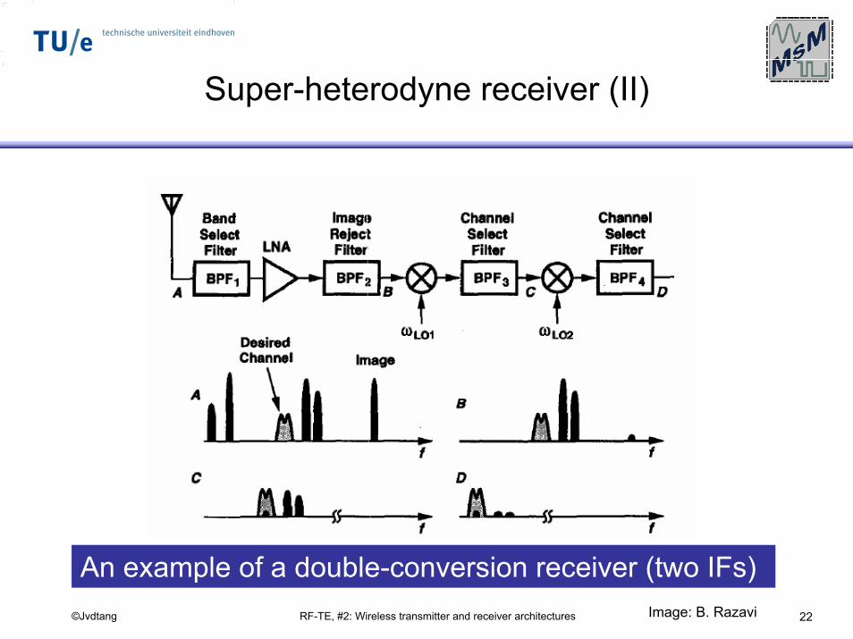
Super-heterodyne receiver (II)
An example of a double-conversion receiver (two IFs)Image: B. Razavi
RF-TE, #2: Wireless transmitter and receiver architectures 23©Jvdtang
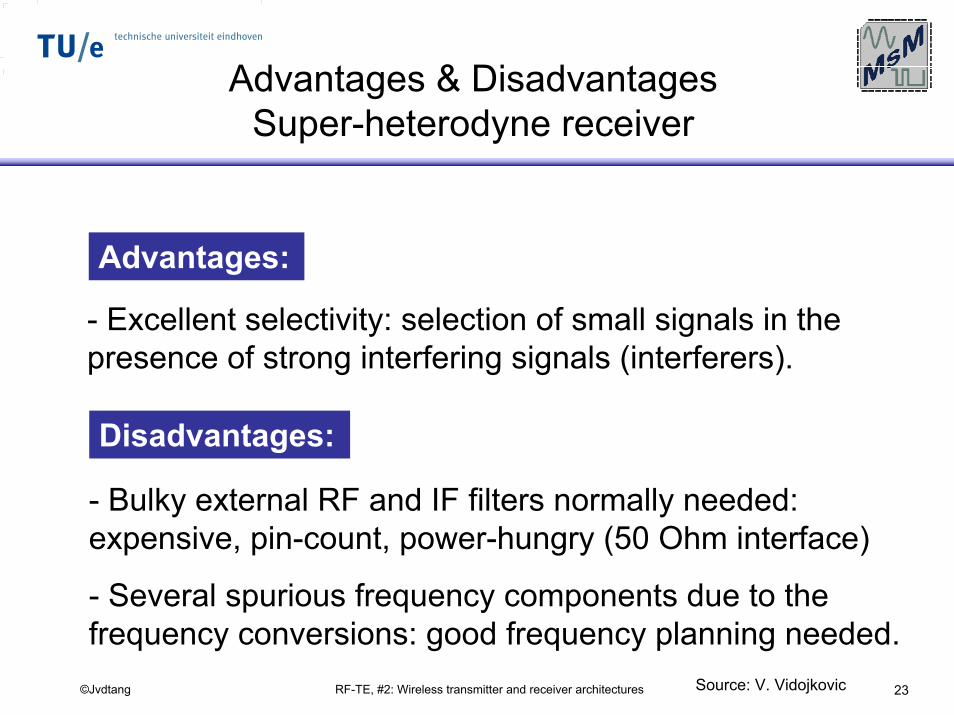
Advantages & Disadvantages Super-heterodyne receiver
Advantages:
- Excellent selectivity: selection of small signals in the presence of strong interfering signals (interferers).
Disadvantages:
- Bulky external RF and IF filters normally needed: expensive, pin-count, power-hungry (50 Ohm interface)
- Several spurious frequency components due to the frequency conversions: good frequency planning needed.
Source: V. Vidojkovic
RF-TE, #2: Wireless transmitter and receiver architectures 24©Jvdtang
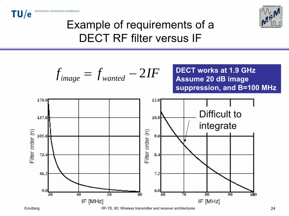
Example of requirements of a DECT RF filter versus IF
IFff wantedimage 2−= DECT works at 1.9 GHzAssume 20 dB image suppression, and B=100 MHz
Difficult tointegrate
RF-TE, #2: Wireless transmitter and receiver architectures 25©Jvdtang
Direct-Conversion
receiver
RF-TE, #2: Wireless transmitter and receiver architectures 26©Jvdtang
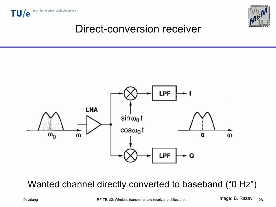
Direct-conversion receiver
Wanted channel directly converted to baseband (“0 Hz”)Image: B. Razavi
RF-TE, #2: Wireless transmitter and receiver architectures 27©Jvdtang
Advantages of direct-conversion
For phase and frequency modulated signals, direct-con-version requires I/Q signals.
Advantages:- No image, since the wanted signal is its image (ωIF=0)
- The IF filter in a super-heterodyne receiver is replaced by low-pass filters
- Low-pass filters are easy to integrate; in general direct-conversion (Zero-IF) receivers allow a high level of integration.
RF-TE, #2: Wireless transmitter and receiver architectures 28©Jvdtang
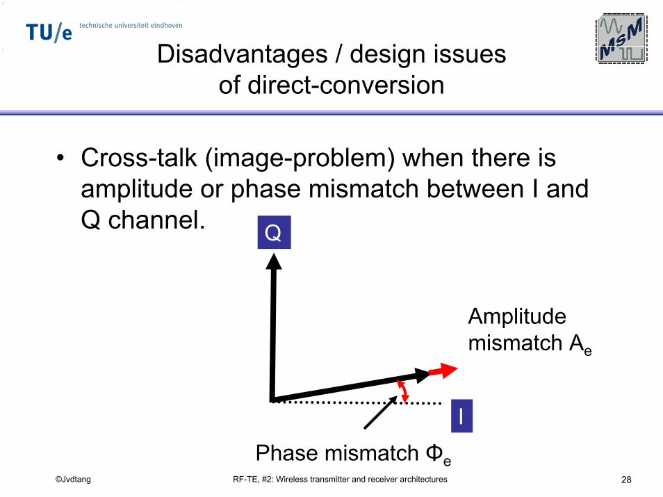
Disadvantages / design issues of direct-conversion
• Cross-talk (image-problem) when there is amplitude or phase mismatch between I and Q channel.
Phase mismatch Φe
I
Q
Amplitude mismatch Ae
RF-TE, #2: Wireless transmitter and receiver architectures 29©Jvdtang
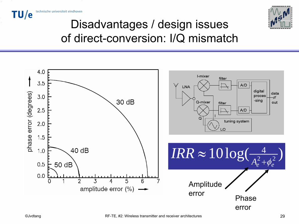
Disadvantages / design issues of direct-conversion: I/Q mismatch
)log(10 224
eeAIRR
φ+≈
Amplitude error Phase
error
RF-TE, #2: Wireless transmitter and receiver architectures 30©Jvdtang
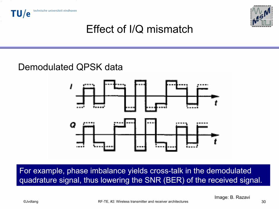
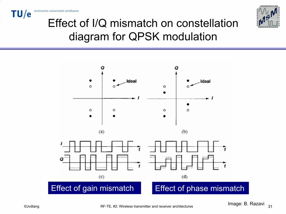
Effect of I/Q mismatch
Demodulated QPSK data
For example, phase imbalance yields cross-talk in the demodulated quadrature signal, thus lowering the SNR (BER) of the received signal.
Image: B. Razavi
RF-TE, #2: Wireless transmitter and receiver architectures 31©Jvdtang
Effect of I/Q mismatch on constellation diagram for QPSK modulation
Effect of gain mismatch Effect of phase mismatch
Image: B. Razavi
RF-TE, #2: Wireless transmitter and receiver architectures 32©Jvdtang
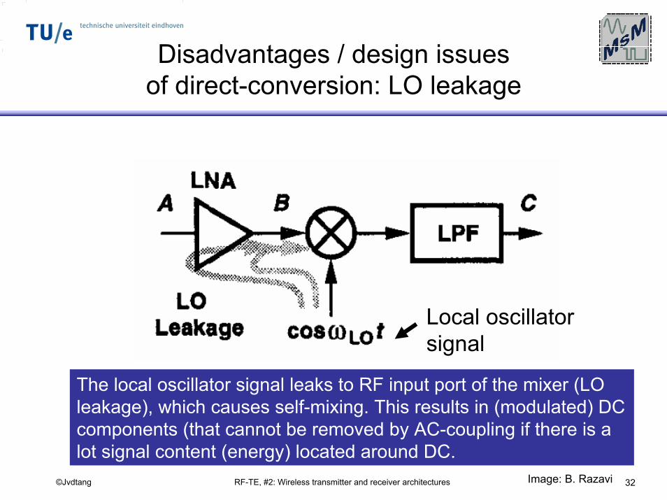
Disadvantages / design issues of direct-conversion: LO leakage
Local oscillatorsignal
The local oscillator signal leaks to RF input port of the mixer (LO leakage), which causes self-mixing. This results in (modulated) DC components (that cannot be removed by AC-coupling if there is a lot signal content (energy) located around DC.
Image: B. Razavi
RF-TE, #2: Wireless transmitter and receiver architectures 33©Jvdtang
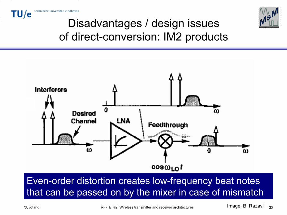
Disadvantages / design issues of direct-conversion: IM2 products
Even-order distortion creates low-frequency beat notes that can be passed on by the mixer in case of mismatch
Image: B. Razavi
RF-TE, #2: Wireless transmitter and receiver architectures 34©Jvdtang
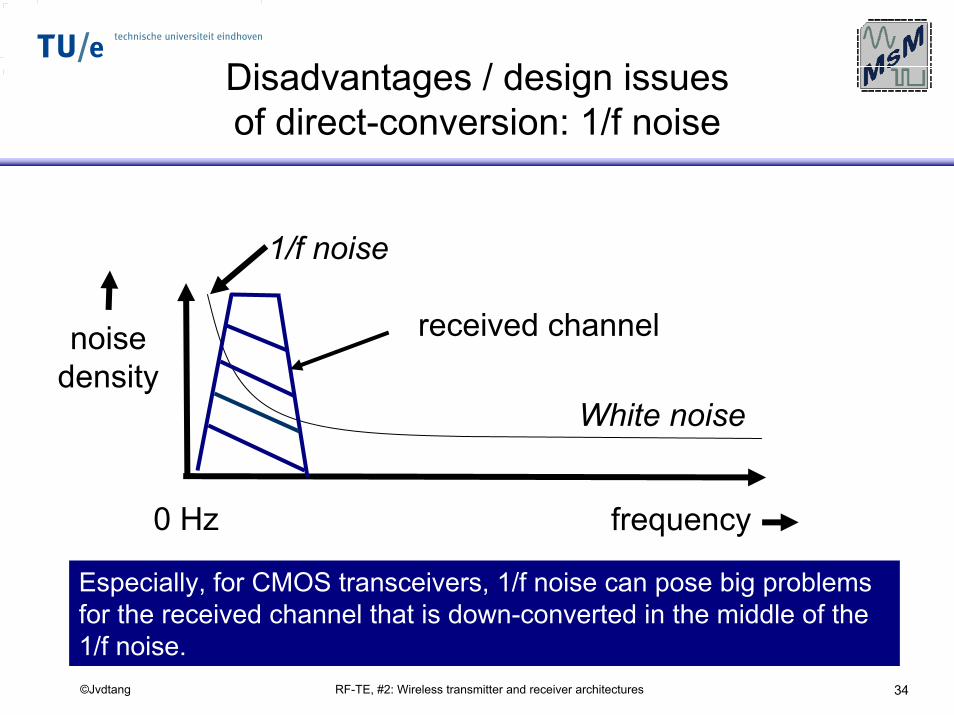
Disadvantages / design issues of direct-conversion: 1/f noise
White noise
1/f noise
received channelnoisedensity
0 Hz frequency
Especially, for CMOS transceivers, 1/f noise can pose big problems for the received channel that is down-converted in the middle of the 1/f noise.
RF-TE, #2: Wireless transmitter and receiver architectures 35©Jvdtang
Direct-conversion: frequently used
• Despite the many design challenges direct-conversion receivers face, they are used in many products.
• The high level of integration it allows is one of the main driving forces behind its use.
• Especially in consumer electronics, costs are a dominant factor; external components are very expensive and influence the bill-of-material (BOM) in a negative sense.
RF-TE, #2: Wireless transmitter and receiver architectures 36©Jvdtang
Low-IFreceivers
RF-TE, #2: Wireless transmitter and receiver architectures 37©Jvdtang
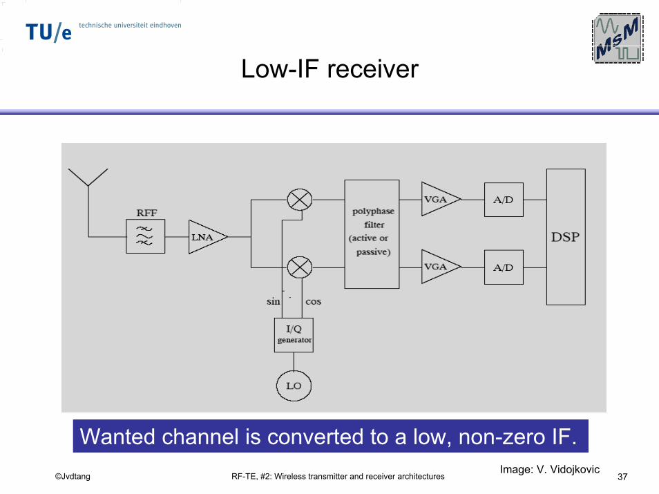
Low-IF receiver
Wanted channel is converted to a low, non-zero IF.Image: V. Vidojkovic
RF-TE, #2: Wireless transmitter and receiver architectures 38©Jvdtang
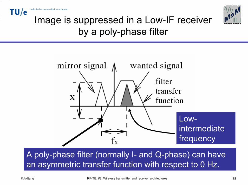
Image is suppressed in a Low-IF receiver by a poly-phase filter
A poly-phase filter (normally I- and Q-phase) can have an asymmetric transfer function with respect to 0 Hz.
Low-intermediatefrequency
RF-TE, #2: Wireless transmitter and receiver architectures 39©Jvdtang
Advantages Low-IF receiver
Advantages:- Image is suppressed by a poly-phase filter, which can be integrated. Because of matching, 30-35 dB image suppression is typical.
- The IF-frequency is not 0 Hz, hence the influence of 1/f noise in the receiver chain is less.
- A high-pass filter may be used after the mixer to remove unwanted DC components, assuming the used modulation allows removal of part of the energy in the spectrum around DC.
RF-TE, #2: Wireless transmitter and receiver architectures 40©Jvdtang
Disadvantages/ design issues of alow-IF receiver
disadvantages:
• Image suppression is limited by I/Q matching (same problem as direct-conversion architectures).
• Poly-phase filters may be power-hungry (relative compared to low-pass filters)
• Poly-phase filters may require a lot of chip area (large capacitors, because of the low-IF).
• Even-order distortion components may still produce unwanted beat notes in the wanted channel, after down-conversion
RF-TE, #2: Wireless transmitter and receiver architectures 41©Jvdtang
Image-reject architectures
RF-TE, #2: Wireless transmitter and receiver architectures 42©Jvdtang
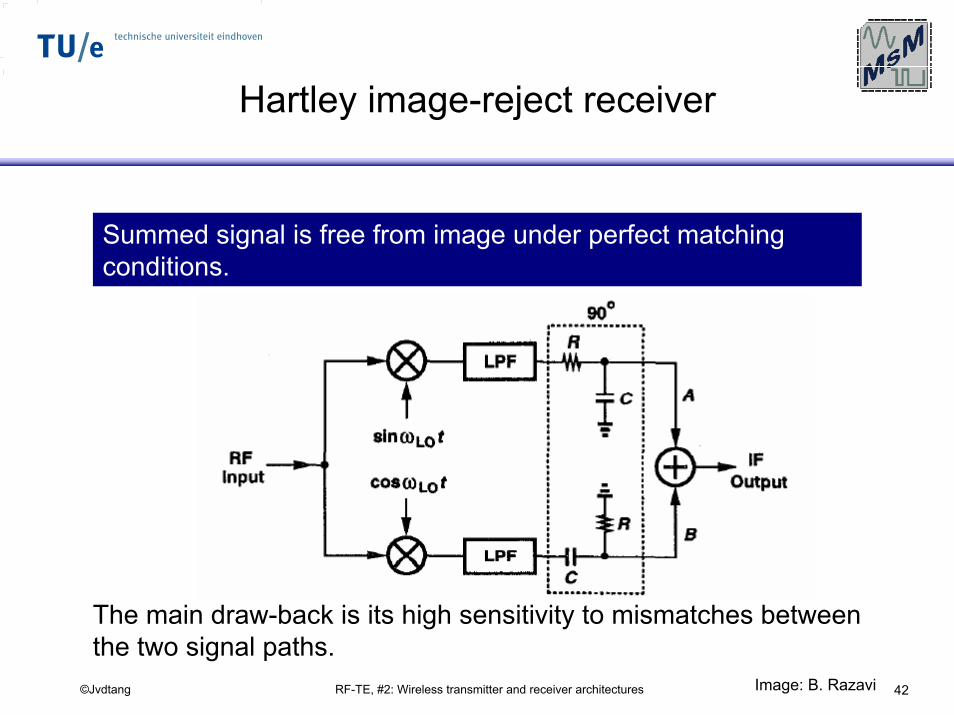
Hartley image-reject receiver
Summed signal is free from image under perfect matching conditions.
The main draw-back is its high sensitivity to mismatches between the two signal paths.
Image: B. Razavi
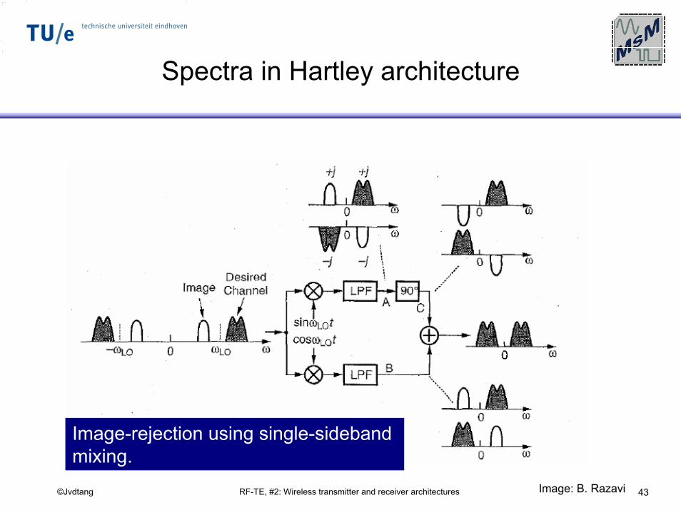
RF-TE, #2: Wireless transmitter and receiver architectures 43©Jvdtang
Spectra in Hartley architecture
Image-rejection using single-sideband mixing.
Image: B. Razavi
RF-TE, #2: Wireless transmitter and receiver architectures 44©Jvdtang
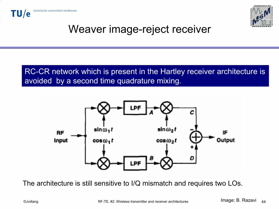
Weaver image-reject receiver
RC-CR network which is present in the Hartley receiver architecture is avoided by a second time quadrature mixing.
The architecture is still sensitive to I/Q mismatch and requires two LOs.
Image: B. Razavi
RF-TE, #2: Wireless transmitter and receiver architectures 45©Jvdtang
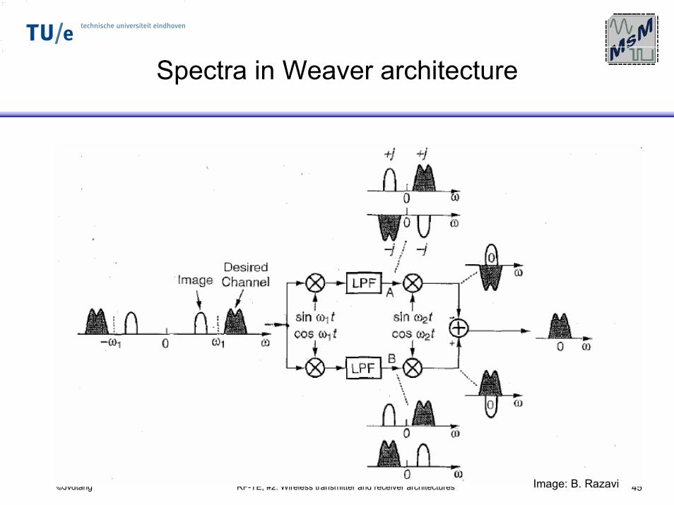
Spectra in Weaver architecture
Image: B. Razavi
RF-TE, #2: Wireless transmitter and receiver architectures 46©Jvdtang
Digital-IF Receiver
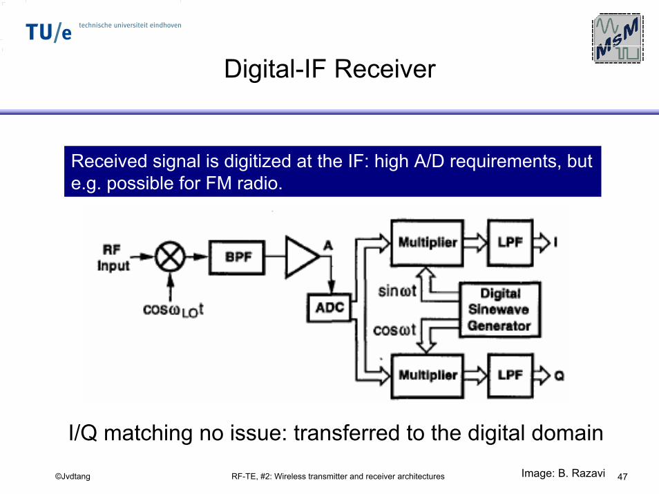
RF-TE, #2: Wireless transmitter and receiver architectures 47©Jvdtang
Digital-IF Receiver
Received signal is digitized at the IF: high A/D requirements, but e.g. possible for FM radio.
I/Q matching no issue: transferred to the digital domainImage: B. Razavi
RF-TE, #2: Wireless transmitter and receiver architectures 48©Jvdtang
Examples of derivative receiver
architectures
RF-TE, #2: Wireless transmitter and receiver architectures 49©Jvdtang
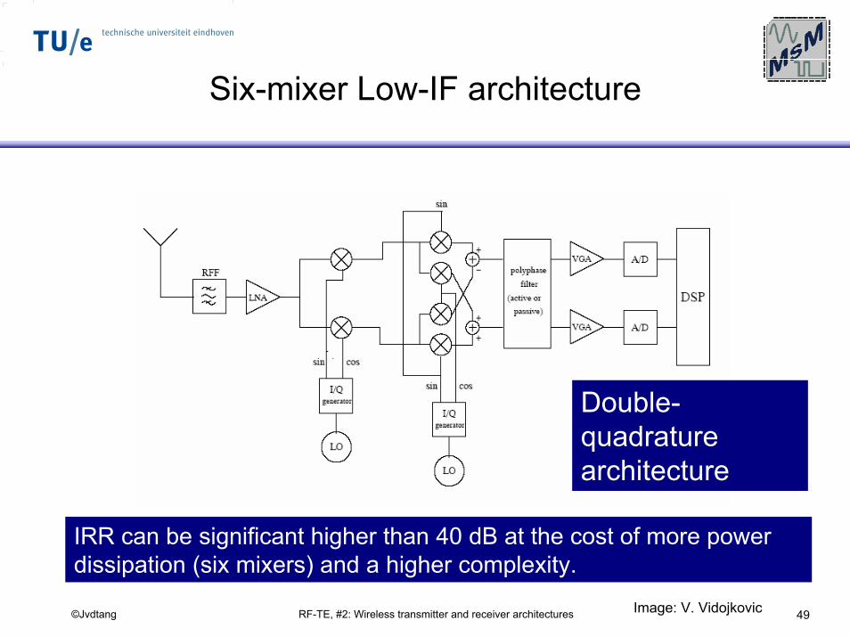
Six-mixer Low-IF architecture
IRR can be significant higher than 40 dB at the cost of more power dissipation (six mixers) and a higher complexity.
Double-quadraturearchitecture
Image: V. Vidojkovic
RF-TE, #2: Wireless transmitter and receiver architectures 50©Jvdtang
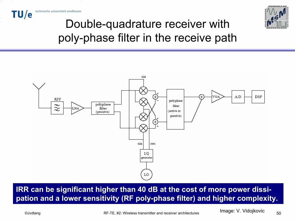
Double-quadrature receiver with poly-phase filter in the receive path
IRR can be significant higher than 40 dB at the cost of more power dissi-pation and a lower sensitivity (RF poly-phase filter) and higher complexity.
Image: V. Vidojkovic
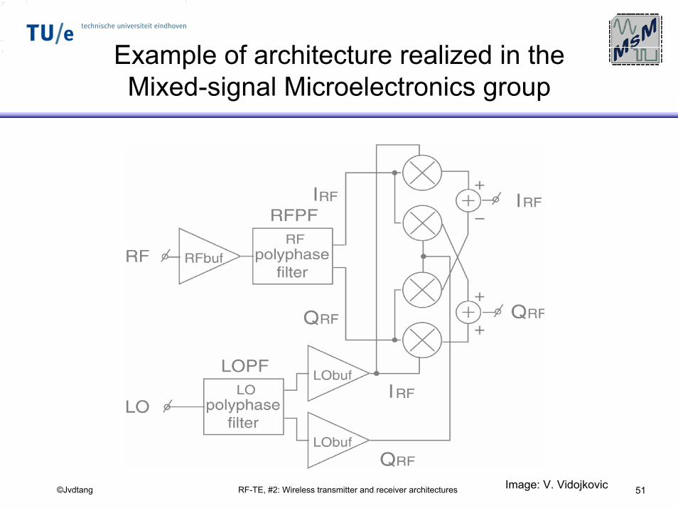
RF-TE, #2: Wireless transmitter and receiver architectures 51©Jvdtang
Example of architecture realized in the Mixed-signal Microelectronics group
Image: V. Vidojkovic
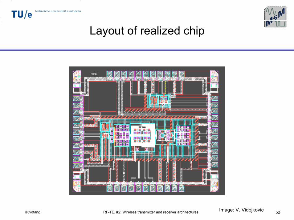
RF-TE, #2: Wireless transmitter and receiver architectures 52©Jvdtang
Layout of realized chip
Image: V. Vidojkovic
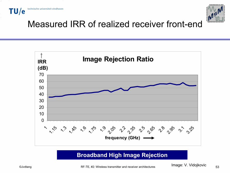
RF-TE, #2: Wireless transmitter and receiver architectures 53©Jvdtang
Measured IRR of realized receiver front-end
Image Rejection Ratio
010203040506070
11.1
5 1.3 1.45 1.6 1.75 1.9 2.05 2.2 2.35 2.5 2.65 2.8 2.95 3.1 3.25
frequency (GHz)
IRR(dB)
Broadband High Image RejectionImage: V. Vidojkovic
RF-TE, #2: Wireless transmitter and receiver architectures 54©Jvdtang
Quadraturegeneration
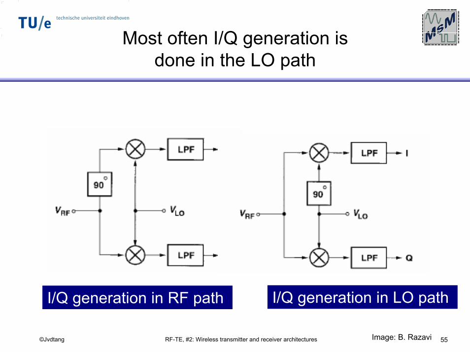
RF-TE, #2: Wireless transmitter and receiver architectures 55©Jvdtang
Most often I/Q generation is done in the LO path
I/Q generation in LO pathI/Q generation in RF path
Image: B. Razavi
RF-TE, #2: Wireless transmitter and receiver architectures 56©Jvdtang
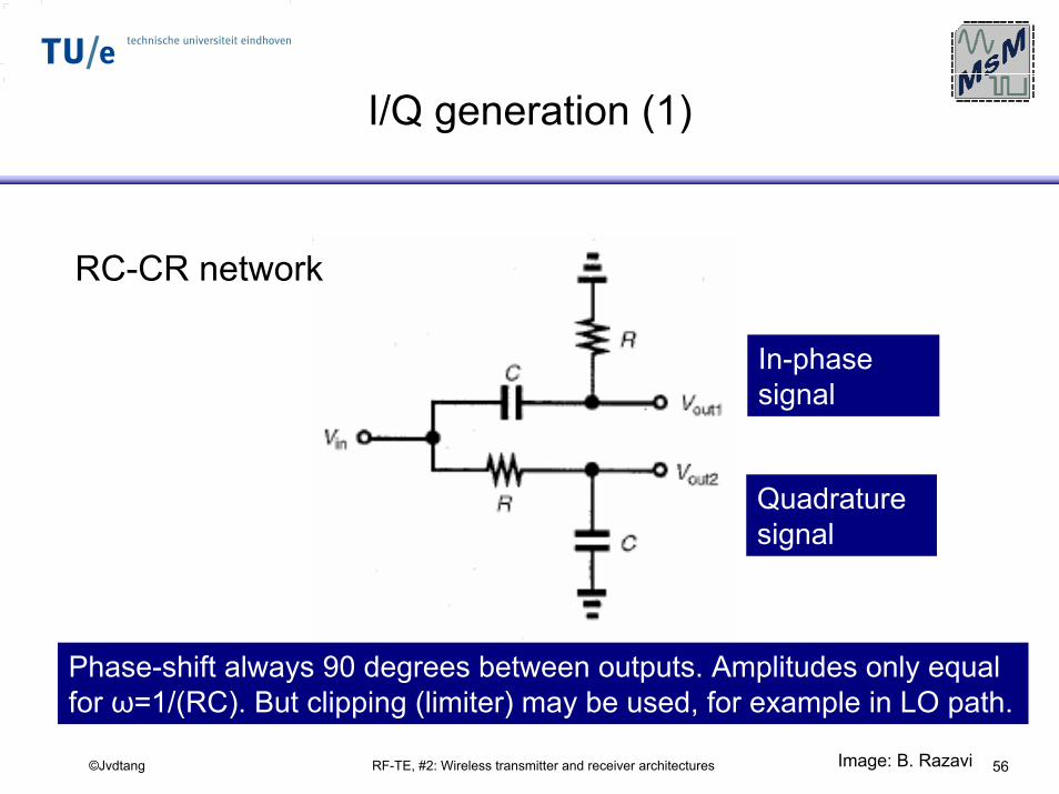
I/Q generation (1)
RC-CR network
Phase-shift always 90 degrees between outputs. Amplitudes only equal for ω=1/(RC). But clipping (limiter) may be used, for example in LO path.
In-phasesignal
Quadraturesignal
Image: B. Razavi
RF-TE, #2: Wireless transmitter and receiver architectures 57©Jvdtang
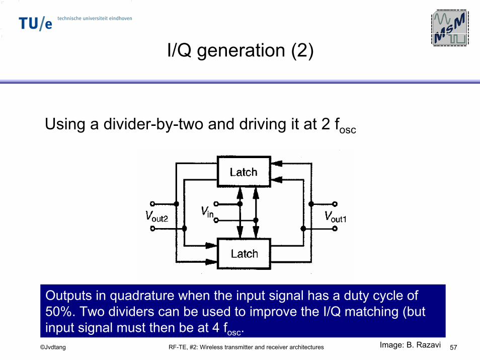
I/Q generation (2)
Using a divider-by-two and driving it at 2 fosc
Outputs in quadrature when the input signal has a duty cycle of 50%. Two dividers can be used to improve the I/Q matching (but input signal must then be at 4 fosc.
Image: B. Razavi
RF-TE, #2: Wireless transmitter and receiver architectures 58©Jvdtang
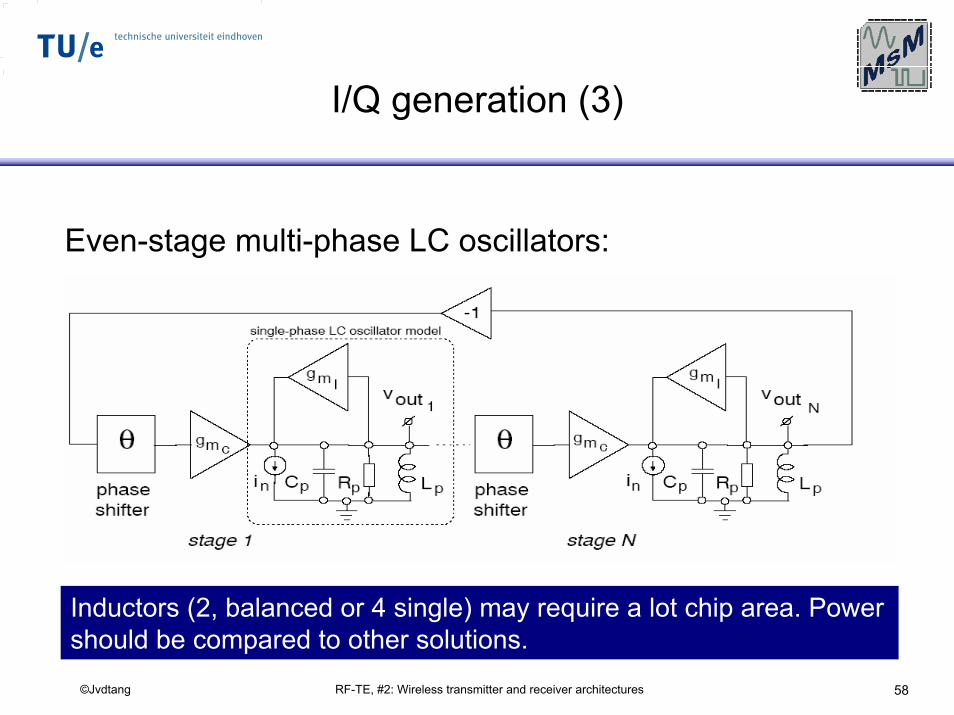
I/Q generation (3)
Even-stage multi-phase LC oscillators:
Inductors (2, balanced or 4 single) may require a lot chip area. Power should be compared to other solutions.
RF-TE, #2: Wireless transmitter and receiver architectures 59©Jvdtang
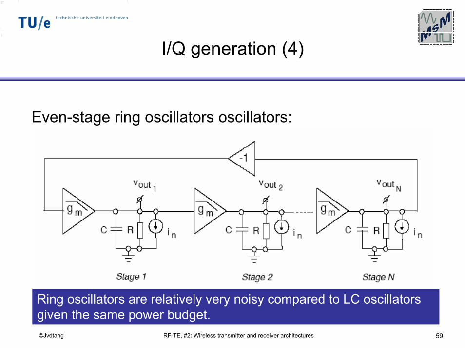
I/Q generation (4)
Even-stage ring oscillators oscillators:
Ring oscillators are relatively very noisy compared to LC oscillators given the same power budget.
RF-TE, #2: Wireless transmitter and receiver architectures 60©Jvdtang
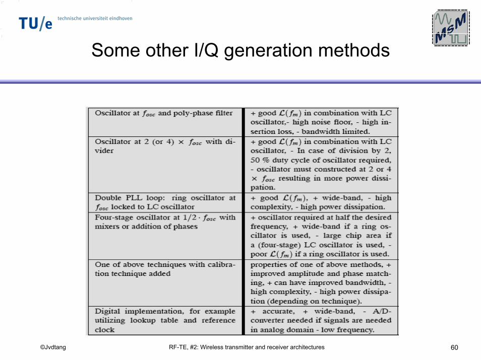
Some other I/Q generation methods
RF-TE, #2: Wireless transmitter and receiver architectures 61©Jvdtang
Transmitter architectures
RF-TE, #2: Wireless transmitter and receiver architectures 62©Jvdtang
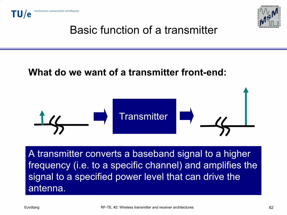
Basic function of a transmitter
What do we want of a transmitter front-end:
Transmitter
A transmitter converts a baseband signal to a higher frequency (i.e. to a specific channel) and amplifies the signal to a specified power level that can drive the antenna.
RF-TE, #2: Wireless transmitter and receiver architectures 63©Jvdtang
BasebandTX
considerations
RF-TE, #2: Wireless transmitter and receiver architectures 64©Jvdtang
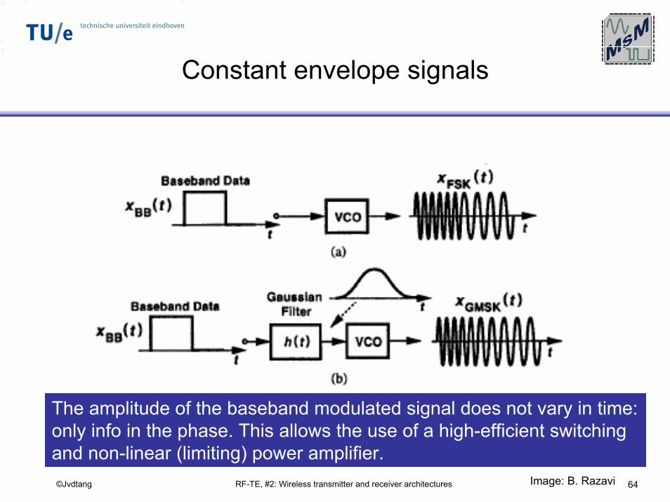
Constant envelope signals
The amplitude of the baseband modulated signal does not vary in time: only info in the phase. This allows the use of a high-efficient switching and non-linear (limiting) power amplifier.
Image: B. Razavi
RF-TE, #2: Wireless transmitter and receiver architectures 65©Jvdtang
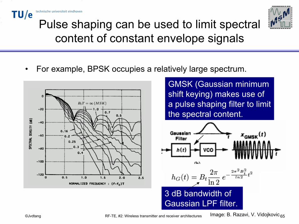
Pulse shaping can be used to limit spectral content of constant envelope signals
• For example, BPSK occupies a relatively large spectrum.
GMSK (Gaussian minimum shift keying) makes use of a pulse shaping filter to limit the spectral content.
3 dB bandwidth of Gaussian LPF filter.
Image: B. Razavi, V. Vidojkovic
RF-TE, #2: Wireless transmitter and receiver architectures 66©Jvdtang
Gaussian minimum shift keying widely used
• Examples of standards– Digital European Cordless Telephone (DECT)– GSM– Hyper-lan– Frequency hoping part of IEEE 802.11
Key advantages is that GSMK (as an example) allows the use of a non-linear, efficient power amplifier while occupying a moderate part of the spectrum. Negative point is that the pulse shaping causes inter-symbol interference (ISI). Using Matched filters in RX and TX helps to minimize ISI.
RF-TE, #2: Wireless transmitter and receiver architectures 67©Jvdtang
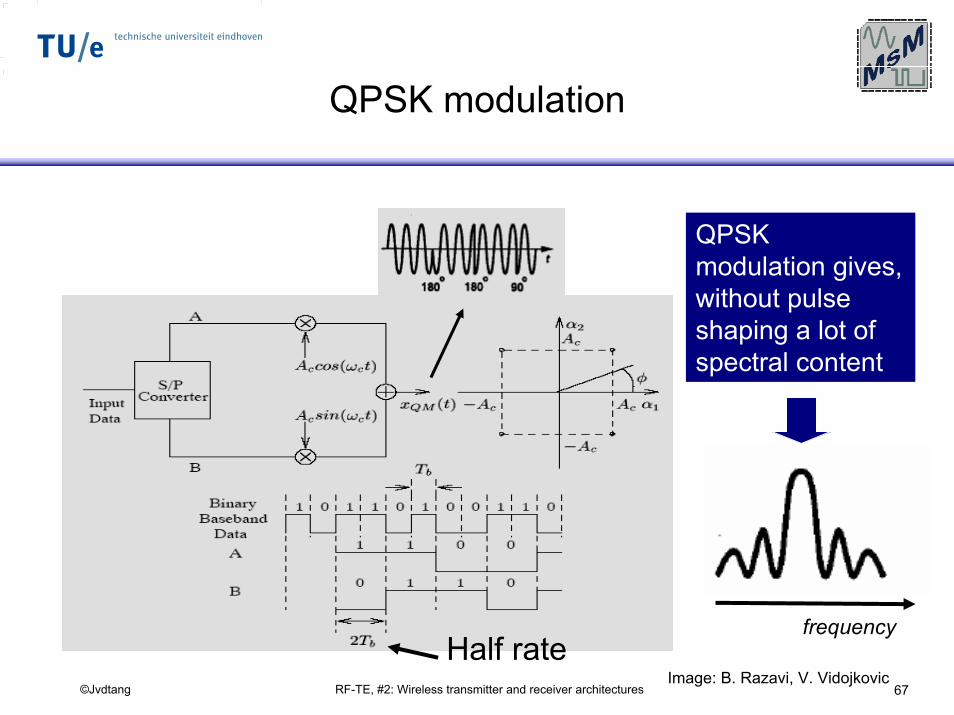
QPSK modulation
QPSK modulation gives, without pulse shaping a lot of spectral content
frequencyHalf rate
Image: B. Razavi, V. Vidojkovic
RF-TE, #2: Wireless transmitter and receiver architectures 68©Jvdtang
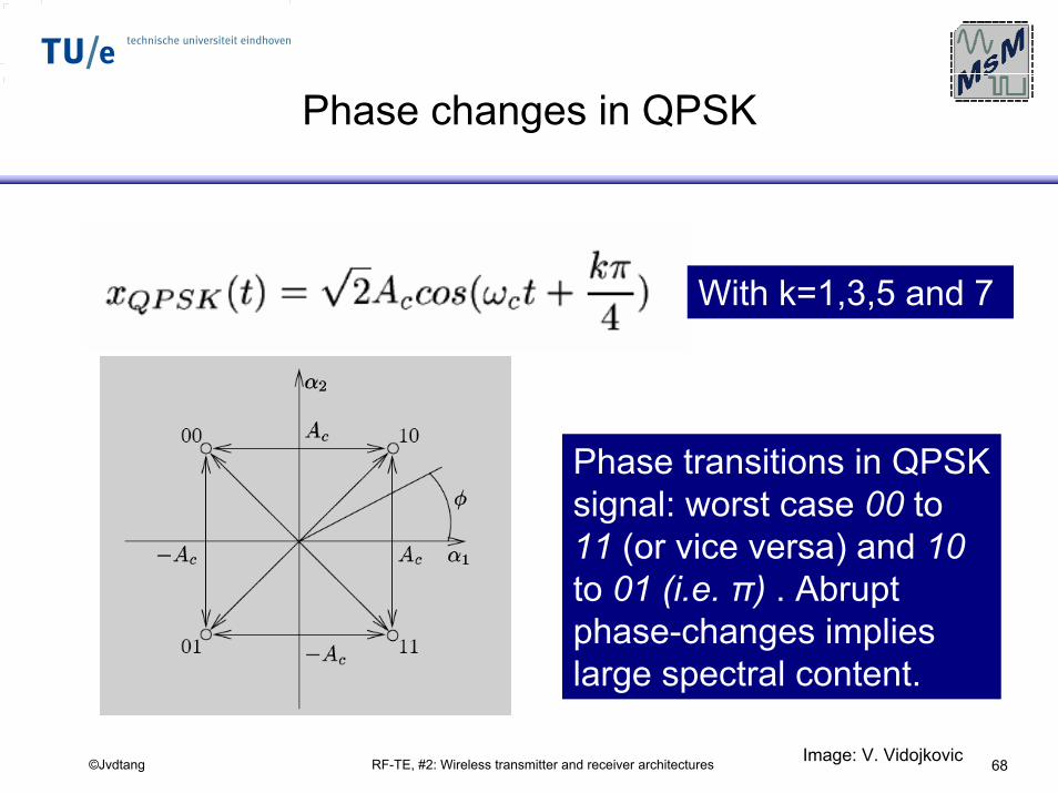
Phase changes in QPSK
With k=1,3,5 and 7
Phase transitions in QPSK signal: worst case 00 to 11 (or vice versa) and 10 to 01 (i.e. π) . Abrupt phase-changes implies large spectral content.
Image: V. Vidojkovic
RF-TE, #2: Wireless transmitter and receiver architectures 69©Jvdtang
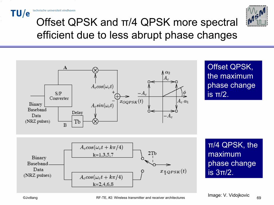
Offset QPSK and π/4 QPSK more spectral efficient due to less abrupt phase changes
Offset QPSK, the maximum phase change is π/2.
π/4 QPSK, the maximum phase change is 3π/2.
Image: V. Vidojkovic
RF-TE, #2: Wireless transmitter and receiver architectures 70©Jvdtang
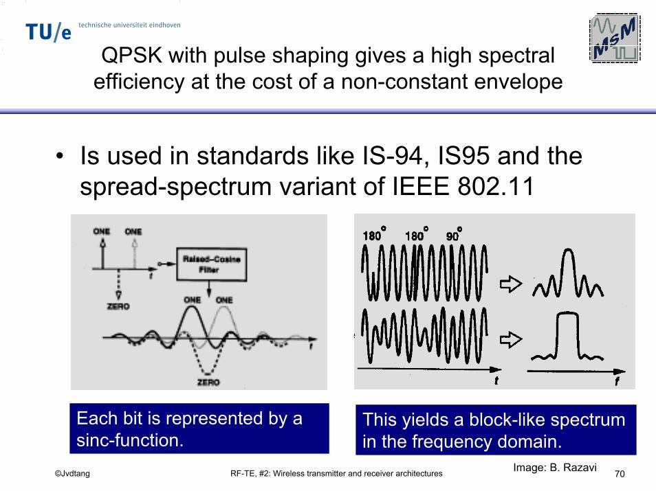
QPSK with pulse shaping gives a high spectral efficiency at the cost of a non-constant envelope
• Is used in standards like IS-94, IS95 and the spread-spectrum variant of IEEE 802.11
Each bit is represented by a sinc-function.
This yields a block-like spectrum in the frequency domain.
Image: B. Razavi
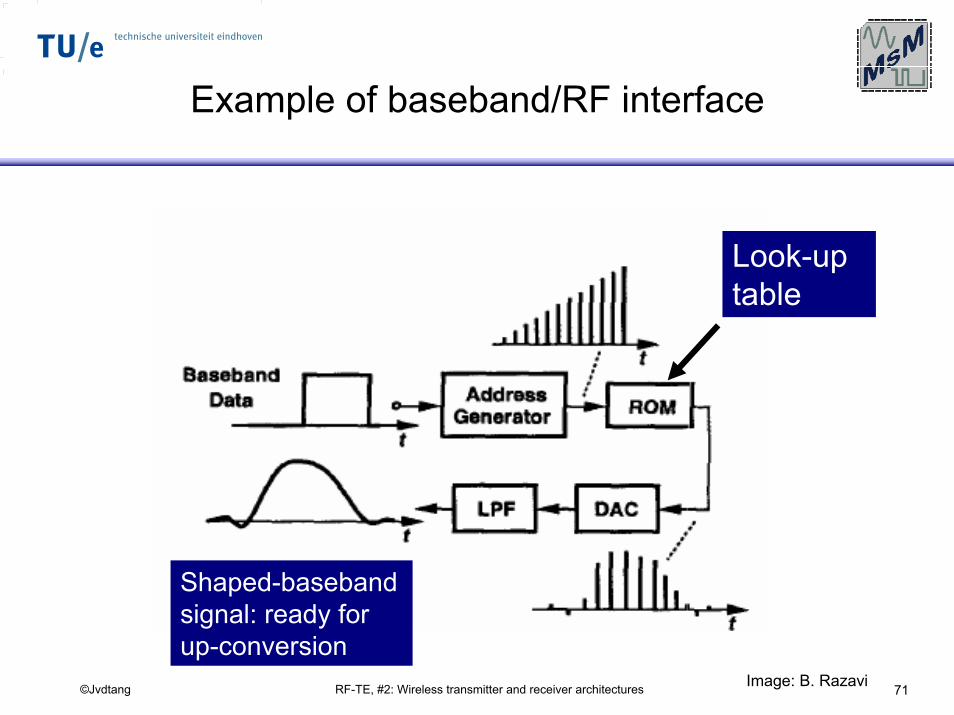
RF-TE, #2: Wireless transmitter and receiver architectures 71©Jvdtang
Example of baseband/RF interface
Look-uptable
Shaped-basebandsignal: ready for up-conversion
Image: B. Razavi
RF-TE, #2: Wireless transmitter and receiver architectures 72©Jvdtang
TX specifications
RF-TE, #2: Wireless transmitter and receiver architectures 73©Jvdtang
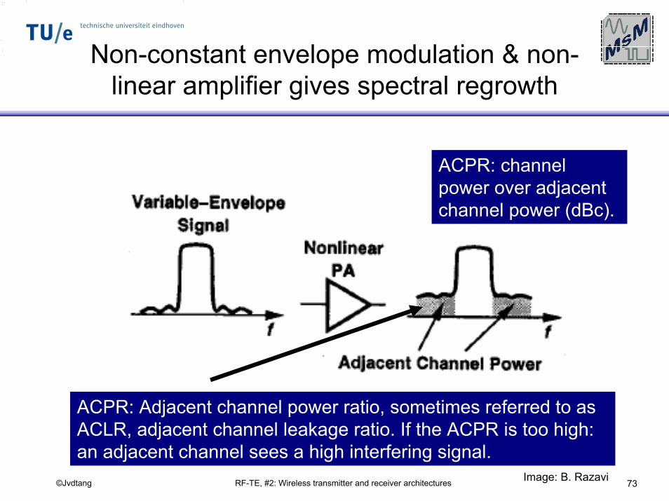
Non-constant envelope modulation & non-linear amplifier gives spectral regrowth
ACPR: channel power over adjacent channel power (dBc).
ACPR: Adjacent channel power ratio, sometimes referred to as ACLR, adjacent channel leakage ratio. If the ACPR is too high: an adjacent channel sees a high interfering signal.
Image: B. Razavi
RF-TE, #2: Wireless transmitter and receiver architectures 74©Jvdtang
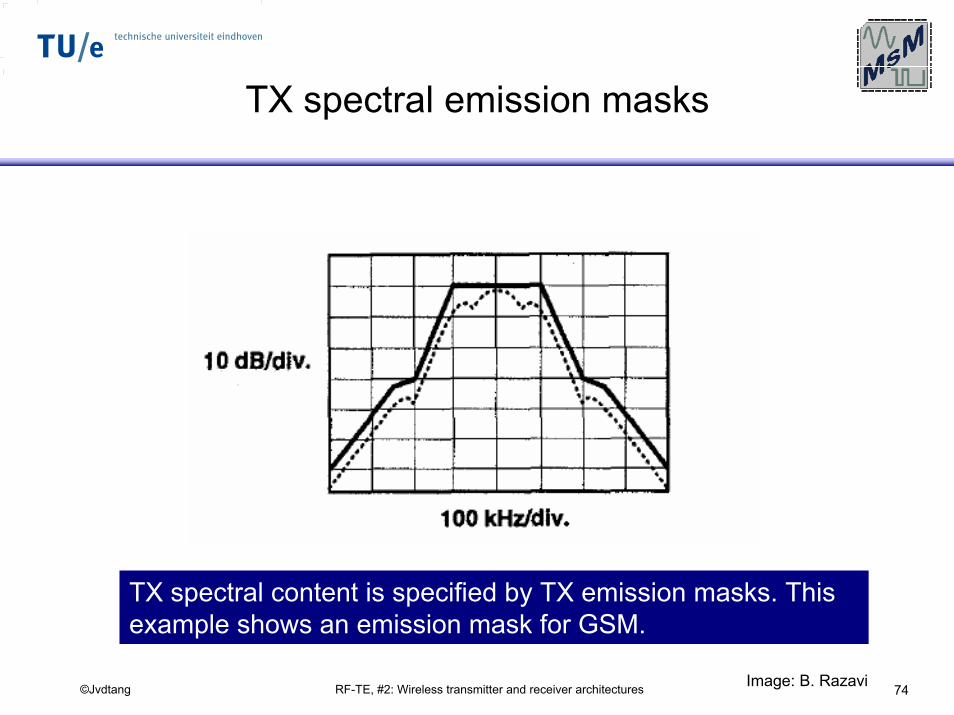
TX spectral emission masks
TX spectral content is specified by TX emission masks. This example shows an emission mask for GSM.
Image: B. Razavi
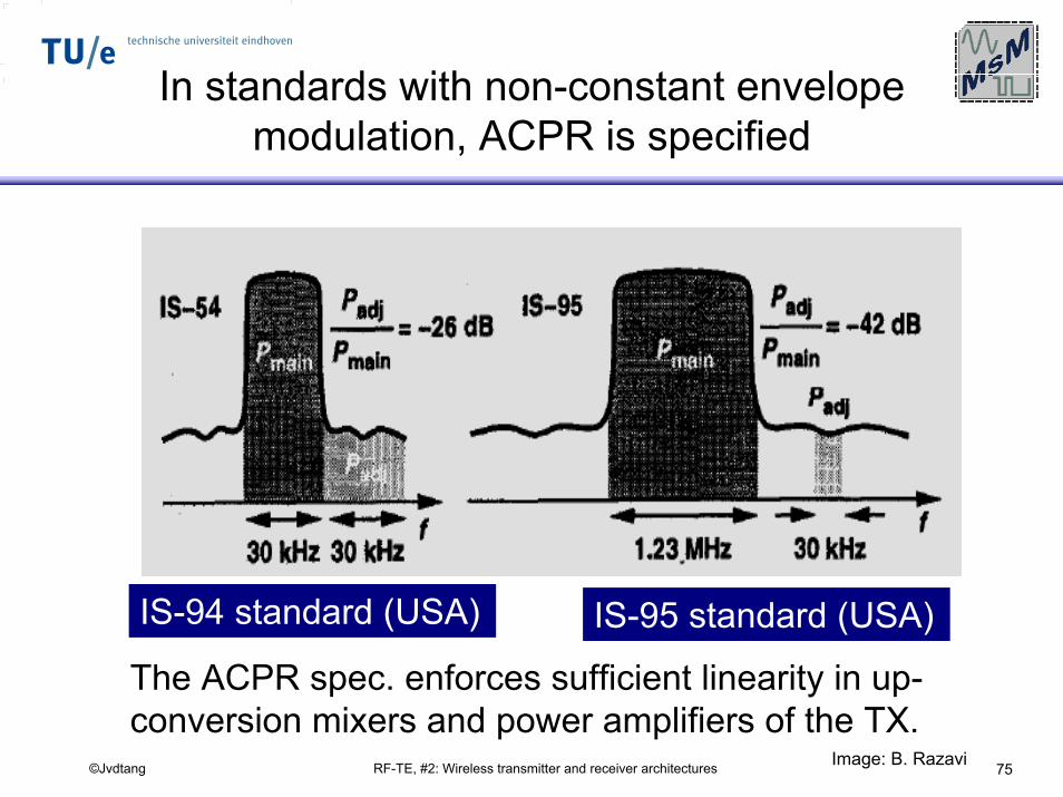
RF-TE, #2: Wireless transmitter and receiver architectures 75©Jvdtang
In standards with non-constant envelope modulation, ACPR is specified
IS-94 standard (USA) IS-95 standard (USA)
The ACPR spec. enforces sufficient linearity in up-conversion mixers and power amplifiers of the TX.
Image: B. Razavi
RF-TE, #2: Wireless transmitter and receiver architectures 76©Jvdtang
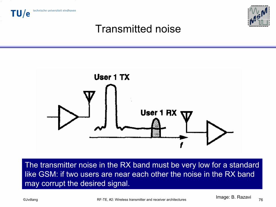
Transmitted noise
The transmitter noise in the RX band must be very low for a standard like GSM: if two users are near each other the noise in the RX band may corrupt the desired signal.
Image: B. Razavi
RF-TE, #2: Wireless transmitter and receiver architectures 77©Jvdtang
General RF TX issues
RF-TE, #2: Wireless transmitter and receiver architectures 78©Jvdtang
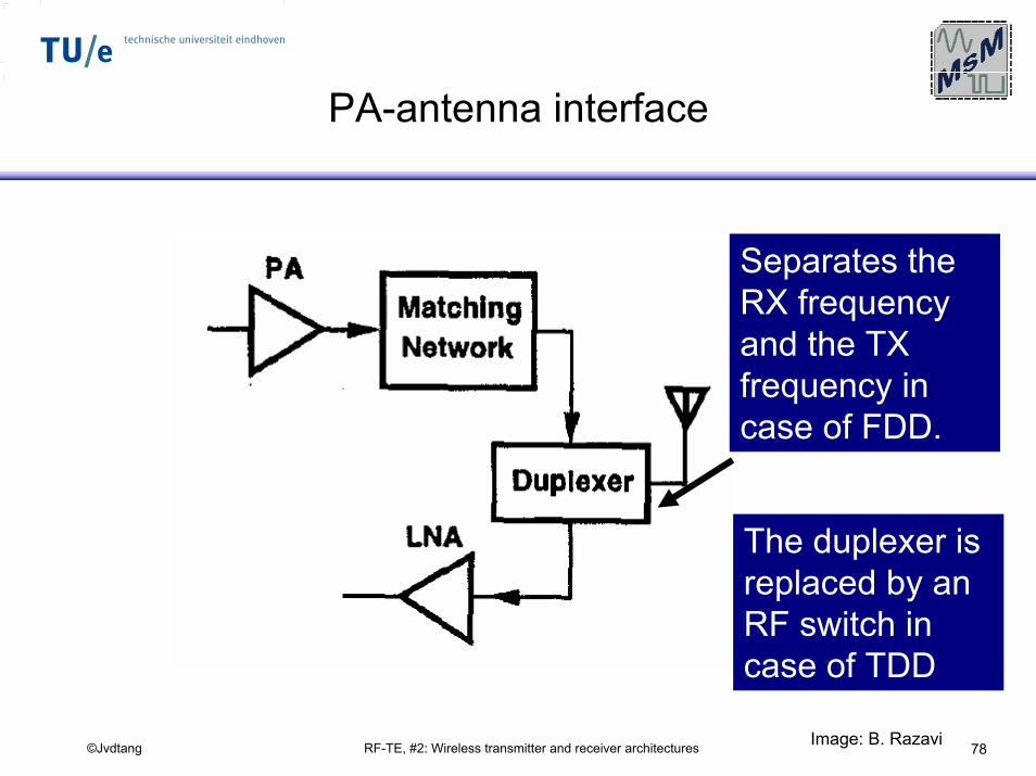
PA-antenna interface
Separates the RX frequency and the TX frequency in case of FDD.
The duplexer is replaced by an RF switch in case of TDD
Image: B. Razavi
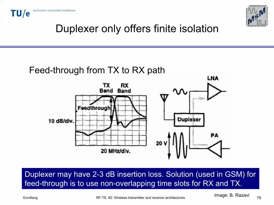
RF-TE, #2: Wireless transmitter and receiver architectures 79©Jvdtang
Duplexer only offers finite isolation
Feed-through from TX to RX path
Duplexer may have 2-3 dB insertion loss. Solution (used in GSM) for feed-through is to use non-overlapping time slots for RX and TX.
Image: B. Razavi
RF-TE, #2: Wireless transmitter and receiver architectures 80©Jvdtang
Direct-conversiontransmitters
RF-TE, #2: Wireless transmitter and receiver architectures 81©Jvdtang
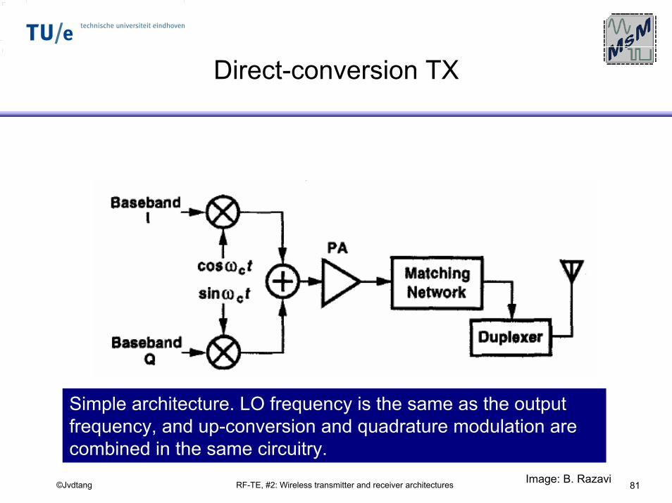
Direct-conversion TX
Simple architecture. LO frequency is the same as the output frequency, and up-conversion and quadrature modulation are combined in the same circuitry.
Image: B. Razavi
RF-TE, #2: Wireless transmitter and receiver architectures 82©Jvdtang
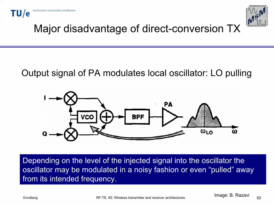
Major disadvantage of direct-conversion TX
Output signal of PA modulates local oscillator: LO pulling
Depending on the level of the injected signal into the oscillator the oscillator may be modulated in a noisy fashion or even “pulled” away from its intended frequency.
Image: B. Razavi
RF-TE, #2: Wireless transmitter and receiver architectures 83©Jvdtang
Direct-conversiontransmitters with
offset LO
RF-TE, #2: Wireless transmitter and receiver architectures 84©Jvdtang
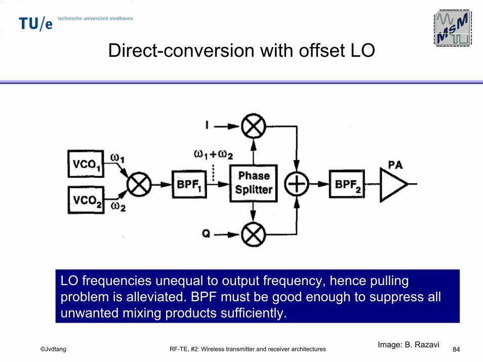
Direct-conversion with offset LO
LO frequencies unequal to output frequency, hence pulling problem is alleviated. BPF must be good enough to suppress all unwanted mixing products sufficiently.
Image: B. Razavi
RF-TE, #2: Wireless transmitter and receiver architectures 85©Jvdtang
Two-step transmitter architecture
RF-TE, #2: Wireless transmitter and receiver architectures 86©Jvdtang
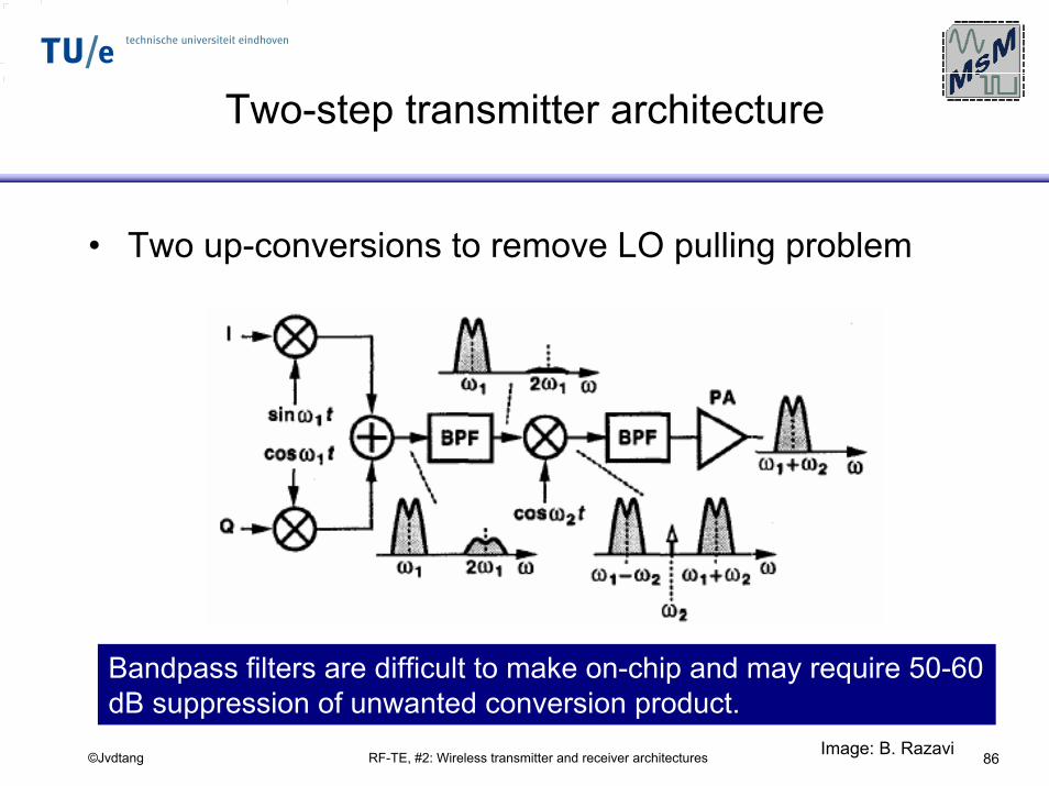
Two-step transmitter architecture
• Two up-conversions to remove LO pulling problem
Bandpass filters are difficult to make on-chip and may require 50-60 dB suppression of unwanted conversion product.
Image: B. Razavi
RF-TE, #2: Wireless transmitter and receiver architectures 87©Jvdtang
Offset-PLL transmitterarchitecture
RF-TE, #2: Wireless transmitter and receiver architectures 88©Jvdtang
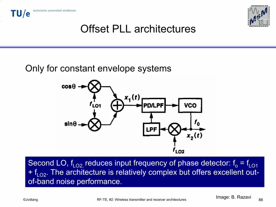
Offset PLL architectures
Only for constant envelope systems
Second LO, fLO2, reduces input frequency of phase detector: fo = fLO1+ fLO2. The architecture is relatively complex but offers excellent out-of-band noise performance.
Image: B. Razavi
RF-TE, #2: Wireless transmitter and receiver architectures 89©Jvdtang
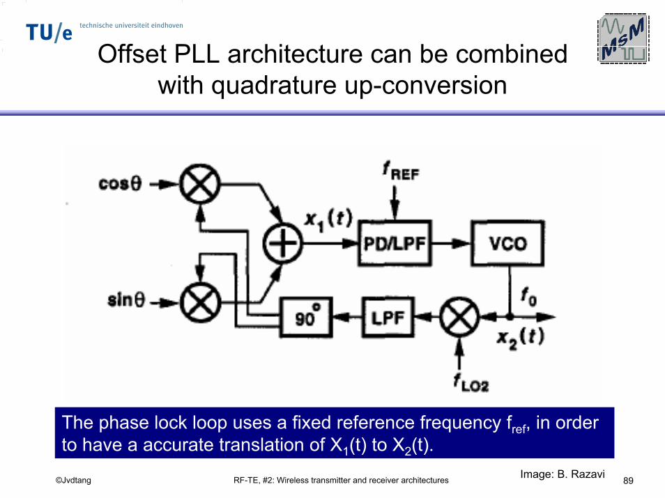
Offset PLL architecture can be combined with quadrature up-conversion
The phase lock loop uses a fixed reference frequency fref, in order to have a accurate translation of X1(t) to X2(t).
Image: B. Razavi
RF-TE, #2: Wireless transmitter and receiver architectures 90©Jvdtang
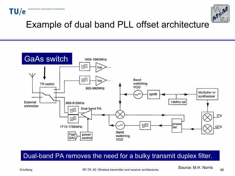
Example of dual band PLL offset architecture
GaAs switch
Dual-band PA removes the need for a bulky transmit duplex filter.Source: M.H. Norris
RF-TE, #2: Wireless transmitter and receiver architectures 91©Jvdtang
Digital transmitter
concept example
RF-TE, #2: Wireless transmitter and receiver architectures 92©Jvdtang
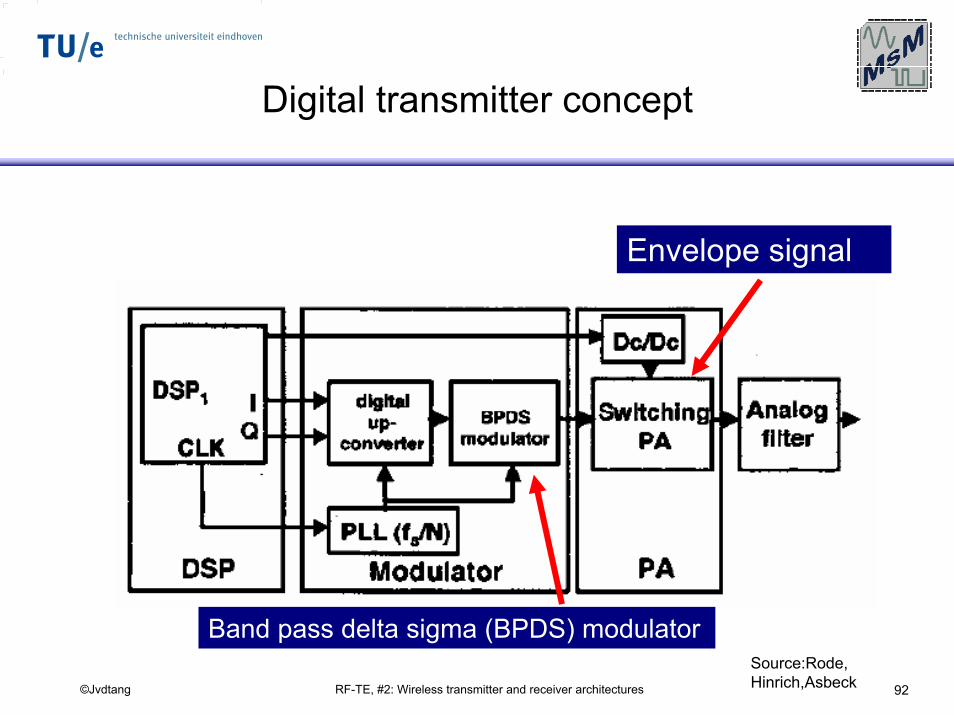
Digital transmitter concept
Envelope signal
Band pass delta sigma (BPDS) modulatorSource:Rode, Hinrich,Asbeck
RF-TE, #2: Wireless transmitter and receiver architectures 93©Jvdtang
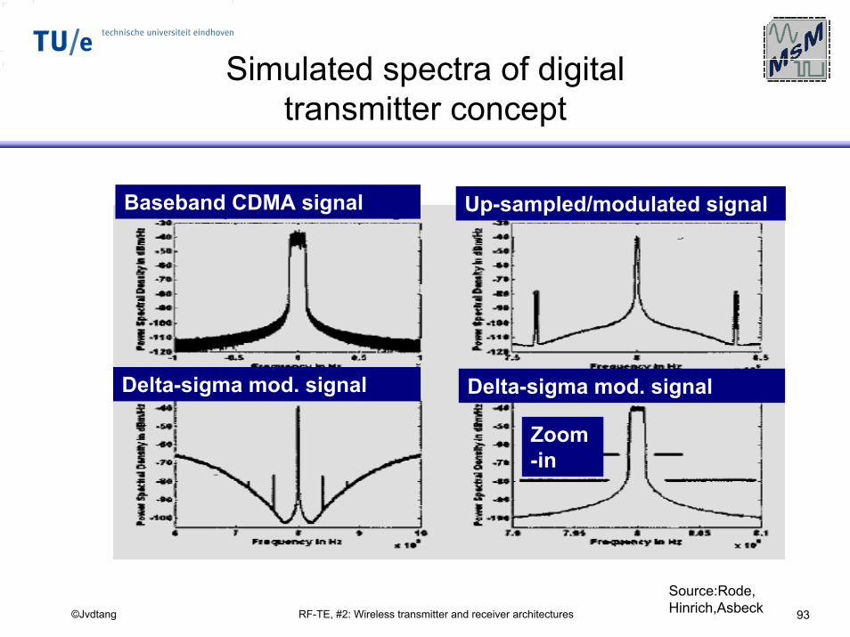
Simulated spectra of digital transmitter concept
Baseband CDMA signal Up-sampled/modulated signal
Delta-sigma mod. signal Delta-sigma mod. signal
Zoom-in
Source:Rode, Hinrich,Asbeck


