34
Vanadium Pentoxide Lithium Coin Type Batteries (VL series) .............. 56 Manganese Lithium Coin Type Batteries (ML series) ....................... 64
| Date post: | 20-Dec-2015 |
| Category: |
Documents |
| Upload: | arqvsegura |
| View: | 239 times |
| Download: | 1 times |
Vanadium Pentoxide Lithium Coin
Type Batteries (VL series) .............. 56
Manganese Lithium Coin Type
Batteries (ML series)....................... 64
Chapter 3
Rechargeable Coin TypeLithium Batteries
INDEXNiobium-Lithium Coin Type
Batteries (NBL series)..................... 72
Manganese Titanium Lithium Coin
Type Batteries (MT series) ............. 74
Ch
apter 3
Chapter 3- 56
Ch
apter 3
3-1 Vanadium Pentoxide Lithium Coin Type Batteries (VL series)
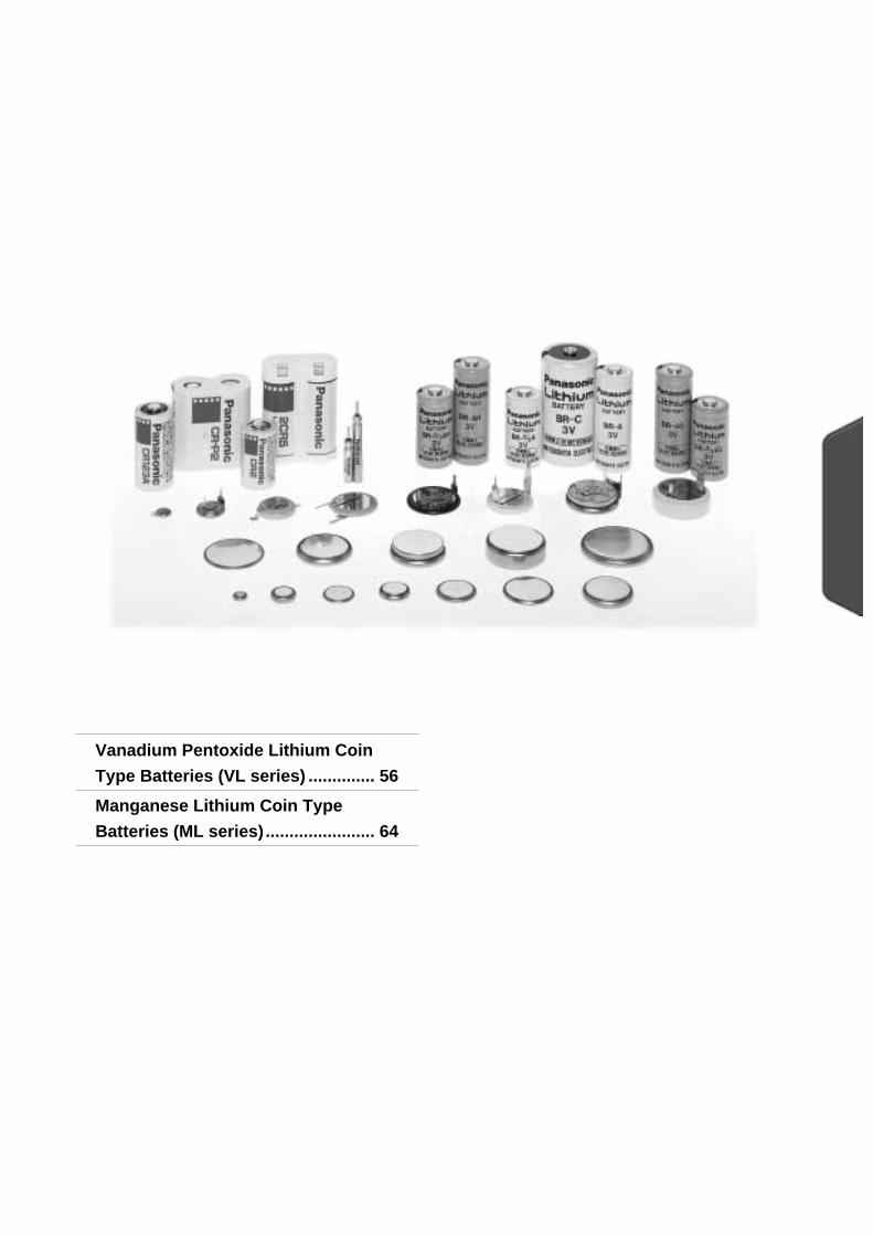
These completely new coin-type lithium batteries feature vanadium oxide for the positive pole, lithium alloy for the
negative pole and a non-aqueous solvent for the electrolyte.
Memory backup power supplies for offi ce automation equipment (personal computers, fax
machines, etc.), audio-video equipment (VTRs, etc.), communications equipment (mobile phones, etc.), etc. Hybrid systems with solar batteries (solar remote con-
trollers, etc.)
+
-
Anode cap
Anode (Li-Al)
Separator
Cell can
Collector
Cathode (V2O5)
Gasket
Features
Construction
Applications
General Specifi cations
Model No.
Electrical characteristics (20°C) Dimensions (mm) Weight (g) JIS IEC
Nominal voltage (V) *Nominal capacity (mAh) Continuous drain (mA) Diameter Height
VL621 3 1.5 0.01 6.8 2.1 0.3 - -
VL1216 3 5.0 0.03 12.5 1.6 0.7 - -
VL1220 3 7.0 0.03 12.5 2.0 0.8 - -
VL2020 3 20.0 0.07 20.0 2.0 2.2 - -
VL2320 3 30.0 0.10 23.0 2.0 2.8 - -
VL2330 3 50.0 0.10 23.0 3.0 3.7 - -
VL3032 3 100.0 0.20 30.0 3.2 6.3 - -
* Nominal capacity shown above is based on standard drain and cut off voltage down to 2.5V at 20°C.
Vanadium Pentoxide Lithium Rechargeable Batteries (VL series)
Van
adiu
m P
ento
xide L
ithiu
m C
oin
Typ
e Batteries (V
L series)

Chapter 3- 57
Ch
apter 3
Charging circuits
Charging
Charging/discharging cycle Approx. 1,000 times at 10% discharge depth to nominal capacity
Charging system* Constant-voltage charging.(Please strictly adhere to the specifi ed charge voltage)
Operating temperature -20 °C ~ + 60 °C
* Consult with Panasonic concerning constant-current charging systems.
The charging circuit is crucial in terms of ensuring that full justice will be done to the battery characteristics.
Consider it carefully as the wrong charging circuit can cause trouble.
Precautions regarding the charge voltage setting
Charge voltage range
Recommended charging circuits
Under no circumstances should trickle charging, which is used for nickel-cadmium batteries, be used. Ignoring
this precaution will cause the battery voltage to rise to about 5V, resulting in a deterioration of performance.
Mixed usage of batteriesDo not use these batteries and lithium primary batteries or other rechargeable batteries together, and do
not use new batteries and old batteries together even if they are of the same type.
Van
adiu
m P
ento
xide L
ithiu
m C
oin
Typ
e Batteries (V
L series)
If a fi xed-charging method is applied, please adhere to the specifi ed charging voltage.
The guaranteed value over an operating temperature range from -20 to +60°C is 3.4V ± 0.15V.
(Actual value: 3.4V ± 0.20V)
* If the charging voltage exceeds the specifi cations, the internal resistance of the battery will rise and may
cause battery deterioration. Also,with a charge voltage around 4V, corrosion of the (+) terminal (case) may
occur, causing leakage. ("Infl uence of the charge voltage on VL batteries" in Chapter 3-59.)
* It is not possible for the battery capacity to recover completely when the charging voltage is below the
specifi cation.
Basic conditions
Charge voltage: 3.4V±0.15V
Charge current: For a battery voltage of 3V
VL621 Approx. 0.2 mA or below
VL1216, VL1220 Approx. 0.5 mA or below
VL2020 Approx. 1.5 mA or below
VL2320, VL2330 Approx. 2.0 mA or below
VL3032 Approx. 4.0 mA or below
(It is permissible for the current to increase beyond the above level when the battery voltage drops below 3V.)
VL
0V
5V
wrong
VL
0V
3.4V
3.6V
right
Chapter 3- 58
Ch
apter 3
Reference: Examples of 5-V charging circuits
Charging
Van
adiu
m P
ento
xide L
ithiu
m C
oin
Typ
e Batteries (V
L series)
ZD
3
2D1D
2R1R
VL
5V
3D
( + )
( - )1.6k560
2
2
R1.5k470A
B
270B MA3036H MA700300A MA3036L MA704
1R1ZD D
2
2R
1R VL
5V
D
( + )
( - )
68180120510VL30321503902701100VL2320, VL2330
1804703301300VL2020
56015005102000VL1220, VL1216
2.7k6.8k2.4k8.2kVL621
2R1R2R1R
1
2D1D
2R
1R
VL
5V
3D
( + )
( - )
16068VL3032390150VL2320, VL2330510200VL2020
2000750VL1220, VL12165.6k2.2kVL621
2R1R
VL
R
7
4
0V
8
5 6
3.6VR 1 : 4.3k R 2 : 15.0k R 3 : 680
VL
R1
0V
5V
R2
R3
3.4V
3.4V
VL
R
0V
5V
LEDLED
VL
R
0V
5V
ZD
DD
7.5V
VL
R
D
0V
GND
~3.4V
REG D
3.7V MA700
VL3032 VL2330 VL2320 VL2020 VL1220 VL1216 VL621
For details, refer to the constant voltage element specifications
()
Standard circuitsFor D2 , select a diode of small inverse current
Simple economical circuits
Load with 5V applied
D : MA700 (Very small inverse current)
LoadLoad
Load
Load
Load
Load
Load
Load
D3 : MA704, MA700D1, D2 : MA716(Diode type code)
(IR=1 A below / 5V)
For D , select a diode of small inverse current (IR=1 A below / 5V)
100 A below
D,Vf
Common to all types
Type
Not required
Not required
For minimizing current leakage due to resistance, etc., as when charging by another battery.
Constant voltageelement
Shotkey
LED controlZener control
Select a diode having an inverse current as small as possible.(IR=1 A below / 5V)
ZD : HZ2ALL R : 43 /VL2320
D : MA700 or MA704
Patent pending
68 /VL2020R=51 for VL2320D : MA700 or MA704
Parallel circuitTransistor control(for VL2320)
100 A~10mA
0.2V~0.6V 0~0.2V
Chapter 3- 59
Ch
apter 3
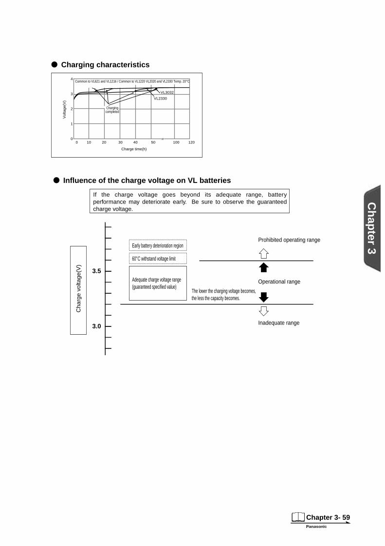
Charging characteristics
VL3032
VL2330
4
3
2
1
0403020100 50 100 120
Common to VL621 and VL1216 / Common to VL1220 VL2020 and VL2330 Temp. 20°C
Chargingcompleted
Vol
tage
(V)
Charge time(h)
Infl uence of the charge voltage on VL batteries
3.5
3.0
If the charge voltage goes beyond its adequate range, battery performance may deteriorate early. Be sure to observe the guaranteed charge voltage.
Early battery deterioration region
Adequate charge voltage range(guaranteed specified value)
60˚C withstand voltage limit
The lower the charging voltage becomes,the less the capacity becomes.
Cha
rge
volta
ge(V
)
Prohibited operating range
Operational range
Inadequate range
Charging
Van
adiu
m P
ento
xide L
ithiu
m C
oin
Typ
e Batteries (V
L series)
Chapter 3- 60
Ch
apter 3
Dimensions(mm)
Specifi cation
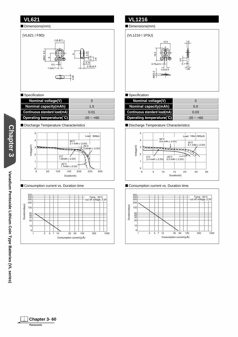
VL621 Dimensions(mm)
Specifi cation
VL1216
+- +-
Discharge Temperature Characteristics Discharge Temperature Characteristics
Consumption current vs. Duration time Consumption current vs. Duration time
(VL621 / F9D) (VL1216 / 1F5U)
3
1.5
0.01
-20 ~ +60
3
5.0
0.03
-20 ~ +60
Van
adiu
m P
ento
xide L
ithiu
m C
oin
Typ
e Batteries (V
L series)
Chapter 3- 61
Ch
apter 3
Dimensions(mm)
Specifi cation
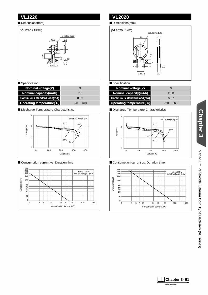
VL1220 Dimensions(mm)
Specifi cation
VL2020
Discharge Temperature Characteristics
Consumption current vs. Duration time
Discharge Temperature Characteristics
Consumption current vs. Duration time
+ -
(VL1220 / 1F5U) (VL2020 / 1VC)
3
7.0
0.03
-20 ~ +60
3
20.0
0.07
-20 ~ +60
Van
adiu
m P
ento
xide L
ithiu
m C
oin
Typ
e Batteries (V
L series)
Chapter 3- 62
Ch
apter 3
Dimensions(mm)
Specifi cation
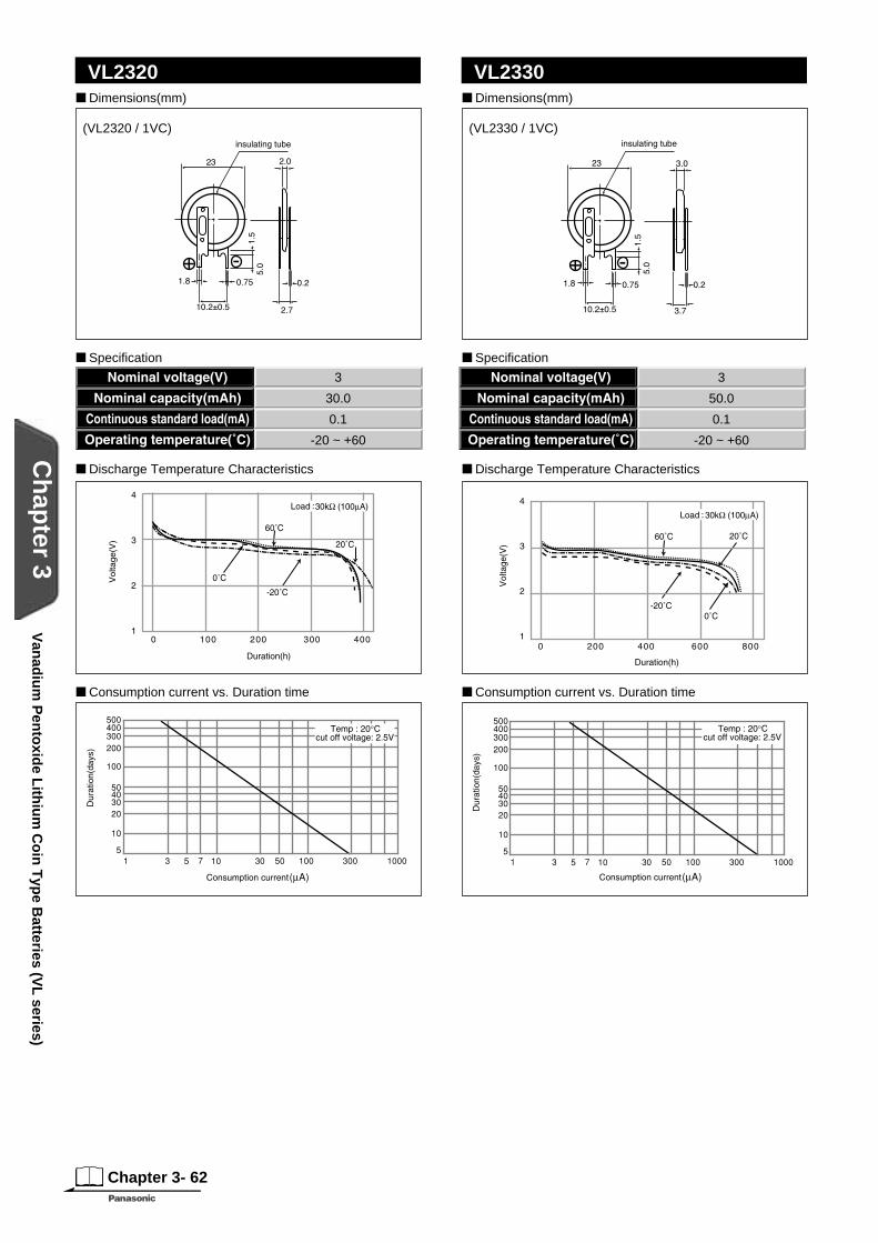
VL2320 Dimensions(mm)
Specifi cation
VL2330
(VL2320 / 1VC) (VL2330 / 1VC)
Discharge Temperature Characteristics Discharge Temperature Characteristics
Consumption current vs. Duration time Consumption current vs. Duration time
3
30.0
0.1
-20 ~ +60
3
50.0
0.1
-20 ~ +60
Van
adiu
m P
ento
xide L
ithiu
m C
oin
Typ
e Batteries (V
L series)
Chapter 3- 63
Ch
apter 3
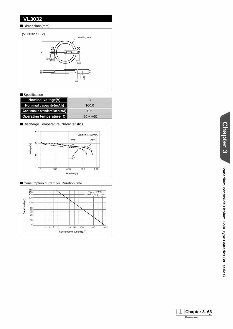
Dimensions(mm)
VL3032
+ -
Specifi cation
(VL3032 / 1F2)
Discharge Temperature Characteristics
Consumption current vs. Duration time
3
100.0
0.2
-20 ~ +60
Van
adiu
m P
ento
xide L
ithiu
m C
oin
Typ
e Batteries (V
L series)
Chapter 3- 64
Ch
apter 3
3-2 Manganese Lithium Coin Type Batteries (ML series)
These super compact lithium rechargeable batteries feature a manganese compound oxide for the
positive electrode, a lithium/aluminum alloy for the negative electrode and a special non-aqueous
solvent for the electrolyte. They can easily be incorporated into circuits where 3V ICs are used
to save space.
Memory backup power supplies for mobile phones, memory
cards, pagers and other compact communications equipment,
data terminals and offi ce automation equipment
Features
Applications
General Specifi cations
Model No.
Electrical characteristics (20°C) Dimensions(mm) Weight(g) JIS IEC
Nominal voltage(V) *Nominal capacity(mAh) Continuous drain(mA) Diameter Height
ML612S 3 2.6 0.01 6.8 1.2 0.15 - -
ML614S 3 3.4 0.01 6.8 1.4 0.17 - -
ML616S 3 2.9 0.01 6.8 1.6 0.2 - -
ML621S 3 5.0 0.01 6.8 2.1 0.3 - -
ML920S 3 11.0 0.03 9.5 2.0 0.5
ML1220 3 17.0 0.03 12.5 2.0 0.8
ML2020 3 45.0 0.10 20.0 2.0 2.2 - -
ML2430(Under development) 3 120.0 0.30 24.5 3.0 4.0
*Nominal capacity shown above is based on standard drain and cut off voltagedown to 2.0V at 20°C.
Man
gan
ese Lith
ium
Co
in T
ype B
atteries (ML
series)
Manganese Lithium Rechargeable Batteries (ML series)

Chapter 3- 65
Ch
apter 3
Charging
Charging circuits
* Consult with Panasonic concerning constant-current charging systems.
The charging circuit is crucial in terms of ensuring that full justice will be done to the battery characteristics.
Consider it carefully as the wrong charging circuit can cause trouble.
Precautions regarding the charge voltage setting
Charge voltage range
Recommended charging circuits
Under no circumstances should trickle charging, which is used for nickel-cadmium batteries, be used.
Ignoring this precaution will cause the battery voltage to rise to about 5V, resulting in a deterioration of performance.
If a fi xed-charging method is applied, please adhere to the specifi ed charging voltage.
Guaranteed voltage is 2.8V ~ 3.2V at the temperature of -20°C~60°C.
* If the charging voltage exceeds the specifi cations, the internal resistance of the battery will rise and may cause
battery deterioration. Also, with a charge voltage around 4V, corrosion of the (+)terminal (case) may occur,
causing leakage. ("Infl uence of the charge voltage on ML batteries" on the back.)
* It is not possible for the battery capacity to recover completely when the charging voltage is below
the specifi cation.
Basic conditions
Fixed-voltage charge
Charge voltage: 2.8~3.2V (Standard voltage: 3.1V)
Charge current: For a battery voltage of 2.5V
ML612S,ML614S,ML616S Approx. 0.3 mA or below
ML621S Approx. 0.6 mA or below
ML920S Approx. 1.2 mA or below
ML1220 Approx. 1.2 mA or below
ML2020 Approx. 3.0 mA or below
Mixed usage of batteries
Do not use these batteries and lithium primary batteries or other rechargeable batteries together, and do
not use new batteries and old batteries together even if they are of the same type.
Man
gan
ese Lith
ium
Co
in T
ype B
atteries (ML
series)
Charging/discharging cycle Approx. 1,000 times at 10% discharge depth to nominal capacity
Charging system* Constant-voltage charging.(Please strictly adhere to the specifi ed charge voltage)
Operating temperature -20 °C ~ + 60 °C
ML
0V
5V
wrong
ML
0V
3.1V
3.3V
right

Chapter 3- 66
Ch
apter 3
Charging
ML612S, ML614S, ML616SREG D R3.2V MA700 1.8K3.1V MA700 1.5K
ML621SREG D R3.2V MA700 9103.1V MA700 750
ML2020REG D R3.2V MA700 1803.1V MA700 150
1
(IR=1 A/5V)
R 1 R 2
ML612S, ML614SML616S 2.7k 5.1k
ML621S 1.1k 2.0kML2020 180 330
2
0~0.2VR 1 R 2
ML612S, ML614SML616S
ML621SML2020
5.1k
2.4k330
2.7k
1.3k180
3
ML
R
GND
( + )
( - )
D
ML
R1
5V
( + )
( - )
D1
R2
D3
D2
MLR1
5V
( + )
( - )
R2
D
Standard circuits
When charging using another battery
For D2 , select a diode of small inverse current
LoadLoad
Load
D3 : MA704, MA700
Load
D1, D2 : MA716(Diode type code)
Simple economical circuits D : MA700 : Very small inverse current100 A below
Pat No.JP284170
~3.0V(3V or more)
Constantvoltage element
D,Vf
* VF of D will be different from the value given above if a current in excess of 100 A flows to the load during operation. Compensation must be provided by the resistors in such cases.
Reference: Examples of 5-V charging circuits
Infl uence of the charge voltage on ML batteries
3.5
3.0
2.5
If the charge voltage goes beyond its adequate range, battery performance may deteriorate early. Be sure to observe the guaranteed charge voltage.
Early battery deterioration region
Adequate charge voltage range(guaranteed specified value)
60 C withstand voltage limit
The lower charging voltage becomes,the less capacity becomes.
Cha
rge
volta
ge(V
)
Prohibited operating range
Operational range
Inadequate range
Man
gan
ese Lith
ium
Co
in T
ype B
atteries (ML
series)
Chapter 3- 67
Ch
apter 3
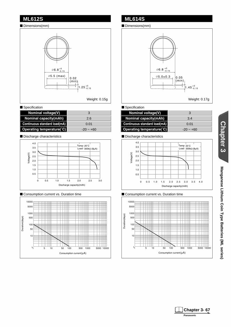
ML612S ML614S Dimensions(mm)
Specifi cation
Discharge characteristics
Dimensions(mm)
Specifi cation
Discharge characteristics
Consumption current vs. Duration time Consumption current vs. Duration time
3
2.6
0.01
-20 ~ +60
3
3.4
0.01
-20 ~ +60
Weight: 0.15g Weight: 0.17g
Man
gan
ese Lith
ium
Co
in T
ype B
atteries (ML
series)
Chapter 3- 68
Ch
apter 3
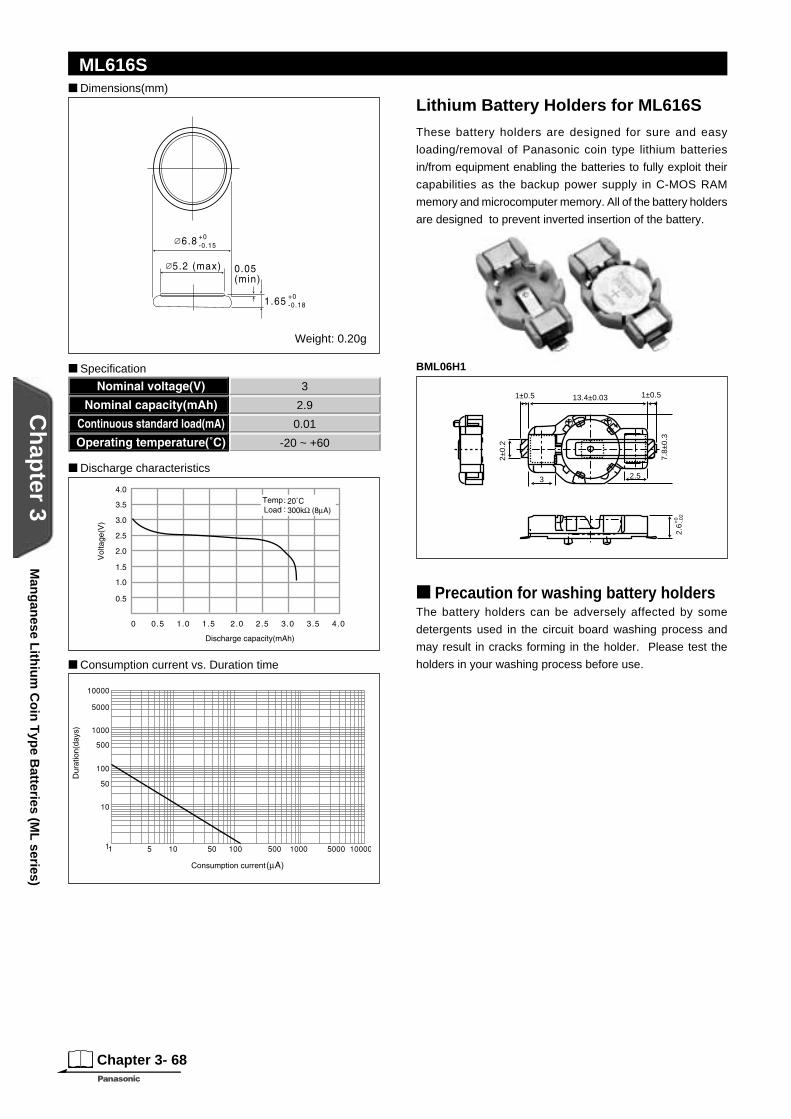
Precaution for washing battery holdersThe battery holders can be adversely affected by some
detergents used in the circuit board washing process and
may result in cracks forming in the holder. Please test the
holders in your washing process before use.
BML06H1
+ +
3 2.5
1±0.5 1±0.513.4±0.03
2±0.
2
7.8±
0.3
2.6
+0
-.02
Dimensions(mm)
Weight: 0.20g
ML616S
Consumption current vs. Duration time
Lithium Battery Holders for ML616S
These battery holders are designed for sure and easy
loading/removal of Panasonic coin type lithium batteries
in/from equipment enabling the batteries to fully exploit their
capabilities as the backup power supply in C-MOS RAM
memory and microcomputer memory. All of the battery holders
are designed to prevent inverted insertion of the battery.
Specifi cation
Discharge characteristics
3
2.9
0.01
-20 ~ +60
Man
gan
ese Lith
ium
Co
in T
ype B
atteries (ML
series)

Chapter 3- 69
Ch
apter 3
ML621S
Consumption current vs. Duration time
ML920S
(ML920S / F9D)
Dimensions (mm)
Specifi cation
Discharge characteristics
Dimensions (mm)
Specifi cation
Discharge characteristics
Charge / discharge characteristics Consumption current vs. Duration time
3
5
0.01
-20 ~ +60
3
11.0
0.03
-20 ~ +60
Weight: 0.30g
Man
gan
ese Lith
ium
Co
in T
ype B
atteries (ML
series)
Chapter 3- 70
Ch
apter 3
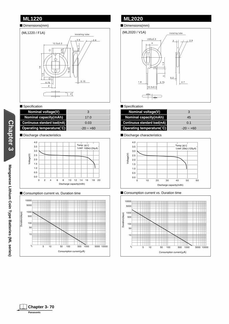
Dimensions(mm)
ML2020 Dimensions(mm)
ML1220
(ML1220 / F1A) (ML2020 / V1A)
Specifi cation
Discharge characteristics
Consumption current vs. Duration time
3
45
0.1
-20 ~ +60
Consumption current vs. Duration time
Specifi cation
Discharge characteristics
3
17.0
0.03
-20 ~ +60
Man
gan
ese Lith
ium
Co
in T
ype B
atteries (ML
series)
Chapter 3- 71
Ch
apter 3
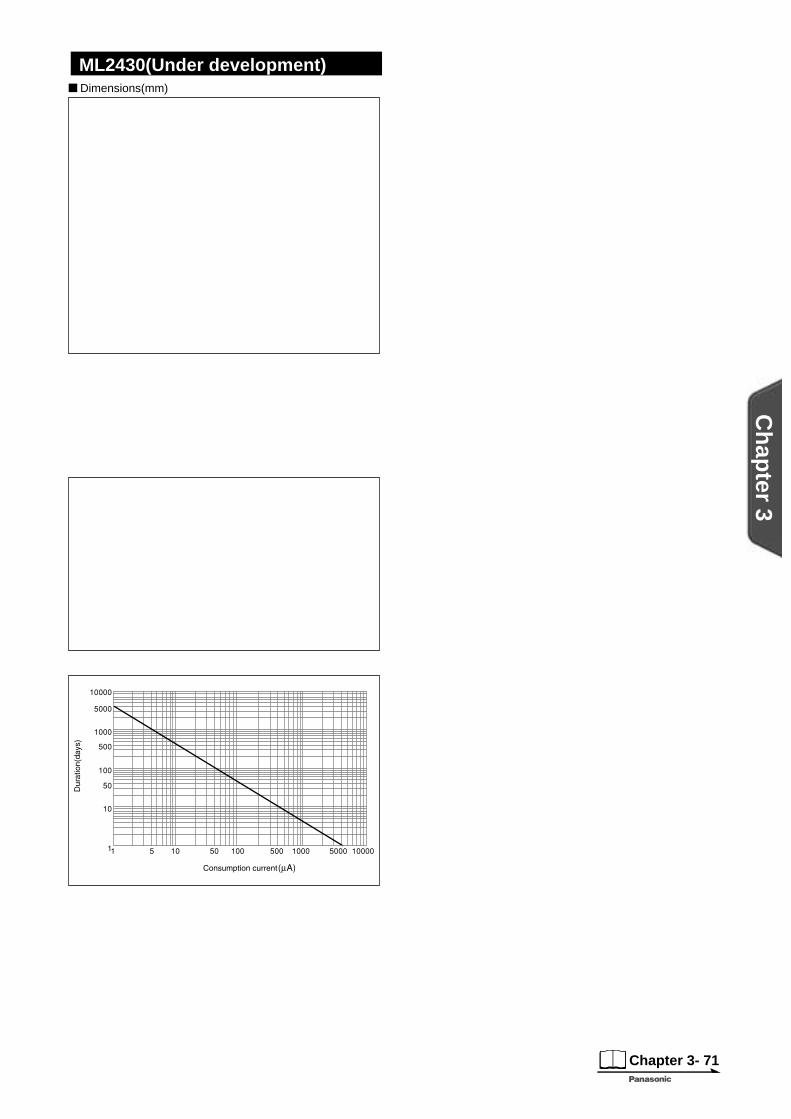
Dimensions(mm)
ML2430(Under development)
Under development
Weight: 4.0g
Specifi cation
Discharge characteristics
Consumption current vs. Duration time
3
120
0.3
-20 ~ +60
Man
gan
ese Lith
ium
Co
in T
ype B
atteries (ML
series)
Chapter 3- 72
Ch
apter 3
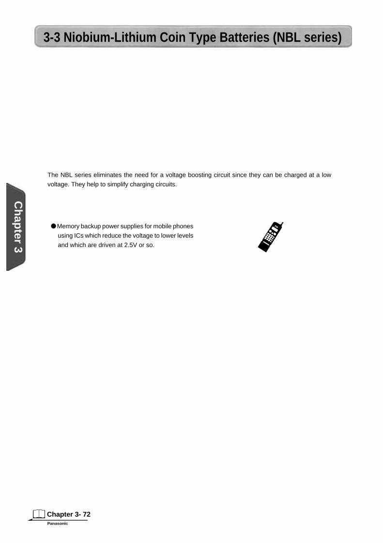
3-3 Niobium-Lithium Coin Type Batteries (NBL series)
The NBL series eliminates the need for a voltage boosting circuit since they can be charged at a low
voltage. They help to simplify charging circuits.
Memory backup power supplies for mobile phones
using ICs which reduce the voltage to lower levels
and which are driven at 2.5V or so.
Features
Applications
General Specifi cations
Model No.
Electrical characteristics (20°C) Dimensions(mm) Weight(g) JIS IEC
Nominal voltage(V) *Nominal capacity(mAh) Continuous drain(mA) Diameter Height
NBL621 2 4 0.01 6.8 2.1 0.25 - -
ChargingConsult Panasonic for charging conditions.
*Nominal capacity shown above is based on standard drain and cut off voltage down to 1.0V at 20°C.
Nio
biu
m L
ithiu
m C
oin
Typ
e Batteries (N
BL
series)
Niobium-Lithium Rechargeable Batteries (NBL series)
Chapter 3- 73
Ch
apter 3
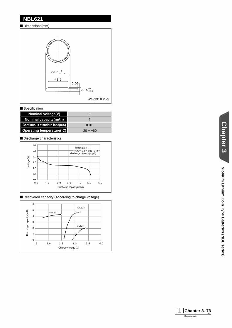
NBL621
Recovered capacity (According to charge voltage)
Dimensions(mm)
Weight: 0.25g
Specifi cation
Discharge characteristics
2
4
0.01
-20 ~ +60
Nio
biu
m L
ithiu
m C
oin
Typ
e Batteries (N
BL
series)
Chapter 3- 74
Ch
apter 3
3-4 Manganese Titanium Lithium Coin Type Batteries (MT series)
These coin-type manganese titanium lithium coin batteries use a lithium-manganese complex oxide
for the positive pole and a special lithium-titanium complex oxide for the negative pole. They provide a
capacity which is more than 10 times that of capacitors of the same size.
Main power supplies in compact products such as
rechargeable watches
Memory backup power supply for pagers, timers, etc.
Consult Panasonic for charging conditions.
Applications
General Specifi cations
Model No. Electrical characteristics (20°C) Dimensions(mm)
Weight(g) JIS IEC Nominal voltage(V) *Nominal capacity(mAh) Continuous drain(mA) Diameter Height
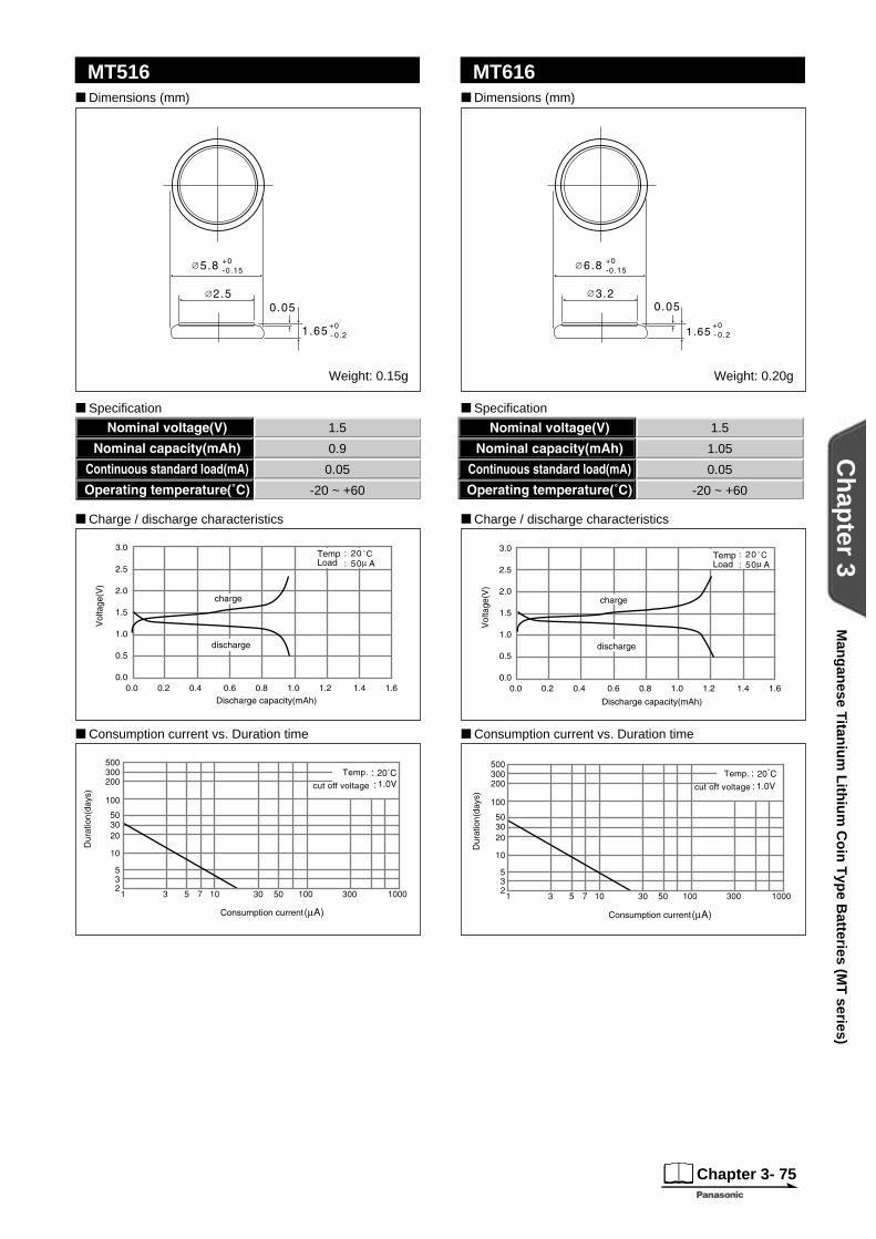
MT516 1.5 0.9 0.05 5.8 1.6 0.15 - -
MT616 1.5 1.05 0.05 6.8 1.6 0.20 - -
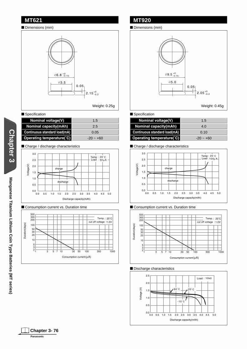
MT621 1.5 2.5 0.05 6.8 2.1 0.25 - -
MT920 1.5 4.0 0.10 9.5 2.0 0.45 - -
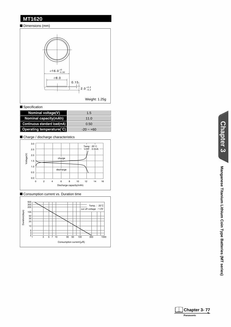
MT1620 1.5 11.0 0.50 16.0 2.0 1.25 - -
*Nominal capacity shown above is based on standard drain and cut off voltage down to 1.0V at 20°C.
Charging
Features
APRIL
Man
gan
ese Titan
ium
Lith
ium
Co
in T
ype B
atteries (MT
series)
Manganese Titanium Lithium Rechargeable Batteries (MT series)
Chapter 3- 75
Ch
apter 3
MT516 MT616
Consumption current vs. Duration time
Charge / discharge characteristics
Consumption current vs. Duration time
Charge / discharge characteristics
Dimensions (mm)
Specifi cation
Dimensions (mm)
Specifi cation
1.5
0.9
0.05
-20 ~ +60
1.5
1.05
0.05
-20 ~ +60
Weight: 0.15g Weight: 0.20g
Man
gan
ese Titan
ium
Lith
ium
Co
in T
ype B
atteries (MT
series)
Chapter 3- 76
Ch
apter 3
MT621 MT920
Consumption current vs. Duration time
Charge / discharge characteristics
Consumption current vs. Duration time
Charge / discharge characteristics
Discharge characteristics
Dimensions (mm)
Weight: 0.45g
Dimensions (mm)
Weight: 0.25g
Specifi cation
1.5
4.0
0.10
-20 ~ +60
Specifi cation
1.5
2.5
0.05
-20 ~ +60
Man
gan
ese Titan
ium
Lith
ium
Co
in T
ype B
atteries (MT
series)
Chapter 3- 77
Ch
apter 3
Dimensions (mm)
Weight: 1.25g
Specifi cation
MT1620
Consumption current vs. Duration time
Charge / discharge characteristics
1.5
11.0
0.50
-20 ~ +60
Man
gan
ese Titan
ium
Lith
ium
Co
in T
ype B
atteries (MT
series)
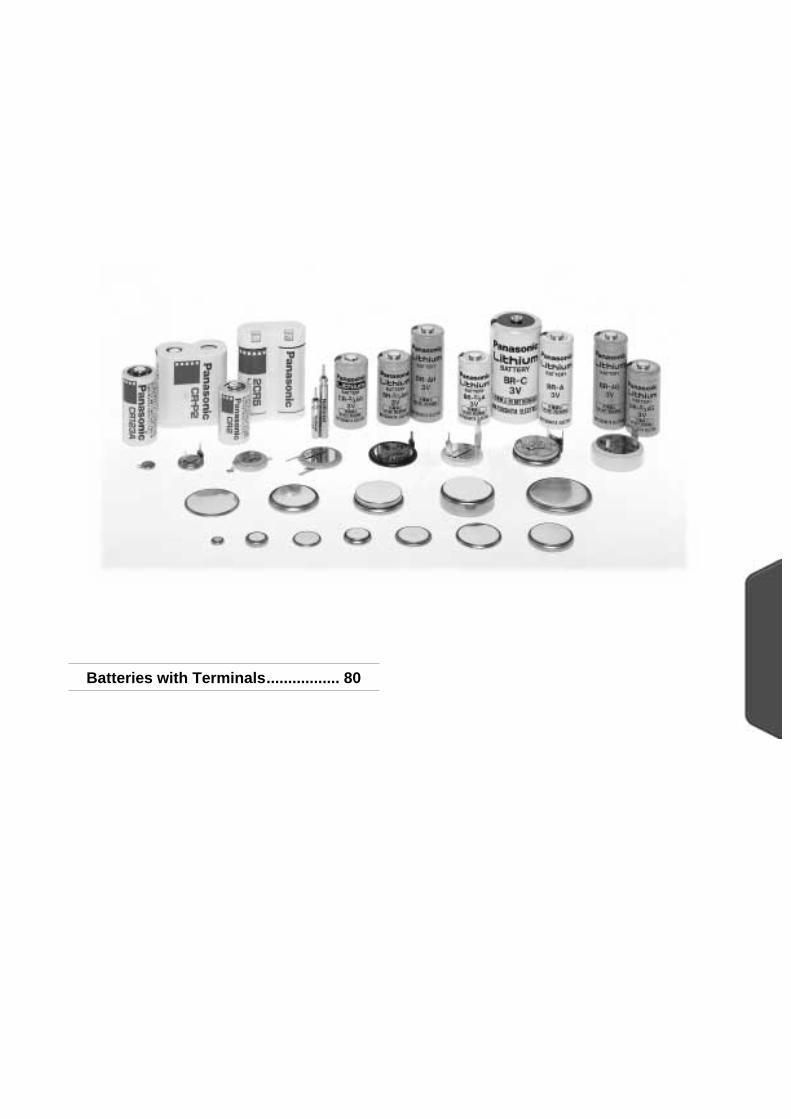
Batteries with Terminals................. 80
Chapter 4
Batteries with Terminals and Soldering Lithium Batteries
INDEXSoldering.......................................... 80
Ch
apter 4
Chapter 4- 80
Ch
apter 4
Batteries with Terminals
Panasonic uses a laser welding method to weld the
terminals onto the batteries so they can be mounted
onto PC boards by soldering. This method has the
effect of boosting the tensile strength accompanying a
welding strength to approximately 100N (approx.10kgf)
compared with 20N to 50N (approx. 2 to 5 kgf) yielded
by the conventional resistance welding method. The
method also more or less cuts in half the individual
variations occurring in the welding. Furthermore, it
enables terminals to be welded onto thin batteries, such
as those with a thickness of 1.6 mm, and it improves
compatibility with many other uses. This highly reliable
terminal soldering method can be used in a wide range
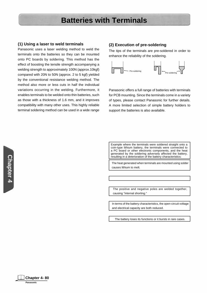
(1) Using a laser to weld terminals (2) Execution of pre-solderingThe tips of the terminals are pre-soldered in order to
enhance the reliability of the soldering.
Panasonic offers a full range of batteries with terminals
for PCB mounting. Since the terminals come in a variety
of types, please contact Panasonic for further details.
A more limited selection of simple battery holders to
support the batteries is also available.
Pre-solderingPre-soldering
Example where the terminals were soldered straight onto a coin-type lithium battery, the terminals were connected to a PC board or other electronic components, and the heat generated by the soldering adversely affected the battery, resulting in a deterioration of the battery characteristics:
The heat generated when terminals are mounted using solder
causes lithium to melt.
The positive and negative poles are welded together,
causing "internal shorting."
In terms of the battery characteristics, the open-circuit voltage
and electrical capacity are both reduced.
The battery loses its functions or it bursts in rare cases.
Highly Reliable Terminal Welding
Complete Line-up
Cautions(1) Using a soldering ironDo not allow the soldering iron to make direct contact
with the bodies of the batteries. Proceed with the
soldering quickly within 5 seconds while maintaining the
iron tip temperature at about 350°C, and do not allow the
temperature of the battery bodies to exceed 85°C.
Soldering
Basic conditions
Dip-soldering bath temperature
Dipping time
Number of dips
260˚C or less
Within 5 sec.
Not more than 2
(2) Automatic dip-soldering bathSoldering with a dip-soldering bath can be used but
do not allow the temperature of the battery bodies to
exceed 85°C. It is important to note, depending on the
temperature conditions inside the dipping device,that
the battery body temperature may rise after dipping
due to the residual heat retained. When a post-dipping
temperature rise is observed, review the temperature
conditions and consider a dipping time reduction or a
way of forcibly cooling the batteries after dipping.
* Consult Panasonic if the battery body temperature will exceed 85°C.
Never use reflow soldering since doing so directly
heats the battery surface to high temperatures,
causing electrolyte leakage, deterioration of battery
characteristics and risking bursting or ignition.
Never Use Refl ow SolderingTerminal Welding
Cathode capLithium(note 1)
Separator(note 2)
Solder
Cathode
(note 1)Metal whose melting point is about 180°C(note 2)Non woven cloth of polypropylene whose melting point is about 165°C
Soldering
of applications, obviating eliminating the need for
reinforcement or other such means.
Batteries w
ith T
ermin
als and
So
lderin
g
The separator melts and becomes perforated.
QS9000 / ISO9001 Approval .......... 82
Transporting Lithium Batteries...... 83
Chapter 5
Standards and Regulations
INDEXSecurity Export Control .................. 83
Ch
apter 5
Chapter 5- 82
Ch
apter 5
Stan
dard
s and
Reg
ulatio
ns
QS9000 / ISO9001 Approval
The Lithium & Micro Battery Division has acquired
certifi cation under ISO9001, the international standard
for quality assurance, for its cylindrical type lithium
batteries and coin-type lithium batteries.
In addition, we have acquired certification under
QS-9000, the quality standard for the automobile
manufacturing industry, for its coin-type lithium primary
batteries.
QS-9000The QS-9000 standard was established by the "Big
Three" U.S. automakers (Daimler-Chrysler, Ford
and GM) on the basis of the ISO9001 international
standard governing quality assurance but with additional
requirements of their own.
A company which has been certifi ed under this standard
can supply highly reliable products by incorporating
into its quality system proven "predictive management"
techniques which are substantiated by numerical data
from a customer satisfaction survey, failure mode and
effects analysis (FMEA), process capability analysis,
measurement systems analysis, etc. which are required
under the standard.
Chapter 5- 83
Ch
apter 5
Stan
dard
s and
Reg
ulatio
ns
The regulation above is an extract of the latest version. See the original for details.U N
ICAO
I A T A
I M O
D O T
(United Nations)
(International Civil Aviation Organization)
(International Air Transport Association)
(International Marin Organization)
(Department Of Transportation) This section of the catalog is quoted by transportation hazards issued by the organizations shown above.
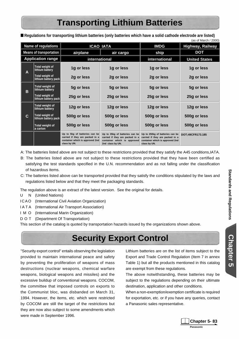
A: The batteries listed above are not subject to these restrictions provided that they satisfy the A45 conditions,IATA.
B: The batteries listed above are not subject to these restrictions provided that they have been certifi ed as
satisfying the test standards specifi ed in the U.N. recommendation and as not falling under the classifi cation
of hazardous items.
C: The batteries listed above can be transported provided that they satisfy the conditions stipulated by the laws and
regulations listed below and that they meet the packaging standards.
Regulations for transporting lithium batteries (only batteries which have a solid cathode electrode are listed)
Transporting Lithium Batteries
Security Export Control"Security export control" entails observing the legislation
provided to maintain international peace and safety
by preventing the proliferation of weapons of mass
destructions (nuclear weapons, chemical warfare
weapons, biological weapons and missiles) and the
excessive buildup of conventional weapons. COCOM,
the committee that imposed controls on exports to
the Communist bloc, was disbanded on March 31,
1994. However, the items, etc. which were restricted
by COCOM are still the target of the restrictions but
they are now also subject to some amendments which
were made in September 1996.
Lithium batteries are on the list of items subject to the
Export and Trade Control Regulation (Item 7 in annex
Table 1) but all the products mentioned in this catalog
are exempt from these regulations.
The above notwithstanding, these batteries may be
subject to the regulations depending on their ultimate
destination, application and other conditions.
When a non-exemption/exemption certifi cate is required
for exportation, etc. or if you have any queries, contact
a Panasonic sales representative.
A
B
C
ICAO IATA
airplane air cargo
international international
ship DOT
United States
IMDG Highway, Railway
1g or less
2g or less
1g or less
2g or less
1g or less
2g or less
1g or less
2g or less
5g or less
25g or less
5g or less
25g or less
5g or less
25g or less
5g or less
25g or less
12g or less
500g or less
500g or less
12g or less
500g or less
500g or less
12g or less
500g or less
500g or less
12g or less
500g or less
500g or less
Up to 5kg of batteries can be carried if they are packed in a container which is approved 2nd class by UN.
Up to 35kg of batteries can be carried if they are packed in a container which is approved 2nd class by UN.
Up to 250kg of batteries can be carried if they are packed in a container which is approved 2nd class by UN.
DOT;49CFR173.185
Name of regulations
Means of transportation
Application range
Total weight of lithium battery
Total weight of lithium battery pack
Total weight of lithium battery
Total weight of lithium battery pack
Total weight of lithium battery
Total weight of a carton
Total weight of lithium battery pack
(as of March / 2000)

Avoiding Hazards............................ 86
Chapter 6
Avoiding Hazards and Preventing Quality Problems
INDEXPreventing Quality Problems ......... 87
Ch
apter 6
Chapter 6- 86
Ch
apter 6
Avo
idin
g H
azards an
d P
reventin
g Q
uality P
rob
lems
Avoiding Hazards
Case Study and Explanation
Ignition2,000 new batteries were taken out from the 20-piece
tray containers and thrown randomly into a cardboard
box where they were stacked on top of one another.
About 30 minutes later, smoke was seen emanating
from the batteries followed by ignition several minutes
after that.
Case study: Ignition of batteries stacked together
To store batteries, place each of the batteries in the sections provided on the designated tray in such a way that
they will not make contact with one another.
Generating Heat21 cylindrical type lithium batteries with tab terminals
were placed in a 20 piece tray--one battery more
than the capacity of the 20-piece tray shown in the
fi gure--two of the batteries were placed together with
their poles reversed. As a result, the tab terminals
came into contact with each other, causing external
shorting, and the temperature of the two batteries rose
dramatically, generating heat and causing the halon
tubes to burst.
Since two batteries were placed in a space (indicated
by ) allocated to one battery, their terminals made
contact with
each other, and
external short-
ing resulted.
an enlargement
Rupture
This particular case involves batteries which were
packed in trays and destined for OEMs. The batteries
were packed in an intermediate package consisting of
10 trays with each tray containing 20 (or 40) batteries,
and the trays were stacked on top of each other. The
intermediate package (of the 10 trays) was opened
at the distribution stage of our operations, and fi ve
of the trays were delivered to one customer. Since
the trays were stored at an angle inside the box, the
batteries fell out of their
positions on the trays
and became stacked
up on the bottom inside
the small box. As a
result, some of the
batteries burst.
Case study: Bursting
of batteries stacked on
top of one another
To store batteries, place each of the batteries in
the sections provided on the designated tray in
such a way that they will not make contact with
one another.
Generating heat and deterioration of capacity
Chapter 6- 87
Ch
apter 6
Avo
idin
g H
azards an
d P
reventin
g Q
uality P
rob
lems
Preventing Quality Problems
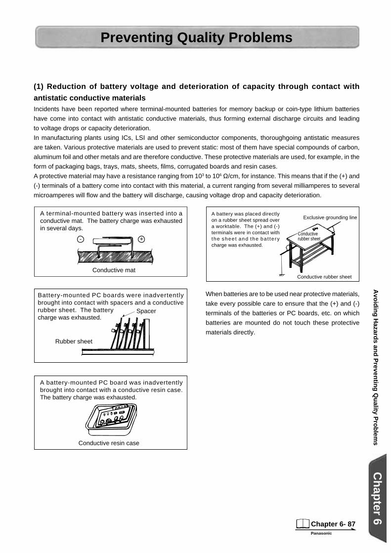
When batteries are to be used near protective materials,
take every possible care to ensure that the (+) and (-)
terminals of the batteries or PC boards, etc. on which
batteries are mounted do not touch these protective
materials directly.
Conductive rubber sheet
Conductiverubber sheet
Exclusive grounding lineA battery was placed directly on a rubber sheet spread over a worktable. The (+) and (-) terminals were in contact with the shee t and the ba t te ry charge was exhausted.
Incidents have been reported where terminal-mounted batteries for memory backup or coin-type lithium batteries
have come into contact with antistatic conductive materials, thus forming external discharge circuits and leading
to voltage drops or capacity deterioration.
In manufacturing plants using ICs, LSI and other semiconductor components, thoroughgoing antistatic measures
are taken. Various protective materials are used to prevent static: most of them have special compounds of carbon,
aluminum foil and other metals and are therefore conductive. These protective materials are used, for example, in the
form of packaging bags, trays, mats, sheets, fi lms, corrugated boards and resin cases.
A protective material may have a resistance ranging from 103 to 106 Ω/cm, for instance. This means that if the (+) and
(-) terminals of a battery come into contact with this material, a current ranging from several milliamperes to several
microamperes will fl ow and the battery will discharge, causing voltage drop and capacity deterioration.
+-
A terminal-mounted battery was inserted into a conductive mat. The battery charge was exhausted in several days.
Conductive mat
Spacer
Battery-mounted PC boards were inadvertently brought into contact with spacers and a conductive rubber sheet. The battery charge was exhausted.
Rubber sheet
Conductive resin case
A battery-mounted PC board was inadvertently brought into contact with a conductive resin case. The battery charge was exhausted.
(1) Reduction of battery voltage and deterioration of capacity through contact with
antistatic conductive materials
Reduction of Battery Voltage and Deterioration of Capacity
Chapter 6- 88
Ch
apter 6
Avo
idin
g H
azards an
d P
reventin
g Q
uality P
rob
lems
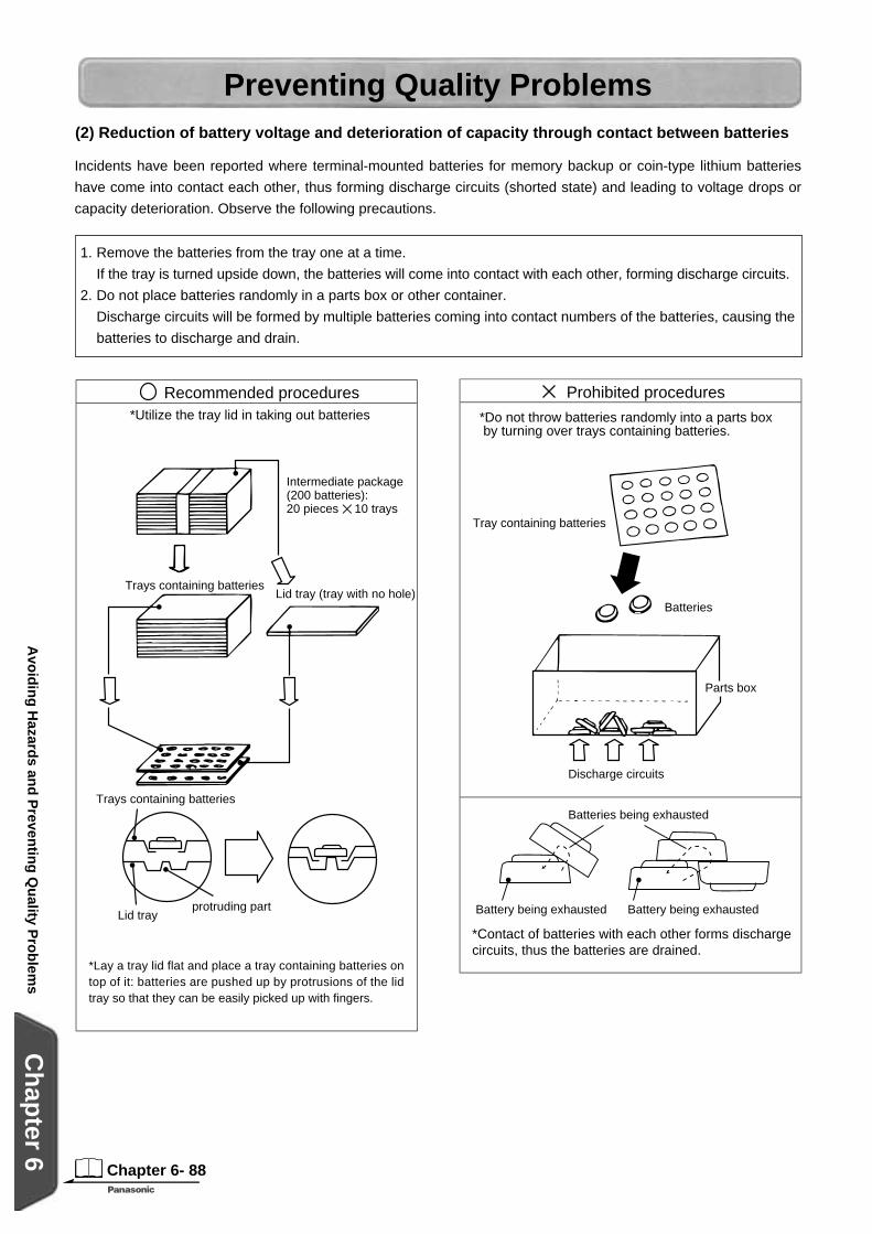
Preventing Quality Problems(2) Reduction of battery voltage and deterioration of capacity through contact between batteries
Incidents have been reported where terminal-mounted batteries for memory backup or coin-type lithium batteries
have come into contact each other, thus forming discharge circuits (shorted state) and leading to voltage drops or
capacity deterioration. Observe the following precautions.
Recommended procedures*Utilize the tray lid in taking out batteries
Intermediate package(200 batteries):20 pieces 10 trays
Lid tray (tray with no hole)Trays containing batteries
Trays containing batteries
Lid trayprotruding part
*Lay a tray lid flat and place a tray containing batteries on top of it: batteries are pushed up by protrusions of the lid tray so that they can be easily picked up with fingers.
1. Remove the batteries from the tray one at a time.
If the tray is turned upside down, the batteries will come into contact with each other, forming discharge circuits.
2. Do not place batteries randomly in a parts box or other container.
Discharge circuits will be formed by multiple batteries coming into contact numbers of the batteries, causing the
batteries to discharge and drain.
Prohibited procedures
*Do not throw batteries randomly into a parts box by turning over trays containing batteries.
Tray containing batteries
Batteries
Parts box
Discharge circuits
Batteries being exhausted
Battery being exhausted Battery being exhausted
*Contact of batteries with each other forms discharge circuits, thus the batteries are drained.

Chapter 6- 89
Ch
apter 6
Avo
idin
g H
azards an
d P
reventin
g Q
uality P
rob
lems
Memory Erasure ProblemsCoin-type lithium batteries are often used as the power
supplies for memory backup in various equipment.
However problems with the erasure of valuable data
in the memory due to improper contact between the
batteries and equipment have been reported.
1. When batteries are to be used continuously for
a prolonged period.
Select tab terminal-mounted batteries, and solder
the tabs to the battery connection terminals of the
equipment. (See Fig. 1)
When batteries need to be replaced, use a
battery holder (see Fig. 2) or battery with lead wire
connectors (see Fig. 3). Battery holders made
by Panasonic (exclusively for the CR2032 and
BR2032, see Fig. 2) are available for use.
2. When batteries need to be replaced in the short
term, select batteries with no terminals or lead
wire connectors.
Use of Y-shaped terminals (2-point contact) for
both the (+) and (-) poles as the shape of the
connection terminals in the equipment helps to
achieve a more stable contact. (See Fig. 4)
The contact pressure of the contacts should be
no less than 2 to 10N (approx. 200 to 1000 gf).
(See Fig. 5)
To prevent momentary contact failure of several
milliseconds in the circuit, the use of a tantalum
capacitor, etc. with a capacitance of several
microfarads is effective. (See Fig. 6)
For the connection terminals of the equipment,
use iron or stainless steel with nickel plating at the
very least. Gold-plating is more suitable when the
contact resistance must be reduced.
Note: Do not touch batteries with bare hands because
perspiration (salt), body oil etc. will increase the
surface resistance which may lead to defective
contact.
Preventing Quality Problems
Fig.1:
Fig. 2
Fig. 3
soldering
<Reference Sample>
Fig. 4
2~10N
Fig. 5:
IC
Fig. 6
excessive load
For Literature and General Product Information:
United Kingdom/IrelandPanasonic Industrial Europe GmbHWilloughby RoadBracknell BerkshireRG12 8FPEnglandTel: +44 1344-853262Fax: +44 1344-853724
ItalyPanasonic Industrial Europe GmbHVia Lucini 1920125 MilanoTel: +39 02-6788-232Fax: +39 02-6788-207
Germany (all other european countries)Panasonic Industrial Europe GmbHWinsbergring 15 22525 HamburgTel: +49 40-85 386-157Fax: +49 40-85 386-160
E-mail and Website for all countries:
www.panasonic-industrial.com/batteries
SpainPanasonic Industrial Europe GmbHAvda. Josep Tarradellas, 20-30, 5°08029 Barcelona - SpainTel: +34 93-494 92 42Fax: +34 93-419 89 31
FrancePanasonic Industrial Europe GmbH 270 avenue du Président Wilson93218 Saint Denis La PlaineTel: +33 1-49 46 44 10Fax: +33 1-49 46 42 20
Panasonic is a registered trademark of Matsushita Electric Co., Ltd.
Batteries - Create A New World
For more details, please contact:
2002. Printed in Germany. This catalogue has been produced using un-chlorinated paper.P


