Reconfigurable Fault Tolerance (RFT) Reconfigurable Fault Tolerance (RFT) for FPGA for FPGA - - based Space Computing based Space Computing Grzegorz Cieslewski Adam Jacobs Chris Conger Alan D. George Brandon Kilpatrick ECE Department, University of Florida
Transcript
Reconfigurable Fault Tolerance (RFT) Reconfigurable Fault Tolerance (RFT) for FPGAfor FPGA--based Space Computingbased Space Computing
Grzegorz CieslewskiAdam JacobsChris Conger
Alan D. GeorgeBrandon Kilpatrick
ECE Department, University of Florida
2
OutlineOutline
IntroductionTaxonomy of FTCurrent FPGA TechniquesRFT ArchitecturePower ConsumptionOverheadReliabilityConclusions
3
Introduction to RFTIntroduction to RFTPROBLEM – Research how to take advantage of reconfigurable nature of FPGAs, enable dynamically-adaptive fault tolerance (FT) in RC systems
Leverage partial reconfiguration (PR) where advantageous
Explore virtual architectures to enable PR and reconfigurablefault tolerance (RFT)
MOTIVATIONS – Why go with fixed/static FT, when performance & reliability can be tuned as needed?
Environmentally-aware & adaptive computing is wave of future
Achieving power savings and/or performance improvement, without sacrificing reliability
CHALLENGES – limitations in concepts and tools,open-ended problem requires innovative solutions
Conventional FT methods largely based upon radiation-hardened components and/or fault masking via chip-level TMR
Highly-custom nature of FPGA architectures in different systemsand apps makes defining a common approach to PR difficult
Satellite orbits, passing throughthe Van Allen radiation belt
Fault Tolerance
4
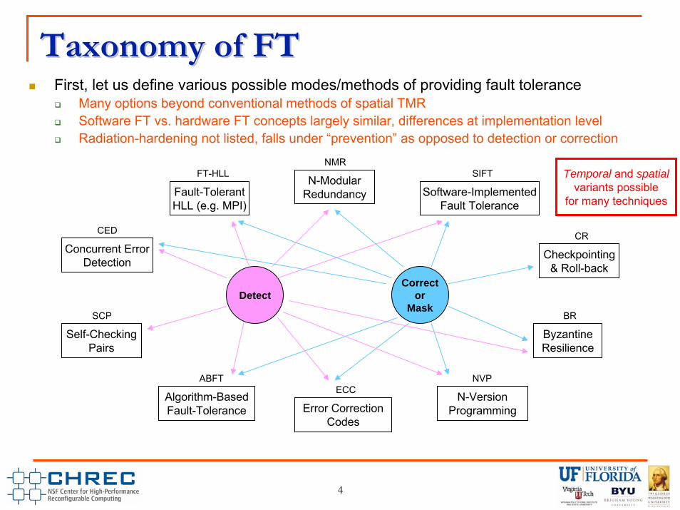
Taxonomy of FTTaxonomy of FTFirst, let us define various possible modes/methods of providing fault tolerance
Many options beyond conventional methods of spatial TMRSoftware FT vs. hardware FT concepts largely similar, differences at implementation levelRadiation-hardening not listed, falls under “prevention” as opposed to detection or correction
DetectCorrect
orMask
Fault-TolerantHLL (e.g. MPI)
FT-HLL
Concurrent ErrorDetection
CED
Self-CheckingPairs
SCP
Algorithm-BasedFault-Tolerance
ABFT
Error CorrectionCodes
ECCN-Version
Programming
NVP
ByzantineResilience
BR
Checkpointing& Roll-back
CR
Software-ImplementedFault Tolerance
SIFTN-Modular
Redundancy
NMRTemporal and spatial
variants possiblefor many techniques
5
Current FPGACurrent FPGA--Based FT TechniquesBased FT TechniquesCurrent FT techniques
ScrubbingConfiguration memory is periodically refreshed to prohibit error accumulation over time
External ReplicationUse of multiple devices – three or more FPGAs connected to external radiation-hardened voter
Internal replication of whole designReplicate user module internally on FPGA
Can use internal or external voterXTMRBYU EDIF Tools
Hybrid ReplicationUses both internal and external replication techniques
Appropriate solution depends upon many factorsExpected operating conditions
Usually worst-case scenario taken into accountPerformance requirements
Placing multiple user modules on same FPGA can decrease overall performance
Power requirementsUsing multiple FPGAs can significantly increase power consumption of whole design
Possible FT Modes for RFT Components Possible FT Modes for RFT Components Coarse-Level Replication
Self-Checking Pair (SCP)Two identical components working in tandem Errors can be detected but recovery has to be taken at a higher level (CPU)
Triple-Modular Redundancy (TMR)Three identical components processing identical dataRecovery can be accomplished by majority voting
Algorithm-Based Fault Tolerance (ABFT)Suitable for certain linear algebra operations and algorithms that can be expressed in using those operationsAugments matrices with extra rows or columns containing weighted checksumsChecksums are preserved through the linear operations
Error-Correcting Codes (ECC)Suitable for buses and memory componentsEmploy extra redundant bits to provide error detection and correction
FT-HLL through source-to-source translationDesigned to provide FT for software running on CPUs Transforms high-level language code into fault-tolerant version by reordering and replicating code fragmentsPlatform- and compiler independent
Matrix C
Column Checksum
Matrix A
Column Checksum
Matrix B
7
Virtual Architecture for RFTVirtual Architecture for RFTNovel concept of adaptablecomponent-level protection (ACP)Common components within VA:
Error Status Register (ESR) for system-level error tracking/handlingSynchronization controller, for state saving and restorationConfiguration controller, two options:
Internal configuration through ICAPExternal configuration controller
Benefits of internal protection:Early error detection and handling = faster recoveryRedundancy can be changed into parallelismRedundancy/parallelism can be traded for powerPR can be leveraged to provide uninterruptedoperation of non-failed components
Challenges of internal protection:Difficult to eliminate single points of failure, may still need higher-level (external) detection and handlingStronger possibility of fault/error going unnoticedSingle-event functional interrupts (SEFI) are concern
A BB
2× parallel, SCP
A
no parallel, TMR
BA DC
4× parallel, single
BLANK
BLANK
no parallel, SCP“sockets” for modules
VA concept diagram
FPGA
8
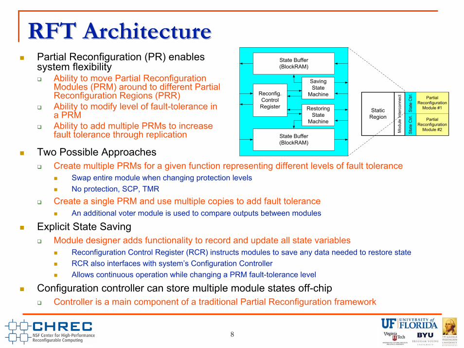
RFT ArchitectureRFT ArchitecturePartial Reconfiguration (PR) enables system flexibility
Ability to move Partial Reconfiguration Modules (PRM) around to different Partial Reconfiguration Regions (PRR)Ability to modify level of fault-tolerance in a PRMAbility to add multiple PRMs to increase fault tolerance through replication
Two Possible ApproachesCreate multiple PRMs for a given function representing different levels of fault tolerance
Swap entire module when changing protection levelsNo protection, SCP, TMR
Create a single PRM and use multiple copies to add fault toleranceAn additional voter module is used to compare outputs between modules
Explicit State SavingModule designer adds functionality to record and update all state variables
Reconfiguration Control Register (RCR) instructs modules to save any data needed to restore stateRCR also interfaces with system’s Configuration ControllerAllows continuous operation while changing a PRM fault-tolerance level
Configuration controller can store multiple module states off-chipController is a main component of a traditional Partial Reconfiguration framework
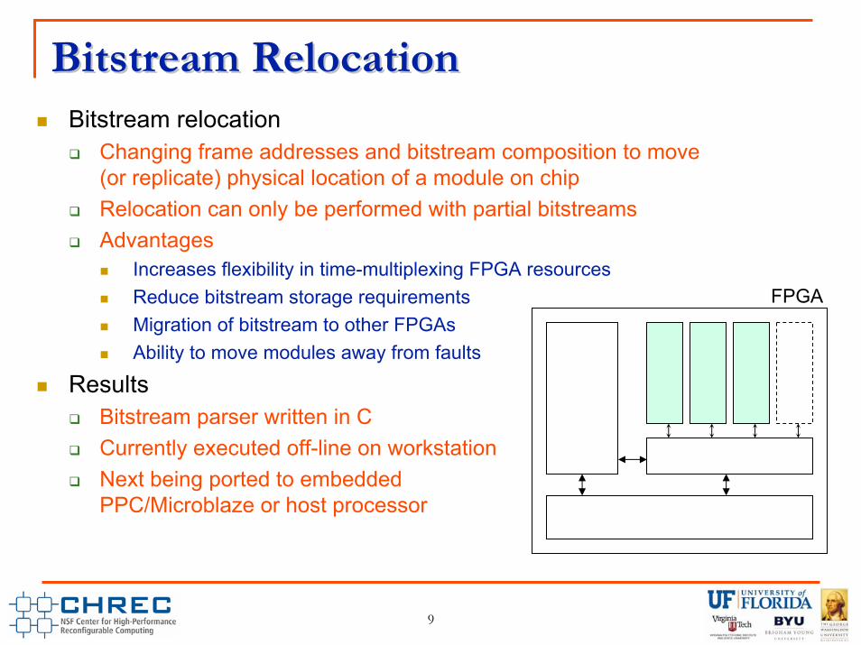
Changing frame addresses and bitstream composition to move(or replicate) physical location of a module on chipRelocation can only be performed with partial bitstreamsAdvantages
Increases flexibility in time-multiplexing FPGA resourcesReduce bitstream storage requirementsMigration of bitstream to other FPGAsAbility to move modules away from faults
ResultsBitstream parser written in CCurrently executed off-line on workstationNext being ported to embeddedPPC/Microblaze or host processor
FPGA
10
0
0.5
1
1.5
2
2.5
3
3.5
Non‐P R 1 P RR 4 P RR
Ratio to Non‐PR
S lice
BRAM
DS P
Overhead of PROverhead of PRIllustrate effect of breaking same design up into different number of PRRsGenerally speaking, required resources increase when going from non-PR to PR
Slices increase ~200% with PRBRAMs increase ~150% with PRDSPs increase ~25% with PR
Take-away pointsLargest price paid by making PR, periodDecomposing PR design into multiple PRRs comes at much less significant cost than non-PR vs. PRFrom FT perspective, physical isolation decreases chances of single fault affecting multiple modulesFrom general PR perspective, more/smaller regions equate to lower reconfiguration overhead
Non‐PR 1 PRR 4 PRR
Slice Registers 11556 43120 45344
Slice LUTs 10196 86240 90688
Slices 3657 10780 11310
BRAMs 23 60 58
DSPs 48 60 58
Single PRM
Multiple PRMs
Situation will vary byapp… these resultsbelieved to be close
to worst-case
11
Power / Overhead AnalysisPower / Overhead Analysis
System‐on‐Chip (V4FX20)Co‐Processor (V5SX95)
None SCP TMR MAX None SCP TMR
6886
6564
13
9
3229021904113178444
8017 21563
16
11033
39
12 44
78
88
32285
117
132DSPs 3 6 176
MAX
Registers 3750 5325 43077
LUTs 3528 5059 42642
BRAMs 7 10 156
Resource UtilizationSoC – ~2.3× resource requirement for MAX over NoneCo-processor – ~3.8× resource requirement for MAX
Power consumption SoC – higher FT increases power 10-30%Co-processor – higher FT increases power 10-50%
Max case uses all four slots of RFT VAe.g. two parallel instances of SCP, 4-way parallel operation“Mode” not relevant to power consumption, simply depends upon how many slots are populated & active
System-on-Chip Power Usage (V4)
0
0.5
1
1.5
2
2.5
NFT SCP TMR MAXFT Mode
Pow
er (W
)
Co-Processor Power Usage (V5)
0
1
2
3
4
5
6
7
NFT SCP TMR MAXFT Mode
Pow
er (W
)
Using spatial TMR & SCP,assuming 25% activity rate
12
Analytical Reliability AnalysisAnalytical Reliability AnalysisAnalytical reliability analysis can help estimate fault susceptibility of proposed designs
Most important parameters are “upset rates”, or lambdas (λ) for each component of RFT; can be approximated based upon respective components resource utilizationOverall system reliability can be expressed as a product of component reliabilities Component-level reliability expression may change depending upon current mode of fault toleranceCurrently, static part of design is not protected by any FT technique
MTTF is a one of important reliability metricsPreliminary results show that possible to significantly increase MTTF using component-level protection in RFTSCP is more susceptible to upsets and functional interrupts but allows for better error detection than case without FT
Conclusions and Future WorkConclusions and Future WorkFault-tolerant computing for space should be more versatile and adaptive than merely RadHard & spatial TMR
Fixed, worst-case designs are extremely limitingHigher power consumptionLarge area overhead
Instead, variety of techniques from FT taxonomy can be employedSCP, ABFT, ECC, etc. can reduce required overhead while maintaining reliability
Adaptive systems (via RFT) can react to environmental changes
Future WorkExtend and refine concept of RFTDevelop proposed RFT architecturesExtend analytical reliability analysis of proposed RFT architecturesVerify and augment analytical reliability analysis using fault injection
14
This research was made possible byNSF I/UCRC Program (Center Grant EEC-0642422)CHREC members (31 industry & govt. partners)Honeywell (prime contractor for NASA’s DM)Xilinx (donated tools)
Questions?
AcknowledgementsAcknowledgements
Please visit CHREC Booth for general info on CHREC mission, projects, schools, and members
Please visit CHREC Booth for general info on CHREC mission, projects, schools, and members