122
Red Hat Enterprise Linux 5 Cluster Administration Configuring and Managing a Red Hat Cluster
| Date post: | 03-Jan-2016 |
| Category: |
Documents |
| Upload: | bridget-powell |
| View: | 64 times |
| Download: | 1 times |
Red Hat Enterprise Linux 5
Cluster AdministrationConfiguring and Managing a Red Hat Cluster

Cluster Administration
Red Hat Enterprise Linux 5 Cluster AdministrationConfiguring and Managing a Red Hat ClusterEdition 5
Copyright © 2010 Red Hat Inc..
The text of and illustrations in this document are licensed by Red Hat under a Creative CommonsAttribution–Share Alike 3.0 Unported license ("CC-BY-SA"). An explanation of CC-BY-SA is availableat http://creativecommons.org/licenses/by-sa/3.0/. In accordance with CC-BY-SA, if you distribute thisdocument or an adaptation of it, you must provide the URL for the original version.
Red Hat, as the licensor of this document, waives the right to enforce, and agrees not to assert,Section 4d of CC-BY-SA to the fullest extent permitted by applicable law.
Red Hat, Red Hat Enterprise Linux, the Shadowman logo, JBoss, MetaMatrix, Fedora, the InfinityLogo, and RHCE are trademarks of Red Hat, Inc., registered in the United States and other countries.
Linux® is the registered trademark of Linus Torvalds in the United States and other countries.
Java® is a registered trademark of Oracle and/or its affiliates.
XFS® is a trademark of Silicon Graphics International Corp. or its subsidiaries in the United Statesand/or other countries.
MySQL® is a registered trademark of MySQL AB in the United States, the European Union and othercountries.
All other trademarks are the property of their respective owners.
1801 Varsity Drive Raleigh, NC 27606-2072 USA Phone: +1 919 754 3700 Phone: 888 733 4281 Fax: +1 919 754 3701
Configuring and Managing a Red Hat Cluster describes the configuration and management ofRed Hat cluster systems for Red Hat Enterprise Linux 5. It does not include information about RedHat Linux Virtual Servers (LVS). Information about installing and configuring LVS is in a separatedocument.
iii
Introduction v1. Document Conventions ................................................................................................... vi
1.1. Typographic Conventions ..................................................................................... vi1.2. Pull-quote Conventions ........................................................................................ vii1.3. Notes and Warnings ........................................................................................... viii
2. Feedback ..................................................................................................................... viii
1. Red Hat Cluster Configuration and Management Overview 11.1. Configuration Basics ..................................................................................................... 1
1.1.1. Setting Up Hardware ......................................................................................... 11.1.2. Installing Red Hat Cluster software ..................................................................... 21.1.3. Configuring Red Hat Cluster Software ................................................................ 2
1.2. Conga ......................................................................................................................... 41.3. system-config-cluster Cluster Administration GUI ................................................. 6
1.3.1. Cluster Configuration Tool .............................................................................. 61.3.2. Cluster Status Tool .......................................................................................... 8
1.4. Command Line Administration Tools .............................................................................. 9
2. Before Configuring a Red Hat Cluster 112.1. General Configuration Considerations .......................................................................... 112.2. Compatible Hardware ................................................................................................. 122.3. Enabling IP Ports ....................................................................................................... 12
2.3.1. Enabling IP Ports on Cluster Nodes .................................................................. 122.3.2. Enabling IP Ports on Computers That Run luci ................................................. 13
2.4. Configuring ACPI For Use with Integrated Fence Devices ............................................. 132.4.1. Disabling ACPI Soft-Off with chkconfig Management ...................................... 152.4.2. Disabling ACPI Soft-Off with the BIOS .............................................................. 152.4.3. Disabling ACPI Completely in the grub.conf File ............................................ 17
2.5. Considerations for Configuring HA Services ................................................................. 182.6. Configuring max_luns ................................................................................................. 202.7. Considerations for Using Quorum Disk ........................................................................ 212.8. Red Hat Cluster Suite and SELinux ............................................................................. 222.9. Multicast Addresses ................................................................................................... 222.10. Considerations for Using Conga ............................................................................... 23
3. Configuring Red Hat Cluster With Conga 253.1. Configuration Tasks .................................................................................................... 253.2. Starting luci and ricci ................................................................................................ 253.3. Creating A Cluster ...................................................................................................... 273.4. Global Cluster Properties ............................................................................................ 273.5. Configuring Fence Devices ......................................................................................... 30
3.5.1. Creating a Shared Fence Device ...................................................................... 313.5.2. Modifying or Deleting a Fence Device ............................................................... 33
3.6. Configuring Cluster Members ...................................................................................... 333.6.1. Initially Configuring Members ............................................................................ 343.6.2. Adding a Member to a Running Cluster ............................................................ 343.6.3. Deleting a Member from a Cluster .................................................................... 35
3.7. Configuring a Failover Domain .................................................................................... 363.7.1. Adding a Failover Domain ................................................................................ 373.7.2. Modifying a Failover Domain ............................................................................ 38
3.8. Adding Cluster Resources .......................................................................................... 393.9. Adding a Cluster Service to the Cluster ....................................................................... 393.10. Configuring Cluster Storage ...................................................................................... 41
4. Managing Red Hat Cluster With Conga 434.1. Starting, Stopping, and Deleting Clusters ..................................................................... 43
Cluster Administration
iv
4.2. Managing Cluster Nodes ............................................................................................ 444.3. Managing High-Availability Services ............................................................................ 454.4. Diagnosing and Correcting Problems in a Cluster ......................................................... 46
5. Configuring Red Hat Cluster With system-config-cluster 475.1. Configuration Tasks .................................................................................................... 475.2. Starting the Cluster Configuration Tool ..................................................................... 485.3. Configuring Cluster Properties ..................................................................................... 535.4. Configuring Fence Devices ......................................................................................... 545.5. Adding and Deleting Members .................................................................................... 54
5.5.1. Adding a Member to a Cluster .......................................................................... 555.5.2. Adding a Member to a Running Cluster ............................................................ 565.5.3. Deleting a Member from a Cluster .................................................................... 58
5.6. Configuring a Failover Domain .................................................................................... 595.6.1. Adding a Failover Domain ................................................................................ 605.6.2. Removing a Failover Domain ........................................................................... 625.6.3. Removing a Member from a Failover Domain .................................................... 63
5.7. Adding Cluster Resources .......................................................................................... 635.8. Adding a Cluster Service to the Cluster ....................................................................... 645.9. Propagating The Configuration File: New Cluster ......................................................... 675.10. Starting the Cluster Software ..................................................................................... 67
6. Managing Red Hat Cluster With system-config-cluster 696.1. Starting and Stopping the Cluster Software .................................................................. 696.2. Managing High-Availability Services ............................................................................ 696.3. Modifying the Cluster Configuration ............................................................................. 716.4. Backing Up and Restoring the Cluster Database .......................................................... 726.5. Disabling the Cluster Software .................................................................................... 736.6. Diagnosing and Correcting Problems in a Cluster ......................................................... 74
A. Example of Setting Up Apache HTTP Server 75A.1. Apache HTTP Server Setup Overview ........................................................................ 75A.2. Configuring Shared Storage ........................................................................................ 75A.3. Installing and Configuring the Apache HTTP Server ..................................................... 76
B. Fence Device Parameters 79
C. HA Resource Parameters 87
D. HA Resource Behavior 95D.1. Parent, Child, and Sibling Relationships Among Resources .......................................... 96D.2. Sibling Start Ordering and Resource Child Ordering ..................................................... 96
D.2.1. Typed Child Resource Start and Stop Ordering ................................................. 97D.2.2. Non-typed Child Resource Start and Stop Ordering ........................................... 99
D.3. Inheritance, the <resources> Block, and Reusing Resources ...................................... 100D.4. Failure Recovery and Independent Subtrees ............................................................. 101D.5. Debugging and Testing Services and Resource Ordering ............................................ 102
E. Upgrading A Red Hat Cluster from RHEL 4 to RHEL 5 105
F. Revision History 109
Index 111
v
IntroductionThis document provides information about installing, configuring and managing Red Hat Clustercomponents. Red Hat Cluster components are part of Red Hat Cluster Suite and allow you to connecta group of computers (called nodes or members) to work together as a cluster. This documentdoes not include information about installing, configuring, and managing Linux Virtual Server (LVS)software. Information about that is in a separate document.
The audience of this document should have advanced working knowledge of Red Hat Enterprise Linuxand understand the concepts of clusters, storage, and server computing.
This document is organized as follows:
• Chapter 1, Red Hat Cluster Configuration and Management Overview
• Chapter 2, Before Configuring a Red Hat Cluster
• Chapter 3, Configuring Red Hat Cluster With Conga
• Chapter 4, Managing Red Hat Cluster With Conga
• Chapter 5, Configuring Red Hat Cluster With system-config-cluster
• Chapter 6, Managing Red Hat Cluster With system-config-cluster
• Appendix A, Example of Setting Up Apache HTTP Server
• Appendix B, Fence Device Parameters
• Appendix C, HA Resource Parameters
• Appendix D, HA Resource Behavior
• Appendix E, Upgrading A Red Hat Cluster from RHEL 4 to RHEL 5
• Appendix F, Revision History
For more information about Red Hat Enterprise Linux 5, refer to the following resources:
• Red Hat Enterprise Linux Installation Guide — Provides information regarding installation of RedHat Enterprise Linux 5.
• Red Hat Enterprise Linux Deployment Guide — Provides information regarding the deployment,configuration and administration of Red Hat Enterprise Linux 5.
For more information about Red Hat Cluster Suite for Red Hat Enterprise Linux 5, refer to the followingresources:
• Red Hat Cluster Suite Overview — Provides a high level overview of the Red Hat Cluster Suite.
• Logical Volume Manager Administration — Provides a description of the Logical Volume Manager(LVM), including information on running LVM in a clustered environment.
• Global File System: Configuration and Administration — Provides information about installing,configuring, and maintaining Red Hat GFS (Red Hat Global File System).
• Global File System 2: Configuration and Administration — Provides information about installing,configuring, and maintaining Red Hat GFS2 (Red Hat Global File System 2).
Introduction
vi
• Using Device-Mapper Multipath — Provides information about using the Device-Mapper Multipathfeature of Red Hat Enterprise Linux 5.
• Using GNBD with Global File System — Provides an overview on using Global Network BlockDevice (GNBD) with Red Hat GFS.
• Linux Virtual Server Administration — Provides information on configuring high-performancesystems and services with the Linux Virtual Server (LVS).
• Red Hat Cluster Suite Release Notes — Provides information about the current release of Red HatCluster Suite.
Red Hat Cluster Suite documentation and other Red Hat documents are available in HTML,PDF, and RPM versions on the Red Hat Enterprise Linux Documentation CD and online at http://www.redhat.com/docs/.
1. Document ConventionsThis manual uses several conventions to highlight certain words and phrases and draw attention tospecific pieces of information.
In PDF and paper editions, this manual uses typefaces drawn from the Liberation Fonts1 set. TheLiberation Fonts set is also used in HTML editions if the set is installed on your system. If not,alternative but equivalent typefaces are displayed. Note: Red Hat Enterprise Linux 5 and later includesthe Liberation Fonts set by default.
1.1. Typographic ConventionsFour typographic conventions are used to call attention to specific words and phrases. Theseconventions, and the circumstances they apply to, are as follows.
Mono-spaced Bold
Used to highlight system input, including shell commands, file names and paths. Also used to highlightkeycaps and key combinations. For example:
To see the contents of the file my_next_bestselling_novel in your currentworking directory, enter the cat my_next_bestselling_novel command at theshell prompt and press Enter to execute the command.
The above includes a file name, a shell command and a keycap, all presented in mono-spaced boldand all distinguishable thanks to context.
Key combinations can be distinguished from keycaps by the hyphen connecting each part of a keycombination. For example:
Press Enter to execute the command.
Press Ctrl+Alt+F2 to switch to the first virtual terminal. Press Ctrl+Alt+F1 toreturn to your X-Windows session.
The first paragraph highlights the particular keycap to press. The second highlights two keycombinations (each a set of three keycaps with each set pressed simultaneously).
1 https://fedorahosted.org/liberation-fonts/
Pull-quote Conventions
vii
If source code is discussed, class names, methods, functions, variable names and returned valuesmentioned within a paragraph will be presented as above, in mono-spaced bold. For example:
File-related classes include filesystem for file systems, file for files, and dir fordirectories. Each class has its own associated set of permissions.
Proportional Bold
This denotes words or phrases encountered on a system, including application names; dialog box text;labeled buttons; check-box and radio button labels; menu titles and sub-menu titles. For example:
Choose System → Preferences → Mouse from the main menu bar to launch MousePreferences. In the Buttons tab, click the Left-handed mouse check box and clickClose to switch the primary mouse button from the left to the right (making the mousesuitable for use in the left hand).
To insert a special character into a gedit file, choose Applications → Accessories→ Character Map from the main menu bar. Next, choose Search → Find… from theCharacter Map menu bar, type the name of the character in the Search field and clickNext. The character you sought will be highlighted in the Character Table. Double-click this highlighted character to place it in the Text to copy field and then click the
Copy button. Now switch back to your document and choose Edit → Paste from thegedit menu bar.
The above text includes application names; system-wide menu names and items; application-specificmenu names; and buttons and text found within a GUI interface, all presented in proportional bold andall distinguishable by context.
Mono-spaced Bold Italic or Proportional Bold Italic
Whether mono-spaced bold or proportional bold, the addition of italics indicates replaceable orvariable text. Italics denotes text you do not input literally or displayed text that changes depending oncircumstance. For example:
To connect to a remote machine using ssh, type ssh [email protected] ata shell prompt. If the remote machine is example.com and your username on thatmachine is john, type ssh [email protected].
The mount -o remount file-system command remounts the named filesystem. For example, to remount the /home file system, the command is mount -oremount /home.
To see the version of a currently installed package, use the rpm -q packagecommand. It will return a result as follows: package-version-release.
Note the words in bold italics above — username, domain.name, file-system, package, version andrelease. Each word is a placeholder, either for text you enter when issuing a command or for textdisplayed by the system.
Aside from standard usage for presenting the title of a work, italics denotes the first use of a new andimportant term. For example:
Publican is a DocBook publishing system.
1.2. Pull-quote ConventionsTerminal output and source code listings are set off visually from the surrounding text.
Introduction
viii
Output sent to a terminal is set in mono-spaced roman and presented thus:
books Desktop documentation drafts mss photos stuff svnbooks_tests Desktop1 downloads images notes scripts svgs
Source-code listings are also set in mono-spaced roman but add syntax highlighting as follows:
package org.jboss.book.jca.ex1;
import javax.naming.InitialContext;
public class ExClient{ public static void main(String args[]) throws Exception { InitialContext iniCtx = new InitialContext(); Object ref = iniCtx.lookup("EchoBean"); EchoHome home = (EchoHome) ref; Echo echo = home.create();
System.out.println("Created Echo");
System.out.println("Echo.echo('Hello') = " + echo.echo("Hello")); }}
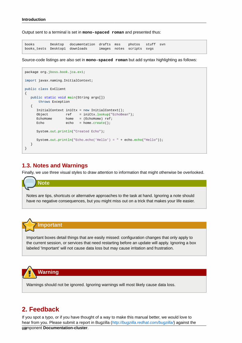
1.3. Notes and WarningsFinally, we use three visual styles to draw attention to information that might otherwise be overlooked.
Note
Notes are tips, shortcuts or alternative approaches to the task at hand. Ignoring a note shouldhave no negative consequences, but you might miss out on a trick that makes your life easier.
Important
Important boxes detail things that are easily missed: configuration changes that only apply tothe current session, or services that need restarting before an update will apply. Ignoring a boxlabeled 'Important' will not cause data loss but may cause irritation and frustration.
Warning
Warnings should not be ignored. Ignoring warnings will most likely cause data loss.
2. FeedbackIf you spot a typo, or if you have thought of a way to make this manual better, we would love tohear from you. Please submit a report in Bugzilla (http://bugzilla.redhat.com/bugzilla/) against thecomponent Documentation-cluster.

Feedback
ix
Be sure to mention the manual identifier:
Cluster_Administration(EN)-5 (2010-12-23T15:52)
By mentioning this manual's identifier, we know exactly which version of the guide you have.
If you have a suggestion for improving the documentation, try to be as specific as possible. If you havefound an error, please include the section number and some of the surrounding text so we can find iteasily.

x
Chapter 1.
1
Red Hat Cluster Configuration andManagement OverviewRed Hat Cluster allows you to connect a group of computers (called nodes or members) to worktogether as a cluster. It provides a wide variety of ways to configure hardware and software to suityour clustering needs (for example, a cluster for sharing files on a GFS file system or a cluster withhigh-availability service failover). This book provides information about how to use configuration toolsto configure your cluster and provides considerations to take into account before deploying a RedHat Cluster. To ensure that your deployment of Red Hat Cluster fully meets your needs and can besupported, consult with an authorized Red Hat representative before you deploy it.
1.1. Configuration BasicsTo set up a cluster, you must connect the nodes to certain cluster hardware and configure thenodes into the cluster environment. This chapter provides an overview of cluster configuration andmanagement, and tools available for configuring and managing a Red Hat Cluster.
Configuring and managing a Red Hat Cluster consists of the following basic steps:
1. Setting up hardware. Refer to Section 1.1.1, “Setting Up Hardware”.
2. Installing Red Hat Cluster software. Refer to Section 1.1.2, “Installing Red Hat Cluster software”.
3. Configuring Red Hat Cluster Software. Refer to Section 1.1.3, “Configuring Red Hat ClusterSoftware”.
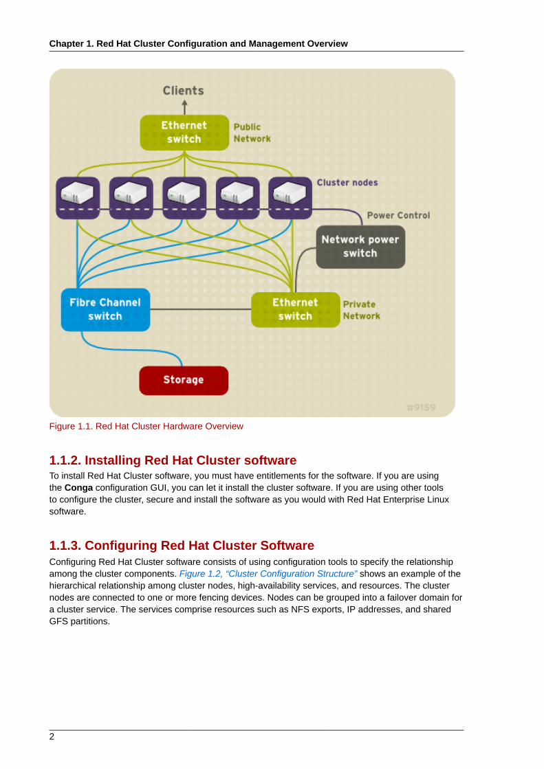
1.1.1. Setting Up HardwareSetting up hardware consists of connecting cluster nodes to other hardware required to run a RedHat Cluster. The amount and type of hardware varies according to the purpose and availabilityrequirements of the cluster. Typically, an enterprise-level cluster requires the following type ofhardware (refer to Figure 1.1, “Red Hat Cluster Hardware Overview”).For considerations abouthardware and other cluster configuration concerns, refer to "Before Configuring a Red Hat Cluster" orcheck with an authorized Red Hat representative.
• Cluster nodes — Computers that are capable of running Red Hat Enterprise Linux 5 software, withat least 1GB of RAM. The maximum number of nodes supported in a Red Hat Cluster is 16.
• Ethernet switch or hub for public network — This is required for client access to the cluster.
• Ethernet switch or hub for private network — This is required for communication among the clusternodes and other cluster hardware such as network power switches and Fibre Channel switches.
• Network power switch — A network power switch is recommended to perform fencing in anenterprise-level cluster.
• Fibre Channel switch — A Fibre Channel switch provides access to Fibre Channel storage. Otheroptions are available for storage according to the type of storage interface; for example, iSCSI orGNBD. A Fibre Channel switch can be configured to perform fencing.
• Storage — Some type of storage is required for a cluster. The type required depends on thepurpose of the cluster.
Chapter 1. Red Hat Cluster Configuration and Management Overview
2
Figure 1.1. Red Hat Cluster Hardware Overview
1.1.2. Installing Red Hat Cluster softwareTo install Red Hat Cluster software, you must have entitlements for the software. If you are usingthe Conga configuration GUI, you can let it install the cluster software. If you are using other toolsto configure the cluster, secure and install the software as you would with Red Hat Enterprise Linuxsoftware.
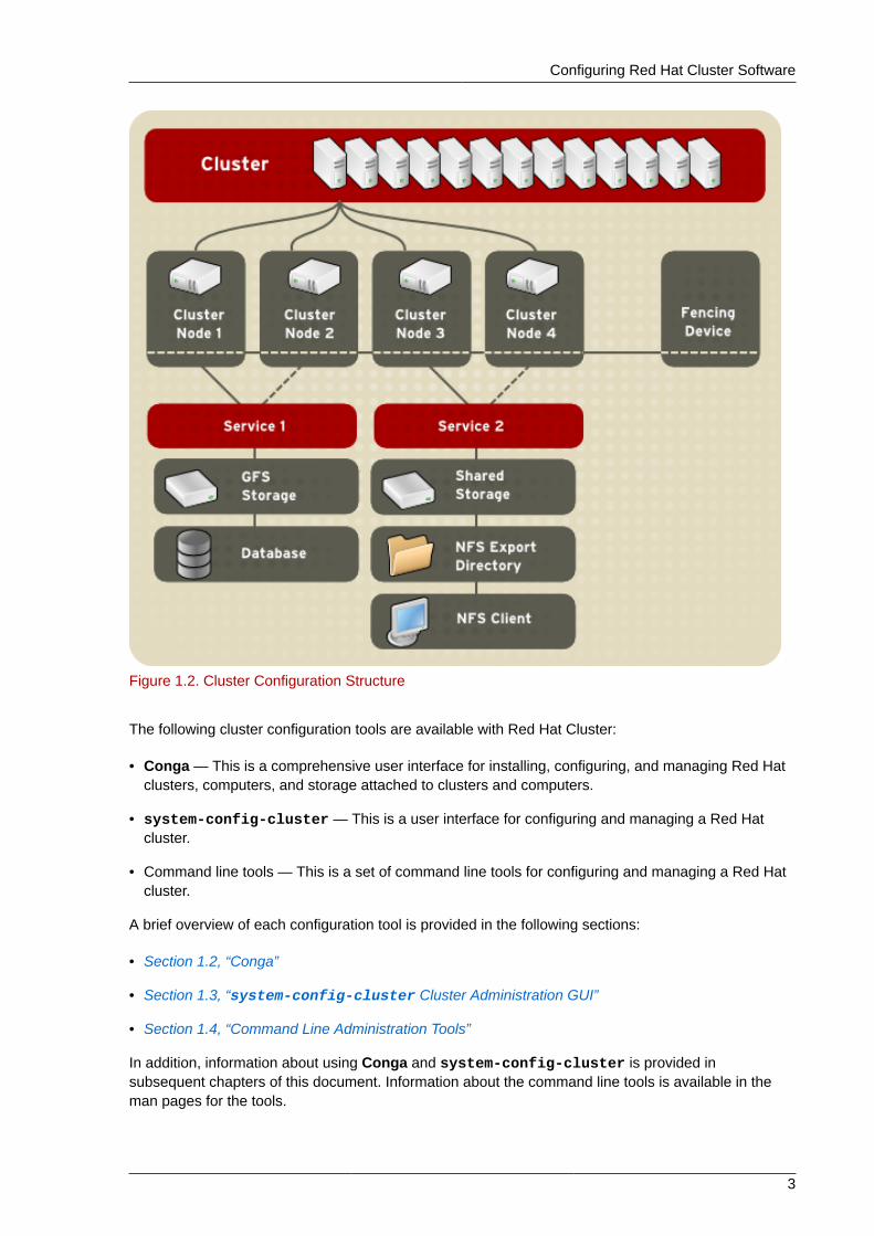
1.1.3. Configuring Red Hat Cluster SoftwareConfiguring Red Hat Cluster software consists of using configuration tools to specify the relationshipamong the cluster components. Figure 1.2, “Cluster Configuration Structure” shows an example of thehierarchical relationship among cluster nodes, high-availability services, and resources. The clusternodes are connected to one or more fencing devices. Nodes can be grouped into a failover domain fora cluster service. The services comprise resources such as NFS exports, IP addresses, and sharedGFS partitions.
Configuring Red Hat Cluster Software
3
Figure 1.2. Cluster Configuration Structure
The following cluster configuration tools are available with Red Hat Cluster:
• Conga — This is a comprehensive user interface for installing, configuring, and managing Red Hatclusters, computers, and storage attached to clusters and computers.
• system-config-cluster — This is a user interface for configuring and managing a Red Hatcluster.
• Command line tools — This is a set of command line tools for configuring and managing a Red Hatcluster.
A brief overview of each configuration tool is provided in the following sections:
• Section 1.2, “Conga”
• Section 1.3, “system-config-cluster Cluster Administration GUI”
• Section 1.4, “Command Line Administration Tools”
In addition, information about using Conga and system-config-cluster is provided insubsequent chapters of this document. Information about the command line tools is available in theman pages for the tools.
Chapter 1. Red Hat Cluster Configuration and Management Overview
4
1.2. CongaConga is an integrated set of software components that provides centralized configuration andmanagement of Red Hat clusters and storage. Conga provides the following major features:
• One Web interface for managing cluster and storage
• Automated Deployment of Cluster Data and Supporting Packages
• Easy Integration with Existing Clusters
• No Need to Re-Authenticate
• Integration of Cluster Status and Logs
• Fine-Grained Control over User Permissions
The primary components in Conga are luci and ricci, which are separately installable. luci is a serverthat runs on one computer and communicates with multiple clusters and computers via ricci. ricci isan agent that runs on each computer (either a cluster member or a standalone computer) managed byConga.
luci is accessible through a Web browser and provides three major functions that are accessiblethrough the following tabs:
• homebase — Provides tools for adding and deleting computers, adding and deleting users, andconfiguring user privileges. Only a system administrator is allowed to access this tab.
• cluster — Provides tools for creating and configuring clusters. Each instance of luci lists clustersthat have been set up with that luci. A system administrator can administer all clusters listed on thistab. Other users can administer only clusters that the user has permission to manage (granted by anadministrator).
• storage — Provides tools for remote administration of storage. With the tools on this tab, you canmanage storage on computers whether they belong to a cluster or not.
To administer a cluster or storage, an administrator adds (or registers) a cluster or a computer to aluci server. When a cluster or a computer is registered with luci, the FQDN hostname or IP address ofeach computer is stored in a luci database.
You can populate the database of one luci instance from another luciinstance. That capabilityprovides a means of replicating a luci server instance and provides an efficient upgrade and testingpath. When you install an instance of luci, its database is empty. However, you can import part or all ofa luci database from an existing luci server when deploying a new luci server.
Each luci instance has one user at initial installation — admin. Only the admin user may add systemsto a luci server. Also, the admin user can create additional user accounts and determine which usersare allowed to access clusters and computers registered in the luci database. It is possible to importusers as a batch operation in a new luci server, just as it is possible to import clusters and computers.
When a computer is added to a luci server to be administered, authentication is done once. Noauthentication is necessary from then on (unless the certificate used is revoked by a CA). After that,you can remotely configure and manage clusters and storage through the luci user interface. luci andricci communicate with each other via XML.
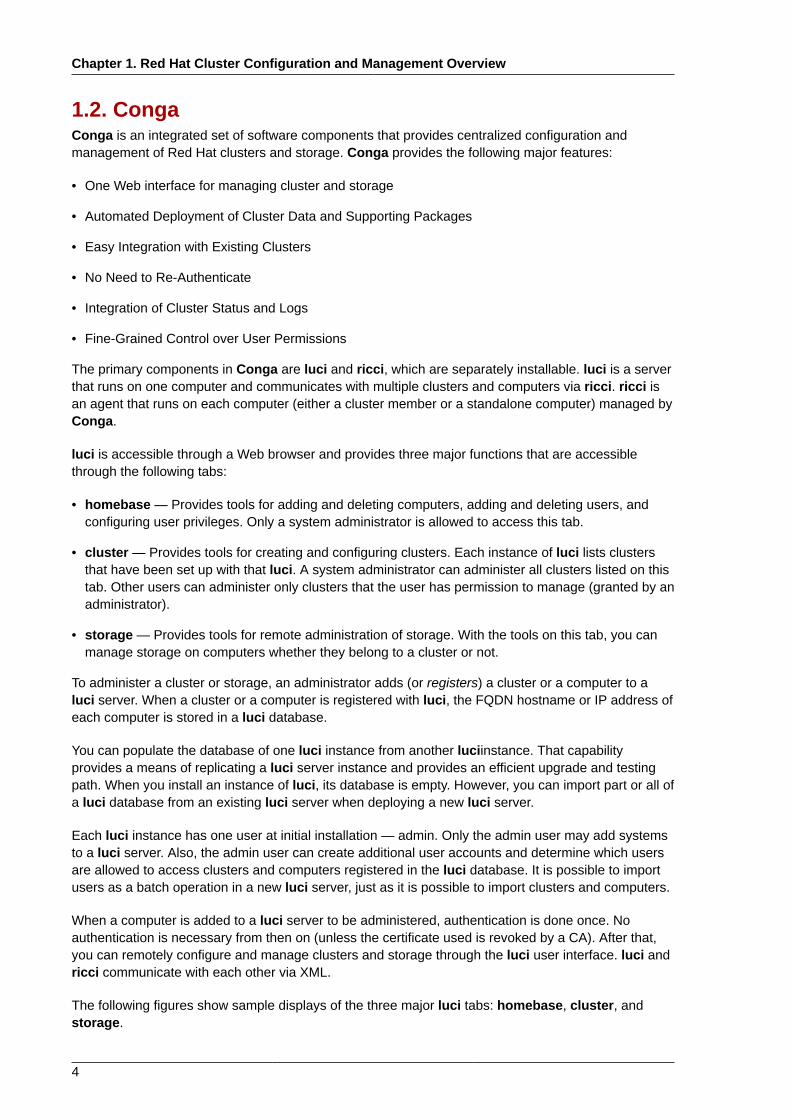
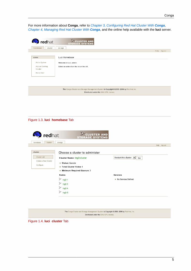
The following figures show sample displays of the three major luci tabs: homebase, cluster, andstorage.
Conga
5
For more information about Conga, refer to Chapter 3, Configuring Red Hat Cluster With Conga,Chapter 4, Managing Red Hat Cluster With Conga, and the online help available with the luci server.
Figure 1.3. luci homebase Tab
Figure 1.4. luci cluster Tab
Chapter 1. Red Hat Cluster Configuration and Management Overview
6
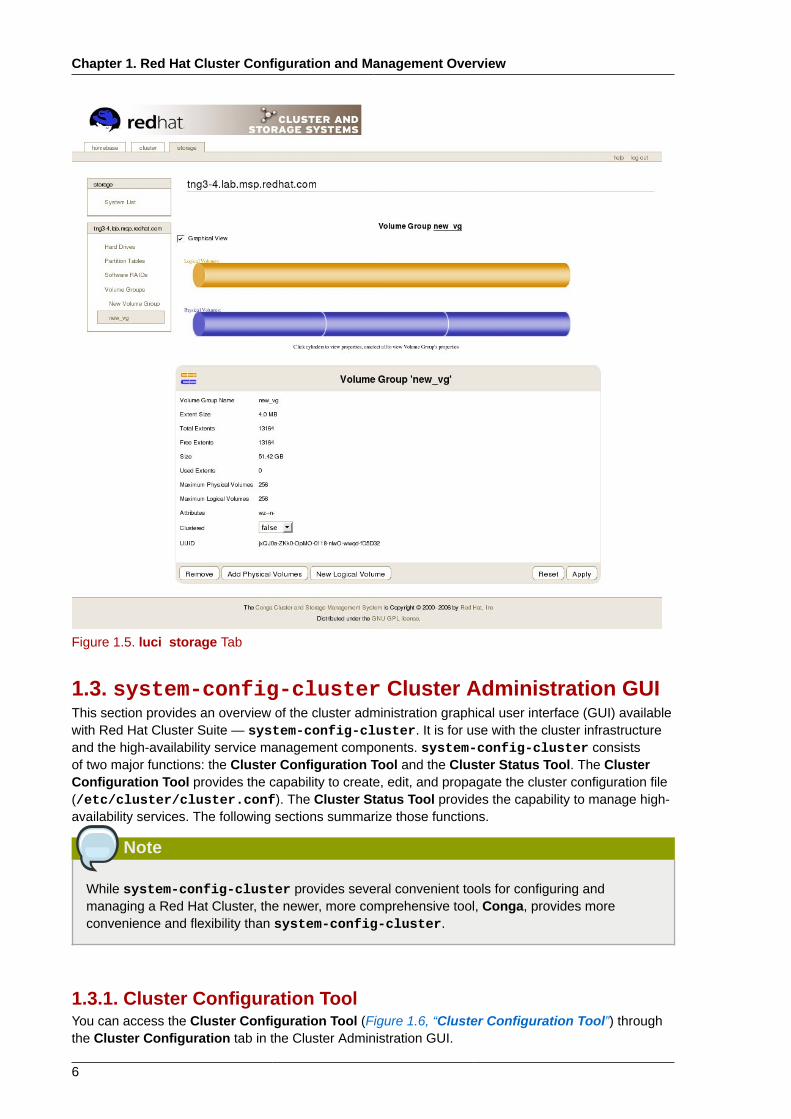
Figure 1.5. luci storage Tab
1.3. system-config-cluster Cluster Administration GUIThis section provides an overview of the cluster administration graphical user interface (GUI) availablewith Red Hat Cluster Suite — system-config-cluster. It is for use with the cluster infrastructureand the high-availability service management components. system-config-cluster consistsof two major functions: the Cluster Configuration Tool and the Cluster Status Tool. The ClusterConfiguration Tool provides the capability to create, edit, and propagate the cluster configuration file(/etc/cluster/cluster.conf). The Cluster Status Tool provides the capability to manage high-availability services. The following sections summarize those functions.
Note
While system-config-cluster provides several convenient tools for configuring andmanaging a Red Hat Cluster, the newer, more comprehensive tool, Conga, provides moreconvenience and flexibility than system-config-cluster.
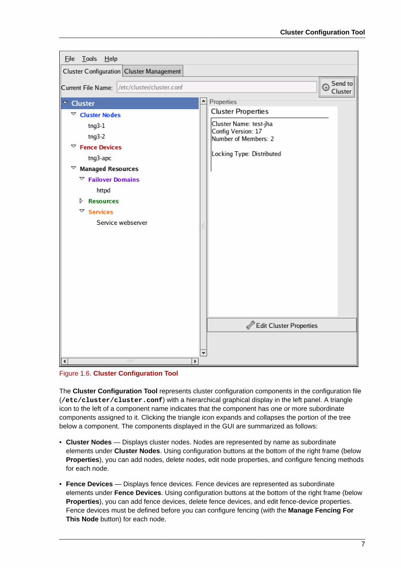
1.3.1. Cluster Configuration ToolYou can access the Cluster Configuration Tool (Figure 1.6, “Cluster Configuration Tool”) throughthe Cluster Configuration tab in the Cluster Administration GUI.
Cluster Configuration Tool
7
Figure 1.6. Cluster Configuration Tool
The Cluster Configuration Tool represents cluster configuration components in the configuration file(/etc/cluster/cluster.conf) with a hierarchical graphical display in the left panel. A triangleicon to the left of a component name indicates that the component has one or more subordinatecomponents assigned to it. Clicking the triangle icon expands and collapses the portion of the treebelow a component. The components displayed in the GUI are summarized as follows:
• Cluster Nodes — Displays cluster nodes. Nodes are represented by name as subordinateelements under Cluster Nodes. Using configuration buttons at the bottom of the right frame (belowProperties), you can add nodes, delete nodes, edit node properties, and configure fencing methodsfor each node.
• Fence Devices — Displays fence devices. Fence devices are represented as subordinateelements under Fence Devices. Using configuration buttons at the bottom of the right frame (belowProperties), you can add fence devices, delete fence devices, and edit fence-device properties.Fence devices must be defined before you can configure fencing (with the Manage Fencing ForThis Node button) for each node.
Chapter 1. Red Hat Cluster Configuration and Management Overview
8
• Managed Resources — Displays failover domains, resources, and services.
• Failover Domains — For configuring one or more subsets of cluster nodes used to run a high-availability service in the event of a node failure. Failover domains are represented as subordinateelements under Failover Domains. Using configuration buttons at the bottom of the right frame(below Properties), you can create failover domains (when Failover Domains is selected) or editfailover domain properties (when a failover domain is selected).
• Resources — For configuring shared resources to be used by high-availability services. Sharedresources consist of file systems, IP addresses, NFS mounts and exports, and user-createdscripts that are available to any high-availability service in the cluster. Resources are representedas subordinate elements under Resources. Using configuration buttons at the bottom of theright frame (below Properties), you can create resources (when Resources is selected) or editresource properties (when a resource is selected).
Note
The Cluster Configuration Tool provides the capability to configure private resources, also.A private resource is a resource that is configured for use with only one service. You canconfigure a private resource within a Service component in the GUI.
• Services — For creating and configuring high-availability services. A service is configured byassigning resources (shared or private), assigning a failover domain, and defining a recoverypolicy for the service. Services are represented as subordinate elements under Services. Usingconfiguration buttons at the bottom of the right frame (below Properties), you can create services(when Services is selected) or edit service properties (when a service is selected).
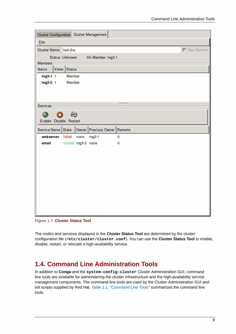
1.3.2. Cluster Status ToolYou can access the Cluster Status Tool (Figure 1.7, “Cluster Status Tool”) through the ClusterManagement tab in Cluster Administration GUI.
Command Line Administration Tools
9
Figure 1.7. Cluster Status Tool
The nodes and services displayed in the Cluster Status Tool are determined by the clusterconfiguration file (/etc/cluster/cluster.conf). You can use the Cluster Status Tool to enable,disable, restart, or relocate a high-availability service.
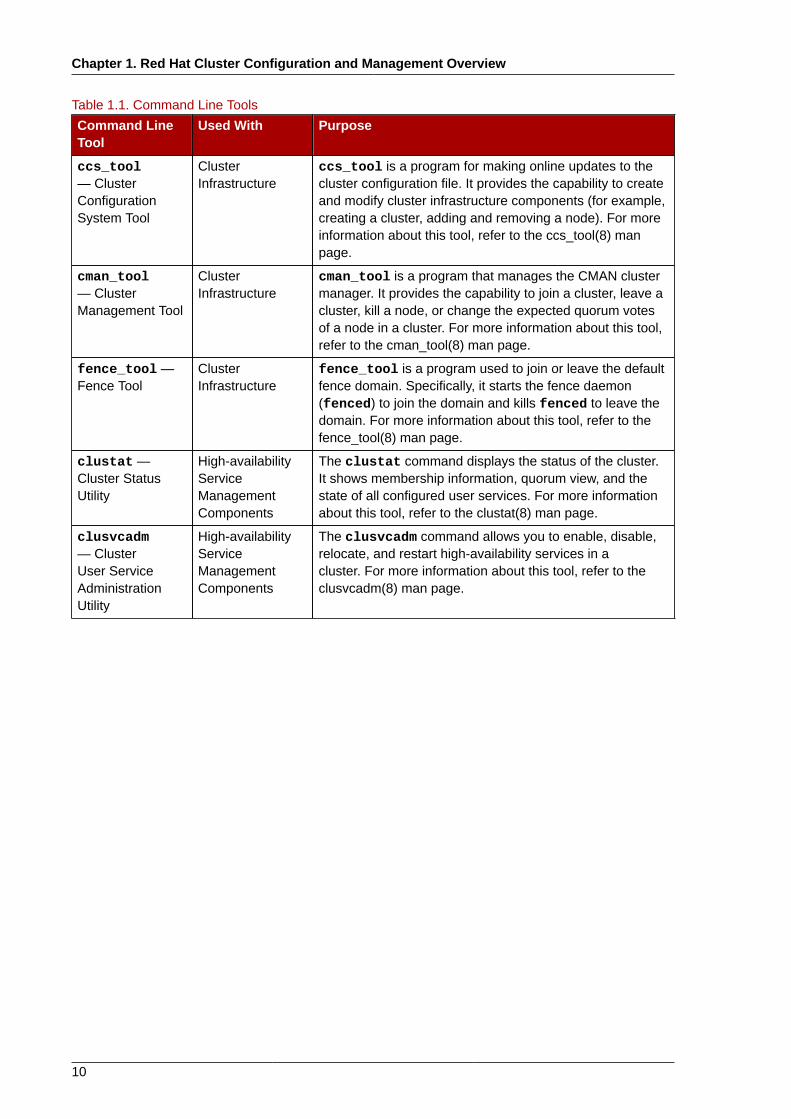
1.4. Command Line Administration ToolsIn addition to Conga and the system-config-cluster Cluster Administration GUI, commandline tools are available for administering the cluster infrastructure and the high-availability servicemanagement components. The command line tools are used by the Cluster Administration GUI andinit scripts supplied by Red Hat. Table 1.1, “Command Line Tools” summarizes the command linetools.
Chapter 1. Red Hat Cluster Configuration and Management Overview
10
Table 1.1. Command Line Tools
Command LineTool
Used With Purpose
ccs_tool— ClusterConfigurationSystem Tool
ClusterInfrastructure
ccs_tool is a program for making online updates to thecluster configuration file. It provides the capability to createand modify cluster infrastructure components (for example,creating a cluster, adding and removing a node). For moreinformation about this tool, refer to the ccs_tool(8) manpage.
cman_tool— ClusterManagement Tool
ClusterInfrastructure
cman_tool is a program that manages the CMAN clustermanager. It provides the capability to join a cluster, leave acluster, kill a node, or change the expected quorum votesof a node in a cluster. For more information about this tool,refer to the cman_tool(8) man page.
fence_tool —Fence Tool
ClusterInfrastructure
fence_tool is a program used to join or leave the defaultfence domain. Specifically, it starts the fence daemon(fenced) to join the domain and kills fenced to leave thedomain. For more information about this tool, refer to thefence_tool(8) man page.
clustat —Cluster StatusUtility
High-availabilityServiceManagementComponents
The clustat command displays the status of the cluster.It shows membership information, quorum view, and thestate of all configured user services. For more informationabout this tool, refer to the clustat(8) man page.
clusvcadm— ClusterUser ServiceAdministrationUtility
High-availabilityServiceManagementComponents
The clusvcadm command allows you to enable, disable,relocate, and restart high-availability services in acluster. For more information about this tool, refer to theclusvcadm(8) man page.
Chapter 2.
11
Before Configuring a Red Hat ClusterThis chapter describes tasks to perform and considerations to make before installing and configuring aRed Hat Cluster, and consists of the following sections.
Important
Make sure that your deployment of Red Hat Cluster Suite meets your needs and can besupported. Consult with an authorized Red Hat representive to verify Cluster Suite and GFSconfiguration prior to deployment. In addition, allow time for a configuration burn-in period to testfailure modes.
• Section 2.1, “General Configuration Considerations”
• Section 2.2, “Compatible Hardware”
• Section 2.3, “Enabling IP Ports”
• Section 2.4, “Configuring ACPI For Use with Integrated Fence Devices”
• Section 2.6, “Configuring max_luns”
• Section 2.7, “Considerations for Using Quorum Disk”
• Section 2.8, “Red Hat Cluster Suite and SELinux”
• Section 2.9, “Multicast Addresses”
• Section 2.10, “Considerations for Using Conga”
2.1. General Configuration ConsiderationsYou can configure a Red Hat Cluster in a variety of ways to suit your needs. Take into account thefollowing general considerations when you plan, configure, and implement your Red Hat Cluster.
Number of cluster nodes supportedThe maximum number of nodes supported in a Red Hat Cluster is 16.
GFS/GFS2Although a GFS/GFS2 file system can be implemented in a standalone system or as part of acluster configuration, for the RHEL 5.5 release and later, Red Hat does not support the use ofGFS/GFS2 as a single-node file system. Red Hat does support a number of high-performancesingle-node file systems that are optimized for single node, and thus have generally loweroverhead than a cluster file system. Red Hat recommends using those file systems in preferenceto GFS/GFS2 in cases where only a single node needs to mount the file system. Red Hat willcontinue to support single-node GFS/GFS2 file systems for existing customers.
When you configure a GFS/GFS2 file system as a cluster file system, you must ensure that allnodes in the cluster have access to the shared file system. Asymmetric cluster configurations inwhich some nodes have access to the file system and others do not are not supported.This doesnot require that all nodes actually mount the GFS/GFS2 file system itself.
Chapter 2. Before Configuring a Red Hat Cluster
12
No-single-point-of-failure hardware configurationClusters can include a dual-controller RAID array, multiple bonded network channels, multiplepaths between cluster members and storage, and redundant un-interruptible power supply (UPS)systems to ensure that no single failure results in application down time or loss of data.
Alternatively, a low-cost cluster can be set up to provide less availability than a no-single-point-of-failure cluster. For example, you can set up a cluster with a single-controller RAID array and only asingle Ethernet channel.
Certain low-cost alternatives, such as host RAID controllers, software RAID without clustersupport, and multi-initiator parallel SCSI configurations are not compatible or appropriate for useas shared cluster storage.
Data integrity assuranceTo ensure data integrity, only one node can run a cluster service and access cluster-service dataat a time. The use of power switches in the cluster hardware configuration enables a node topower-cycle another node before restarting that node's HA services during a failover process. Thisprevents two nodes from simultaneously accessing the same data and corrupting it. It is stronglyrecommended that fence devices (hardware or software solutions that remotely power, shutdown,and reboot cluster nodes) are used to guarantee data integrity under all failure conditions.Watchdog timers provide an alternative way to to ensure correct operation of HA service failover.
Ethernet channel bondingCluster quorum and node health is determined by communication of messages among clusternodes via Ethernet. In addition, cluster nodes use Ethernet for a variety of other critical clusterfunctions (for example, fencing). With Ethernet channel bonding, multiple Ethernet interfaces areconfigured to behave as one, reducing the risk of a single-point-of-failure in the typical switchedEthernet connection among cluster nodes and other cluster hardware.
2.2. Compatible HardwareBefore configuring Red Hat Cluster software, make sure that your cluster uses appropriate hardware(for example, supported fence devices, storage devices, and Fibre Channel switches). Refer to thehardware configuration guidelines at http://www.redhat.com/cluster_suite/hardware/ for the mostcurrent hardware compatibility information.
2.3. Enabling IP PortsBefore deploying a Red Hat Cluster, you must enable certain IP ports on the cluster nodes and oncomputers that run luci (the Conga user interface server). The following sections identify the IP portsto be enabled:
• Section 2.3.1, “Enabling IP Ports on Cluster Nodes”
• Section 2.3.2, “Enabling IP Ports on Computers That Run luci”
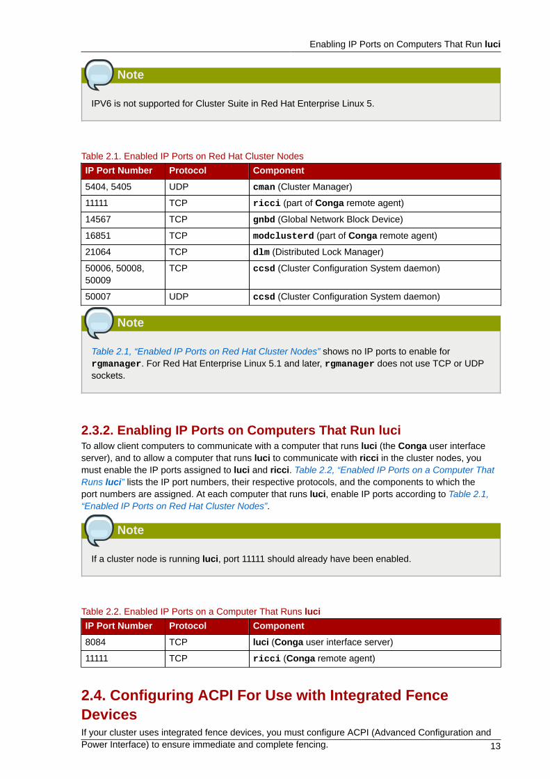
2.3.1. Enabling IP Ports on Cluster NodesTo allow Red Hat Cluster nodes to communicate with each other, you must enable the IP portsassigned to certain Red Hat Cluster components. Table 2.1, “Enabled IP Ports on Red Hat ClusterNodes” lists the IP port numbers, their respective protocols, and the components to which the portnumbers are assigned. At each cluster node, enable IP ports according to Table 2.1, “Enabled IP Portson Red Hat Cluster Nodes”.
Enabling IP Ports on Computers That Run luci
13
Note
IPV6 is not supported for Cluster Suite in Red Hat Enterprise Linux 5.
Table 2.1. Enabled IP Ports on Red Hat Cluster Nodes
IP Port Number Protocol Component
5404, 5405 UDP cman (Cluster Manager)
11111 TCP ricci (part of Conga remote agent)
14567 TCP gnbd (Global Network Block Device)
16851 TCP modclusterd (part of Conga remote agent)
21064 TCP dlm (Distributed Lock Manager)
50006, 50008,50009
TCP ccsd (Cluster Configuration System daemon)
50007 UDP ccsd (Cluster Configuration System daemon)
Note
Table 2.1, “Enabled IP Ports on Red Hat Cluster Nodes” shows no IP ports to enable forrgmanager. For Red Hat Enterprise Linux 5.1 and later, rgmanager does not use TCP or UDPsockets.
2.3.2. Enabling IP Ports on Computers That Run luciTo allow client computers to communicate with a computer that runs luci (the Conga user interfaceserver), and to allow a computer that runs luci to communicate with ricci in the cluster nodes, youmust enable the IP ports assigned to luci and ricci. Table 2.2, “Enabled IP Ports on a Computer ThatRuns luci” lists the IP port numbers, their respective protocols, and the components to which theport numbers are assigned. At each computer that runs luci, enable IP ports according to Table 2.1,“Enabled IP Ports on Red Hat Cluster Nodes”.
Note
If a cluster node is running luci, port 11111 should already have been enabled.
Table 2.2. Enabled IP Ports on a Computer That Runs luciIP Port Number Protocol Component
8084 TCP luci (Conga user interface server)
11111 TCP ricci (Conga remote agent)
2.4. Configuring ACPI For Use with Integrated FenceDevicesIf your cluster uses integrated fence devices, you must configure ACPI (Advanced Configuration andPower Interface) to ensure immediate and complete fencing.
Chapter 2. Before Configuring a Red Hat Cluster
14
Note
For the most current information about integrated fence devices supported by Red Hat ClusterSuite, refer to http://www.redhat.com/cluster_suite/hardware/1.
If a cluster node is configured to be fenced by an integrated fence device, disable ACPI Soft-Off forthat node. Disabling ACPI Soft-Off allows an integrated fence device to turn off a node immediatelyand completely rather than attempting a clean shutdown (for example, shutdown -h now).Otherwise, if ACPI Soft-Off is enabled, an integrated fence device can take four or more seconds toturn off a node (refer to note that follows). In addition, if ACPI Soft-Off is enabled and a node panicsor freezes during shutdown, an integrated fence device may not be able to turn off the node. Underthose circumstances, fencing is delayed or unsuccessful. Consequently, when a node is fencedwith an integrated fence device and ACPI Soft-Off is enabled, a cluster recovers slowly or requiresadministrative intervention to recover.
Note
The amount of time required to fence a node depends on the integrated fence device used.Some integrated fence devices perform the equivalent of pressing and holding the power button;therefore, the fence device turns off the node in four to five seconds. Other integrated fencedevices perform the equivalent of pressing the power button momentarily, relying on the operatingsystem to turn off the node; therefore, the fence device turns off the node in a time span muchlonger than four to five seconds.
To disable ACPI Soft-Off, use chkconfig management and verify that the node turns off immediatelywhen fenced. The preferred way to disable ACPI Soft-Off is with chkconfig management: however,if that method is not satisfactory for your cluster, you can disable ACPI Soft-Off with one of thefollowing alternate methods:
• Changing the BIOS setting to "instant-off" or an equivalent setting that turns off the node withoutdelay
Note
Disabling ACPI Soft-Off with the BIOS may not be possible with some computers.
• Appending acpi=off to the kernel boot command line of the /boot/grub/grub.conf file
1 http://www.redhat.com/cluster_suite/hardware/
Disabling ACPI Soft-Off with chkconfig Management
15
Important
This method completely disables ACPI; some computers do not boot correctly if ACPI iscompletely disabled. Use this method only if the other methods are not effective for yourcluster.
The following sections provide procedures for the preferred method and alternate methods of disablingACPI Soft-Off:
• Section 2.4.1, “Disabling ACPI Soft-Off with chkconfig Management” — Preferred method
• Section 2.4.2, “Disabling ACPI Soft-Off with the BIOS” — First alternate method
• Section 2.4.3, “Disabling ACPI Completely in the grub.conf File” — Second alternate method
2.4.1. Disabling ACPI Soft-Off with chkconfig ManagementYou can use chkconfig management to disable ACPI Soft-Off either by removing the ACPI daemon(acpid) from chkconfig management or by turning off acpid.
Note
This is the preferred method of disabling ACPI Soft-Off.
Disable ACPI Soft-Off with chkconfig management at each cluster node as follows:
1. Run either of the following commands:
• chkconfig --del acpid — This command removes acpid from chkconfig management.
— OR —
• chkconfig --level 2345 acpid off — This command turns off acpid.
2. Reboot the node.
3. When the cluster is configured and running, verify that the node turns off immediately whenfenced.
Note
You can fence the node with the fence_node command or Conga.
2.4.2. Disabling ACPI Soft-Off with the BIOSThe preferred method of disabling ACPI Soft-Off is with chkconfig management (Section 2.4.1,“Disabling ACPI Soft-Off with chkconfig Management”). However, if the preferred method is noteffective for your cluster, follow the procedure in this section.
Chapter 2. Before Configuring a Red Hat Cluster
16
Note
Disabling ACPI Soft-Off with the BIOS may not be possible with some computers.
You can disable ACPI Soft-Off by configuring the BIOS of each cluster node as follows:
1. Reboot the node and start the BIOS CMOS Setup Utility program.
2. Navigate to the Power menu (or equivalent power management menu).
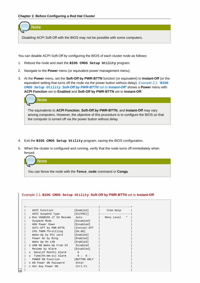
3. At the Power menu, set the Soft-Off by PWR-BTTN function (or equivalent) to Instant-Off (or theequivalent setting that turns off the node via the power button without delay). Example 2.1, “BIOSCMOS Setup Utility: Soft-Off by PWR-BTTN set to Instant-Off” shows a Power menu withACPI Function set to Enabled and Soft-Off by PWR-BTTN set to Instant-Off.
Note
The equivalents to ACPI Function, Soft-Off by PWR-BTTN, and Instant-Off may varyamong computers. However, the objective of this procedure is to configure the BIOS so thatthe computer is turned off via the power button without delay.
4. Exit the BIOS CMOS Setup Utility program, saving the BIOS configuration.
5. When the cluster is configured and running, verify that the node turns off immediately whenfenced.
Note
You can fence the node with the fence_node command or Conga.
Example 2.1. BIOS CMOS Setup Utility: Soft-Off by PWR-BTTN set to Instant-Off
+---------------------------------------------|-------------------+| ACPI Function [Enabled] | Item Help || ACPI Suspend Type [S1(POS)] |-------------------|| x Run VGABIOS if S3 Resume Auto | Menu Level * || Suspend Mode [Disabled] | || HDD Power Down [Disabled] | || Soft-Off by PWR-BTTN [Instant-Off | || CPU THRM-Throttling [50.0%] | || Wake-Up by PCI card [Enabled] | || Power On by Ring [Enabled] | || Wake Up On LAN [Enabled] | || x USB KB Wake-Up From S3 Disabled | || Resume by Alarm [Disabled] | || x Date(of Month) Alarm 0 | || x Time(hh:mm:ss) Alarm 0 : 0 : | || POWER ON Function [BUTTON ONLY | || x KB Power ON Password Enter | || x Hot Key Power ON Ctrl-F1 | || | |
Disabling ACPI Completely in the grub.conf File
17
| | |+---------------------------------------------|-------------------+
This example shows ACPI Function set to Enabled, and Soft-Off by PWR-BTTN set to Instant-Off.
2.4.3. Disabling ACPI Completely in the grub.conf FileThe preferred method of disabling ACPI Soft-Off is with chkconfig management (Section 2.4.1,“Disabling ACPI Soft-Off with chkconfig Management”). If the preferred method is not effectivefor your cluster, you can disable ACPI Soft-Off with the BIOS power management (Section 2.4.2,“Disabling ACPI Soft-Off with the BIOS”). If neither of those methods is effective for your cluster,you can disable ACPI completely by appending acpi=off to the kernel boot command line in thegrub.conf file.
Important
This method completely disables ACPI; some computers do not boot correctly if ACPI iscompletely disabled. Use this method only if the other methods are not effective for your cluster.
You can disable ACPI completely by editing the grub.conf file of each cluster node as follows:
1. Open /boot/grub/grub.conf with a text editor.
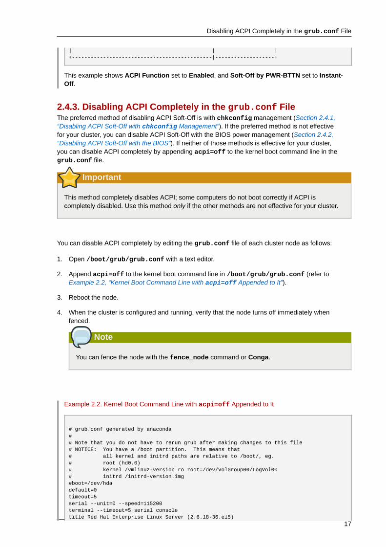
2. Append acpi=off to the kernel boot command line in /boot/grub/grub.conf (refer toExample 2.2, “Kernel Boot Command Line with acpi=off Appended to It”).
3. Reboot the node.
4. When the cluster is configured and running, verify that the node turns off immediately whenfenced.
Note
You can fence the node with the fence_node command or Conga.
Example 2.2. Kernel Boot Command Line with acpi=off Appended to It
# grub.conf generated by anaconda## Note that you do not have to rerun grub after making changes to this file# NOTICE: You have a /boot partition. This means that# all kernel and initrd paths are relative to /boot/, eg.# root (hd0,0)# kernel /vmlinuz-version ro root=/dev/VolGroup00/LogVol00# initrd /initrd-version.img#boot=/dev/hdadefault=0timeout=5serial --unit=0 --speed=115200terminal --timeout=5 serial consoletitle Red Hat Enterprise Linux Server (2.6.18-36.el5)
Chapter 2. Before Configuring a Red Hat Cluster
18
root (hd0,0) kernel /vmlinuz-2.6.18-36.el5 ro root=/dev/VolGroup00/LogVol00 console=ttyS0,115200n8 acpi=off initrd /initrd-2.6.18-36.el5.img
In this example, acpi=off has been appended to the kernel boot command line — the line startingwith "kernel /vmlinuz-2.6.18-36.el5".
2.5. Considerations for Configuring HA ServicesYou can create a cluster to suit your needs for high availability by configuring HA (high-availability)services. The key component for HA service management in a Red Hat cluster, rgmanager,implements cold failover for off-the-shelf applications. In a Red Hat cluster, an application is configuredwith other cluster resources to form an HA service that can fail over from one cluster node to anotherwith no apparent interruption to cluster clients. HA-service failover can occur if a cluster node fails or ifa cluster system administrator moves the service from one cluster node to another (for example, for aplanned outage of a cluster node).
To create an HA service, you must configure it in the cluster configuration file. An HA servicecomprises cluster resources. Cluster resources are building blocks that you create and manage in thecluster configuration file — for example, an IP address, an application initialization script, or a Red HatGFS shared partition.
An HA service can run on only one cluster node at a time to maintain data integrity. You can specifyfailover priority in a failover domain. Specifying failover priority consists of assigning a priority level toeach node in a failover domain. The priority level determines the failover order — determining whichnode that an HA service should fail over to. If you do not specify failover priority, an HA service can failover to any node in its failover domain. Also, you can specify if an HA service is restricted to run onlyon nodes of its associated failover domain. (When associated with an unrestricted failover domain, anHA service can start on any cluster node in the event no member of the failover domain is available.)
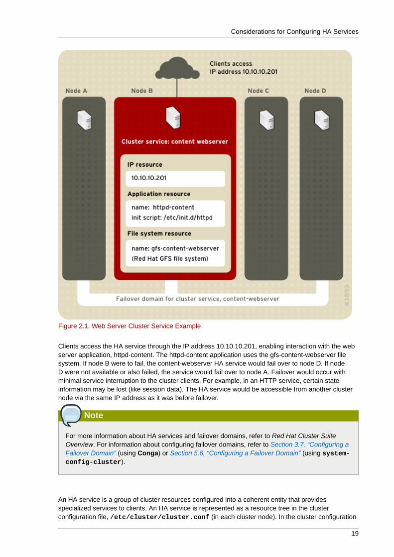
Figure 2.1, “Web Server Cluster Service Example” shows an example of an HA service that is a webserver named "content-webserver". It is running in cluster node B and is in a failover domain thatconsists of nodes A, B, and D. In addition, the failover domain is configured with a failover priority tofail over to node D before node A and to restrict failover to nodes only in that failover domain. The HAservice comprises these cluster resources:
• IP address resource — IP address 10.10.10.201.
• An application resource named "httpd-content" — a web server application init script /etc/init.d/httpd (specifying httpd).
• A file system resource — Red Hat GFS named "gfs-content-webserver".
Considerations for Configuring HA Services
19
Figure 2.1. Web Server Cluster Service Example
Clients access the HA service through the IP address 10.10.10.201, enabling interaction with the webserver application, httpd-content. The httpd-content application uses the gfs-content-webserver filesystem. If node B were to fail, the content-webserver HA service would fail over to node D. If nodeD were not available or also failed, the service would fail over to node A. Failover would occur withminimal service interruption to the cluster clients. For example, in an HTTP service, certain stateinformation may be lost (like session data). The HA service would be accessible from another clusternode via the same IP address as it was before failover.
Note
For more information about HA services and failover domains, refer to Red Hat Cluster SuiteOverview. For information about configuring failover domains, refer to Section 3.7, “Configuring aFailover Domain” (using Conga) or Section 5.6, “Configuring a Failover Domain” (using system-config-cluster).
An HA service is a group of cluster resources configured into a coherent entity that providesspecialized services to clients. An HA service is represented as a resource tree in the clusterconfiguration file, /etc/cluster/cluster.conf (in each cluster node). In the cluster configuration
Chapter 2. Before Configuring a Red Hat Cluster
20
file, each resource tree is an XML representation that specifies each resource, its attributes, and itsrelationship among other resources in the resource tree (parent, child, and sibling relationships).
Note
Because an HA service consists of resources organized into a hierarchical tree, a service issometimes referred to as a resource tree or resource group. Both phrases are synonymous withHA service.
At the root of each resource tree is a special type of resource — a service resource. Other types ofresources comprise the rest of a service, determining its characteristics. Configuring an HA serviceconsists of creating a service resource, creating subordinate cluster resources, and organizing theminto a coherent entity that conforms to hierarchical restrictions of the service.
Red Hat Cluster supports the following HA services:
• Apache
• Application (Script)
• LVM (HA LVM)
• MySQL
• NFS
• Open LDAP
• Oracle
• PostgreSQL 8
• Samba
• SAP
• Tomcat 5
There are two major considerations to take into account when configuring an HA service:
• The types of resources needed to create a service
• Parent, child, and sibling relationships among resources
The types of resources and the hierarchy of resources depend on the type of service you areconfiguring.
The types of cluster resources are listed in Appendix C, HA Resource Parameters. Information aboutparent, child, and sibling relationships among resources is described in Appendix D, HA ResourceBehavior.
2.6. Configuring max_lunsIt is not necessary to configure max_luns in Red Hat Enterprise Linux 5.
In Red Hat Enterprise Linux releases prior to Red Hat Enterprise Linux 5, if RAID storage in a clusterpresents multiple LUNs, it is necessary to enable access to those LUNs by configuring max_luns
Considerations for Using Quorum Disk
21
(or max_scsi_luns for 2.4 kernels) in the /etc/modprobe.conf file of each node. In RedHat Enterprise Linux 5, cluster nodes detect multiple LUNs without intervention required; it is notnecessary to configure max_luns to detect multiple LUNs.
2.7. Considerations for Using Quorum DiskQuorum Disk is a disk-based quorum daemon, qdiskd, that provides supplemental heuristics todetermine node fitness. With heuristics you can determine factors that are important to the operationof the node in the event of a network partition. For example, in a four-node cluster with a 3:1 split,ordinarily, the three nodes automatically "win" because of the three-to-one majority. Under thosecircumstances, the one node is fenced. With qdiskd however, you can set up heuristics that allow theone node to win based on access to a critical resource (for example, a critical network path). If yourcluster requires additional methods of determining node health, then you should configure qdiskd tomeet those needs.
Note
Configuring qdiskd is not required unless you have special requirements for node health. Anexample of a special requirement is an "all-but-one" configuration. In an all-but-one configuration,qdiskd is configured to provide enough quorum votes to maintain quorum even though only onenode is working.
Important
Overall, heuristics and other qdiskd parameters for your Red Hat Cluster depend on the siteenvironment and special requirements needed. To understand the use of heuristics and otherqdiskd parameters, refer to the qdisk(5) man page. If you require assistance understanding andusing qdiskd for your site, contact an authorized Red Hat support representative.
If you need to use qdiskd, you should take into account the following considerations:
Cluster node votesEach cluster node should have the same number of votes.
CMAN membership timeout valueThe CMAN membership timeout value (the time a node needs to be unresponsive before CMANconsiders that node to be dead, and not a member) should be at least two times that of theqdiskd membership timeout value. The reason is because the quorum daemon must detectfailed nodes on its own, and can take much longer to do so than CMAN. The default valuefor CMAN membership timeout is 10 seconds. Other site-specific conditions may affect therelationship between the membership timeout values of CMAN and qdiskd. For assistancewith adjusting the CMAN membership timeout value, contact an authorized Red Hat supportrepresentative.
FencingTo ensure reliable fencing when using qdiskd, use power fencing. While other types of fencing(such as watchdog timers and software-based solutions to reboot a node internally) can be reliablefor clusters not configured with qdiskd, they are not reliable for a cluster configured with qdiskd.
Chapter 2. Before Configuring a Red Hat Cluster
22
Maximum nodesA cluster configured with qdiskd supports a maximum of 16 nodes. The reason for the limitis because of scalability; increasing the node count increases the amount of synchronous I/Ocontention on the shared quorum disk device.
Quorum disk deviceA quorum disk device should be a shared block device with concurrent read/write access byall nodes in a cluster. The minimum size of the block device is 10 Megabytes. Examples ofshared block devices that can be used by qdiskd are a multi-port SCSI RAID array, a FibreChannel RAID SAN, or a RAID-configured iSCSI target. You can create a quorum disk devicewith mkqdisk, the Cluster Quorum Disk Utility. For information about using the utility refer to themkqdisk(8) man page.
Note
Using JBOD as a quorum disk is not recommended. A JBOD cannot provide dependableperformance and therefore may not allow a node to write to it quickly enough. If a node isunable to write to a quorum disk device quickly enough, the node is falsely evicted from acluster.
2.8. Red Hat Cluster Suite and SELinuxRed Hat Cluster Suite supports SELinux states according to the Red Hat Enterprise Linux releaselevel deployed in your cluster as follows:• Red Hat Enterprise Linux 5.4 and earlier — disabled state only.
• Red Hat Enterprise Linux 5.5 and later — enforcing or permissive state with the SELinuxpolicy type set to targeted (or with the state set to disabled).
For more information about SELinux, refer to Deployment Guide for Red Hat Enterprise Linux 5.
2.9. Multicast AddressesRed Hat Cluster nodes communicate among each other using multicast addresses. Therefore, eachnetwork switch and associated networking equipment in a Red Hat Cluster must be configured toenable multicast addresses and support IGMP (Internet Group Management Protocol). Ensure thateach network switch and associated networking equipment in a Red Hat Cluster are capable ofsupporting multicast addresses and IGMP; if they are, ensure that multicast addressing and IGMP areenabled. Without multicast and IGMP, not all nodes can participate in a cluster, causing the cluster tofail.
Note
Procedures for configuring network switches and associated networking equipment varyaccording each product. Refer to the appropriate vendor documentation or other informationabout configuring network switches and associated networking equipment to enable multicastaddresses and IGMP.
Considerations for Using Conga
23
Note
IPV6 is not supported for Cluster Suite in Red Hat Enterprise Linux 5.
2.10. Considerations for Using CongaWhen using Conga to configure and manage your Red Hat Cluster, make sure that each computerrunning luci (the Conga user interface server) is running on the same network that the cluster is usingfor cluster communication. Otherwise, luci cannot configure the nodes to communicate on the rightnetwork. If the computer running luci is on another network (for example, a public network ratherthan a private network that the cluster is communicating on), contact an authorized Red Hat supportrepresentative to make sure that the appropriate host name is configured for each cluster node.

24
Chapter 3.
25
Configuring Red Hat Cluster WithCongaThis chapter describes how to configure Red Hat Cluster software using Conga, and consists of thefollowing sections:
• Section 3.1, “Configuration Tasks”
• Section 3.2, “Starting luci and ricci”
• Section 3.3, “Creating A Cluster”
• Section 3.4, “Global Cluster Properties”
• Section 3.5, “Configuring Fence Devices”
• Section 3.6, “Configuring Cluster Members”
• Section 3.7, “Configuring a Failover Domain”
• Section 3.8, “Adding Cluster Resources”
• Section 3.9, “Adding a Cluster Service to the Cluster”
• Section 3.10, “Configuring Cluster Storage”
3.1. Configuration TasksConfiguring Red Hat Cluster software with Conga consists of the following steps:
1. Configuring and running the Conga configuration user interface — the luci server. Refer toSection 3.2, “Starting luci and ricci”.
2. Creating a cluster. Refer to Section 3.3, “Creating A Cluster”.
3. Configuring global cluster properties. Refer to Section 3.4, “Global Cluster Properties”.
4. Configuring fence devices. Refer to Section 3.5, “Configuring Fence Devices”.
5. Configuring cluster members. Refer to Section 3.6, “Configuring Cluster Members”.
6. Creating failover domains. Refer to Section 3.7, “Configuring a Failover Domain”.
7. Creating resources. Refer to Section 3.8, “Adding Cluster Resources”.
8. Creating cluster services. Refer to Section 3.9, “Adding a Cluster Service to the Cluster”.
9. Configuring storage. Refer to Section 3.10, “Configuring Cluster Storage”.
3.2. Starting luci and ricciTo administer Red Hat Clusters with Conga, install and run luci and ricci as follows:
1. At each node to be administered by Conga, install the ricci agent. For example:
Chapter 3. Configuring Red Hat Cluster With Conga
26
# yum install ricci
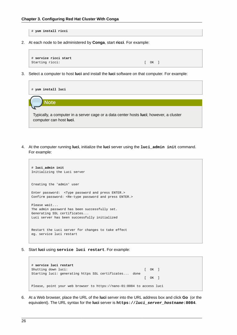
2. At each node to be administered by Conga, start ricci. For example:
# service ricci startStarting ricci: [ OK ]
3. Select a computer to host luci and install the luci software on that computer. For example:
# yum install luci
Note
Typically, a computer in a server cage or a data center hosts luci; however, a clustercomputer can host luci.
4. At the computer running luci, initialize the luci server using the luci_admin init command.For example:
# luci_admin initInitializing the Luci server
Creating the 'admin' user
Enter password: <Type password and press ENTER.>Confirm password: <Re-type password and press ENTER.>
Please wait...The admin password has been successfully set.Generating SSL certificates...Luci server has been successfully initialized
Restart the Luci server for changes to take effecteg. service luci restart
5. Start luci using service luci restart. For example:
# service luci restartShutting down luci: [ OK ]Starting luci: generating https SSL certificates... done [ OK ]
Please, point your web browser to https://nano-01:8084 to access luci
6. At a Web browser, place the URL of the luci server into the URL address box and click Go (or theequivalent). The URL syntax for the luci server is https://luci_server_hostname:8084.
Creating A Cluster
27
The first time you access luci, two SSL certificate dialog boxes are displayed. Uponacknowledging the dialog boxes, your Web browser displays the luci login page.
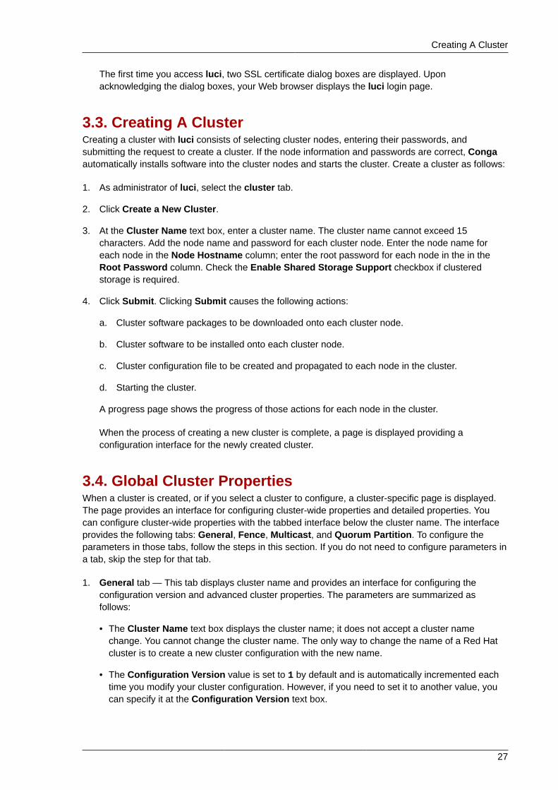
3.3. Creating A ClusterCreating a cluster with luci consists of selecting cluster nodes, entering their passwords, andsubmitting the request to create a cluster. If the node information and passwords are correct, Congaautomatically installs software into the cluster nodes and starts the cluster. Create a cluster as follows:
1. As administrator of luci, select the cluster tab.
2. Click Create a New Cluster.
3. At the Cluster Name text box, enter a cluster name. The cluster name cannot exceed 15characters. Add the node name and password for each cluster node. Enter the node name foreach node in the Node Hostname column; enter the root password for each node in the in theRoot Password column. Check the Enable Shared Storage Support checkbox if clusteredstorage is required.
4. Click Submit. Clicking Submit causes the following actions:
a. Cluster software packages to be downloaded onto each cluster node.
b. Cluster software to be installed onto each cluster node.
c. Cluster configuration file to be created and propagated to each node in the cluster.
d. Starting the cluster.
A progress page shows the progress of those actions for each node in the cluster.
When the process of creating a new cluster is complete, a page is displayed providing aconfiguration interface for the newly created cluster.
3.4. Global Cluster PropertiesWhen a cluster is created, or if you select a cluster to configure, a cluster-specific page is displayed.The page provides an interface for configuring cluster-wide properties and detailed properties. Youcan configure cluster-wide properties with the tabbed interface below the cluster name. The interfaceprovides the following tabs: General, Fence, Multicast, and Quorum Partition. To configure theparameters in those tabs, follow the steps in this section. If you do not need to configure parameters ina tab, skip the step for that tab.
1. General tab — This tab displays cluster name and provides an interface for configuring theconfiguration version and advanced cluster properties. The parameters are summarized asfollows:
• The Cluster Name text box displays the cluster name; it does not accept a cluster namechange. You cannot change the cluster name. The only way to change the name of a Red Hatcluster is to create a new cluster configuration with the new name.
• The Configuration Version value is set to 1 by default and is automatically incremented eachtime you modify your cluster configuration. However, if you need to set it to another value, youcan specify it at the Configuration Version text box.
Chapter 3. Configuring Red Hat Cluster With Conga
28
• You can enter advanced cluster properties by clicking Show advanced cluster properties.Clicking Show advanced cluster properties reveals a list of advanced properties. You canclick any advanced property for online help about the property.
Enter the values required and click Apply for changes to take effect.
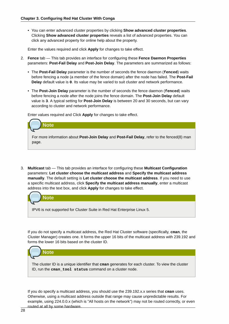
2. Fence tab — This tab provides an interface for configuring these Fence Daemon Propertiesparameters: Post-Fail Delay and Post-Join Delay. The parameters are summarized as follows:
• The Post-Fail Delay parameter is the number of seconds the fence daemon (fenced) waitsbefore fencing a node (a member of the fence domain) after the node has failed. The Post-FailDelay default value is 0. Its value may be varied to suit cluster and network performance.
• The Post-Join Delay parameter is the number of seconds the fence daemon (fenced) waitsbefore fencing a node after the node joins the fence domain. The Post-Join Delay defaultvalue is 3. A typical setting for Post-Join Delay is between 20 and 30 seconds, but can varyaccording to cluster and network performance.
Enter values required and Click Apply for changes to take effect.
Note
For more information about Post-Join Delay and Post-Fail Delay, refer to the fenced(8) manpage.
3. Multicast tab — This tab provides an interface for configuring these Multicast Configurationparameters: Let cluster choose the multicast address and Specify the multicast addressmanually. The default setting is Let cluster choose the multicast address. If you need to usea specific multicast address, click Specify the multicast address manually, enter a multicastaddress into the text box, and click Apply for changes to take effect.
Note
IPV6 is not supported for Cluster Suite in Red Hat Enterprise Linux 5.
If you do not specify a multicast address, the Red Hat Cluster software (specifically, cman, theCluster Manager) creates one. It forms the upper 16 bits of the multicast address with 239.192 andforms the lower 16 bits based on the cluster ID.
Note
The cluster ID is a unique identifier that cman generates for each cluster. To view the clusterID, run the cman_tool status command on a cluster node.
If you do specify a multicast address, you should use the 239.192.x.x series that cman uses.Otherwise, using a multicast address outside that range may cause unpredictable results. Forexample, using 224.0.0.x (which is "All hosts on the network") may not be routed correctly, or evenrouted at all by some hardware.
Global Cluster Properties
29
Note
If you specify a multicast address, make sure that you check the configuration of routersthat cluster packets pass through. Some routers may take a long time to learn addresses,seriously impacting cluster performance.
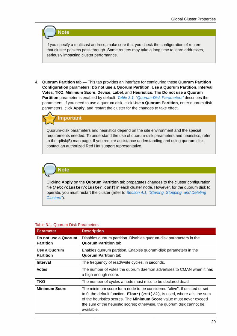
4. Quorum Partition tab — This tab provides an interface for configuring these Quorum PartitionConfiguration parameters: Do not use a Quorum Partition, Use a Quorum Partition, Interval,Votes, TKO, Minimum Score, Device, Label, and Heuristics. The Do not use a QuorumPartition parameter is enabled by default. Table 3.1, “Quorum-Disk Parameters” describes theparameters. If you need to use a quorum disk, click Use a Quorum Partition, enter quorum diskparameters, click Apply, and restart the cluster for the changes to take effect.
Important
Quorum-disk parameters and heuristics depend on the site environment and the specialrequirements needed. To understand the use of quorum-disk parameters and heuristics, referto the qdisk(5) man page. If you require assistance understanding and using quorum disk,contact an authorized Red Hat support representative.
Note
Clicking Apply on the Quorum Partition tab propagates changes to the cluster configurationfile (/etc/cluster/cluster.conf) in each cluster node. However, for the quorum disk tooperate, you must restart the cluster (refer to Section 4.1, “Starting, Stopping, and DeletingClusters”).
Table 3.1. Quorum-Disk Parameters
Parameter Description
Do not use a QuorumPartition
Disables quorum partition. Disables quorum-disk parameters in theQuorum Partition tab.
Use a QuorumPartition
Enables quorum partition. Enables quorum-disk parameters in theQuorum Partition tab.
Interval The frequency of read/write cycles, in seconds.
Votes The number of votes the quorum daemon advertises to CMAN when it hasa high enough score.
TKO The number of cycles a node must miss to be declared dead.
Minimum Score The minimum score for a node to be considered "alive". If omitted or setto 0, the default function, floor((n+1)/2), is used, where n is the sumof the heuristics scores. The Minimum Score value must never exceedthe sum of the heuristic scores; otherwise, the quorum disk cannot beavailable.

Chapter 3. Configuring Red Hat Cluster With Conga
30
Parameter Description
Device The storage device the quorum daemon uses. The device must be thesame on all nodes.
Label Specifies the quorum disk label created by the mkqdisk utility. If this fieldcontains an entry, the label overrides the Device field. If this field is used,the quorum daemon reads /proc/partitions and checks for qdisksignatures on every block device found, comparing the label against thespecified label. This is useful in configurations where the quorum devicename differs among nodes.
Heuristics Path to Program — The program used to determine if this heuristic isalive. This can be anything that can be executed by /bin/sh -c. A returnvalue of 0 indicates success; anything else indicates failure. This field isrequired.Interval — The frequency (in seconds) at which the heuristic is polled. Thedefault interval for every heuristic is 2 seconds.Score — The weight of this heuristic. Be careful when determining scoresfor heuristics. The default score for each heuristic is 1.
Apply Propagates the changes to the cluster configuration file (/etc/cluster/cluster.conf) in each cluster node.
3.5. Configuring Fence DevicesConfiguring fence devices consists of creating, modifying, and deleting fence devices. Creating afence device consists of selecting a fence device type and entering parameters for that fence device(for example, name, IP address, login, and password). Modifying a fence device consists of selectingan existing fence device and changing parameters for that fence device. Deleting a fence deviceconsists of selecting an existing fence device and deleting it.
Note
If you are creating a new cluster, you can create fence devices when you configure cluster nodes.Refer to Section 3.6, “Configuring Cluster Members”.
With Conga you can create shared and non-shared fence devices.
The following shared fence devices are available:
• APC Power Switch
• Brocade Fabric Switch
• Bull PAP
• Egenera SAN Controller
• GNBD
• IBM Blade Center
• McData SAN Switch
• QLogic SANbox2
Creating a Shared Fence Device
31
• SCSI Fencing (*See Note)
• Virtual Machine Fencing
• Vixel SAN Switch
• WTI Power Switch
Note
Use of SCSI persistent reservations as a fence method is supported with the following limitations:
• As of Red Hat Enterprise Linux 5.5 and fully-updated releases of Red Hat Enterprise Linux 5.4,SCSI fencing can be used in a 2-node cluster; previous releases did not support this feature.
• When using SCSI fencing, all nodes in the cluster must register with the same devices so thateach node can remove another node's registration key from all the devices it is registered with.
• Devices used for the cluster volumes should be a complete LUN, not partitions. SCSIpersistent reservations work on an entire LUN, meaning that access is controlled to each LUN,not individual partitions.
• As of Red Hat Enterprise Linux 5.5 and fully-updated releases of Red Hat Enterprise Linux5.4, SCSI fencing can be used in conjunction with qdisk; previous releases did not support thisfeature. You cannot use fence_scsi on the LUN where qdiskd resides; it must be a rawLUN or raw partition of a LUN.
The following non-shared fence devices are available:
• Dell DRAC
• HP iLO
• IBM RSA II
• IPMI LAN
• RPS10 Serial Switch
This section provides procedures for the following tasks:
• Creating shared fence devices — Refer to Section 3.5.1, “Creating a Shared Fence Device”. Theprocedures apply only to creating shared fence devices. You can create non-shared (and shared)fence devices while configuring nodes (refer to Section 3.6, “Configuring Cluster Members”).
• Modifying or deleting fence devices — Refer to Section 3.5.2, “Modifying or Deleting a FenceDevice”. The procedures apply to both shared and non-shared fence devices.
The starting point of each procedure is at the cluster-specific page that you navigate to from Choose acluster to administer displayed on the cluster tab.
3.5.1. Creating a Shared Fence DeviceTo create a shared fence device, follow these steps:
1. At the detailed menu for the cluster (below the clusters menu), click Shared Fence Devices.Clicking Shared Fence Devices causes the display of the fence devices for a cluster and causes
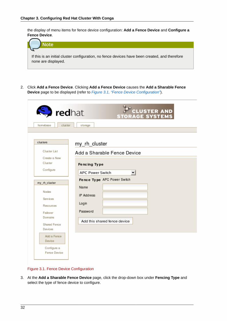
Chapter 3. Configuring Red Hat Cluster With Conga
32
the display of menu items for fence device configuration: Add a Fence Device and Configure aFence Device.
Note
If this is an initial cluster configuration, no fence devices have been created, and thereforenone are displayed.
2. Click Add a Fence Device. Clicking Add a Fence Device causes the Add a Sharable FenceDevice page to be displayed (refer to Figure 3.1, “Fence Device Configuration”).
Figure 3.1. Fence Device Configuration
3. At the Add a Sharable Fence Device page, click the drop-down box under Fencing Type andselect the type of fence device to configure.
Modifying or Deleting a Fence Device
33
4. Specify the information in the Fencing Type dialog box according to the type of fence device.Refer to Appendix B, Fence Device Parameters for more information about fence deviceparameters.
5. Click Add this shared fence device.
6. Clicking Add this shared fence device causes a progress page to be displayed temporarily. Afterthe fence device has been added, the detailed cluster properties menu is updated with the fencedevice under Configure a Fence Device.
3.5.2. Modifying or Deleting a Fence DeviceTo modify or delete a fence device, follow these steps:
1. At the detailed menu for the cluster (below the clusters menu), click Shared Fence Devices.Clicking Shared Fence Devices causes the display of the fence devices for a cluster and causesthe display of menu items for fence device configuration: Add a Fence Device and Configure aFence Device.
2. Click Configure a Fence Device. Clicking Configure a Fence Device causes the display of a listof fence devices under Configure a Fence Device.
3. Click a fence device in the list. Clicking a fence device in the list causes the display of a FenceDevice Form page for the fence device selected from the list.
4. Either modify or delete the fence device as follows:
• To modify the fence device, enter changes to the parameters displayed. Refer to Appendix B,Fence Device Parameters for more information about fence device parameters. Click Updatethis fence device and wait for the configuration to be updated.
• To delete the fence device, click Delete this fence device and wait for the configuration to beupdated.
Note
You can create shared fence devices on the node configuration page, also. However, youcan only modify or delete a shared fence device via Shared Fence Devices at the detailedmenu for the cluster (below the clusters menu).
3.6. Configuring Cluster MembersConfiguring cluster members consists of initially configuring nodes in a newly configured cluster,adding members, and deleting members. The following sections provide procedures for initialconfiguration of nodes, adding nodes, and deleting nodes:
• Section 3.6.1, “Initially Configuring Members”
• Section 3.6.2, “Adding a Member to a Running Cluster”
• Section 3.6.3, “Deleting a Member from a Cluster”
Chapter 3. Configuring Red Hat Cluster With Conga
34
3.6.1. Initially Configuring MembersCreating a cluster consists of selecting a set of nodes (or members) to be part of the cluster. Once youhave completed the initial step of creating a cluster and creating fence devices, you need to configurecluster nodes. To initially configure cluster nodes after creating a new cluster, follow the steps in thissection. The starting point of the procedure is at the cluster-specific page that you navigate to fromChoose a cluster to administer displayed on the cluster tab.
1. At the detailed menu for the cluster (below the clusters menu), click Nodes. Clicking Nodescauses the display of an Add a Node element and a Configure element with a list of the nodesalready configured in the cluster.
2. Click a link for a node at either the list in the center of the page or in the list in the detailed menuunder the clusters menu. Clicking a link for a node causes a page to be displayed for that linkshowing how that node is configured.
3. At the bottom of the page, under Main Fencing Method, click Add a fence device to this level.
4. Select a fence device and provide parameters for the fence device (for example port number).
Note
You can choose from an existing fence device or create a new fence device.
5. Click Update main fence properties and wait for the change to take effect.
3.6.2. Adding a Member to a Running ClusterTo add a member to a running cluster, follow the steps in this section. The starting point of theprocedure is at the cluster-specific page that you navigate to from Choose a cluster to administerdisplayed on the cluster tab.
1. At the detailed menu for the cluster (below the clusters menu), click Nodes. Clicking Nodescauses the display of an Add a Node element and a Configure element with a list of the nodesalready configured in the cluster. (In addition, a list of the cluster nodes is displayed in the centerof the page.)
2. Click Add a Node. Clicking Add a Node causes the display of the Add a node to clustername page.
3. At that page, enter the node name in the Node Hostname text box; enter the root password inthe Root Password text box. Check the Enable Shared Storage Support checkbox if clusteredstorage is required. If you want to add more nodes, click Add another entry and enter node nameand password for the each additional node.
4. Click Submit. Clicking Submit causes the following actions:
a. Cluster software packages to be downloaded onto the added node.
b. Cluster software to be installed (or verification that the appropriate software packages areinstalled) onto the added node.
c. Cluster configuration file to be updated and propagated to each node in the cluster —including the added node.
Deleting a Member from a Cluster
35
d. Joining the added node to cluster.
A progress page shows the progress of those actions for each added node.
5. When the process of adding a node is complete, a page is displayed providing a configurationinterface for the cluster.
6. At the detailed menu for the cluster (below the clusters menu), click Nodes. Clicking Nodescauses the following displays:
• A list of cluster nodes in the center of the page
• The Add a Node element and the Configure element with a list of the nodes configured in thecluster at the detailed menu for the cluster (below the clusters menu)
7. Click the link for an added node at either the list in the center of the page or in the list in thedetailed menu under the clusters menu. Clicking the link for the added node causes a page to bedisplayed for that link showing how that node is configured.
8. At the bottom of the page, under Main Fencing Method, click Add a fence device to this level.
9. Select a fence device and provide parameters for the fence device (for example port number).
Note
You can choose from an existing fence device or create a new fence device.
10. Click Update main fence properties and wait for the change to take effect.
3.6.3. Deleting a Member from a ClusterTo delete a member from an existing cluster that is currently in operation, follow the steps in thissection. The starting point of the procedure is at the Choose a cluster to administer page (displayedon the cluster tab).
1. Click the link of the node to be deleted. Clicking the link of the node to be deleted causes a pageto be displayed for that link showing how that node is configured.
Note
To allow services running on a node to fail over when the node is deleted, skip the next step.
2. Disable or relocate each service that is running on the node to be deleted:
Note
Repeat this step for each service that needs to be disabled or started on another node.
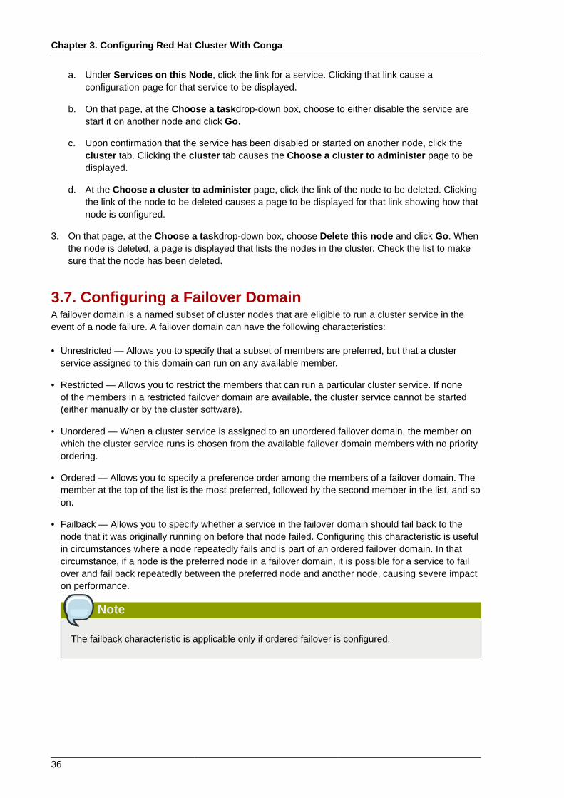
Chapter 3. Configuring Red Hat Cluster With Conga
36
a. Under Services on this Node, click the link for a service. Clicking that link cause aconfiguration page for that service to be displayed.
b. On that page, at the Choose a taskdrop-down box, choose to either disable the service arestart it on another node and click Go.
c. Upon confirmation that the service has been disabled or started on another node, click thecluster tab. Clicking the cluster tab causes the Choose a cluster to administer page to bedisplayed.
d. At the Choose a cluster to administer page, click the link of the node to be deleted. Clickingthe link of the node to be deleted causes a page to be displayed for that link showing how thatnode is configured.
3. On that page, at the Choose a taskdrop-down box, choose Delete this node and click Go. Whenthe node is deleted, a page is displayed that lists the nodes in the cluster. Check the list to makesure that the node has been deleted.
3.7. Configuring a Failover DomainA failover domain is a named subset of cluster nodes that are eligible to run a cluster service in theevent of a node failure. A failover domain can have the following characteristics:
• Unrestricted — Allows you to specify that a subset of members are preferred, but that a clusterservice assigned to this domain can run on any available member.
• Restricted — Allows you to restrict the members that can run a particular cluster service. If noneof the members in a restricted failover domain are available, the cluster service cannot be started(either manually or by the cluster software).
• Unordered — When a cluster service is assigned to an unordered failover domain, the member onwhich the cluster service runs is chosen from the available failover domain members with no priorityordering.
• Ordered — Allows you to specify a preference order among the members of a failover domain. Themember at the top of the list is the most preferred, followed by the second member in the list, and soon.
• Failback — Allows you to specify whether a service in the failover domain should fail back to thenode that it was originally running on before that node failed. Configuring this characteristic is usefulin circumstances where a node repeatedly fails and is part of an ordered failover domain. In thatcircumstance, if a node is the preferred node in a failover domain, it is possible for a service to failover and fail back repeatedly between the preferred node and another node, causing severe impacton performance.
Note
The failback characteristic is applicable only if ordered failover is configured.
Adding a Failover Domain
37
Note
Changing a failover domain configuration has no effect on currently running services.
Note
Failover domains are not required for operation.
By default, failover domains are unrestricted and unordered.
In a cluster with several members, using a restricted failover domain can minimize the work to set upthe cluster to run a cluster service (such as httpd), which requires you to set up the configurationidentically on all members that run the cluster service). Instead of setting up the entire cluster torun the cluster service, you must set up only the members in the restricted failover domain that youassociate with the cluster service.
Note
To configure a preferred member, you can create an unrestricted failover domain comprising onlyone cluster member. Doing that causes a cluster service to run on that cluster member primarily(the preferred member), but allows the cluster service to fail over to any of the other members.
The following sections describe adding a failover domain and modifying a failover domain:
• Section 3.7.1, “Adding a Failover Domain”
• Section 3.7.2, “Modifying a Failover Domain”
3.7.1. Adding a Failover DomainTo add a failover domain, follow the steps in this section. The starting point of the procedure is at thecluster-specific page that you navigate to from Choose a cluster to administer displayed on thecluster tab.
1. At the detailed menu for the cluster (below the clusters menu), click Failover Domains. ClickingFailover Domains causes the display of failover domains with related services and the display ofmenu items for failover domains: Add a Failover Domain and Configure a Failover Domain .
2. Click Add a Failover Domain. Clicking Add a Failover Domain causes the display of the Add aFailover Domain page.
3. At the Add a Failover Domain page, specify a failover domain name at the Failover DomainName text box.
Note
The name should be descriptive enough to distinguish its purpose relative to other namesused in your cluster.
Chapter 3. Configuring Red Hat Cluster With Conga
38
4. To enable setting failover priority of the members in the failover domain, click the Prioritizedcheckbox. With Prioritized checked, you can set the priority value, Priority, for each nodeselected as members of the failover domain.
5. To restrict failover to members in this failover domain, click the checkbox next to Restrict failoverto this domain's members. With Restrict failover to this domain's members checked,services assigned to this failover domain fail over only to nodes in this failover domain.
6. To specify that a node does not fail back in this failover domain, click the checkbox next to Do notfail back services in this domain. With Do not fail back services in this domain checked, if aservice fails over from a preferred node, the service does not fail back to the original node once ithas recovered.
7. Configure members for this failover domain. Under Failover domain membership, click theMember checkbox for each node that is to be a member of the failover domain. If Prioritized ischecked, set the priority in the Priority text box for each member of the failover domain.
8. Click Submit. Clicking Submit causes a progress page to be displayed followed by the displayof the Failover Domain Form page. That page displays the added resource and includes thefailover domain in the cluster menu to the left under Domain.
9. To make additional changes to the failover domain, continue modifications at the Failover DomainForm page and click Submit when you are done.
3.7.2. Modifying a Failover DomainTo modify a failover domain, follow the steps in this section. The starting point of the procedure is atthe cluster-specific page that you navigate to from Choose a cluster to administer displayed on thecluster tab.
1. At the detailed menu for the cluster (below the clusters menu), click Failover Domains. ClickingFailover Domains causes the display of failover domains with related services and the display ofmenu items for failover domains: Add a Failover Domain and Configure a Failover Domain .
2. Click Configure a Failover Domain. Clicking Configure a Failover Domain causes the displayof failover domains under Configure a Failover Domain at the detailed menu for the cluster(below the clusters menu).
3. At the detailed menu for the cluster (below the clusters menu), click the failover domain to modify.Clicking the failover domain causes the display of the Failover Domain Form page. At theFailover Domain Form page, you can modify the failover domain name, prioritize failover, restrictfailover to this domain, and modify failover domain membership.
4. Modifying failover name — To change the failover domain name, modify the text at the FailoverDomain Name text box.
Note
The name should be descriptive enough to distinguish its purpose relative to other namesused in your cluster.
5. Failover priority — To enable or disable prioritized failover in this failover domain, click thePrioritized checkbox. With Prioritized checked, you can set the priority value, Priority, for each
Adding Cluster Resources
39
node selected as members of the failover domain. With Prioritized not checked, setting prioritylevels is disabled for this failover domain.
6. Restricted failover — To enable or disable restricted failover for members in this failover domain,click the checkbox next to Restrict failover to this domain's members. With Restrict failoverto this domain's members checked, services assigned to this failover domain fail over only tonodes in this failover domain. With Restrict failover to this domain's members not checked,services assigned to this failover domain can fail over to nodes outside this failover domain.
7. Failback — To enable or disable failback in a failover domain, click the checkbox next to Do notfail back services in this domain. With Do not fail back services in this domain checked, if aservice fails over from a preferred node, the service does not fail back to the original node once ithas recovered.
8. Modifying failover domain membership — Under Failover domain membership, click theMembercheckbox for each node that is to be a member of the failover domain. A checked box fora node means that the node is a member of the failover domain. If Prioritized is checked, you canadjust the priority in the Priority text box for each member of the failover domain.
9. Click Submit. Clicking Submit causes a progress page to be displayed followed by the displayof the Failover Domain Form page. That page displays the added resource and includes thefailover domain in the cluster menu to the left under Domain.
10. To make additional changes to the failover domain, continue modifications at the Failover DomainForm page and click Submit when you are done.
3.8. Adding Cluster ResourcesTo add a cluster resource, follow the steps in this section. The starting point of the procedure is atthe cluster-specific page that you navigate to from Choose a cluster to administer displayed on thecluster tab.
1. At the detailed menu for the cluster (below the clusters menu), click Resources. ClickingResources causes the display of resources in the center of the page and causes the display ofmenu items for resource configuration: Add a Resource and Configure a Resource.
2. Click Add a Resource. Clicking Add a Resource causes the Add a Resource page to bedisplayed.
3. At the Add a Resource page, click the drop-down box under Select a Resource Type and selectthe type of resource to configure. Appendix C, HA Resource Parameters describes resourceparameters.
4. Click Submit. Clicking Submit causes a progress page to be displayed followed by the displayof Resources forcluster name page. That page displays the added resource (and otherresources).
3.9. Adding a Cluster Service to the ClusterTo add a cluster service to the cluster, follow the steps in this section. The starting point of theprocedure is at the cluster-specific page that you navigate to from Choose a cluster to administerdisplayed on the cluster tab.
1. At the detailed menu for the cluster (below the clusters menu), click Services. Clicking Servicescauses the display of services in the center of the page and causes the display of menu items forservices configuration: Add a Service and Configure a Service.
Chapter 3. Configuring Red Hat Cluster With Conga
40
2. Click Add a Service. Clicking Add a Service causes the Add a Service page to be displayed.
3. On the Add a Service page, at the Service name text box, type the name of the service.Below the Service name text box is an checkbox labeled Automatically start this service.The checkbox is checked by default. When the checkbox is checked, the service is startedautomatically when a cluster is started and running. If the checkbox is not checked, the servicemust be started manually any time the cluster comes up from the stopped state.
Note
Use a descriptive name that clearly distinguishes the service from other services in thecluster.
4. Add a resource to the service; click Add a resource to this service. Clicking Add a resourceto this service causes the display of two drop-down boxes: Add a new local resource and Usean existing global resource. Adding a new local resource adds a resource that is available onlyto this service. The process of adding a local resource is the same as adding a global resourcedescribed in Section 3.8, “Adding Cluster Resources”. Adding a global resource adds a resourcethat has been previously added as a global resource (refer to Section 3.8, “Adding ClusterResources”).
5. At the drop-down box of either Add a new local resource or Use an existing global resource,select the resource to add and configure it according to the options presented. (The options arethe same as described in Section 3.8, “Adding Cluster Resources”.)
Note
If you are adding a Samba-service resource, connect a Samba-service resource directly tothe service, not to a resource within a service.
6. If you want to add resources to that resource, click Add a child. Clicking Add a child causesthe display of additional options to local and global resources. You can continue adding childrenresources to the resource to suit your requirements. To view children resources, click the triangleicon to the left of Show Children.
7. When you have completed adding resources to the service, and have completed adding childrenresources to resources, click Submit. Clicking Submit causes a progress page to be displayedfollowed by a page displaying the added service (and other services).
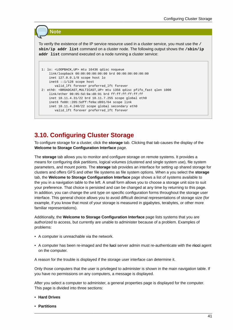
Configuring Cluster Storage
41
Note
To verify the existence of the IP service resource used in a cluster service, you must use the /sbin/ip addr list command on a cluster node. The following output shows the /sbin/ipaddr list command executed on a node running a cluster service:
1: lo: <LOOPBACK,UP> mtu 16436 qdisc noqueue link/loopback 00:00:00:00:00:00 brd 00:00:00:00:00:00 inet 127.0.0.1/8 scope host lo inet6 ::1/128 scope host valid_lft forever preferred_lft forever2: eth0: <BROADCAST,MULTICAST,UP> mtu 1356 qdisc pfifo_fast qlen 1000 link/ether 00:05:5d:9a:d8:91 brd ff:ff:ff:ff:ff:ff inet 10.11.4.31/22 brd 10.11.7.255 scope global eth0 inet6 fe80::205:5dff:fe9a:d891/64 scope link inet 10.11.4.240/22 scope global secondary eth0 valid_lft forever preferred_lft forever
3.10. Configuring Cluster StorageTo configure storage for a cluster, click the storage tab. Clicking that tab causes the display of theWelcome to Storage Configuration Interface page.
The storage tab allows you to monitor and configure storage on remote systems. It provides ameans for configuring disk partitions, logical volumes (clustered and single system use), file systemparameters, and mount points. The storage tab provides an interface for setting up shared storage forclusters and offers GFS and other file systems as file system options. When a you select the storagetab, the Welcome to Storage Configuration Interface page shows a list of systems available tothe you in a navigation table to the left. A small form allows you to choose a storage unit size to suityour preference. That choice is persisted and can be changed at any time by returning to this page.In addition, you can change the unit type on specific configuration forms throughout the storage userinterface. This general choice allows you to avoid difficult decimal representations of storage size (forexample, if you know that most of your storage is measured in gigabytes, terabytes, or other morefamiliar representations).
Additionally, the Welcome to Storage Configuration Interface page lists systems that you areauthorized to access, but currently are unable to administer because of a problem. Examples ofproblems:
• A computer is unreachable via the network.
• A computer has been re-imaged and the luci server admin must re-authenticate with the ricci agenton the computer.
A reason for the trouble is displayed if the storage user interface can determine it.
Only those computers that the user is privileged to administer is shown in the main navigation table. Ifyou have no permissions on any computers, a message is displayed.
After you select a computer to administer, a general properties page is displayed for the computer.This page is divided into three sections:
• Hard Drives
• Partitions
Chapter 3. Configuring Red Hat Cluster With Conga
42
• Volume Groups
Each section is set up as an expandable tree, with links to property sheets for specific devices,partitions, and storage entities.
Configure the storage for your cluster to suit your cluster requirements. If you are configuring Red HatGFS, configure clustered logical volumes first, using CLVM. For more information about CLVM andGFS refer to Red Hat documentation for those products.
Note
Shared storage for use in Red Hat Cluster Suite requires that you be running the cluster logicalvolume manager daemon (clvmd) or the High Availability Logical Volume Management agents(HA-LVM). If you are not able to use either the clvmd daemon or HA-LVM for operationalreasons or because you do not have the correct entitlements, you must not use single-instanceLVM on the shared disk as this may result in data corruption. If you have any concerns pleasecontact your Red Hat service representative.
Chapter 4.
43
Managing Red Hat Cluster With CongaThis chapter describes various administrative tasks for managing a Red Hat Cluster and consists ofthe following sections:
• Section 4.1, “Starting, Stopping, and Deleting Clusters”
• Section 4.2, “Managing Cluster Nodes”
• Section 4.3, “Managing High-Availability Services”
• Section 4.4, “Diagnosing and Correcting Problems in a Cluster”
4.1. Starting, Stopping, and Deleting ClustersYou can perform the following cluster-management functions through the luci server component ofConga:
• Restart a cluster.
• Start a cluster.
• Stop a cluster.
• Delete a cluster.
To perform one of the functions in the preceding list, follow the steps in this section. The starting pointof the procedure is at the cluster tab (at the Choose a cluster to administer page).
1. At the right of the Cluster Name for each cluster listed on the Choose a cluster to administerpage is a drop-down box. By default, the drop-down box is set to Restart this cluster. Clickingthe drop-down box box reveals all the selections available: Restart this cluster, Stop thiscluster/Start this cluster, and Delete this cluster. The actions of each function are summarizedas follows:
• Restart this cluster — Selecting this action causes the cluster to be restarted. You can selectthis action for any state the cluster is in.
• Stop this cluster/Start this cluster — Stop this cluster is available when a cluster is running.Start this cluster is available when a cluster is stopped.
Selecting Stop this cluster shuts down cluster software in all cluster nodes.
Selecting Start this cluster starts cluster software.
• Delete this cluster — Selecting this action halts a running cluster, disables cluster softwarefrom starting automatically, and removes the cluster configuration file from each node. You canselect this action for any state the cluster is in. Deleting a cluster frees each node in the clusterfor use in another cluster.
2. Select one of the functions and click Go.
3. Clicking Go causes a progress page to be displayed. When the action is complete, a page isdisplayed showing either of the following pages according to the action selected:
• For Restart this cluster and Stop this cluster/Start this cluster — Displays a page with thelist of nodes for the cluster.
Chapter 4. Managing Red Hat Cluster With Conga
44
• For Delete this cluster — Displays the Choose a cluster to administer page in the clustertab, showing a list of clusters.
4.2. Managing Cluster NodesYou can perform the following node-management functions through the luci server component ofConga:
• Make a node leave or join a cluster.
• Fence a node.
• Reboot a node.
• Delete a node.
To perform one the functions in the preceding list, follow the steps in this section. The starting pointof the procedure is at the cluster-specific page that you navigate to from Choose a cluster toadminister displayed on the cluster tab.
1. At the detailed menu for the cluster (below the clusters menu), click Nodes. Clicking Nodescauses the display of nodes in the center of the page and causes the display of an Add a Nodeelement and a Configure element with a list of the nodes already configured in the cluster.
2. At the right of each node listed on the page displayed from the preceding step, click the Choosea task drop-down box. Clicking Choose a task drop-down box reveals the following selections:Have node leave cluster/Have node join cluster, Fence this node, Reboot this node, andDelete. The actions of each function are summarized as follows:
• Have node leave cluster/Have node join cluster — Have node leave cluster is availablewhen a node has joined of a cluster. Have node join cluster is available when a node has left acluster.
Selecting Have node leave cluster shuts down cluster software and makes the node leave thecluster. Making a node leave a cluster prevents the node from automatically joining the clusterwhen it is rebooted.
Selecting Have node join cluster starts cluster software and makes the node join the cluster.Making a node join a cluster allows the node to automatically join the cluster when it is rebooted.
• Fence this node — Selecting this action causes the node to be fenced according to how thenode is configured to be fenced.
• Reboot this node — Selecting this action causes the node to be rebooted.
• Delete — Selecting this action causes the node to be deleted from the cluster configuration.It also stops all cluster services on the node, and deletes the cluster.conf file from /etc/cluster/.
3. Select one of the functions and click Go.
4. Clicking Go causes a progress page to be displayed. When the action is complete, a page isdisplayed showing the list of nodes for the cluster.
Managing High-Availability Services
45
4.3. Managing High-Availability ServicesYou can perform the following management functions for high-availability services through the luciserver component of Conga:
• Configure a service.
• Stop or start a service.
• Restart a service.
• Delete a service
To perform one the functions in the preceding list, follow the steps in this section. The starting pointof the procedure is at the cluster-specific page that you navigate to from Choose a cluster toadminister displayed on the cluster tab.
1. At the detailed menu for the cluster (below the clusters menu), click Services. Clicking Servicescauses the display of services for the cluster in the center of the page.
2. At the right of each service listed on the page, click the Choose a task drop-down box. ClickingChoose a task drop-down box reveals the following selections depending on if the service isrunning:
• If service is running — Configure this service, Restart this service, and Stop this service.
• If service is not running — Configure this service, Start this service, and Delete this service.
The actions of each function are summarized as follows:
• Configure this service — Configure this service is available when the service is runningor not running. Selecting Configure this service causes the services configuration page forthe service to be displayed. On that page, you can change the configuration of the service. Forexample, you can add a resource to the service. (For more information about adding resourcesand services, refer toSection 3.8, “Adding Cluster Resources” and Section 3.9, “Adding aCluster Service to the Cluster”.) In addition, a drop-down box on the page provides otherfunctions depending on if the service is running.
When a service is running, the drop-down box provides the following functions: restarting,disabling, and relocating the service.
When a service is not running, the drop-down box on the configuration page provides thefollowing functions: enabling and deleting the service.
If you are making configuration changes, save the changes by clicking Save. Clicking Savecauses a progress page to be displayed. When the change is complete, another page isdisplayed showing a list of services for the cluster.
If you have selected one of the functions in the drop-down box on the configuration page,click Go. Clicking Go causes a progress page to be displayed. When the change is complete,another page is displayed showing a list of services for the cluster.
• Restart this service and Stop this service — These selections are available when theservice is running. Select either function and click Go to make the change take effect. ClickingGo causes a progress page to be displayed. When the change is complete, another page isdisplayed showing a list of services for the cluster.

Chapter 4. Managing Red Hat Cluster With Conga
46
• Start this service and Delete this service — These selections are available when the serviceis not running. Select either function and click Go to make the change take effect. ClickingGo causes a progress page to be displayed. When the change is complete, another page isdisplayed showing a list of services for the cluster.
4.4. Diagnosing and Correcting Problems in a ClusterFor information about diagnosing and correcting problems in a cluster, contact an authorized Red Hatsupport representative.
Chapter 5.
47
Configuring Red Hat Cluster Withsystem-config-clusterThis chapter describes how to configure Red Hat Cluster software using system-config-cluster,and consists of the following sections:
• Section 5.1, “Configuration Tasks”
• Section 5.2, “Starting the Cluster Configuration Tool”
• Section 5.3, “Configuring Cluster Properties”
• Section 5.4, “Configuring Fence Devices”
• Section 5.5, “Adding and Deleting Members”
• Section 5.6, “Configuring a Failover Domain”
• Section 5.7, “Adding Cluster Resources”
• Section 5.8, “Adding a Cluster Service to the Cluster”
• Section 5.9, “Propagating The Configuration File: New Cluster”
• Section 5.10, “Starting the Cluster Software”
Note
While system-config-cluster provides several convenient tools for configuring andmanaging a Red Hat Cluster, the newer, more comprehensive tool, Conga, provides moreconvenience and flexibility than system-config-cluster. You may want to consider usingConga instead (refer to Chapter 3, Configuring Red Hat Cluster With Conga and Chapter 4,Managing Red Hat Cluster With Conga).
5.1. Configuration TasksConfiguring Red Hat Cluster software with system-config-cluster consists of the following steps:
1. Starting the Cluster Configuration Tool, system-config-cluster. Refer to Section 5.2,“Starting the Cluster Configuration Tool”.
2. Configuring cluster properties. Refer to Section 5.3, “Configuring Cluster Properties”.
3. Creating fence devices. Refer to Section 5.4, “Configuring Fence Devices”.
4. Creating cluster members. Refer to Section 5.5, “Adding and Deleting Members”.
5. Creating failover domains. Refer to Section 5.6, “Configuring a Failover Domain”.
6. Creating resources. Refer to Section 5.7, “Adding Cluster Resources”.
7. Creating cluster services.
Refer to Section 5.8, “Adding a Cluster Service to the Cluster”.
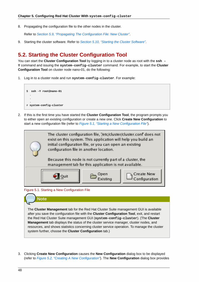
Chapter 5. Configuring Red Hat Cluster With system-config-cluster
48
8. Propagating the configuration file to the other nodes in the cluster.
Refer to Section 5.9, “Propagating The Configuration File: New Cluster”.
9. Starting the cluster software. Refer to Section 5.10, “Starting the Cluster Software”.
5.2. Starting the Cluster Configuration ToolYou can start the Cluster Configuration Tool by logging in to a cluster node as root with the ssh -Y command and issuing the system-config-cluster command. For example, to start the ClusterConfiguration Tool on cluster node nano-01, do the following:
1. Log in to a cluster node and run system-config-cluster. For example:
$ ssh -Y root@nano-01 . . .# system-config-cluster
2. If this is the first time you have started the Cluster Configuration Tool, the program prompts youto either open an existing configuration or create a new one. Click Create New Configuration tostart a new configuration file (refer to Figure 5.1, “Starting a New Configuration File”).
Figure 5.1. Starting a New Configuration File
Note
The Cluster Management tab for the Red Hat Cluster Suite management GUI is availableafter you save the configuration file with the Cluster Configuration Tool, exit, and restartthe Red Hat Cluster Suite management GUI (system-config-cluster). (The ClusterManagement tab displays the status of the cluster service manager, cluster nodes, andresources, and shows statistics concerning cluster service operation. To manage the clustersystem further, choose the Cluster Configuration tab.)
3. Clicking Create New Configuration causes the New Configuration dialog box to be displayed(refer to Figure 5.2, “Creating A New Configuration”). The New Configuration dialog box provides
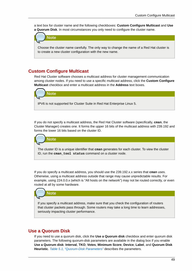
Custom Configure Multicast
49
a text box for cluster name and the following checkboxes: Custom Configure Multicast and Usea Quorum Disk. In most circumstances you only need to configure the cluster name.
Note
Choose the cluster name carefully. The only way to change the name of a Red Hat cluster isto create a new cluster configuration with the new name.
Custom Configure MulticastRed Hat Cluster software chooses a multicast address for cluster management communicationamong cluster nodes. If you need to use a specific multicast address, click the Custom ConfigureMulticast checkbox and enter a multicast address in the Address text boxes.
Note
IPV6 is not supported for Cluster Suite in Red Hat Enterprise Linux 5.
If you do not specify a multicast address, the Red Hat Cluster software (specifically, cman, theCluster Manager) creates one. It forms the upper 16 bits of the multicast address with 239.192 andforms the lower 16 bits based on the cluster ID.
Note
The cluster ID is a unique identifier that cman generates for each cluster. To view the clusterID, run the cman_tool status command on a cluster node.
If you do specify a multicast address, you should use the 239.192.x.x series that cman uses.Otherwise, using a multicast address outside that range may cause unpredictable results. Forexample, using 224.0.0.x (which is "All hosts on the network") may not be routed correctly, or evenrouted at all by some hardware.
Note
If you specify a multicast address, make sure that you check the configuration of routersthat cluster packets pass through. Some routers may take a long time to learn addresses,seriously impacting cluster performance.
Use a Quorum DiskIf you need to use a quorum disk, click the Use a Quorum disk checkbox and enter quorum diskparameters. The following quorum-disk parameters are available in the dialog box if you enableUse a Quorum disk: Interval, TKO, Votes, Minimum Score, Device, Label, and Quorum DiskHeuristic. Table 5.1, “Quorum-Disk Parameters” describes the parameters.
Chapter 5. Configuring Red Hat Cluster With system-config-cluster
50
Important
Quorum-disk parameters and heuristics depend on the site environment and specialrequirements needed. To understand the use of quorum-disk parameters and heuristics, referto the qdisk(5) man page. If you require assistance understanding and using quorum disk,contact an authorized Red Hat support representative.
Note
It is probable that configuring a quorum disk requires changing quorum-disk parametersafter the initial configuration. The Cluster Configuration Tool (system-config-cluster)provides only the display of quorum-disk parameters after initial configuration. If you need toconfigure quorum disk, consider using Conga instead; Conga allows modification of quorumdisk parameters.
Overall:
While system-config-cluster provides several convenient tools for configuring andmanaging a Red Hat Cluster, the newer, more comprehensive tool, Conga, provides moreconvenience and flexibility than system-config-cluster. You may want to consider usingConga instead (refer to Chapter 3, Configuring Red Hat Cluster With Conga and Chapter 4,Managing Red Hat Cluster With Conga).
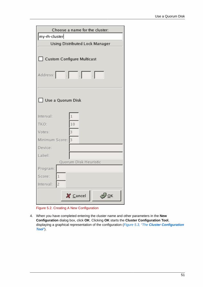
Use a Quorum Disk
51
Figure 5.2. Creating A New Configuration
4. When you have completed entering the cluster name and other parameters in the NewConfiguration dialog box, click OK. Clicking OK starts the Cluster Configuration Tool,displaying a graphical representation of the configuration (Figure 5.3, “The Cluster ConfigurationTool”).
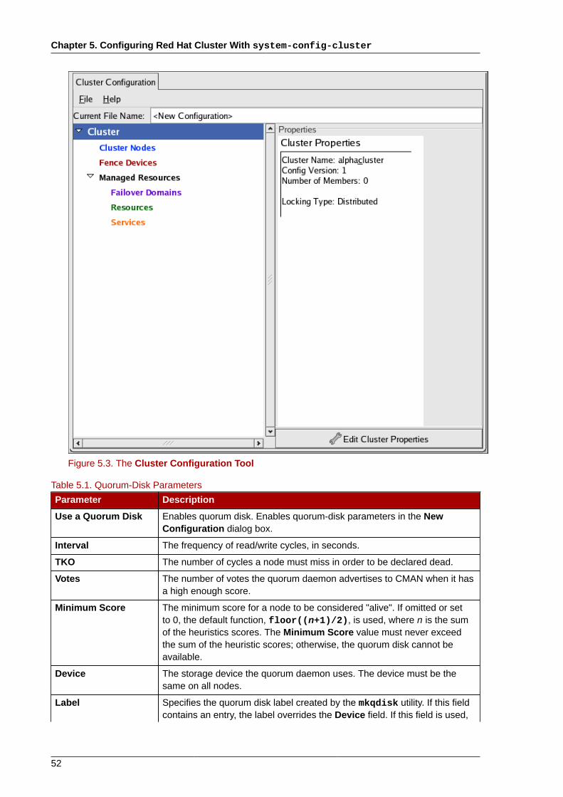
Chapter 5. Configuring Red Hat Cluster With system-config-cluster
52
Figure 5.3. The Cluster Configuration Tool
Table 5.1. Quorum-Disk Parameters
Parameter Description
Use a Quorum Disk Enables quorum disk. Enables quorum-disk parameters in the NewConfiguration dialog box.
Interval The frequency of read/write cycles, in seconds.
TKO The number of cycles a node must miss in order to be declared dead.
Votes The number of votes the quorum daemon advertises to CMAN when it hasa high enough score.
Minimum Score The minimum score for a node to be considered "alive". If omitted or setto 0, the default function, floor((n+1)/2), is used, where n is the sumof the heuristics scores. The Minimum Score value must never exceedthe sum of the heuristic scores; otherwise, the quorum disk cannot beavailable.
Device The storage device the quorum daemon uses. The device must be thesame on all nodes.
Label Specifies the quorum disk label created by the mkqdisk utility. If this fieldcontains an entry, the label overrides the Device field. If this field is used,
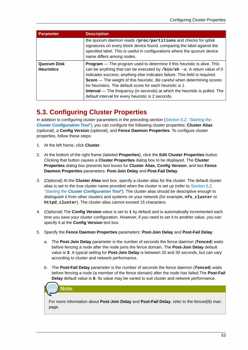
Configuring Cluster Properties
53
Parameter Descriptionthe quorum daemon reads /proc/partitions and checks for qdisksignatures on every block device found, comparing the label against thespecified label. This is useful in configurations where the quorum devicename differs among nodes.
Quorum DiskHeuristics
Program — The program used to determine if this heuristic is alive. Thiscan be anything that can be executed by /bin/sh -c. A return value of 0indicates success; anything else indicates failure. This field is required.Score — The weight of this heuristic. Be careful when determining scoresfor heuristics. The default score for each heuristic is 1.Interval — The frequency (in seconds) at which the heuristic is polled. Thedefault interval for every heuristic is 2 seconds.
5.3. Configuring Cluster PropertiesIn addition to configuring cluster parameters in the preceding section (Section 5.2, “Starting theCluster Configuration Tool”), you can configure the following cluster properties: Cluster Alias(optional), a Config Version (optional), and Fence Daemon Properties. To configure clusterproperties, follow these steps:
1. At the left frame, click Cluster.
2. At the bottom of the right frame (labeled Properties), click the Edit Cluster Properties button.Clicking that button causes a Cluster Properties dialog box to be displayed. The ClusterProperties dialog box presents text boxes for Cluster Alias, Config Version, and two FenceDaemon Properties parameters: Post-Join Delay and Post-Fail Delay.
3. (Optional) At the Cluster Alias text box, specify a cluster alias for the cluster. The default clusteralias is set to the true cluster name provided when the cluster is set up (refer to Section 5.2,“Starting the Cluster Configuration Tool”). The cluster alias should be descriptive enough todistinguish it from other clusters and systems on your network (for example, nfs_cluster orhttpd_cluster). The cluster alias cannot exceed 15 characters.
4. (Optional) The Config Version value is set to 1 by default and is automatically incremented eachtime you save your cluster configuration. However, if you need to set it to another value, you canspecify it at the Config Version text box.
5. Specify the Fence Daemon Properties parameters: Post-Join Delay and Post-Fail Delay.
a. The Post-Join Delay parameter is the number of seconds the fence daemon (fenced) waitsbefore fencing a node after the node joins the fence domain. The Post-Join Delay defaultvalue is 3. A typical setting for Post-Join Delay is between 20 and 30 seconds, but can varyaccording to cluster and network performance.
b. The Post-Fail Delay parameter is the number of seconds the fence daemon (fenced) waitsbefore fencing a node (a member of the fence domain) after the node has failed.The Post-FailDelay default value is 0. Its value may be varied to suit cluster and network performance.
Note
For more information about Post-Join Delay and Post-Fail Delay, refer to the fenced(8) manpage.
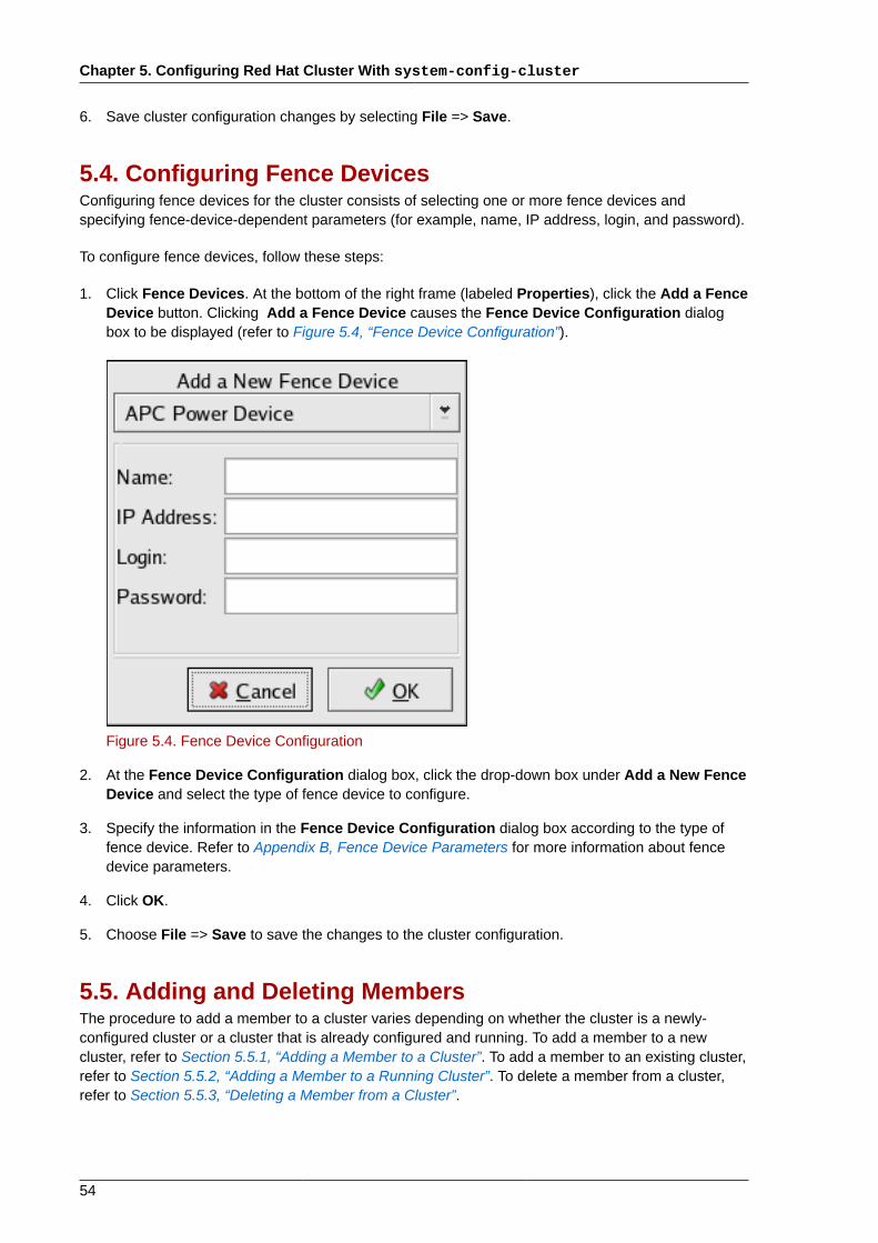
Chapter 5. Configuring Red Hat Cluster With system-config-cluster
54
6. Save cluster configuration changes by selecting File => Save.
5.4. Configuring Fence DevicesConfiguring fence devices for the cluster consists of selecting one or more fence devices andspecifying fence-device-dependent parameters (for example, name, IP address, login, and password).
To configure fence devices, follow these steps:
1. Click Fence Devices. At the bottom of the right frame (labeled Properties), click the Add a FenceDevice button. Clicking Add a Fence Device causes the Fence Device Configuration dialogbox to be displayed (refer to Figure 5.4, “Fence Device Configuration”).
Figure 5.4. Fence Device Configuration
2. At the Fence Device Configuration dialog box, click the drop-down box under Add a New FenceDevice and select the type of fence device to configure.
3. Specify the information in the Fence Device Configuration dialog box according to the type offence device. Refer to Appendix B, Fence Device Parameters for more information about fencedevice parameters.
4. Click OK.
5. Choose File => Save to save the changes to the cluster configuration.
5.5. Adding and Deleting MembersThe procedure to add a member to a cluster varies depending on whether the cluster is a newly-configured cluster or a cluster that is already configured and running. To add a member to a newcluster, refer to Section 5.5.1, “Adding a Member to a Cluster”. To add a member to an existing cluster,refer to Section 5.5.2, “Adding a Member to a Running Cluster”. To delete a member from a cluster,refer to Section 5.5.3, “Deleting a Member from a Cluster”.
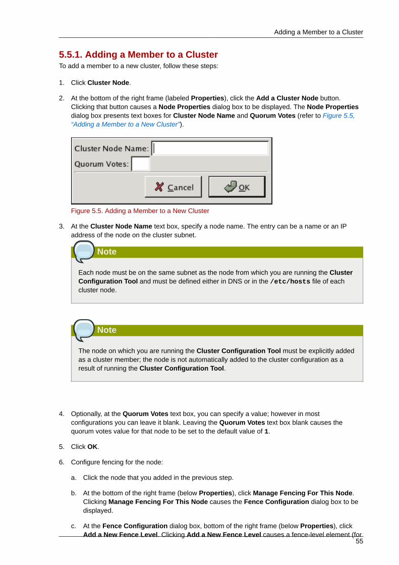
Adding a Member to a Cluster
55
5.5.1. Adding a Member to a ClusterTo add a member to a new cluster, follow these steps:
1. Click Cluster Node.
2. At the bottom of the right frame (labeled Properties), click the Add a Cluster Node button.Clicking that button causes a Node Properties dialog box to be displayed. The Node Propertiesdialog box presents text boxes for Cluster Node Name and Quorum Votes (refer to Figure 5.5,“Adding a Member to a New Cluster”).
Figure 5.5. Adding a Member to a New Cluster
3. At the Cluster Node Name text box, specify a node name. The entry can be a name or an IPaddress of the node on the cluster subnet.
Note
Each node must be on the same subnet as the node from which you are running the ClusterConfiguration Tool and must be defined either in DNS or in the /etc/hosts file of eachcluster node.
Note
The node on which you are running the Cluster Configuration Tool must be explicitly addedas a cluster member; the node is not automatically added to the cluster configuration as aresult of running the Cluster Configuration Tool.
4. Optionally, at the Quorum Votes text box, you can specify a value; however in mostconfigurations you can leave it blank. Leaving the Quorum Votes text box blank causes thequorum votes value for that node to be set to the default value of 1.
5. Click OK.
6. Configure fencing for the node:
a. Click the node that you added in the previous step.
b. At the bottom of the right frame (below Properties), click Manage Fencing For This Node.Clicking Manage Fencing For This Node causes the Fence Configuration dialog box to bedisplayed.
c. At the Fence Configuration dialog box, bottom of the right frame (below Properties), clickAdd a New Fence Level. Clicking Add a New Fence Level causes a fence-level element (for
Chapter 5. Configuring Red Hat Cluster With system-config-cluster
56
example, Fence-Level-1, Fence-Level-2, and so on) to be displayed below the node in theleft frame of the Fence Configuration dialog box.
d. Click the fence-level element.
e. At the bottom of the right frame (below Properties), click Add a New Fence to this Level.Clicking Add a New Fence to this Level causes the Fence Properties dialog box to bedisplayed.
f. At the Fence Properties dialog box, click the Fence Device Type drop-down box and selectthe fence device for this node. Also, provide additional information required (for example, Portand Switch for an APC Power Device).
g. At the Fence Properties dialog box, click OK. Clicking OK causes a fence device element tobe displayed below the fence-level element.
h. To create additional fence devices at this fence level, return to step 6d. Otherwise, proceed tothe next step.
i. To create additional fence levels, return to step 6c. Otherwise, proceed to the next step.
j. If you have configured all the fence levels and fence devices for this node, click Close.
7. Choose File => Save to save the changes to the cluster configuration.
5.5.2. Adding a Member to a Running ClusterThe procedure for adding a member to a running cluster depends on whether the cluster contains onlytwo nodes or more than two nodes. To add a member to a running cluster, follow the steps in one ofthe following sections according to the number of nodes in the cluster:
• For clusters with only two nodes —
Section 5.5.2.1, “Adding a Member to a Running Cluster That Contains Only Two Nodes”
• For clusters with more than two nodes —
Section 5.5.2.2, “Adding a Member to a Running Cluster That Contains More Than Two Nodes”
5.5.2.1. Adding a Member to a Running Cluster That Contains Only TwoNodesTo add a member to an existing cluster that is currently in operation, and contains only two nodes,follow these steps:
1. Add the node and configure fencing for it as in
Section 5.5.1, “Adding a Member to a Cluster”.
2. Click Send to Cluster to propagate the updated configuration to other running nodes in thecluster.
3. Use the scp command to send the updated /etc/cluster/cluster.conf file from one of theexisting cluster nodes to the new node.
4. At the Red Hat Cluster Suite management GUI Cluster Status Tool tab, disable each servicelisted under Services.
Adding a Member to a Running Cluster
57
5. Stop the cluster software on the two running nodes by running the following commands at eachnode in this order:
a. service rgmanager stop
b. service gfs stop, if you are using Red Hat GFS
c. service clvmd stop, if CLVM has been used to create clustered volumes
d. service cman stop
6. Start cluster software on all cluster nodes (including the added one) by running the followingcommands in this order:
a. service cman start
b. service clvmd start, if CLVM has been used to create clustered volumes
c. service gfs start, if you are using Red Hat GFS
d. service rgmanager start
7. Start the Red Hat Cluster Suite management GUI. At the Cluster Configuration Tool tab, verifythat the configuration is correct. At the Cluster Status Tool tab verify that the nodes and servicesare running as expected.
5.5.2.2. Adding a Member to a Running Cluster That Contains More ThanTwo NodesTo add a member to an existing cluster that is currently in operation, and contains more than twonodes, follow these steps:
1. Add the node and configure fencing for it as in
Section 5.5.1, “Adding a Member to a Cluster”.
2. Click Send to Cluster to propagate the updated configuration to other running nodes in thecluster.
3. Use the scp command to send the updated /etc/cluster/cluster.conf file from one of theexisting cluster nodes to the new node.
4. Start cluster services on the new node by running the following commands in this order:
a. service cman start
b. service clvmd start, if CLVM has been used to create clustered volumes
c. service gfs start, if you are using Red Hat GFS
d. service rgmanager start
5. Start the Red Hat Cluster Suite management GUI. At the Cluster Configuration Tool tab, verifythat the configuration is correct. At the Cluster Status Tool tab verify that the nodes and servicesare running as expected.
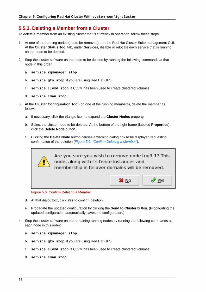
Chapter 5. Configuring Red Hat Cluster With system-config-cluster
58
5.5.3. Deleting a Member from a ClusterTo delete a member from an existing cluster that is currently in operation, follow these steps:
1. At one of the running nodes (not to be removed), run the Red Hat Cluster Suite management GUI.At the Cluster Status Tool tab, under Services, disable or relocate each service that is runningon the node to be deleted.
2. Stop the cluster software on the node to be deleted by running the following commands at thatnode in this order:
a. service rgmanager stop
b. service gfs stop, if you are using Red Hat GFS
c. service clvmd stop, if CLVM has been used to create clustered volumes
d. service cman stop
3. At the Cluster Configuration Tool (on one of the running members), delete the member asfollows:
a. If necessary, click the triangle icon to expand the Cluster Nodes property.
b. Select the cluster node to be deleted. At the bottom of the right frame (labeled Properties),click the Delete Node button.
c. Clicking the Delete Node button causes a warning dialog box to be displayed requestingconfirmation of the deletion (Figure 5.6, “Confirm Deleting a Member”).
Figure 5.6. Confirm Deleting a Member
d. At that dialog box, click Yes to confirm deletion.
e. Propagate the updated configuration by clicking the Send to Cluster button. (Propagating theupdated configuration automatically saves the configuration.)
4. Stop the cluster software on the remaining running nodes by running the following commands ateach node in this order:
a. service rgmanager stop
b. service gfs stop, if you are using Red Hat GFS
c. service clvmd stop, if CLVM has been used to create clustered volumes
d. service cman stop
Configuring a Failover Domain
59
5. Start cluster software on all remaining cluster nodes by running the following commands in thisorder:
a. service cman start
b. service clvmd start, if CLVM has been used to create clustered volumes
c. service gfs start, if you are using Red Hat GFS
d. service rgmanager start
6. Start the Red Hat Cluster Suite management GUI. At the Cluster Configuration Tool tab, verifythat the configuration is correct. At the Cluster Status Tool tab verify that the nodes and servicesare running as expected.
5.6. Configuring a Failover DomainA failover domain is a named subset of cluster nodes that are eligible to run a cluster service in theevent of a node failure. A failover domain can have the following characteristics:
• Unrestricted — Allows you to specify that a subset of members are preferred, but that a clusterservice assigned to this domain can run on any available member.
• Restricted — Allows you to restrict the members that can run a particular cluster service. If noneof the members in a restricted failover domain are available, the cluster service cannot be started(either manually or by the cluster software).
• Unordered — When a cluster service is assigned to an unordered failover domain, the member onwhich the cluster service runs is chosen from the available failover domain members with no priorityordering.
• Ordered — Allows you to specify a preference order among the members of a failover domain. Themember at the top of the list is the most preferred, followed by the second member in the list, and soon.
Note
Changing a failover domain configuration has no effect on currently running services.
Note
Failover domains are not required for operation.
By default, failover domains are unrestricted and unordered.
In a cluster with several members, using a restricted failover domain can minimize the work to set upthe cluster to run a cluster service (such as httpd), which requires you to set up the configurationidentically on all members that run the cluster service). Instead of setting up the entire cluster torun the cluster service, you must set up only the members in the restricted failover domain that youassociate with the cluster service.
Chapter 5. Configuring Red Hat Cluster With system-config-cluster
60
Note
To configure a preferred member, you can create an unrestricted failover domain comprising onlyone cluster member. Doing that causes a cluster service to run on that cluster member primarily(the preferred member), but allows the cluster service to fail over to any of the other members.
The following sections describe adding a failover domain, removing a failover domain, and removingmembers from a failover domain:
• Section 5.6.1, “Adding a Failover Domain”
• Section 5.6.2, “Removing a Failover Domain”
• Section 5.6.3, “Removing a Member from a Failover Domain”
5.6.1. Adding a Failover DomainTo add a failover domain, follow these steps:
1. At the left frame of the Cluster Configuration Tool, click Failover Domains.
2. At the bottom of the right frame (labeled Properties), click the Create a Failover Domain button.Clicking the Create a Failover Domain button causes the Add Failover Domain dialog box to bedisplayed.
3. At the Add Failover Domain dialog box, specify a failover domain name at the Name for newFailover Domain text box and click OK. Clicking OK causes the Failover Domain Configurationdialog box to be displayed (Figure 5.7, “Failover Domain Configuration: Configuring a FailoverDomain”).
Note
The name should be descriptive enough to distinguish its purpose relative to other namesused in your cluster.
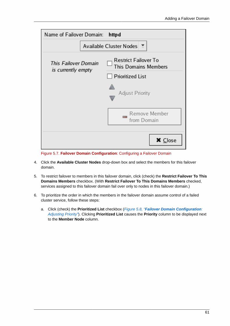
Adding a Failover Domain
61
Figure 5.7. Failover Domain Configuration: Configuring a Failover Domain
4. Click the Available Cluster Nodes drop-down box and select the members for this failoverdomain.
5. To restrict failover to members in this failover domain, click (check) the Restrict Failover To ThisDomains Members checkbox. (With Restrict Failover To This Domains Members checked,services assigned to this failover domain fail over only to nodes in this failover domain.)
6. To prioritize the order in which the members in the failover domain assume control of a failedcluster service, follow these steps:
a. Click (check) the Prioritized List checkbox (Figure 5.8, “Failover Domain Configuration:Adjusting Priority”). Clicking Prioritized List causes the Priority column to be displayed nextto the Member Node column.
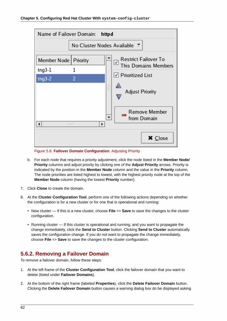
Chapter 5. Configuring Red Hat Cluster With system-config-cluster
62
Figure 5.8. Failover Domain Configuration: Adjusting Priority
b. For each node that requires a priority adjustment, click the node listed in the Member Node/Priority columns and adjust priority by clicking one of the Adjust Priority arrows. Priority isindicated by the position in the Member Node column and the value in the Priority column.The node priorities are listed highest to lowest, with the highest priority node at the top of theMember Node column (having the lowest Priority number).
7. Click Close to create the domain.
8. At the Cluster Configuration Tool, perform one of the following actions depending on whetherthe configuration is for a new cluster or for one that is operational and running:
• New cluster — If this is a new cluster, choose File => Save to save the changes to the clusterconfiguration.
• Running cluster — If this cluster is operational and running, and you want to propagate thechange immediately, click the Send to Cluster button. Clicking Send to Cluster automaticallysaves the configuration change. If you do not want to propagate the change immediately,choose File => Save to save the changes to the cluster configuration.
5.6.2. Removing a Failover DomainTo remove a failover domain, follow these steps:
1. At the left frame of the Cluster Configuration Tool, click the failover domain that you want todelete (listed under Failover Domains).
2. At the bottom of the right frame (labeled Properties), click the Delete Failover Domain button.Clicking the Delete Failover Domain button causes a warning dialog box do be displayed asking
Removing a Member from a Failover Domain
63
if you want to remove the failover domain. Confirm that the failover domain identified in thewarning dialog box is the one you want to delete and click Yes. Clicking Yes causes the failoverdomain to be removed from the list of failover domains under Failover Domains in the left frameof the Cluster Configuration Tool.
3. At the Cluster Configuration Tool, perform one of the following actions depending on whetherthe configuration is for a new cluster or for one that is operational and running:
• New cluster — If this is a new cluster, choose File => Save to save the changes to the clusterconfiguration.
• Running cluster — If this cluster is operational and running, and you want to propagate thechange immediately, click the Send to Cluster button. Clicking Send to Cluster automaticallysaves the configuration change. If you do not want to propagate the change immediately,choose File => Save to save the changes to the cluster configuration.
5.6.3. Removing a Member from a Failover DomainTo remove a member from a failover domain, follow these steps:
1. At the left frame of the Cluster Configuration Tool, click the failover domain that you want tochange (listed under Failover Domains).
2. At the bottom of the right frame (labeled Properties), click the Edit Failover Domain Propertiesbutton. Clicking the Edit Failover Domain Properties button causes the Failover DomainConfiguration dialog box to be displayed (Figure 5.7, “Failover Domain Configuration:Configuring a Failover Domain”).
3. At the Failover Domain Configuration dialog box, in the Member Node column, click the nodename that you want to delete from the failover domain and click the Remove Member fromDomain button. Clicking Remove Member from Domain removes the node from the MemberNode column. Repeat this step for each node that is to be deleted from the failover domain.(Nodes must be deleted one at a time.)
4. When finished, click Close.
5. At the Cluster Configuration Tool, perform one of the following actions depending on whetherthe configuration is for a new cluster or for one that is operational and running:
• New cluster — If this is a new cluster, choose File => Save to save the changes to the clusterconfiguration.
• Running cluster — If this cluster is operational and running, and you want to propagate thechange immediately, click the Send to Cluster button. Clicking Send to Cluster automaticallysaves the configuration change. If you do not want to propagate the change immediately,choose File => Save to save the changes to the cluster configuration.
5.7. Adding Cluster ResourcesTo specify a resource for a cluster service, follow these steps:
1. On the Resources property of the Cluster Configuration Tool, click the Create a Resourcebutton. Clicking the Create a Resource button causes the Resource Configuration dialog box tobe displayed.
Chapter 5. Configuring Red Hat Cluster With system-config-cluster
64
2. At the Resource Configuration dialog box, under Select a Resource Type, click the drop-downbox. At the drop-down box, select a resource to configure. Appendix C, HA Resource Parametersdescribes resource parameters.
3. When finished, click OK.
4. Choose File => Save to save the change to the /etc/cluster/cluster.conf configurationfile.
5.8. Adding a Cluster Service to the ClusterTo add a cluster service to the cluster, follow these steps:
1. At the left frame, click Services.
2. At the bottom of the right frame (labeled Properties), click the Create a Service button. ClickingCreate a Service causes the Add a Service dialog box to be displayed.
3. At the Add a Service dialog box, type the name of the service in the Name text box and click OK.Clicking OK causes the Service Management dialog box to be displayed (refer to Figure 5.9,“Adding a Cluster Service”).
Note
Use a descriptive name that clearly distinguishes the service from other services in thecluster.
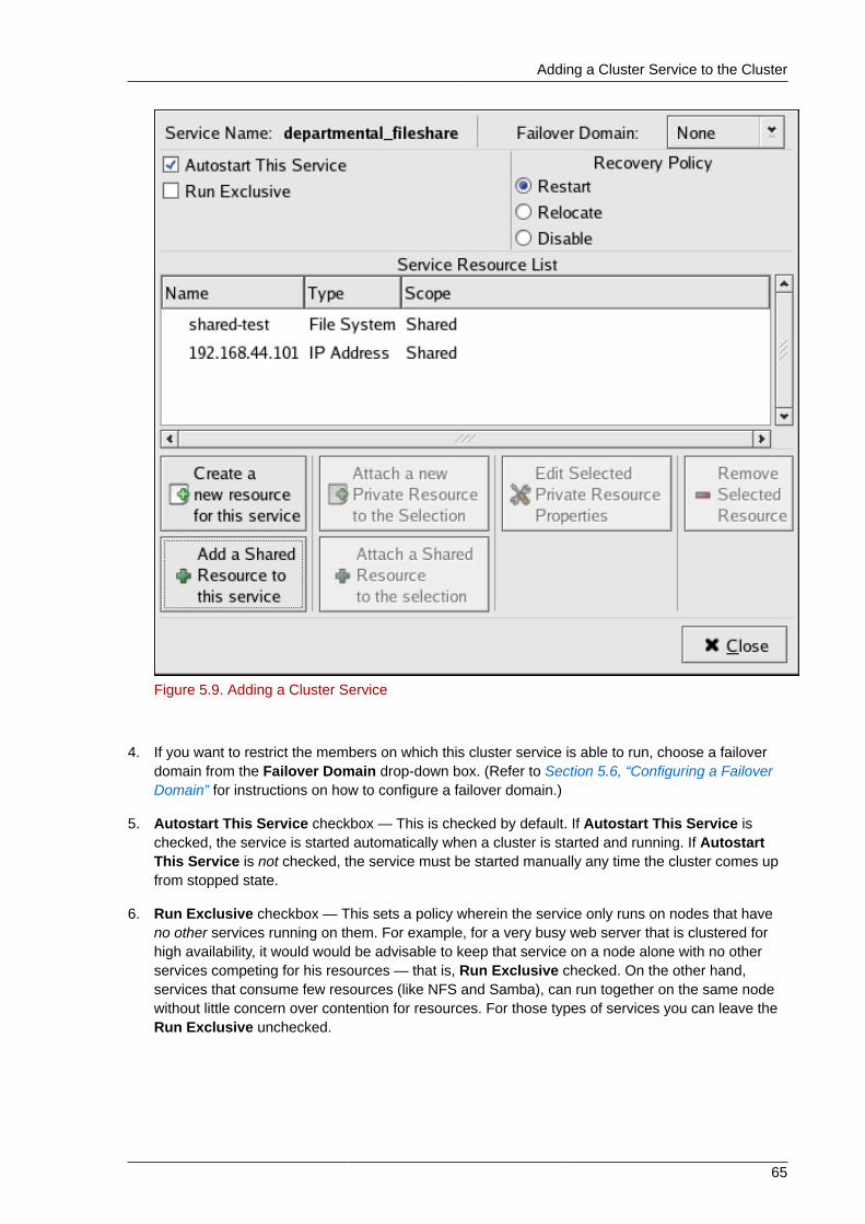
Adding a Cluster Service to the Cluster
65
Figure 5.9. Adding a Cluster Service
4. If you want to restrict the members on which this cluster service is able to run, choose a failoverdomain from the Failover Domain drop-down box. (Refer to Section 5.6, “Configuring a FailoverDomain” for instructions on how to configure a failover domain.)
5. Autostart This Service checkbox — This is checked by default. If Autostart This Service ischecked, the service is started automatically when a cluster is started and running. If AutostartThis Service is not checked, the service must be started manually any time the cluster comes upfrom stopped state.
6. Run Exclusive checkbox — This sets a policy wherein the service only runs on nodes that haveno other services running on them. For example, for a very busy web server that is clustered forhigh availability, it would would be advisable to keep that service on a node alone with no otherservices competing for his resources — that is, Run Exclusive checked. On the other hand,services that consume few resources (like NFS and Samba), can run together on the same nodewithout little concern over contention for resources. For those types of services you can leave theRun Exclusive unchecked.
Chapter 5. Configuring Red Hat Cluster With system-config-cluster
66
Note
Circumstances that require enabling Run Exclusive are rare. Enabling Run Exclusive canrender a service offline if the node it is running on fails and no other nodes are empty.
7. Select a recovery policy to specify how the resource manager should recover from a servicefailure. At the upper right of the Service Management dialog box, there are three RecoveryPolicy options available:
• Restart — Restart the service in the node the service is currently located. The default setting isRestart. If the service cannot be restarted in the current node, the service is relocated.
• Relocate — Relocate the service before restarting. Do not restart the node where the service iscurrently located.
• Disable — Do not restart the service at all.
8. Click the Add a Shared Resource to this service button and choose the a resource listed thatyou have configured in Section 5.7, “Adding Cluster Resources”.
Note
If you are adding a Samba-service resource, connect a Samba-service resource directly tothe service, not to a resource within a service. That is, at the Service Management dialogbox, use either Create a new resource for this service or Add a Shared Resource to thisservice; do not use Attach a new Private Resource to the Selection or Attach a SharedResource to the selection.
9. If needed, you may also create a private resource that you can create that becomes a subordinateresource by clicking on the Attach a new Private Resource to the Selection button. The processis the same as creating a shared resource described in Section 5.7, “Adding Cluster Resources”.The private resource will appear as a child to the shared resource to which you associated withthe shared resource. Click the triangle icon next to the shared resource to display any privateresources associated.
10. When finished, click OK.
11. Choose File => Save to save the changes to the cluster configuration.
Propagating The Configuration File: New Cluster
67
Note
To verify the existence of the IP service resource used in a cluster service, you must use the /sbin/ip addr list command on a cluster node. The following output shows the /sbin/ipaddr list command executed on a node running a cluster service:
1: lo: <LOOPBACK,UP> mtu 16436 qdisc noqueue link/loopback 00:00:00:00:00:00 brd 00:00:00:00:00:00 inet 127.0.0.1/8 scope host lo inet6 ::1/128 scope host valid_lft forever preferred_lft forever2: eth0: <BROADCAST,MULTICAST,UP> mtu 1356 qdisc pfifo_fast qlen 1000 link/ether 00:05:5d:9a:d8:91 brd ff:ff:ff:ff:ff:ff inet 10.11.4.31/22 brd 10.11.7.255 scope global eth0 inet6 fe80::205:5dff:fe9a:d891/64 scope link inet 10.11.4.240/22 scope global secondary eth0 valid_lft forever preferred_lft forever
5.9. Propagating The Configuration File: New ClusterFor newly defined clusters, you must propagate the configuration file to the cluster nodes as follows:
1. Log in to the node where you created the configuration file.
2. Using the scp command, copy the /etc/cluster/cluster.conf file to all nodes in thecluster.
Note
Propagating the cluster configuration file this way is necessary for the first time a cluster iscreated. Once a cluster is installed and running, the cluster configuration file is propagatedusing the Red Hat cluster management GUI Send to Cluster button. For more informationabout propagating the cluster configuration using the GUI Send to Cluster button, refer toSection 6.3, “Modifying the Cluster Configuration”.
5.10. Starting the Cluster SoftwareAfter you have propagated the cluster configuration to the cluster nodes you can either reboot eachnode or start the cluster software on each cluster node by running the following commands at eachnode in this order:
1. service cman start
2. service clvmd start, if CLVM has been used to create clustered volumes
Chapter 5. Configuring Red Hat Cluster With system-config-cluster
68
Note
Shared storage for use in Red Hat Cluster Suite requires that you be running the clusterlogical volume manager daemon (clvmd) or the High Availability Logical VolumeManagement agents (HA-LVM). If you are not able to use either the clvmd daemon or HA-LVM for operational reasons or because you do not have the correct entitlements, you mustnot use single-instance LVM on the shared disk as this may result in data corruption. If youhave any concerns please contact your Red Hat service representative.
3. service gfs start, if you are using Red Hat GFS
4. service rgmanager start
5. Start the Red Hat Cluster Suite management GUI. At the Cluster Configuration Tool tab, verifythat the configuration is correct. At the Cluster Status Tool tab verify that the nodes and servicesare running as expected.
Chapter 6.
69
Managing Red Hat Cluster Withsystem-config-clusterThis chapter describes various administrative tasks for managing a Red Hat Cluster and consists ofthe following sections:
• Section 6.1, “Starting and Stopping the Cluster Software”
• Section 6.2, “Managing High-Availability Services”
• Section 6.4, “Backing Up and Restoring the Cluster Database”
• Section 6.5, “Disabling the Cluster Software”
• Section 6.6, “Diagnosing and Correcting Problems in a Cluster”
Note
While system-config-cluster provides several convenient tools for configuring andmanaging a Red Hat Cluster, the newer, more comprehensive tool, Conga, provides moreconvenience and flexibility than system-config-cluster. You may want to consider usingConga instead (refer to Chapter 3, Configuring Red Hat Cluster With Conga and Chapter 4,Managing Red Hat Cluster With Conga).
6.1. Starting and Stopping the Cluster SoftwareTo start the cluster software on a member, type the following commands in this order:
1. service cman start
2. service clvmd start, if CLVM has been used to create clustered volumes
3. service gfs start, if you are using Red Hat GFS
4. service rgmanager start
To stop the cluster software on a member, type the following commands in this order:
1. service rgmanager stop
2. service gfs stop, if you are using Red Hat GFS
3. service clvmd stop, if CLVM has been used to create clustered volumes
4. service cman stop
Stopping the cluster services on a member causes its services to fail over to an active member.
6.2. Managing High-Availability ServicesYou can manage cluster services with the Cluster Status Tool (Figure 6.1, “Cluster Status Tool”)through the Cluster Management tab in Cluster Administration GUI.
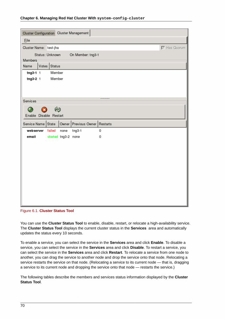
Chapter 6. Managing Red Hat Cluster With system-config-cluster
70
Figure 6.1. Cluster Status Tool
You can use the Cluster Status Tool to enable, disable, restart, or relocate a high-availability service.The Cluster Status Tool displays the current cluster status in the Services area and automaticallyupdates the status every 10 seconds.
To enable a service, you can select the service in the Services area and click Enable. To disable aservice, you can select the service in the Services area and click Disable. To restart a service, youcan select the service in the Services area and click Restart. To relocate a service from one node toanother, you can drag the service to another node and drop the service onto that node. Relocating aservice restarts the service on that node. (Relocating a service to its current node — that is, dragginga service to its current node and dropping the service onto that node — restarts the service.)
The following tables describe the members and services status information displayed by the ClusterStatus Tool.
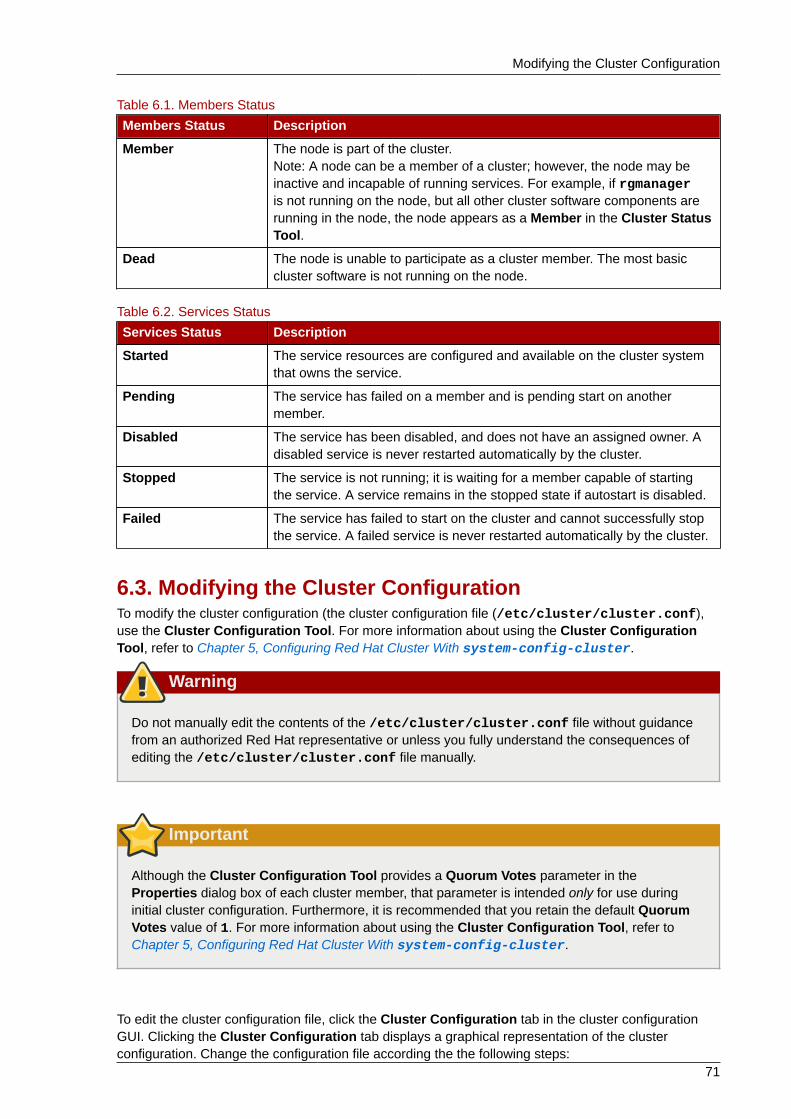
Modifying the Cluster Configuration
71
Table 6.1. Members Status
Members Status Description
Member The node is part of the cluster.Note: A node can be a member of a cluster; however, the node may beinactive and incapable of running services. For example, if rgmanageris not running on the node, but all other cluster software components arerunning in the node, the node appears as a Member in the Cluster StatusTool.
Dead The node is unable to participate as a cluster member. The most basiccluster software is not running on the node.
Table 6.2. Services Status
Services Status Description
Started The service resources are configured and available on the cluster systemthat owns the service.
Pending The service has failed on a member and is pending start on anothermember.
Disabled The service has been disabled, and does not have an assigned owner. Adisabled service is never restarted automatically by the cluster.
Stopped The service is not running; it is waiting for a member capable of startingthe service. A service remains in the stopped state if autostart is disabled.
Failed The service has failed to start on the cluster and cannot successfully stopthe service. A failed service is never restarted automatically by the cluster.
6.3. Modifying the Cluster ConfigurationTo modify the cluster configuration (the cluster configuration file (/etc/cluster/cluster.conf),use the Cluster Configuration Tool. For more information about using the Cluster ConfigurationTool, refer to Chapter 5, Configuring Red Hat Cluster With system-config-cluster.
Warning
Do not manually edit the contents of the /etc/cluster/cluster.conf file without guidancefrom an authorized Red Hat representative or unless you fully understand the consequences ofediting the /etc/cluster/cluster.conf file manually.
Important
Although the Cluster Configuration Tool provides a Quorum Votes parameter in theProperties dialog box of each cluster member, that parameter is intended only for use duringinitial cluster configuration. Furthermore, it is recommended that you retain the default QuorumVotes value of 1. For more information about using the Cluster Configuration Tool, refer toChapter 5, Configuring Red Hat Cluster With system-config-cluster.
To edit the cluster configuration file, click the Cluster Configuration tab in the cluster configurationGUI. Clicking the Cluster Configuration tab displays a graphical representation of the clusterconfiguration. Change the configuration file according the the following steps:
Chapter 6. Managing Red Hat Cluster With system-config-cluster
72
1. Make changes to cluster elements (for example, create a service).
2. Propagate the updated configuration file throughout the cluster by clicking Send to Cluster.
Note
The Cluster Configuration Tool does not display the Send to Cluster button if the clusteris new and has not been started yet, or if the node from which you are running the ClusterConfiguration Tool is not a member of the cluster. If the Send to Cluster button is notdisplayed, you can still use the Cluster Configuration Tool; however, you cannot propagatethe configuration. You can still save the configuration file. For information about using theCluster Configuration Tool for a new cluster configuration, refer to Chapter 5, ConfiguringRed Hat Cluster With system-config-cluster.
3. Clicking Send to Cluster causes a Warning dialog box to be displayed. Click Yes to save andpropagate the configuration.
4. Clicking Yes causes an Information dialog box to be displayed, confirming that the currentconfiguration has been propagated to the cluster. Click OK.
5. Click the Cluster Management tab and verify that the changes have been propagated to thecluster members.
6.4. Backing Up and Restoring the Cluster DatabaseThe Cluster Configuration Tool automatically retains backup copies of the three most recently usedconfiguration files (besides the currently used configuration file). Retaining the backup copies is usefulif the cluster does not function correctly because of misconfiguration and you need to return to aprevious working configuration.
Each time you save a configuration file, the Cluster Configuration Tool saves backup copies ofthe three most recently used configuration files as /etc/cluster/cluster.conf.bak.1, /etc/cluster/cluster.conf.bak.2, and /etc/cluster/cluster.conf.bak.3. Thebackup file /etc/cluster/cluster.conf.bak.1 is the newest backup, /etc/cluster/cluster.conf.bak.2 is the second newest backup, and /etc/cluster/cluster.conf.bak.3is the third newest backup.
If a cluster member becomes inoperable because of misconfiguration, restore the configuration fileaccording to the following steps:
1. At the Cluster Configuration Tool tab of the Red Hat Cluster Suite management GUI, click File=> Open.
2. Clicking File => Open causes the system-config-cluster dialog box to be displayed.
3. At the the system-config-cluster dialog box, select a backup file (for example, /etc/cluster/cluster.conf.bak.1). Verify the file selection in the Selection box and click OK.
4. Increment the configuration version beyond the current working version number as follows:
a. Click Cluster => Edit Cluster Properties.
b. At the Cluster Properties dialog box, change the Config Version value and click OK.
Disabling the Cluster Software
73
5. Click File => Save As.
6. Clicking File => Save As causes the system-config-cluster dialog box to be displayed.
7. At the the system-config-cluster dialog box, select /etc/cluster/cluster.conf and clickOK. (Verify the file selection in the Selection box.)
8. Clicking OK causes an Information dialog box to be displayed. At that dialog box, click OK.
9. Propagate the updated configuration file throughout the cluster by clicking Send to Cluster.
Note
The Cluster Configuration Tool does not display the Send to Cluster button if the clusteris new and has not been started yet, or if the node from which you are running the ClusterConfiguration Tool is not a member of the cluster. If the Send to Cluster button is notdisplayed, you can still use the Cluster Configuration Tool; however, you cannot propagatethe configuration. You can still save the configuration file. For information about using theCluster Configuration Tool for a new cluster configuration, refer to Chapter 5, ConfiguringRed Hat Cluster With system-config-cluster.
10. Clicking Send to Cluster causes a Warning dialog box to be displayed. Click Yes to propagatethe configuration.
11. Click the Cluster Management tab and verify that the changes have been propagated to thecluster members.
6.5. Disabling the Cluster SoftwareIt may become necessary to temporarily disable the cluster software on a cluster member. Forexample, if a cluster member experiences a hardware failure, you may want to reboot that member,but prevent it from rejoining the cluster to perform maintenance on the system.
Use the /sbin/chkconfig command to stop the member from joining the cluster at boot-up asfollows:
# chkconfig --level 2345 rgmanager off# chkconfig --level 2345 gfs off# chkconfig --level 2345 clvmd off# chkconfig --level 2345 cman off
Once the problems with the disabled cluster member have been resolved, use the followingcommands to allow the member to rejoin the cluster:
# chkconfig --level 2345 rgmanager on# chkconfig --level 2345 gfs on# chkconfig --level 2345 clvmd on# chkconfig --level 2345 cman on
You can then reboot the member for the changes to take effect or run the following commands in theorder shown to restart cluster software:
Chapter 6. Managing Red Hat Cluster With system-config-cluster
74
1. service cman start
2. service clvmd start, if CLVM has been used to create clustered volumes
3. service gfs start, if you are using Red Hat GFS
4. service rgmanager start
6.6. Diagnosing and Correcting Problems in a ClusterFor information about diagnosing and correcting problems in a cluster, contact an authorized Red Hatsupport representative.
75
Appendix A. Example of Setting UpApache HTTP ServerThis appendix provides an example of setting up a highly available Apache HTTP Server on a Red HatCluster. The example describes how to set up a service to fail over an Apache HTTP Server. Variablesin the example apply to this example only; they are provided to assist setting up a service that suitsyour requirements.
Note
This example uses the Cluster Configuration Tool (system-config-cluster). You can usecomparable Conga functions to make an Apache HTTP Server highly available on a Red HatCluster.
A.1. Apache HTTP Server Setup OverviewFirst, configure Apache HTTP Server on all nodes in the cluster. If using a failover domain , assignthe service to all cluster nodes configured to run the Apache HTTP Server. Refer to Section 5.6,“Configuring a Failover Domain” for instructions. The cluster software ensures that only one clustersystem runs the Apache HTTP Server at one time. The example configuration consists of installing thehttpd RPM package on all cluster nodes (or on nodes in the failover domain, if used) and configuringa shared GFS shared resource for the Web content.
When installing the Apache HTTP Server on the cluster systems, run the following command toensure that the cluster nodes do not automatically start the service when the system boots:
# chkconfig --del httpd
Rather than having the system init scripts spawn the httpd daemon, the cluster infrastructureinitializes the service on the active cluster node. This ensures that the corresponding IP address andfile system mounts are active on only one cluster node at a time.
When adding an httpd service, a floating IP address must be assigned to the service so that the IPaddress will transfer from one cluster node to another in the event of failover or service relocation.The cluster infrastructure binds this IP address to the network interface on the cluster system that iscurrently running the Apache HTTP Server. This IP address ensures that the cluster node runninghttpd is transparent to the clients accessing the service.
The file systems that contain the Web content cannot be automatically mounted on the shared storageresource when the cluster nodes boot. Instead, the cluster software must mount and unmount thefile system as the httpd service is started and stopped. This prevents the cluster systems fromaccessing the same data simultaneously, which may result in data corruption. Therefore, do notinclude the file systems in the /etc/fstab file.
A.2. Configuring Shared StorageTo set up the shared file system resource, perform the following tasks as root on one cluster system:
1. On one cluster node, use the interactive parted utility to create a partition to use for thedocument root directory. Note that it is possible to create multiple document root directories ondifferent disk partitions.
Appendix A. Example of Setting Up Apache HTTP Server
76
2. Use the mkfs command to create an ext3 file system on the partition you created in the previousstep. Specify the drive letter and the partition number. For example:
# mkfs -t ext3 /dev/sde3
3. Mount the file system that contains the document root directory. For example:
# mount /dev/sde3 /var/www/html
Do not add this mount information to the /etc/fstab file because only the cluster software canmount and unmount file systems used in a service.
4. Copy all the required files to the document root directory.
5. If you have CGI files or other files that must be in different directories or in separate partitions,repeat these steps, as needed.
A.3. Installing and Configuring the Apache HTTP ServerThe Apache HTTP Server must be installed and configured on all nodes in the assigned failoverdomain, if used, or in the cluster. The basic server configuration must be the same on all nodes onwhich it runs for the service to fail over correctly. The following example shows a basic Apache HTTPServer installation that includes no third-party modules or performance tuning.
On all node in the cluster (or nodes in the failover domain, if used), install the httpd RPM package.For example:
rpm -Uvh httpd-<version>.<arch>.rpm
To configure the Apache HTTP Server as a cluster service, perform the following tasks:
1. Edit the /etc/httpd/conf/httpd.conf configuration file and customize the file according toyour configuration. For example:
• Specify the directory that contains the HTML files. Also specify this mount point when adding theservice to the cluster configuration. It is only required to change this field if the mount point forthe web site's content differs from the default setting of /var/www/html/. For example:
DocumentRoot "/mnt/httpdservice/html"
• Specify a unique IP address to which the service will listen for requests. For example:
Listen 192.168.1.100:80
This IP address then must be configured as a cluster resource for the service using the ClusterConfiguration Tool.
• If the script directory resides in a non-standard location, specify the directory that contains theCGI programs. For example:
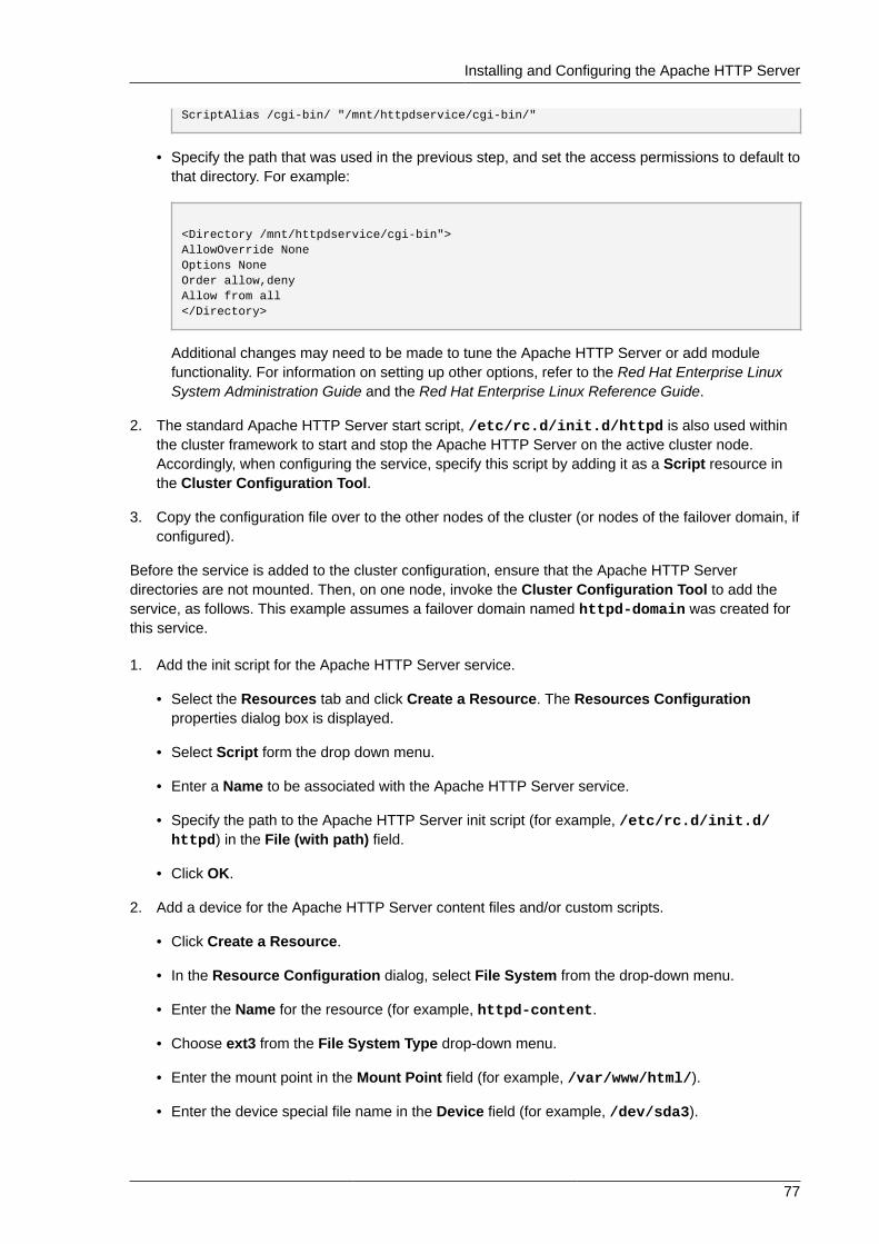
Installing and Configuring the Apache HTTP Server
77
ScriptAlias /cgi-bin/ "/mnt/httpdservice/cgi-bin/"
• Specify the path that was used in the previous step, and set the access permissions to default tothat directory. For example:
<Directory /mnt/httpdservice/cgi-bin">AllowOverride NoneOptions None Order allow,deny Allow from all </Directory>
Additional changes may need to be made to tune the Apache HTTP Server or add modulefunctionality. For information on setting up other options, refer to the Red Hat Enterprise LinuxSystem Administration Guide and the Red Hat Enterprise Linux Reference Guide.
2. The standard Apache HTTP Server start script, /etc/rc.d/init.d/httpd is also used withinthe cluster framework to start and stop the Apache HTTP Server on the active cluster node.Accordingly, when configuring the service, specify this script by adding it as a Script resource inthe Cluster Configuration Tool.
3. Copy the configuration file over to the other nodes of the cluster (or nodes of the failover domain, ifconfigured).
Before the service is added to the cluster configuration, ensure that the Apache HTTP Serverdirectories are not mounted. Then, on one node, invoke the Cluster Configuration Tool to add theservice, as follows. This example assumes a failover domain named httpd-domain was created forthis service.
1. Add the init script for the Apache HTTP Server service.
• Select the Resources tab and click Create a Resource. The Resources Configurationproperties dialog box is displayed.
• Select Script form the drop down menu.
• Enter a Name to be associated with the Apache HTTP Server service.
• Specify the path to the Apache HTTP Server init script (for example, /etc/rc.d/init.d/httpd) in the File (with path) field.
• Click OK.
2. Add a device for the Apache HTTP Server content files and/or custom scripts.
• Click Create a Resource.
• In the Resource Configuration dialog, select File System from the drop-down menu.
• Enter the Name for the resource (for example, httpd-content.
• Choose ext3 from the File System Type drop-down menu.
• Enter the mount point in the Mount Point field (for example, /var/www/html/).
• Enter the device special file name in the Device field (for example, /dev/sda3).
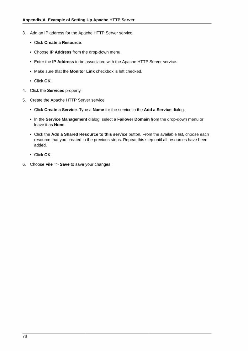
Appendix A. Example of Setting Up Apache HTTP Server
78
3. Add an IP address for the Apache HTTP Server service.
• Click Create a Resource.
• Choose IP Address from the drop-down menu.
• Enter the IP Address to be associated with the Apache HTTP Server service.
• Make sure that the Monitor Link checkbox is left checked.
• Click OK.
4. Click the Services property.
5. Create the Apache HTTP Server service.
• Click Create a Service. Type a Name for the service in the Add a Service dialog.
• In the Service Management dialog, select a Failover Domain from the drop-down menu orleave it as None.
• Click the Add a Shared Resource to this service button. From the available list, choose eachresource that you created in the previous steps. Repeat this step until all resources have beenadded.
• Click OK.
6. Choose File => Save to save your changes.
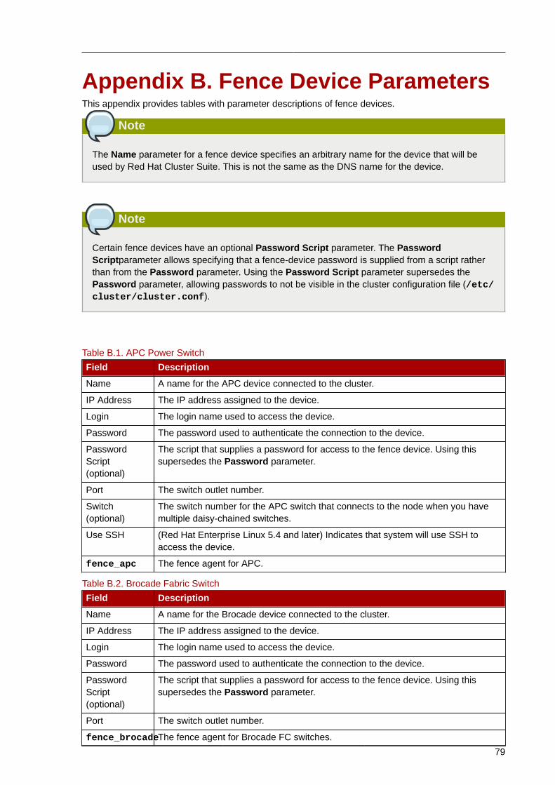
79
Appendix B. Fence Device ParametersThis appendix provides tables with parameter descriptions of fence devices.
Note
The Name parameter for a fence device specifies an arbitrary name for the device that will beused by Red Hat Cluster Suite. This is not the same as the DNS name for the device.
Note
Certain fence devices have an optional Password Script parameter. The PasswordScriptparameter allows specifying that a fence-device password is supplied from a script ratherthan from the Password parameter. Using the Password Script parameter supersedes thePassword parameter, allowing passwords to not be visible in the cluster configuration file (/etc/cluster/cluster.conf).
Table B.1. APC Power Switch
Field Description
Name A name for the APC device connected to the cluster.
IP Address The IP address assigned to the device.
Login The login name used to access the device.
Password The password used to authenticate the connection to the device.
PasswordScript(optional)
The script that supplies a password for access to the fence device. Using thissupersedes the Password parameter.
Port The switch outlet number.
Switch(optional)
The switch number for the APC switch that connects to the node when you havemultiple daisy-chained switches.
Use SSH (Red Hat Enterprise Linux 5.4 and later) Indicates that system will use SSH toaccess the device.
fence_apc The fence agent for APC.
Table B.2. Brocade Fabric Switch
Field Description
Name A name for the Brocade device connected to the cluster.
IP Address The IP address assigned to the device.
Login The login name used to access the device.
Password The password used to authenticate the connection to the device.
PasswordScript(optional)
The script that supplies a password for access to the fence device. Using thissupersedes the Password parameter.
Port The switch outlet number.
fence_brocadeThe fence agent for Brocade FC switches.
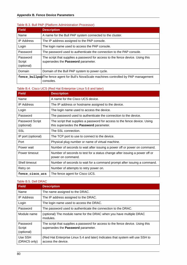
Appendix B. Fence Device Parameters
80
Table B.3. Bull PAP (Platform Administration Processor)
Field Description
Name A name for the Bull PAP system connected to the cluster.
IP Address The IP address assigned to the PAP console.
Login The login name used to access the PAP console.
Password The password used to authenticate the connection to the PAP console.
PasswordScript(optional)
The script that supplies a password for access to the fence device. Using thissupersedes the Password parameter.
Domain Domain of the Bull PAP system to power cycle.
fence_bullpapThe fence agent for Bull’s NovaScale machines controlled by PAP managementconsoles.
Table B.4. Cisco UCS (Red Hat Enterprise Linux 5.6 and later)
Field Description
Name A name for the Cisco UCS device.
IP Address The IP address or hostname assigned to the device.
Login The login name used to access the device.
Password The password used to authenticate the connection to the device.
Password Script(optional)
The script that supplies a password for access to the fence device. Usingthis supersedes the Password parameter.
SSL The SSL connection.
IP port (optional) The TCP port to use to connect to the device.
Port Physical plug number or name of virtual machine.
Power wait Number of seconds to wait after issuing a power off or power on command.
Power timeout Number of seconds to test for a status change after issuing a power off orpower on command.
Shell timeout Number of seconds to wait for a command prompt after issuing a command.
Retry on Number of attempts to retry power on.
fence_cisco_ucs The fence agent for Cisco UCS.
Table B.5. Dell DRAC
Field Description
Name The name assigned to the DRAC.
IP Address The IP address assigned to the DRAC.
Login The login name used to access the DRAC.
Password The password used to authenticate the connection to the DRAC.
Module name (optional) The module name for the DRAC when you have multiple DRACmodules.
PasswordScript(optional)
The script that supplies a password for access to the fence device. Using thissupersedes the Password parameter.
Use SSH(DRAC5 only)
(Red Hat Enterprise Linux 5.4 and later) Indicates that system will use SSH toaccess the device.
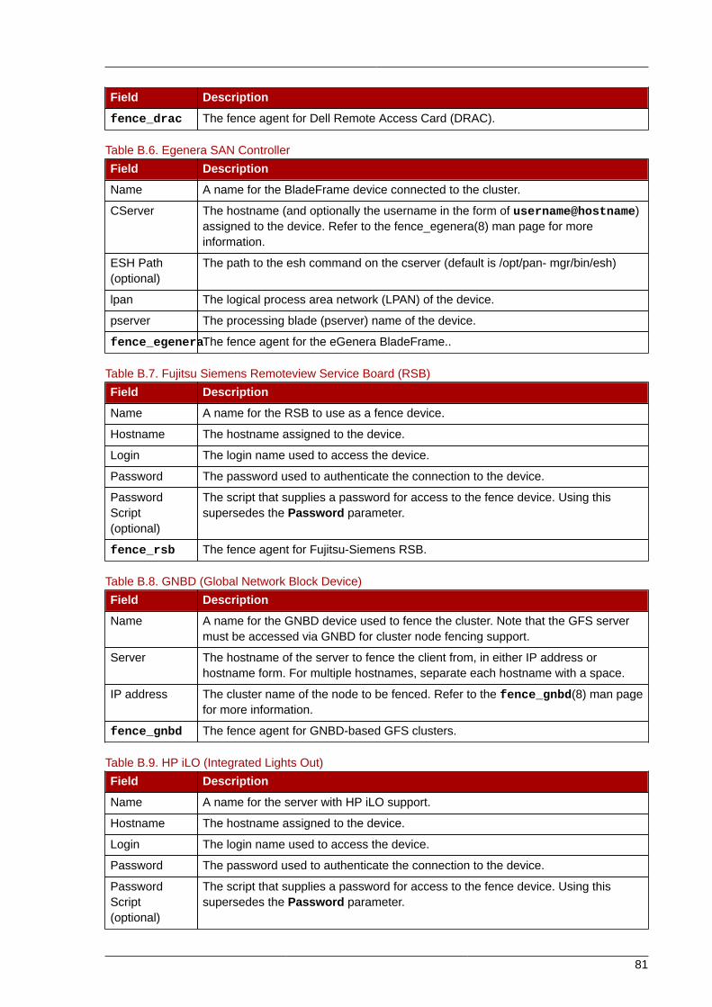
81
Field Description
fence_drac The fence agent for Dell Remote Access Card (DRAC).
Table B.6. Egenera SAN Controller
Field Description
Name A name for the BladeFrame device connected to the cluster.
CServer The hostname (and optionally the username in the form of username@hostname)assigned to the device. Refer to the fence_egenera(8) man page for moreinformation.
ESH Path(optional)
The path to the esh command on the cserver (default is /opt/pan- mgr/bin/esh)
lpan The logical process area network (LPAN) of the device.
pserver The processing blade (pserver) name of the device.
fence_egeneraThe fence agent for the eGenera BladeFrame..
Table B.7. Fujitsu Siemens Remoteview Service Board (RSB)
Field Description
Name A name for the RSB to use as a fence device.
Hostname The hostname assigned to the device.
Login The login name used to access the device.
Password The password used to authenticate the connection to the device.
PasswordScript(optional)
The script that supplies a password for access to the fence device. Using thissupersedes the Password parameter.
fence_rsb The fence agent for Fujitsu-Siemens RSB.
Table B.8. GNBD (Global Network Block Device)
Field Description
Name A name for the GNBD device used to fence the cluster. Note that the GFS servermust be accessed via GNBD for cluster node fencing support.
Server The hostname of the server to fence the client from, in either IP address orhostname form. For multiple hostnames, separate each hostname with a space.
IP address The cluster name of the node to be fenced. Refer to the fence_gnbd(8) man pagefor more information.
fence_gnbd The fence agent for GNBD-based GFS clusters.
Table B.9. HP iLO (Integrated Lights Out)
Field Description
Name A name for the server with HP iLO support.
Hostname The hostname assigned to the device.
Login The login name used to access the device.
Password The password used to authenticate the connection to the device.
PasswordScript(optional)
The script that supplies a password for access to the fence device. Using thissupersedes the Password parameter.
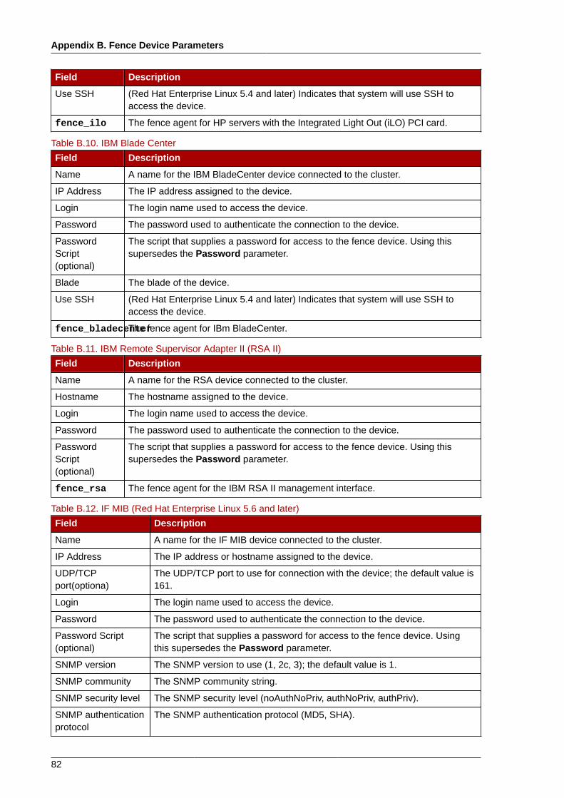
Appendix B. Fence Device Parameters
82
Field Description
Use SSH (Red Hat Enterprise Linux 5.4 and later) Indicates that system will use SSH toaccess the device.
fence_ilo The fence agent for HP servers with the Integrated Light Out (iLO) PCI card.
Table B.10. IBM Blade Center
Field Description
Name A name for the IBM BladeCenter device connected to the cluster.
IP Address The IP address assigned to the device.
Login The login name used to access the device.
Password The password used to authenticate the connection to the device.
PasswordScript(optional)
The script that supplies a password for access to the fence device. Using thissupersedes the Password parameter.
Blade The blade of the device.
Use SSH (Red Hat Enterprise Linux 5.4 and later) Indicates that system will use SSH toaccess the device.
fence_bladecenterThe fence agent for IBm BladeCenter.
Table B.11. IBM Remote Supervisor Adapter II (RSA II)
Field Description
Name A name for the RSA device connected to the cluster.
Hostname The hostname assigned to the device.
Login The login name used to access the device.
Password The password used to authenticate the connection to the device.
PasswordScript(optional)
The script that supplies a password for access to the fence device. Using thissupersedes the Password parameter.
fence_rsa The fence agent for the IBM RSA II management interface.
Table B.12. IF MIB (Red Hat Enterprise Linux 5.6 and later)
Field Description
Name A name for the IF MIB device connected to the cluster.
IP Address The IP address or hostname assigned to the device.
UDP/TCPport(optiona)
The UDP/TCP port to use for connection with the device; the default value is161.
Login The login name used to access the device.
Password The password used to authenticate the connection to the device.
Password Script(optional)
The script that supplies a password for access to the fence device. Usingthis supersedes the Password parameter.
SNMP version The SNMP version to use (1, 2c, 3); the default value is 1.
SNMP community The SNMP community string.
SNMP security level The SNMP security level (noAuthNoPriv, authNoPriv, authPriv).
SNMP authenticationprotocol
The SNMP authentication protocol (MD5, SHA).
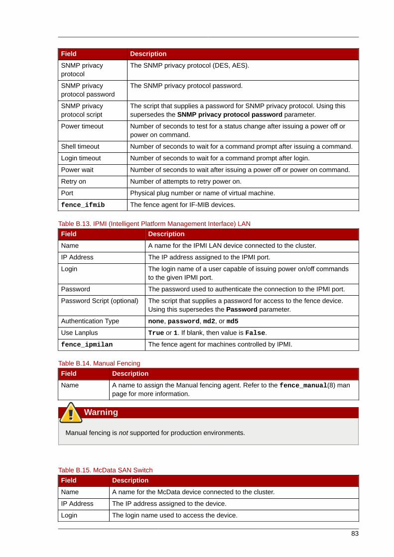
83
Field Description
SNMP privacyprotocol
The SNMP privacy protocol (DES, AES).
SNMP privacyprotocol password
The SNMP privacy protocol password.
SNMP privacyprotocol script
The script that supplies a password for SNMP privacy protocol. Using thissupersedes the SNMP privacy protocol password parameter.
Power timeout Number of seconds to test for a status change after issuing a power off orpower on command.
Shell timeout Number of seconds to wait for a command prompt after issuing a command.
Login timeout Number of seconds to wait for a command prompt after login.
Power wait Number of seconds to wait after issuing a power off or power on command.
Retry on Number of attempts to retry power on.
Port Physical plug number or name of virtual machine.
fence_ifmib The fence agent for IF-MIB devices.
Table B.13. IPMI (Intelligent Platform Management Interface) LAN
Field Description
Name A name for the IPMI LAN device connected to the cluster.
IP Address The IP address assigned to the IPMI port.
Login The login name of a user capable of issuing power on/off commandsto the given IPMI port.
Password The password used to authenticate the connection to the IPMI port.
Password Script (optional) The script that supplies a password for access to the fence device.Using this supersedes the Password parameter.
Authentication Type none, password, md2, or md5
Use Lanplus True or 1. If blank, then value is False.
fence_ipmilan The fence agent for machines controlled by IPMI.
Table B.14. Manual Fencing
Field Description
Name A name to assign the Manual fencing agent. Refer to the fence_manual(8) manpage for more information.
Warning
Manual fencing is not supported for production environments.
Table B.15. McData SAN Switch
Field Description
Name A name for the McData device connected to the cluster.
IP Address The IP address assigned to the device.
Login The login name used to access the device.
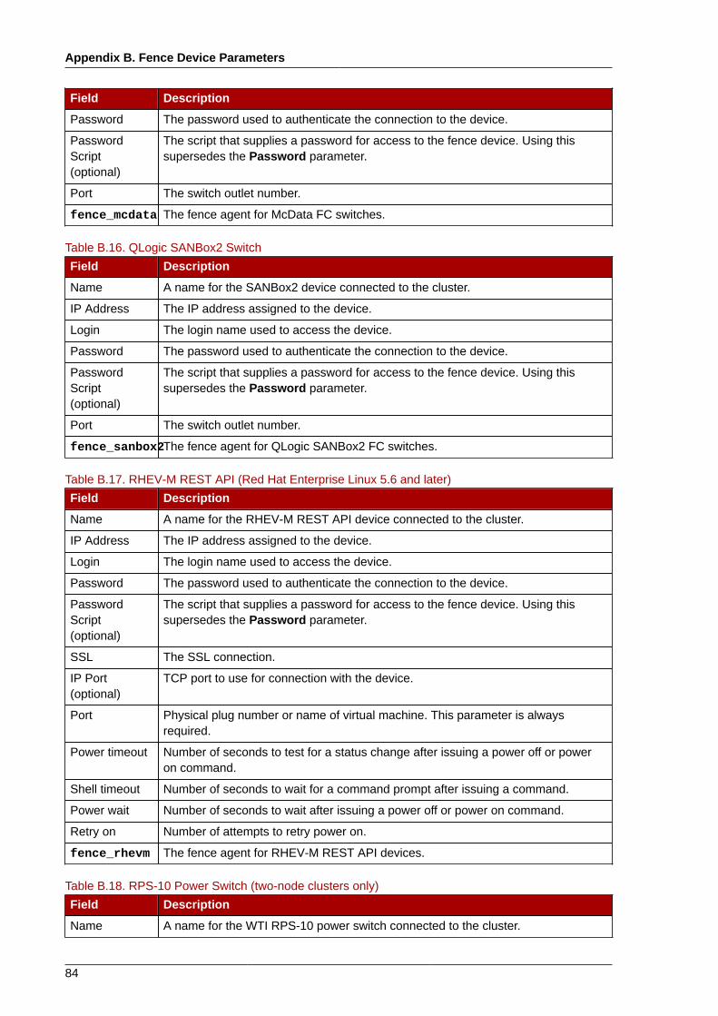
Appendix B. Fence Device Parameters
84
Field Description
Password The password used to authenticate the connection to the device.
PasswordScript(optional)
The script that supplies a password for access to the fence device. Using thissupersedes the Password parameter.
Port The switch outlet number.
fence_mcdata The fence agent for McData FC switches.
Table B.16. QLogic SANBox2 Switch
Field Description
Name A name for the SANBox2 device connected to the cluster.
IP Address The IP address assigned to the device.
Login The login name used to access the device.
Password The password used to authenticate the connection to the device.
PasswordScript(optional)
The script that supplies a password for access to the fence device. Using thissupersedes the Password parameter.
Port The switch outlet number.
fence_sanbox2The fence agent for QLogic SANBox2 FC switches.
Table B.17. RHEV-M REST API (Red Hat Enterprise Linux 5.6 and later)
Field Description
Name A name for the RHEV-M REST API device connected to the cluster.
IP Address The IP address assigned to the device.
Login The login name used to access the device.
Password The password used to authenticate the connection to the device.
PasswordScript(optional)
The script that supplies a password for access to the fence device. Using thissupersedes the Password parameter.
SSL The SSL connection.
IP Port(optional)
TCP port to use for connection with the device.
Port Physical plug number or name of virtual machine. This parameter is alwaysrequired.
Power timeout Number of seconds to test for a status change after issuing a power off or poweron command.
Shell timeout Number of seconds to wait for a command prompt after issuing a command.
Power wait Number of seconds to wait after issuing a power off or power on command.
Retry on Number of attempts to retry power on.
fence_rhevm The fence agent for RHEV-M REST API devices.
Table B.18. RPS-10 Power Switch (two-node clusters only)
Field Description
Name A name for the WTI RPS-10 power switch connected to the cluster.
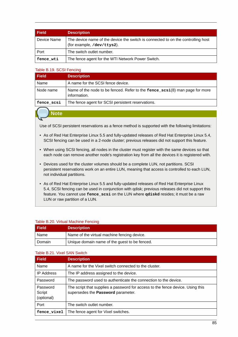
85
Field Description
Device Name The device name of the device the switch is connected to on the controlling host(for example, /dev/ttys2).
Port The switch outlet number.
fence_wti The fence agent for the WTI Network Power Switch.
Table B.19. SCSI Fencing
Field Description
Name A name for the SCSI fence device.
Node name Name of the node to be fenced. Refer to the fence_scsi(8) man page for moreinformation.
fence_scsi The fence agent for SCSI persistent reservations.
Note
Use of SCSI persistent reservations as a fence method is supported with the following limitations:
• As of Red Hat Enterprise Linux 5.5 and fully-updated releases of Red Hat Enterprise Linux 5.4,SCSI fencing can be used in a 2-node cluster; previous releases did not support this feature.
• When using SCSI fencing, all nodes in the cluster must register with the same devices so thateach node can remove another node's registration key from all the devices it is registered with.
• Devices used for the cluster volumes should be a complete LUN, not partitions. SCSIpersistent reservations work on an entire LUN, meaning that access is controlled to each LUN,not individual partitions.
• As of Red Hat Enterprise Linux 5.5 and fully-updated releases of Red Hat Enterprise Linux5.4, SCSI fencing can be used in conjunction with qdisk; previous releases did not support thisfeature. You cannot use fence_scsi on the LUN where qdiskd resides; it must be a rawLUN or raw partition of a LUN.
Table B.20. Virtual Machine Fencing
Field Description
Name Name of the virtual machine fencing device.
Domain Unique domain name of the guest to be fenced.
Table B.21. Vixel SAN Switch
Field Description
Name A name for the Vixel switch connected to the cluster.
IP Address The IP address assigned to the device.
Password The password used to authenticate the connection to the device.
PasswordScript(optional)
The script that supplies a password for access to the fence device. Using thissupersedes the Password parameter.
Port The switch outlet number.
fence_vixel The fence agent for Vixel switches.
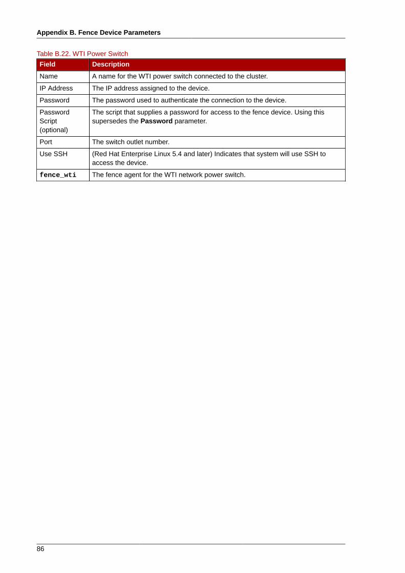
Appendix B. Fence Device Parameters
86
Table B.22. WTI Power Switch
Field Description
Name A name for the WTI power switch connected to the cluster.
IP Address The IP address assigned to the device.
Password The password used to authenticate the connection to the device.
PasswordScript(optional)
The script that supplies a password for access to the fence device. Using thissupersedes the Password parameter.
Port The switch outlet number.
Use SSH (Red Hat Enterprise Linux 5.4 and later) Indicates that system will use SSH toaccess the device.
fence_wti The fence agent for the WTI network power switch.
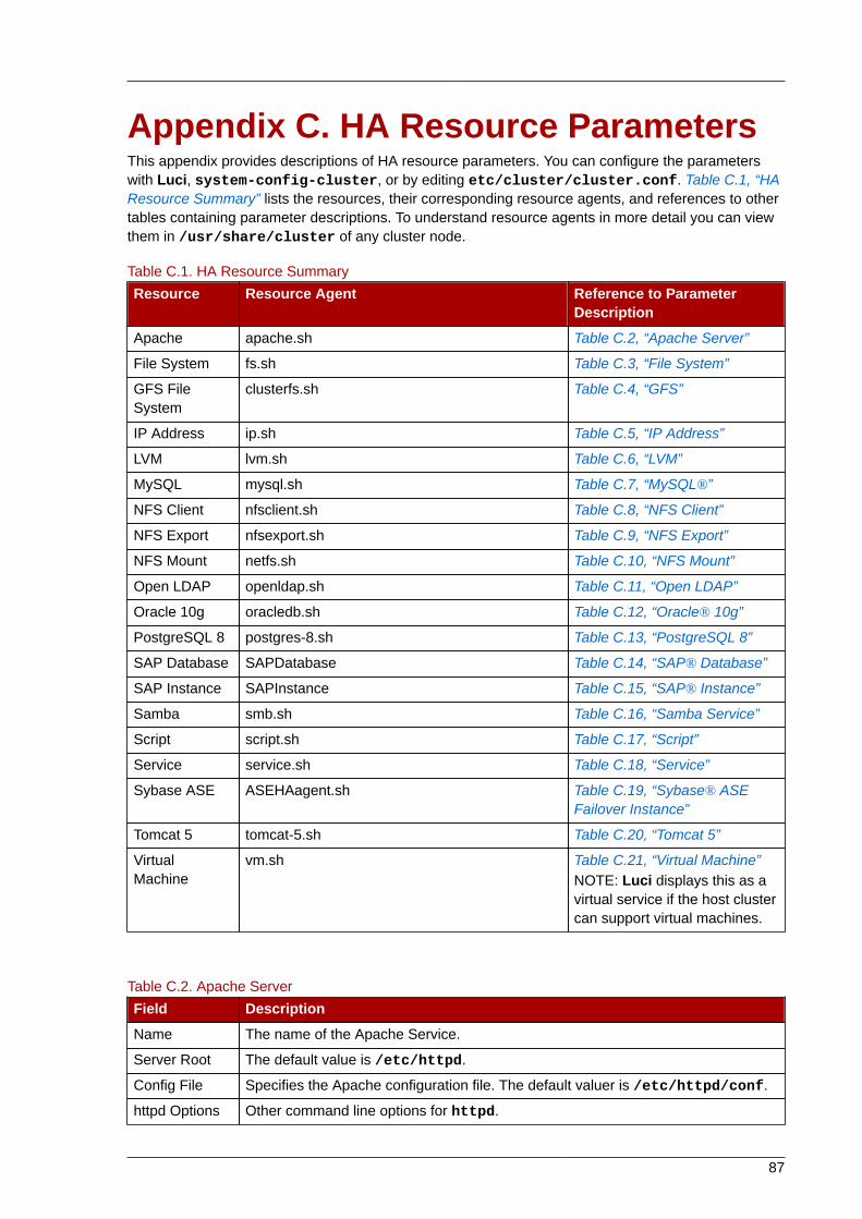
87
Appendix C. HA Resource ParametersThis appendix provides descriptions of HA resource parameters. You can configure the parameterswith Luci, system-config-cluster, or by editing etc/cluster/cluster.conf. Table C.1, “HAResource Summary” lists the resources, their corresponding resource agents, and references to othertables containing parameter descriptions. To understand resource agents in more detail you can viewthem in /usr/share/cluster of any cluster node.
Table C.1. HA Resource Summary
Resource Resource Agent Reference to ParameterDescription
Apache apache.sh Table C.2, “Apache Server”
File System fs.sh Table C.3, “File System”
GFS FileSystem
clusterfs.sh Table C.4, “GFS”
IP Address ip.sh Table C.5, “IP Address”
LVM lvm.sh Table C.6, “LVM”
MySQL mysql.sh Table C.7, “MySQL®”
NFS Client nfsclient.sh Table C.8, “NFS Client”
NFS Export nfsexport.sh Table C.9, “NFS Export”
NFS Mount netfs.sh Table C.10, “NFS Mount”
Open LDAP openldap.sh Table C.11, “Open LDAP”
Oracle 10g oracledb.sh Table C.12, “Oracle® 10g”
PostgreSQL 8 postgres-8.sh Table C.13, “PostgreSQL 8”
SAP Database SAPDatabase Table C.14, “SAP® Database”
SAP Instance SAPInstance Table C.15, “SAP® Instance”
Samba smb.sh Table C.16, “Samba Service”
Script script.sh Table C.17, “Script”
Service service.sh Table C.18, “Service”
Sybase ASE ASEHAagent.sh Table C.19, “Sybase® ASEFailover Instance”
Tomcat 5 tomcat-5.sh Table C.20, “Tomcat 5”
VirtualMachine
vm.sh Table C.21, “Virtual Machine”NOTE: Luci displays this as avirtual service if the host clustercan support virtual machines.
Table C.2. Apache Server
Field Description
Name The name of the Apache Service.
Server Root The default value is /etc/httpd.
Config File Specifies the Apache configuration file. The default valuer is /etc/httpd/conf.
httpd Options Other command line options for httpd.
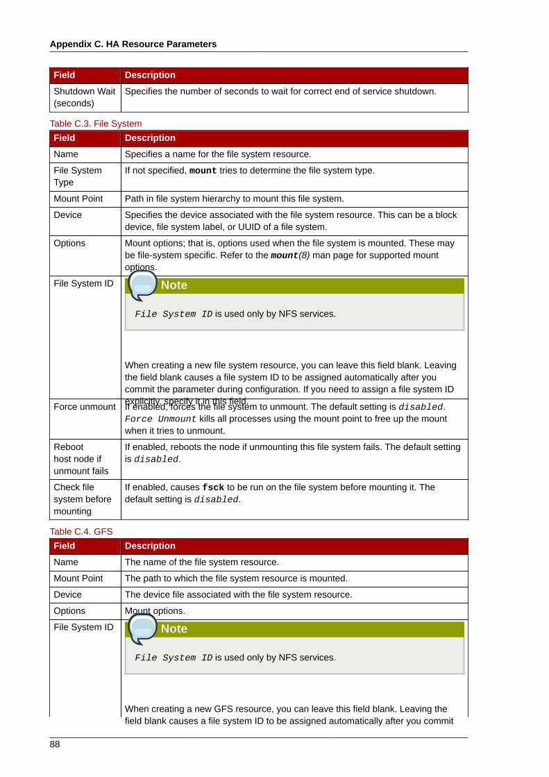
Appendix C. HA Resource Parameters
88
Field Description
Shutdown Wait(seconds)
Specifies the number of seconds to wait for correct end of service shutdown.
Table C.3. File System
Field Description
Name Specifies a name for the file system resource.
File SystemType
If not specified, mount tries to determine the file system type.
Mount Point Path in file system hierarchy to mount this file system.
Device Specifies the device associated with the file system resource. This can be a blockdevice, file system label, or UUID of a file system.
Options Mount options; that is, options used when the file system is mounted. These maybe file-system specific. Refer to the mount(8) man page for supported mountoptions.
File System ID Note
File System ID is used only by NFS services.
When creating a new file system resource, you can leave this field blank. Leavingthe field blank causes a file system ID to be assigned automatically after youcommit the parameter during configuration. If you need to assign a file system IDexplicitly, specify it in this field.Force unmount If enabled, forces the file system to unmount. The default setting is disabled.Force Unmount kills all processes using the mount point to free up the mountwhen it tries to unmount.
Reboothost node ifunmount fails
If enabled, reboots the node if unmounting this file system fails. The default settingis disabled.
Check filesystem beforemounting
If enabled, causes fsck to be run on the file system before mounting it. Thedefault setting is disabled.
Table C.4. GFS
Field Description
Name The name of the file system resource.
Mount Point The path to which the file system resource is mounted.
Device The device file associated with the file system resource.
Options Mount options.
File System ID Note
File System ID is used only by NFS services.
When creating a new GFS resource, you can leave this field blank. Leaving thefield blank causes a file system ID to be assigned automatically after you commit
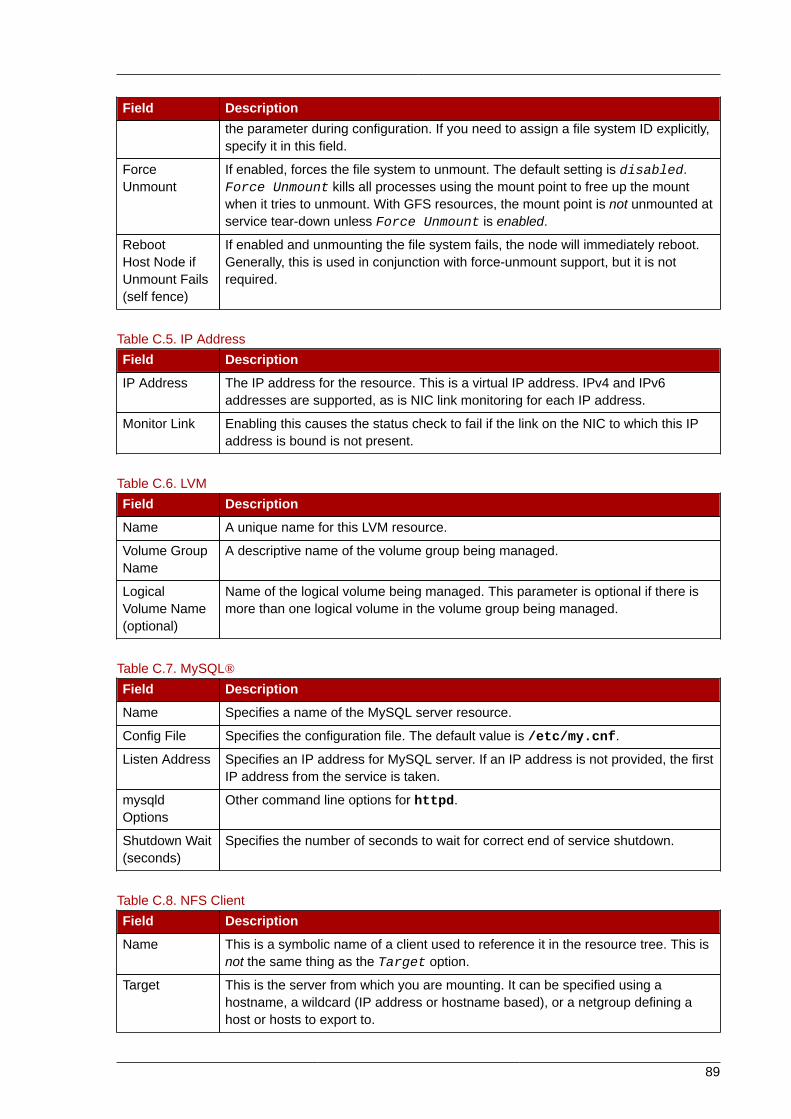
89
Field Descriptionthe parameter during configuration. If you need to assign a file system ID explicitly,specify it in this field.
ForceUnmount
If enabled, forces the file system to unmount. The default setting is disabled.Force Unmount kills all processes using the mount point to free up the mountwhen it tries to unmount. With GFS resources, the mount point is not unmounted atservice tear-down unless Force Unmount is enabled.
RebootHost Node ifUnmount Fails(self fence)
If enabled and unmounting the file system fails, the node will immediately reboot.Generally, this is used in conjunction with force-unmount support, but it is notrequired.
Table C.5. IP Address
Field Description
IP Address The IP address for the resource. This is a virtual IP address. IPv4 and IPv6addresses are supported, as is NIC link monitoring for each IP address.
Monitor Link Enabling this causes the status check to fail if the link on the NIC to which this IPaddress is bound is not present.
Table C.6. LVM
Field Description
Name A unique name for this LVM resource.
Volume GroupName
A descriptive name of the volume group being managed.
LogicalVolume Name(optional)
Name of the logical volume being managed. This parameter is optional if there ismore than one logical volume in the volume group being managed.
Table C.7. MySQL®
Field Description
Name Specifies a name of the MySQL server resource.
Config File Specifies the configuration file. The default value is /etc/my.cnf.
Listen Address Specifies an IP address for MySQL server. If an IP address is not provided, the firstIP address from the service is taken.
mysqldOptions
Other command line options for httpd.
Shutdown Wait(seconds)
Specifies the number of seconds to wait for correct end of service shutdown.
Table C.8. NFS Client
Field Description
Name This is a symbolic name of a client used to reference it in the resource tree. This isnot the same thing as the Target option.
Target This is the server from which you are mounting. It can be specified using ahostname, a wildcard (IP address or hostname based), or a netgroup defining ahost or hosts to export to.
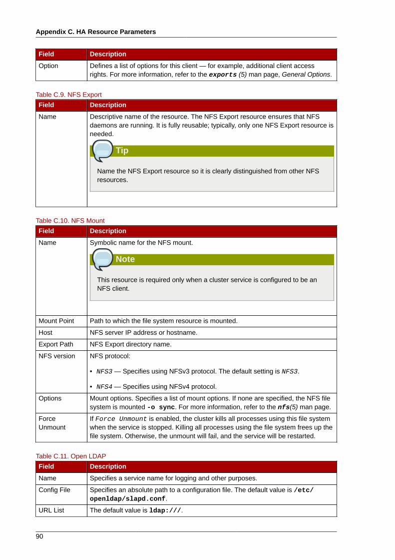
Appendix C. HA Resource Parameters
90
Field Description
Option Defines a list of options for this client — for example, additional client accessrights. For more information, refer to the exports (5) man page, General Options.
Table C.9. NFS Export
Field Description
Name Descriptive name of the resource. The NFS Export resource ensures that NFSdaemons are running. It is fully reusable; typically, only one NFS Export resource isneeded.
Tip
Name the NFS Export resource so it is clearly distinguished from other NFSresources.
Table C.10. NFS Mount
Field Description
Name Symbolic name for the NFS mount.
Note
This resource is required only when a cluster service is configured to be anNFS client.
Mount Point Path to which the file system resource is mounted.
Host NFS server IP address or hostname.
Export Path NFS Export directory name.
NFS version NFS protocol:
• NFS3 — Specifies using NFSv3 protocol. The default setting is NFS3.
• NFS4 — Specifies using NFSv4 protocol.
Options Mount options. Specifies a list of mount options. If none are specified, the NFS filesystem is mounted -o sync. For more information, refer to the nfs(5) man page.
ForceUnmount
If Force Unmount is enabled, the cluster kills all processes using this file systemwhen the service is stopped. Killing all processes using the file system frees up thefile system. Otherwise, the unmount will fail, and the service will be restarted.
Table C.11. Open LDAP
Field Description
Name Specifies a service name for logging and other purposes.
Config File Specifies an absolute path to a configuration file. The default value is /etc/openldap/slapd.conf.
URL List The default value is ldap:///.
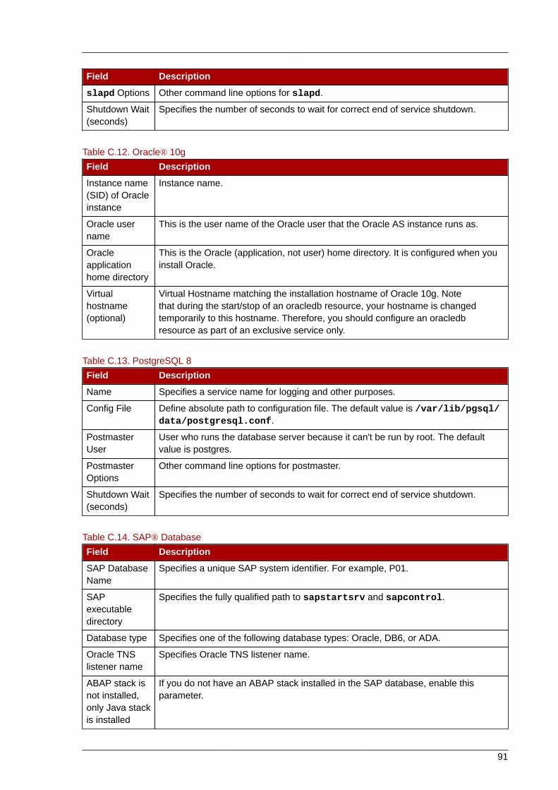
91
Field Description
slapd Options Other command line options for slapd.
Shutdown Wait(seconds)
Specifies the number of seconds to wait for correct end of service shutdown.
Table C.12. Oracle® 10g
Field Description
Instance name(SID) of Oracleinstance
Instance name.
Oracle username
This is the user name of the Oracle user that the Oracle AS instance runs as.
Oracleapplicationhome directory
This is the Oracle (application, not user) home directory. It is configured when youinstall Oracle.
Virtualhostname(optional)
Virtual Hostname matching the installation hostname of Oracle 10g. Notethat during the start/stop of an oracledb resource, your hostname is changedtemporarily to this hostname. Therefore, you should configure an oracledbresource as part of an exclusive service only.
Table C.13. PostgreSQL 8
Field Description
Name Specifies a service name for logging and other purposes.
Config File Define absolute path to configuration file. The default value is /var/lib/pgsql/data/postgresql.conf.
PostmasterUser
User who runs the database server because it can't be run by root. The defaultvalue is postgres.
PostmasterOptions
Other command line options for postmaster.
Shutdown Wait(seconds)
Specifies the number of seconds to wait for correct end of service shutdown.
Table C.14. SAP® Database
Field Description
SAP DatabaseName
Specifies a unique SAP system identifier. For example, P01.
SAPexecutabledirectory
Specifies the fully qualified path to sapstartsrv and sapcontrol.
Database type Specifies one of the following database types: Oracle, DB6, or ADA.
Oracle TNSlistener name
Specifies Oracle TNS listener name.
ABAP stack isnot installed,only Java stackis installed
If you do not have an ABAP stack installed in the SAP database, enable thisparameter.
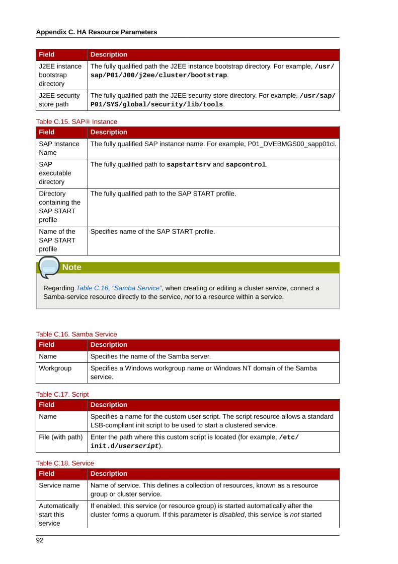
Appendix C. HA Resource Parameters
92
Field Description
J2EE instancebootstrapdirectory
The fully qualified path the J2EE instance bootstrap directory. For example, /usr/sap/P01/J00/j2ee/cluster/bootstrap.
J2EE securitystore path
The fully qualified path the J2EE security store directory. For example, /usr/sap/P01/SYS/global/security/lib/tools.
Table C.15. SAP® Instance
Field Description
SAP InstanceName
The fully qualified SAP instance name. For example, P01_DVEBMGS00_sapp01ci.
SAPexecutabledirectory
The fully qualified path to sapstartsrv and sapcontrol.
Directorycontaining theSAP STARTprofile
The fully qualified path to the SAP START profile.
Name of theSAP STARTprofile
Specifies name of the SAP START profile.
Note
Regarding Table C.16, “Samba Service”, when creating or editing a cluster service, connect aSamba-service resource directly to the service, not to a resource within a service.
Table C.16. Samba Service
Field Description
Name Specifies the name of the Samba server.
Workgroup Specifies a Windows workgroup name or Windows NT domain of the Sambaservice.
Table C.17. Script
Field Description
Name Specifies a name for the custom user script. The script resource allows a standardLSB-compliant init script to be used to start a clustered service.
File (with path) Enter the path where this custom script is located (for example, /etc/init.d/userscript).
Table C.18. Service
Field Description
Service name Name of service. This defines a collection of resources, known as a resourcegroup or cluster service.
Automaticallystart thisservice
If enabled, this service (or resource group) is started automatically after thecluster forms a quorum. If this parameter is disabled, this service is not started
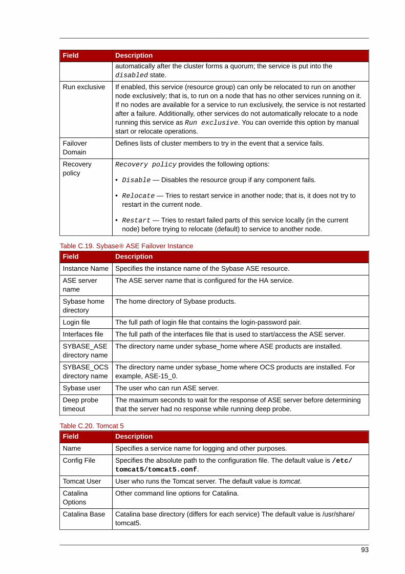
93
Field Descriptionautomatically after the cluster forms a quorum; the service is put into thedisabled state.
Run exclusive If enabled, this service (resource group) can only be relocated to run on anothernode exclusively; that is, to run on a node that has no other services running on it.If no nodes are available for a service to run exclusively, the service is not restartedafter a failure. Additionally, other services do not automatically relocate to a noderunning this service as Run exclusive. You can override this option by manualstart or relocate operations.
FailoverDomain
Defines lists of cluster members to try in the event that a service fails.
Recoverypolicy
Recovery policy provides the following options:
• Disable — Disables the resource group if any component fails.
• Relocate — Tries to restart service in another node; that is, it does not try torestart in the current node.
• Restart — Tries to restart failed parts of this service locally (in the currentnode) before trying to relocate (default) to service to another node.
Table C.19. Sybase® ASE Failover Instance
Field Description
Instance Name Specifies the instance name of the Sybase ASE resource.
ASE servername
The ASE server name that is configured for the HA service.
Sybase homedirectory
The home directory of Sybase products.
Login file The full path of login file that contains the login-password pair.
Interfaces file The full path of the interfaces file that is used to start/access the ASE server.
SYBASE_ASEdirectory name
The directory name under sybase_home where ASE products are installed.
SYBASE_OCSdirectory name
The directory name under sybase_home where OCS products are installed. Forexample, ASE-15_0.
Sybase user The user who can run ASE server.
Deep probetimeout
The maximum seconds to wait for the response of ASE server before determiningthat the server had no response while running deep probe.
Table C.20. Tomcat 5
Field Description
Name Specifies a service name for logging and other purposes.
Config File Specifies the absolute path to the configuration file. The default value is /etc/tomcat5/tomcat5.conf.
Tomcat User User who runs the Tomcat server. The default value is tomcat.
CatalinaOptions
Other command line options for Catalina.
Catalina Base Catalina base directory (differs for each service) The default value is /usr/share/tomcat5.
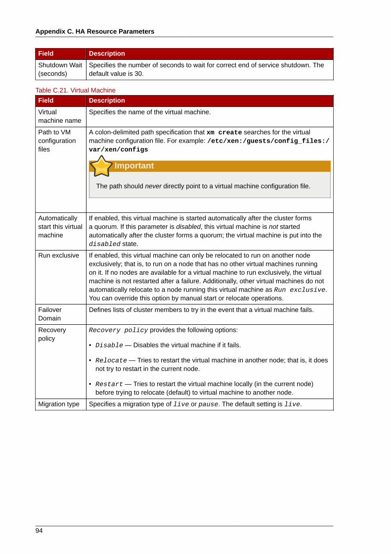
Appendix C. HA Resource Parameters
94
Field Description
Shutdown Wait(seconds)
Specifies the number of seconds to wait for correct end of service shutdown. Thedefault value is 30.
Table C.21. Virtual Machine
Field Description
Virtualmachine name
Specifies the name of the virtual machine.
Path to VMconfigurationfiles
A colon-delimited path specification that xm create searches for the virtualmachine configuration file. For example: /etc/xen:/guests/config_files:/var/xen/configs
Important
The path should never directly point to a virtual machine configuration file.
Automaticallystart this virtualmachine
If enabled, this virtual machine is started automatically after the cluster formsa quorum. If this parameter is disabled, this virtual machine is not startedautomatically after the cluster forms a quorum; the virtual machine is put into thedisabled state.
Run exclusive If enabled, this virtual machine can only be relocated to run on another nodeexclusively; that is, to run on a node that has no other virtual machines runningon it. If no nodes are available for a virtual machine to run exclusively, the virtualmachine is not restarted after a failure. Additionally, other virtual machines do notautomatically relocate to a node running this virtual machine as Run exclusive.You can override this option by manual start or relocate operations.
FailoverDomain
Defines lists of cluster members to try in the event that a virtual machine fails.
Recoverypolicy
Recovery policy provides the following options:
• Disable — Disables the virtual machine if it fails.
• Relocate — Tries to restart the virtual machine in another node; that is, it doesnot try to restart in the current node.
• Restart — Tries to restart the virtual machine locally (in the current node)before trying to relocate (default) to virtual machine to another node.
Migration type Specifies a migration type of live or pause. The default setting is live.
95
Appendix D. HA Resource BehaviorThis appendix describes common behavior of HA resources. It is meant to provide ancillaryinformation that may be helpful in configuring HA services. You can configure the parameters withLuci, system-config-cluster, or by editing etc/cluster/cluster.conf. For descriptionsof HA resource parameters, refer to Appendix C, HA Resource Parameters. To understand resourceagents in more detail you can view them in /usr/share/cluster of any cluster node.
Note
To fully comprehend the information in this appendix, you may require detailed understanding ofresource agents and the cluster configuration file, /etc/cluster/cluster.conf.
An HA service is a group of cluster resources configured into a coherent entity that providesspecialized services to clients. An HA service is represented as a resource tree in the clusterconfiguration file, /etc/cluster/cluster.conf (in each cluster node). In the cluster configurationfile, each resource tree is an XML representation that specifies each resource, its attributes, and itsrelationship among other resources in the resource tree (parent, child, and sibling relationships).
Note
Because an HA service consists of resources organized into a hierarchical tree, a service issometimes referred to as a resource tree or resource group. Both phrases are synonymous withHA service.
At the root of each resource tree is a special type of resource — a service resource. Other types ofresources comprise the rest of a service, determining its characteristics. Configuring an HA serviceconsists of creating a service resource, creating subordinate cluster resources, and organizing theminto a coherent entity that conforms to hierarchical restrictions of the service.
This appendix consists of the following sections:
• Section D.1, “Parent, Child, and Sibling Relationships Among Resources”
• Section D.2, “Sibling Start Ordering and Resource Child Ordering”
• Section D.3, “Inheritance, the <resources> Block, and Reusing Resources”
• Section D.4, “Failure Recovery and Independent Subtrees”
• Section D.5, “Debugging and Testing Services and Resource Ordering”
Note
The sections that follow present examples from the cluster configuration file, /etc/cluster/cluster.conf, for illustration purposes only.
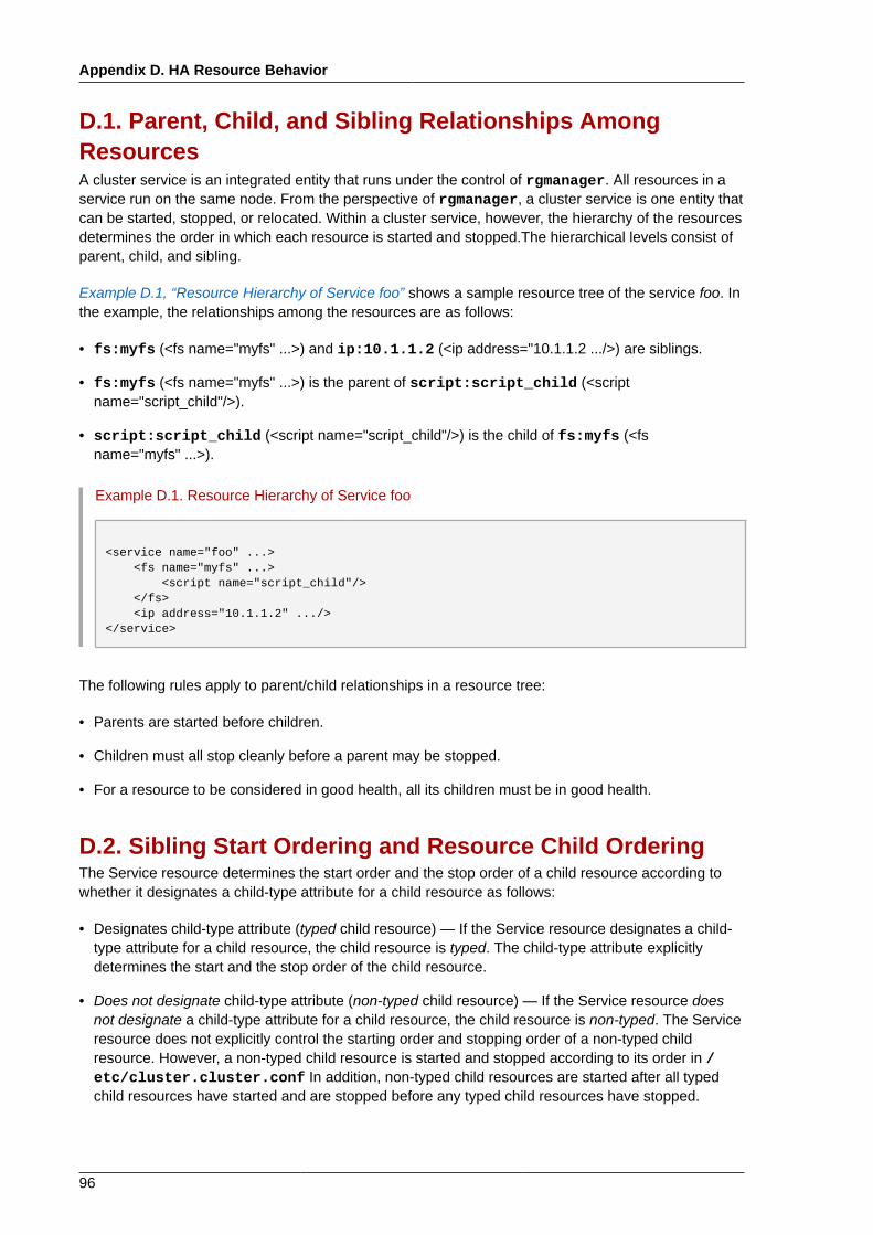
Appendix D. HA Resource Behavior
96
D.1. Parent, Child, and Sibling Relationships AmongResourcesA cluster service is an integrated entity that runs under the control of rgmanager. All resources in aservice run on the same node. From the perspective of rgmanager, a cluster service is one entity thatcan be started, stopped, or relocated. Within a cluster service, however, the hierarchy of the resourcesdetermines the order in which each resource is started and stopped.The hierarchical levels consist ofparent, child, and sibling.
Example D.1, “Resource Hierarchy of Service foo” shows a sample resource tree of the service foo. Inthe example, the relationships among the resources are as follows:
• fs:myfs (<fs name="myfs" ...>) and ip:10.1.1.2 (<ip address="10.1.1.2 .../>) are siblings.
• fs:myfs (<fs name="myfs" ...>) is the parent of script:script_child (<scriptname="script_child"/>).
• script:script_child (<script name="script_child"/>) is the child of fs:myfs (<fsname="myfs" ...>).
Example D.1. Resource Hierarchy of Service foo
<service name="foo" ...> <fs name="myfs" ...> <script name="script_child"/> </fs> <ip address="10.1.1.2" .../></service>
The following rules apply to parent/child relationships in a resource tree:
• Parents are started before children.
• Children must all stop cleanly before a parent may be stopped.
• For a resource to be considered in good health, all its children must be in good health.
D.2. Sibling Start Ordering and Resource Child OrderingThe Service resource determines the start order and the stop order of a child resource according towhether it designates a child-type attribute for a child resource as follows:
• Designates child-type attribute (typed child resource) — If the Service resource designates a child-type attribute for a child resource, the child resource is typed. The child-type attribute explicitlydetermines the start and the stop order of the child resource.
• Does not designate child-type attribute (non-typed child resource) — If the Service resource doesnot designate a child-type attribute for a child resource, the child resource is non-typed. The Serviceresource does not explicitly control the starting order and stopping order of a non-typed childresource. However, a non-typed child resource is started and stopped according to its order in /etc/cluster.cluster.conf In addition, non-typed child resources are started after all typedchild resources have started and are stopped before any typed child resources have stopped.
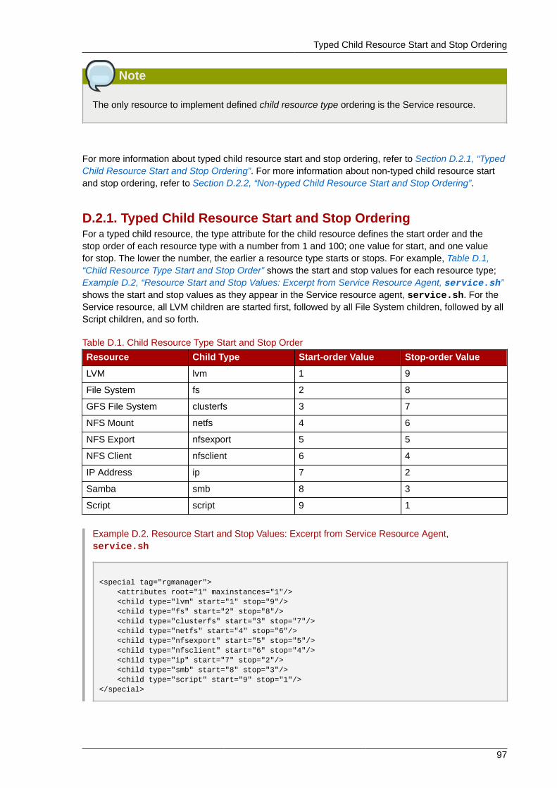
Typed Child Resource Start and Stop Ordering
97
Note
The only resource to implement defined child resource type ordering is the Service resource.
For more information about typed child resource start and stop ordering, refer to Section D.2.1, “TypedChild Resource Start and Stop Ordering”. For more information about non-typed child resource startand stop ordering, refer to Section D.2.2, “Non-typed Child Resource Start and Stop Ordering”.
D.2.1. Typed Child Resource Start and Stop OrderingFor a typed child resource, the type attribute for the child resource defines the start order and thestop order of each resource type with a number from 1 and 100; one value for start, and one valuefor stop. The lower the number, the earlier a resource type starts or stops. For example, Table D.1,“Child Resource Type Start and Stop Order” shows the start and stop values for each resource type;Example D.2, “Resource Start and Stop Values: Excerpt from Service Resource Agent, service.sh”shows the start and stop values as they appear in the Service resource agent, service.sh. For theService resource, all LVM children are started first, followed by all File System children, followed by allScript children, and so forth.
Table D.1. Child Resource Type Start and Stop Order
Resource Child Type Start-order Value Stop-order Value
LVM lvm 1 9
File System fs 2 8
GFS File System clusterfs 3 7
NFS Mount netfs 4 6
NFS Export nfsexport 5 5
NFS Client nfsclient 6 4
IP Address ip 7 2
Samba smb 8 3
Script script 9 1
Example D.2. Resource Start and Stop Values: Excerpt from Service Resource Agent,service.sh
<special tag="rgmanager"> <attributes root="1" maxinstances="1"/> <child type="lvm" start="1" stop="9"/> <child type="fs" start="2" stop="8"/> <child type="clusterfs" start="3" stop="7"/> <child type="netfs" start="4" stop="6"/> <child type="nfsexport" start="5" stop="5"/> <child type="nfsclient" start="6" stop="4"/> <child type="ip" start="7" stop="2"/> <child type="smb" start="8" stop="3"/> <child type="script" start="9" stop="1"/></special>
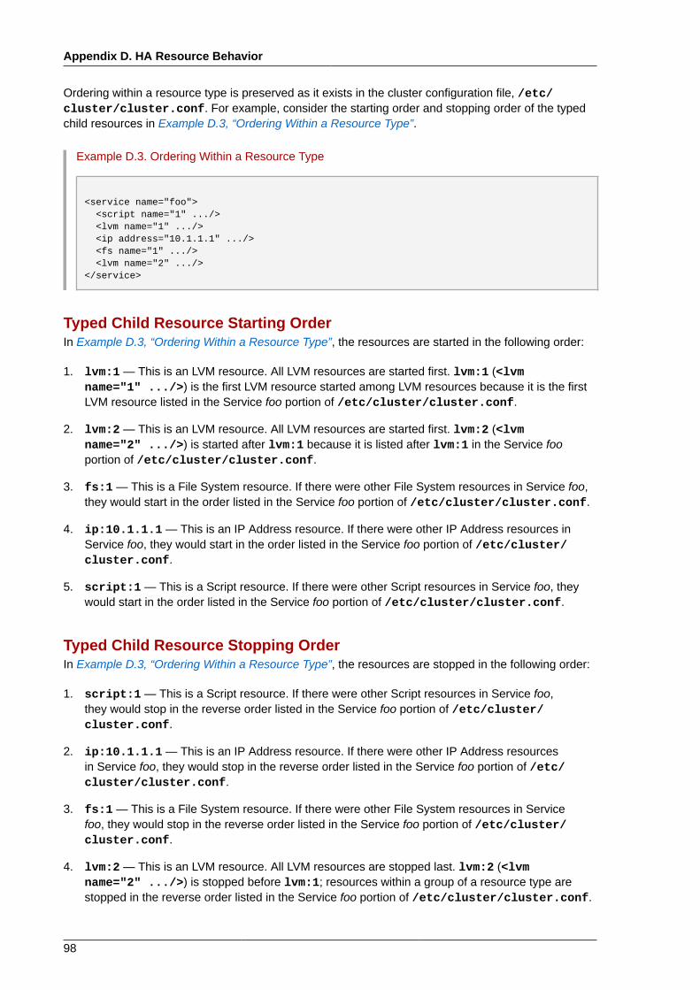
Appendix D. HA Resource Behavior
98
Ordering within a resource type is preserved as it exists in the cluster configuration file, /etc/cluster/cluster.conf. For example, consider the starting order and stopping order of the typedchild resources in Example D.3, “Ordering Within a Resource Type”.
Example D.3. Ordering Within a Resource Type
<service name="foo"> <script name="1" .../> <lvm name="1" .../> <ip address="10.1.1.1" .../> <fs name="1" .../> <lvm name="2" .../></service>
Typed Child Resource Starting OrderIn Example D.3, “Ordering Within a Resource Type”, the resources are started in the following order:
1. lvm:1 — This is an LVM resource. All LVM resources are started first. lvm:1 (<lvmname="1" .../>) is the first LVM resource started among LVM resources because it is the firstLVM resource listed in the Service foo portion of /etc/cluster/cluster.conf.
2. lvm:2 — This is an LVM resource. All LVM resources are started first. lvm:2 (<lvmname="2" .../>) is started after lvm:1 because it is listed after lvm:1 in the Service fooportion of /etc/cluster/cluster.conf.
3. fs:1 — This is a File System resource. If there were other File System resources in Service foo,they would start in the order listed in the Service foo portion of /etc/cluster/cluster.conf.
4. ip:10.1.1.1 — This is an IP Address resource. If there were other IP Address resources inService foo, they would start in the order listed in the Service foo portion of /etc/cluster/cluster.conf.
5. script:1 — This is a Script resource. If there were other Script resources in Service foo, theywould start in the order listed in the Service foo portion of /etc/cluster/cluster.conf.
Typed Child Resource Stopping OrderIn Example D.3, “Ordering Within a Resource Type”, the resources are stopped in the following order:
1. script:1 — This is a Script resource. If there were other Script resources in Service foo,they would stop in the reverse order listed in the Service foo portion of /etc/cluster/cluster.conf.
2. ip:10.1.1.1 — This is an IP Address resource. If there were other IP Address resourcesin Service foo, they would stop in the reverse order listed in the Service foo portion of /etc/cluster/cluster.conf.
3. fs:1 — This is a File System resource. If there were other File System resources in Servicefoo, they would stop in the reverse order listed in the Service foo portion of /etc/cluster/cluster.conf.
4. lvm:2 — This is an LVM resource. All LVM resources are stopped last. lvm:2 (<lvmname="2" .../>) is stopped before lvm:1; resources within a group of a resource type arestopped in the reverse order listed in the Service foo portion of /etc/cluster/cluster.conf.
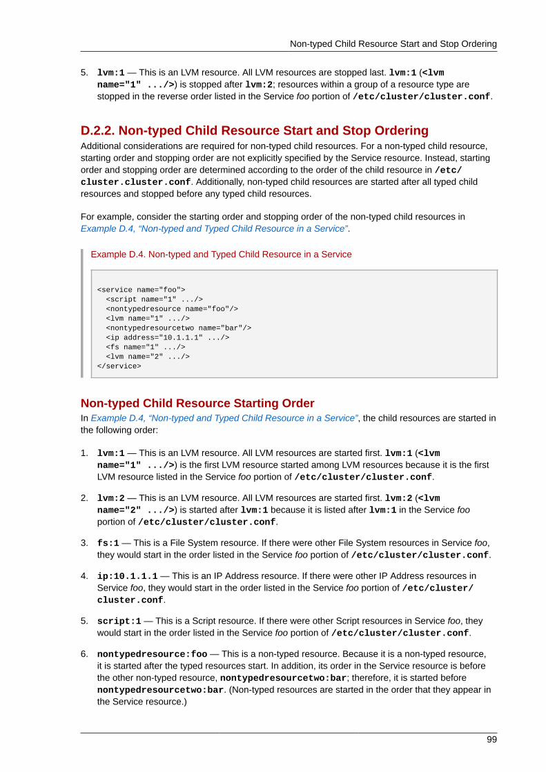
Non-typed Child Resource Start and Stop Ordering
99
5. lvm:1 — This is an LVM resource. All LVM resources are stopped last. lvm:1 (<lvmname="1" .../>) is stopped after lvm:2; resources within a group of a resource type arestopped in the reverse order listed in the Service foo portion of /etc/cluster/cluster.conf.
D.2.2. Non-typed Child Resource Start and Stop OrderingAdditional considerations are required for non-typed child resources. For a non-typed child resource,starting order and stopping order are not explicitly specified by the Service resource. Instead, startingorder and stopping order are determined according to the order of the child resource in /etc/cluster.cluster.conf. Additionally, non-typed child resources are started after all typed childresources and stopped before any typed child resources.
For example, consider the starting order and stopping order of the non-typed child resources inExample D.4, “Non-typed and Typed Child Resource in a Service”.
Example D.4. Non-typed and Typed Child Resource in a Service
<service name="foo"> <script name="1" .../> <nontypedresource name="foo"/> <lvm name="1" .../> <nontypedresourcetwo name="bar"/> <ip address="10.1.1.1" .../> <fs name="1" .../> <lvm name="2" .../></service>
Non-typed Child Resource Starting OrderIn Example D.4, “Non-typed and Typed Child Resource in a Service”, the child resources are started inthe following order:
1. lvm:1 — This is an LVM resource. All LVM resources are started first. lvm:1 (<lvmname="1" .../>) is the first LVM resource started among LVM resources because it is the firstLVM resource listed in the Service foo portion of /etc/cluster/cluster.conf.
2. lvm:2 — This is an LVM resource. All LVM resources are started first. lvm:2 (<lvmname="2" .../>) is started after lvm:1 because it is listed after lvm:1 in the Service fooportion of /etc/cluster/cluster.conf.
3. fs:1 — This is a File System resource. If there were other File System resources in Service foo,they would start in the order listed in the Service foo portion of /etc/cluster/cluster.conf.
4. ip:10.1.1.1 — This is an IP Address resource. If there were other IP Address resources inService foo, they would start in the order listed in the Service foo portion of /etc/cluster/cluster.conf.
5. script:1 — This is a Script resource. If there were other Script resources in Service foo, theywould start in the order listed in the Service foo portion of /etc/cluster/cluster.conf.
6. nontypedresource:foo — This is a non-typed resource. Because it is a non-typed resource,it is started after the typed resources start. In addition, its order in the Service resource is beforethe other non-typed resource, nontypedresourcetwo:bar; therefore, it is started beforenontypedresourcetwo:bar. (Non-typed resources are started in the order that they appear inthe Service resource.)
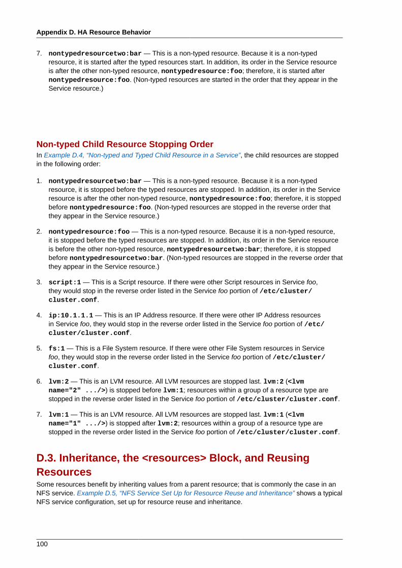
Appendix D. HA Resource Behavior
100
7. nontypedresourcetwo:bar — This is a non-typed resource. Because it is a non-typedresource, it is started after the typed resources start. In addition, its order in the Service resourceis after the other non-typed resource, nontypedresource:foo; therefore, it is started afternontypedresource:foo. (Non-typed resources are started in the order that they appear in theService resource.)
Non-typed Child Resource Stopping OrderIn Example D.4, “Non-typed and Typed Child Resource in a Service”, the child resources are stoppedin the following order:
1. nontypedresourcetwo:bar — This is a non-typed resource. Because it is a non-typedresource, it is stopped before the typed resources are stopped. In addition, its order in the Serviceresource is after the other non-typed resource, nontypedresource:foo; therefore, it is stoppedbefore nontypedresource:foo. (Non-typed resources are stopped in the reverse order thatthey appear in the Service resource.)
2. nontypedresource:foo — This is a non-typed resource. Because it is a non-typed resource,it is stopped before the typed resources are stopped. In addition, its order in the Service resourceis before the other non-typed resource, nontypedresourcetwo:bar; therefore, it is stoppedbefore nontypedresourcetwo:bar. (Non-typed resources are stopped in the reverse order thatthey appear in the Service resource.)
3. script:1 — This is a Script resource. If there were other Script resources in Service foo,they would stop in the reverse order listed in the Service foo portion of /etc/cluster/cluster.conf.
4. ip:10.1.1.1 — This is an IP Address resource. If there were other IP Address resourcesin Service foo, they would stop in the reverse order listed in the Service foo portion of /etc/cluster/cluster.conf.
5. fs:1 — This is a File System resource. If there were other File System resources in Servicefoo, they would stop in the reverse order listed in the Service foo portion of /etc/cluster/cluster.conf.
6. lvm:2 — This is an LVM resource. All LVM resources are stopped last. lvm:2 (<lvmname="2" .../>) is stopped before lvm:1; resources within a group of a resource type arestopped in the reverse order listed in the Service foo portion of /etc/cluster/cluster.conf.
7. lvm:1 — This is an LVM resource. All LVM resources are stopped last. lvm:1 (<lvmname="1" .../>) is stopped after lvm:2; resources within a group of a resource type arestopped in the reverse order listed in the Service foo portion of /etc/cluster/cluster.conf.
D.3. Inheritance, the <resources> Block, and ReusingResourcesSome resources benefit by inheriting values from a parent resource; that is commonly the case in anNFS service. Example D.5, “NFS Service Set Up for Resource Reuse and Inheritance” shows a typicalNFS service configuration, set up for resource reuse and inheritance.
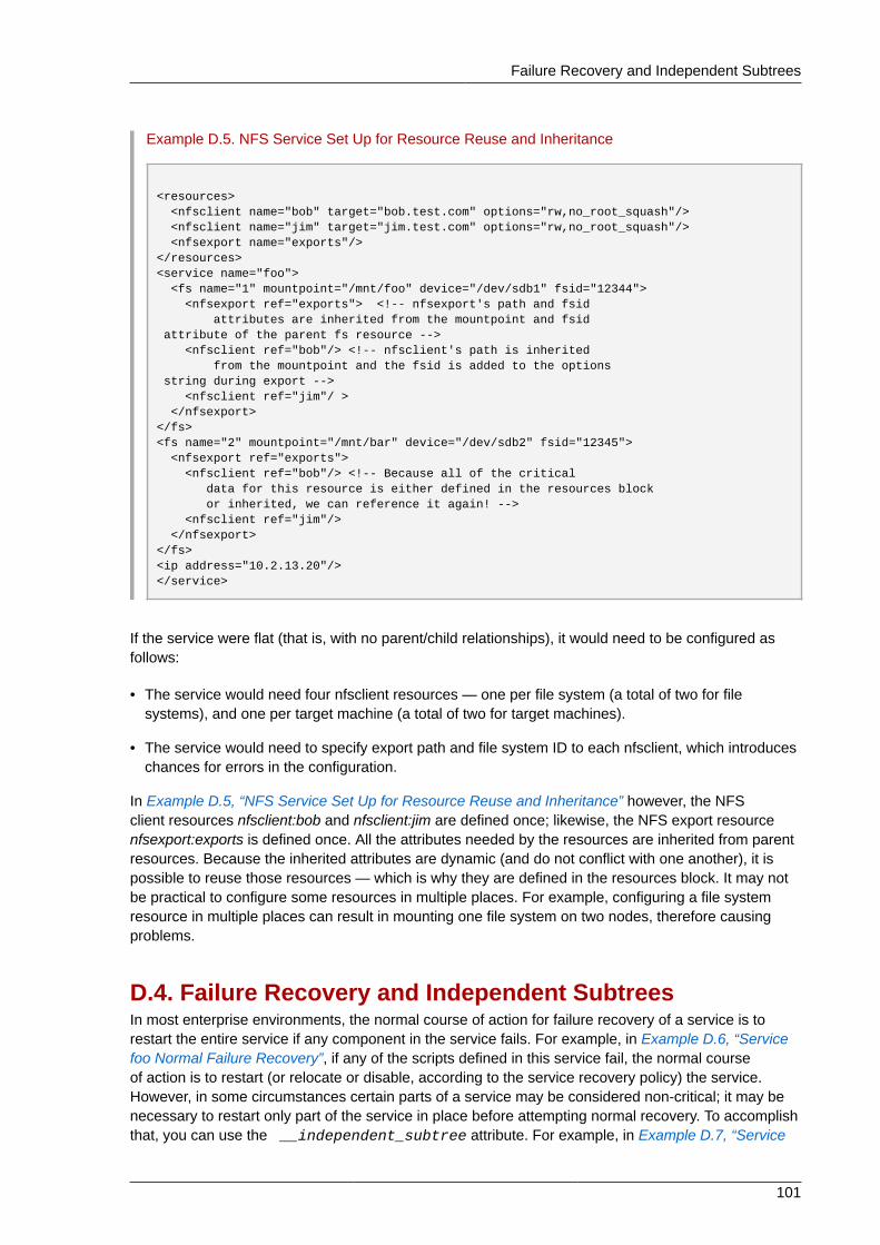
Failure Recovery and Independent Subtrees
101
Example D.5. NFS Service Set Up for Resource Reuse and Inheritance
<resources> <nfsclient name="bob" target="bob.test.com" options="rw,no_root_squash"/> <nfsclient name="jim" target="jim.test.com" options="rw,no_root_squash"/> <nfsexport name="exports"/></resources><service name="foo"> <fs name="1" mountpoint="/mnt/foo" device="/dev/sdb1" fsid="12344"> <nfsexport ref="exports"> <!-- nfsexport's path and fsid attributes are inherited from the mountpoint and fsid attribute of the parent fs resource --> <nfsclient ref="bob"/> <!-- nfsclient's path is inherited from the mountpoint and the fsid is added to the options string during export --> <nfsclient ref="jim"/ > </nfsexport></fs><fs name="2" mountpoint="/mnt/bar" device="/dev/sdb2" fsid="12345"> <nfsexport ref="exports"> <nfsclient ref="bob"/> <!-- Because all of the critical data for this resource is either defined in the resources block or inherited, we can reference it again! --> <nfsclient ref="jim"/> </nfsexport></fs><ip address="10.2.13.20"/></service>
If the service were flat (that is, with no parent/child relationships), it would need to be configured asfollows:
• The service would need four nfsclient resources — one per file system (a total of two for filesystems), and one per target machine (a total of two for target machines).
• The service would need to specify export path and file system ID to each nfsclient, which introduceschances for errors in the configuration.
In Example D.5, “NFS Service Set Up for Resource Reuse and Inheritance” however, the NFSclient resources nfsclient:bob and nfsclient:jim are defined once; likewise, the NFS export resourcenfsexport:exports is defined once. All the attributes needed by the resources are inherited from parentresources. Because the inherited attributes are dynamic (and do not conflict with one another), it ispossible to reuse those resources — which is why they are defined in the resources block. It may notbe practical to configure some resources in multiple places. For example, configuring a file systemresource in multiple places can result in mounting one file system on two nodes, therefore causingproblems.
D.4. Failure Recovery and Independent SubtreesIn most enterprise environments, the normal course of action for failure recovery of a service is torestart the entire service if any component in the service fails. For example, in Example D.6, “Servicefoo Normal Failure Recovery”, if any of the scripts defined in this service fail, the normal courseof action is to restart (or relocate or disable, according to the service recovery policy) the service.However, in some circumstances certain parts of a service may be considered non-critical; it may benecessary to restart only part of the service in place before attempting normal recovery. To accomplishthat, you can use the __independent_subtree attribute. For example, in Example D.7, “Service
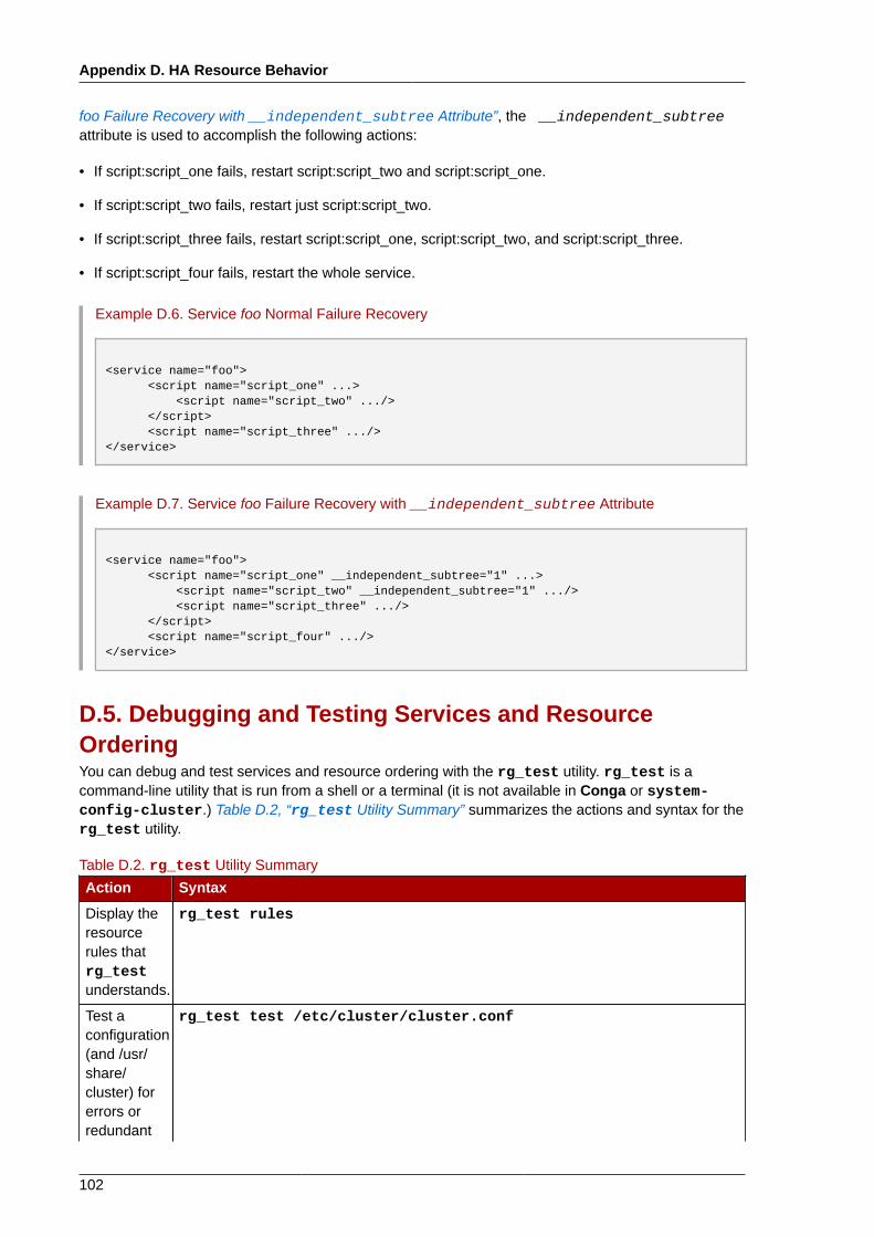
Appendix D. HA Resource Behavior
102
foo Failure Recovery with __independent_subtree Attribute”, the __independent_subtreeattribute is used to accomplish the following actions:
• If script:script_one fails, restart script:script_two and script:script_one.
• If script:script_two fails, restart just script:script_two.
• If script:script_three fails, restart script:script_one, script:script_two, and script:script_three.
• If script:script_four fails, restart the whole service.
Example D.6. Service foo Normal Failure Recovery
<service name="foo"> <script name="script_one" ...> <script name="script_two" .../> </script> <script name="script_three" .../></service>
Example D.7. Service foo Failure Recovery with __independent_subtree Attribute
<service name="foo"> <script name="script_one" __independent_subtree="1" ...> <script name="script_two" __independent_subtree="1" .../> <script name="script_three" .../> </script> <script name="script_four" .../></service>
D.5. Debugging and Testing Services and ResourceOrderingYou can debug and test services and resource ordering with the rg_test utility. rg_test is acommand-line utility that is run from a shell or a terminal (it is not available in Conga or system-config-cluster.) Table D.2, “rg_test Utility Summary” summarizes the actions and syntax for therg_test utility.
Table D.2. rg_test Utility Summary
Action Syntax
Display theresourcerules thatrg_testunderstands.
rg_test rules
Test aconfiguration(and /usr/share/cluster) forerrors orredundant
rg_test test /etc/cluster/cluster.conf
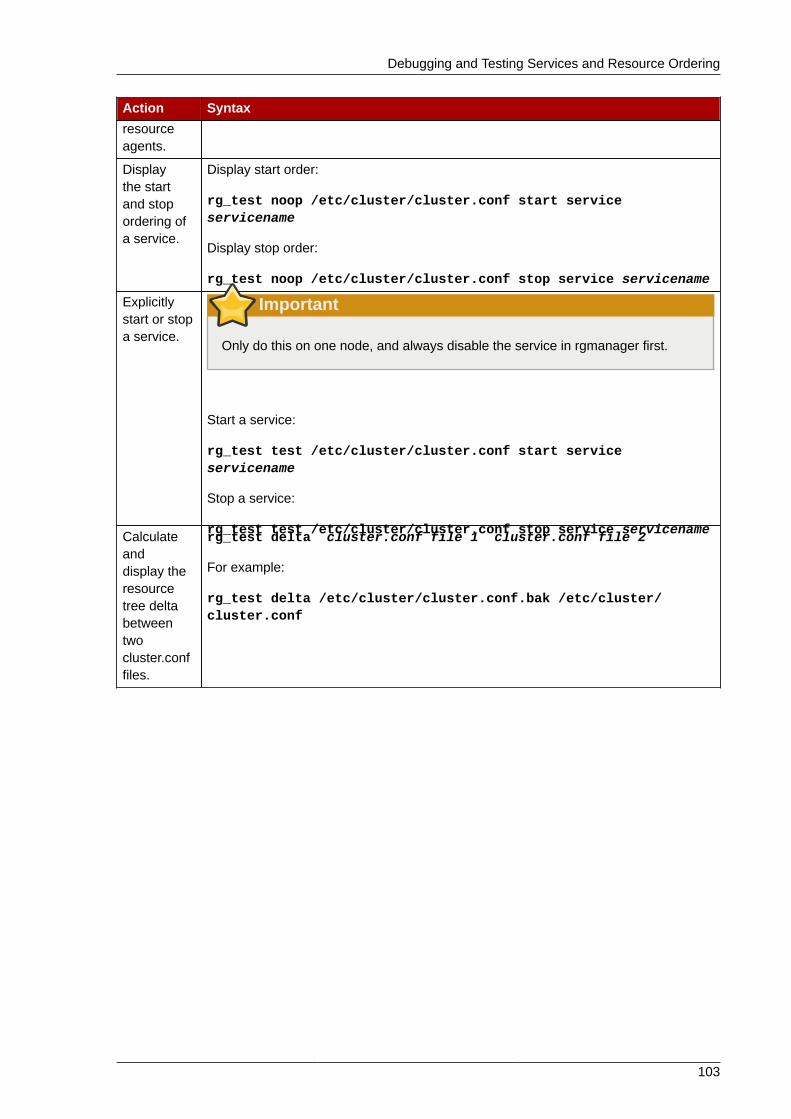
Debugging and Testing Services and Resource Ordering
103
Action Syntaxresourceagents.
Displaythe startand stopordering ofa service.
Display start order:
rg_test noop /etc/cluster/cluster.conf start serviceservicename
Display stop order:
rg_test noop /etc/cluster/cluster.conf stop service servicename
Explicitlystart or stopa service.
Important
Only do this on one node, and always disable the service in rgmanager first.
Start a service:
rg_test test /etc/cluster/cluster.conf start serviceservicename
Stop a service:
rg_test test /etc/cluster/cluster.conf stop service servicenameCalculateanddisplay theresourcetree deltabetweentwocluster.conffiles.
rg_test delta cluster.conf file 1 cluster.conf file 2
For example:
rg_test delta /etc/cluster/cluster.conf.bak /etc/cluster/cluster.conf

104
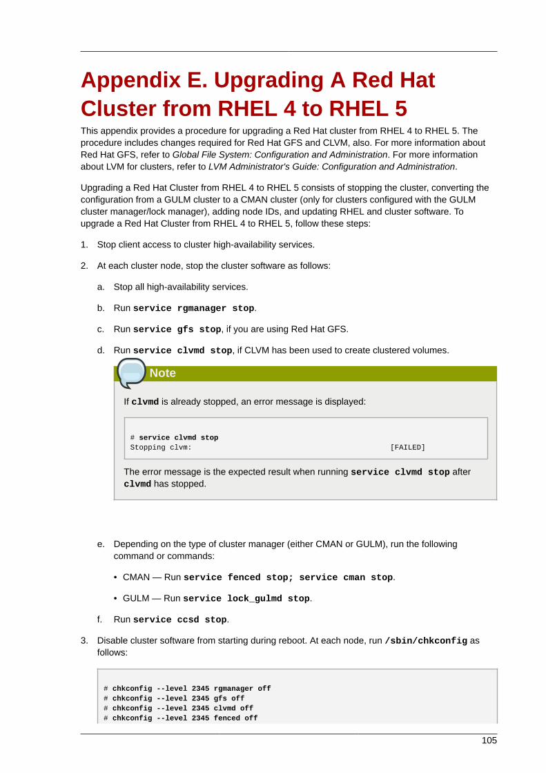
105
Appendix E. Upgrading A Red HatCluster from RHEL 4 to RHEL 5This appendix provides a procedure for upgrading a Red Hat cluster from RHEL 4 to RHEL 5. Theprocedure includes changes required for Red Hat GFS and CLVM, also. For more information aboutRed Hat GFS, refer to Global File System: Configuration and Administration. For more informationabout LVM for clusters, refer to LVM Administrator's Guide: Configuration and Administration.
Upgrading a Red Hat Cluster from RHEL 4 to RHEL 5 consists of stopping the cluster, converting theconfiguration from a GULM cluster to a CMAN cluster (only for clusters configured with the GULMcluster manager/lock manager), adding node IDs, and updating RHEL and cluster software. Toupgrade a Red Hat Cluster from RHEL 4 to RHEL 5, follow these steps:
1. Stop client access to cluster high-availability services.
2. At each cluster node, stop the cluster software as follows:
a. Stop all high-availability services.
b. Run service rgmanager stop.
c. Run service gfs stop, if you are using Red Hat GFS.
d. Run service clvmd stop, if CLVM has been used to create clustered volumes.
Note
If clvmd is already stopped, an error message is displayed:
# service clvmd stopStopping clvm: [FAILED]
The error message is the expected result when running service clvmd stop afterclvmd has stopped.
e. Depending on the type of cluster manager (either CMAN or GULM), run the followingcommand or commands:
• CMAN — Run service fenced stop; service cman stop.
• GULM — Run service lock_gulmd stop.
f. Run service ccsd stop.
3. Disable cluster software from starting during reboot. At each node, run /sbin/chkconfig asfollows:
# chkconfig --level 2345 rgmanager off# chkconfig --level 2345 gfs off# chkconfig --level 2345 clvmd off# chkconfig --level 2345 fenced off
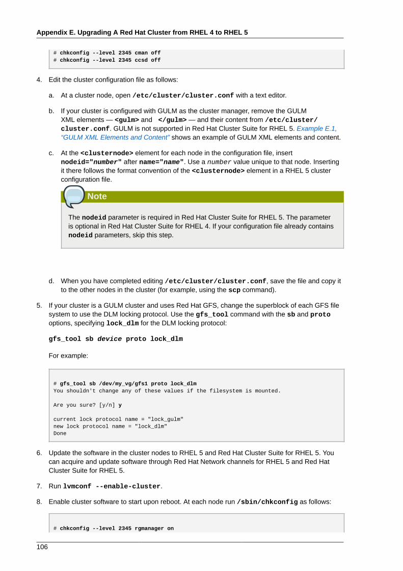
Appendix E. Upgrading A Red Hat Cluster from RHEL 4 to RHEL 5
106
# chkconfig --level 2345 cman off# chkconfig --level 2345 ccsd off
4. Edit the cluster configuration file as follows:
a. At a cluster node, open /etc/cluster/cluster.conf with a text editor.
b. If your cluster is configured with GULM as the cluster manager, remove the GULMXML elements — <gulm> and </gulm> — and their content from /etc/cluster/cluster.conf. GULM is not supported in Red Hat Cluster Suite for RHEL 5. Example E.1,“GULM XML Elements and Content” shows an example of GULM XML elements and content.
c. At the <clusternode> element for each node in the configuration file, insertnodeid="number" after name="name". Use a number value unique to that node. Insertingit there follows the format convention of the <clusternode> element in a RHEL 5 clusterconfiguration file.
Note
The nodeid parameter is required in Red Hat Cluster Suite for RHEL 5. The parameteris optional in Red Hat Cluster Suite for RHEL 4. If your configuration file already containsnodeid parameters, skip this step.
d. When you have completed editing /etc/cluster/cluster.conf, save the file and copy itto the other nodes in the cluster (for example, using the scp command).
5. If your cluster is a GULM cluster and uses Red Hat GFS, change the superblock of each GFS filesystem to use the DLM locking protocol. Use the gfs_tool command with the sb and protooptions, specifying lock_dlm for the DLM locking protocol:
gfs_tool sb device proto lock_dlm
For example:
# gfs_tool sb /dev/my_vg/gfs1 proto lock_dlmYou shouldn't change any of these values if the filesystem is mounted.
Are you sure? [y/n] y
current lock protocol name = "lock_gulm"new lock protocol name = "lock_dlm"Done
6. Update the software in the cluster nodes to RHEL 5 and Red Hat Cluster Suite for RHEL 5. Youcan acquire and update software through Red Hat Network channels for RHEL 5 and Red HatCluster Suite for RHEL 5.
7. Run lvmconf --enable-cluster.
8. Enable cluster software to start upon reboot. At each node run /sbin/chkconfig as follows:
# chkconfig --level 2345 rgmanager on
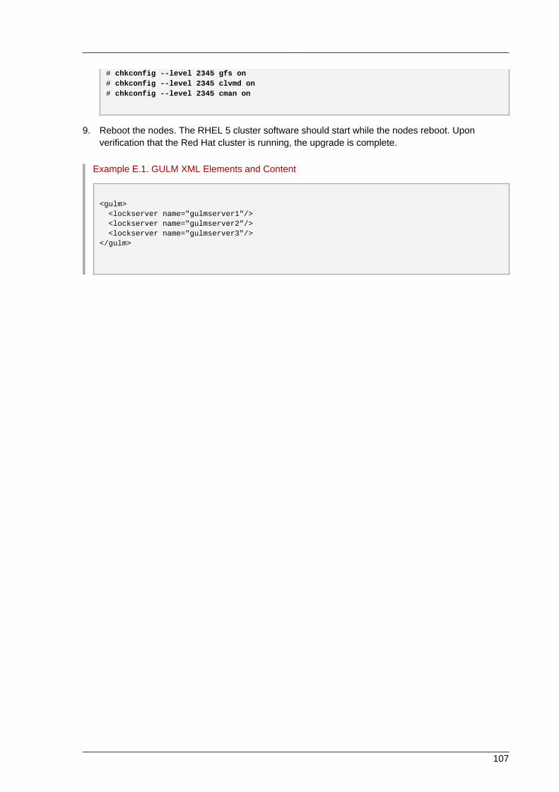
107
# chkconfig --level 2345 gfs on# chkconfig --level 2345 clvmd on# chkconfig --level 2345 cman on
9. Reboot the nodes. The RHEL 5 cluster software should start while the nodes reboot. Uponverification that the Red Hat cluster is running, the upgrade is complete.
Example E.1. GULM XML Elements and Content
<gulm> <lockserver name="gulmserver1"/> <lockserver name="gulmserver2"/> <lockserver name="gulmserver3"/></gulm>

108
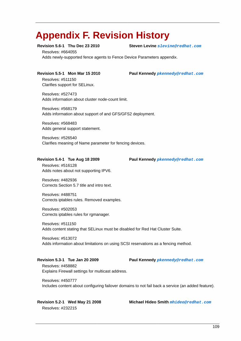
109
Appendix F. Revision HistoryRevision 5.6-1 Thu Dec 23 2010 Steven Levine [email protected]
Resolves: #664055Adds newly-supported fence agents to Fence Device Parameters appendix.
Revision 5.5-1 Mon Mar 15 2010 Paul Kennedy [email protected]: #511150Clarifies support for SELinux.
Resolves: #527473Adds information about cluster node-count limit.
Resolves: #568179Adds information about support of and GFS/GFS2 deployment.
Resolves: #568483Adds general support statement.
Resolves: #526540Clarifies meaning of Name parameter for fencing devices.
Revision 5.4-1 Tue Aug 18 2009 Paul Kennedy [email protected]: #516128Adds notes about not supporting IPV6.
Resolves: #482936Corrects Section 5.7 title and intro text.
Resolves: #488751Corrects iptables rules. Removed examples.
Resolves: #502053Corrects iptables rules for rgmanager.
Resolves: #511150Adds content stating that SELinux must be disabled for Red Hat Cluster Suite.
Resolves: #513072Adds information about limitations on using SCSI reservations as a fencing method.
Revision 5.3-1 Tue Jan 20 2009 Paul Kennedy [email protected]: #458882Explains Firewall settings for multicast address.
Resolves: #450777Includes content about configuring failover domains to not fail back a service (an added feature).
Revision 5.2-1 Wed May 21 2008 Michael Hideo Smith [email protected]: #232215

Appendix F. Revision History
110
Changing from XML to HTML Single with floating Table of Contents and viewable by browser
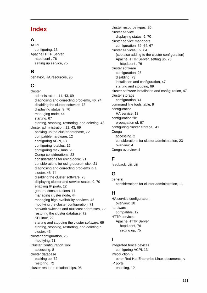
111
IndexAACPI
configuring, 13Apache HTTP Server
httpd.conf , 76setting up service, 75
Bbehavior, HA resources, 95
Ccluster
administration, 11, 43, 69diagnosing and correcting problems, 46, 74disabling the cluster software, 73displaying status, 9, 70managing node, 44starting, 67starting, stopping, restarting, and deleting, 43
cluster administration, 11, 43, 69backing up the cluster database, 72compatible hardware, 12configuring ACPI, 13configuring iptables, 12configuring max_luns, 20Conga considerations, 23considerations for using qdisk, 21considerations for using quorum disk, 21diagnosing and correcting problems in acluster, 46, 74disabling the cluster software, 73displaying cluster and service status, 9, 70enabling IP ports, 12general considerations, 11managing cluster node, 44managing high-availability services, 45modifying the cluster configuration, 71network switches and multicast addresses, 22restoring the cluster database, 72SELinux, 22starting and stopping the cluster software, 69starting, stopping, restarting, and deleting acluster, 43
cluster configuration, 25modifying, 71
Cluster Configuration Toolaccessing, 8
cluster databasebacking up, 72restoring, 72
cluster resource relationships, 96
cluster resource types, 20cluster service
displaying status, 9, 70cluster service managers
configuration, 39, 64, 67cluster services, 39, 64
(see also adding to the cluster configuration)Apache HTTP Server, setting up, 75
httpd.conf , 76cluster software
configuration, 25disabling, 73installation and configuration, 47starting and stopping, 69
cluster software installation and configuration, 47cluster storage
configuration, 41command line tools table, 9configuration
HA service, 18configuration file
propagation of, 67configuring cluster storage , 41Conga
accessing, 2considerations for cluster administration, 23overview, 4
Conga overview, 4
Ffeedback, viii, viii
Ggeneral
considerations for cluster administration, 11
HHA service configuration
overview, 18hardware
compatible, 12HTTP services
Apache HTTP Serverhttpd.conf, 76setting up, 75
Iintegrated fence devices
configuring ACPI, 13introduction, v
other Red Hat Enterprise Linux documents, vIP ports
enabling, 12
Index
112
iptablesconfiguring, 12
Mmax_luns
configuring, 20multicast addresses
considerations for using with network switchesand multicast addresses, 22
Pparameters, fence device, 79parameters, HA resources, 87power controller connection, configuring, 79power switch, 79
(see also power controller)
Qqdisk
considerations for using, 21quorum disk
considerations for using, 21
Rrelationships
cluster resource, 96
SSELinux
configuring, 22starting the cluster software, 67System V init , 69
Ttable
command line tools, 9tables
HA resources, parameters, 87power controller connection, configuring, 79
troubleshootingdiagnosing and correcting problems in acluster, 46, 74
typescluster resource, 20
Uupgrading, RHEL 4 to RHEL 5, 105


