240
Red Hat Enterprise Linux 6 Cluster Administration Configuring and Managing the High Availability Add-On

Red Hat Enterprise Linux 6Cluster Administration
Configuring and Managing the High Availability Add-On


Red Hat Enterprise Linux 6 Cluster Administrat ion
Configuring and Managing the High Availability Add-On

Legal Notice
Copyright © 2014 Red Hat, Inc. and o thers.
This document is licensed by Red Hat under the Creative Commons Attribution-ShareAlike 3.0Unported License. If you distribute this document, o r a modified version o f it, you must provideattribution to Red Hat, Inc. and provide a link to the original. If the document is modified, all RedHat trademarks must be removed.
Red Hat, as the licensor o f this document, waives the right to enforce, and agrees not to assert,Section 4d o f CC-BY-SA to the fullest extent permitted by applicable law.
Red Hat, Red Hat Enterprise Linux, the Shadowman logo, JBoss, MetaMatrix, Fedora, the InfinityLogo, and RHCE are trademarks o f Red Hat, Inc., registered in the United States and o thercountries.
Linux ® is the registered trademark o f Linus Torvalds in the United States and o ther countries.
Java ® is a registered trademark o f Oracle and/or its affiliates.
XFS ® is a trademark o f Silicon Graphics International Corp. or its subsidiaries in the UnitedStates and/or o ther countries.
MySQL ® is a registered trademark o f MySQL AB in the United States, the European Union andother countries.
Node.js ® is an o fficial trademark o f Joyent. Red Hat Software Collections is not fo rmallyrelated to or endorsed by the o fficial Joyent Node.js open source or commercial pro ject.
The OpenStack ® Word Mark and OpenStack Logo are either registered trademarks/servicemarks or trademarks/service marks o f the OpenStack Foundation, in the United States and o thercountries and are used with the OpenStack Foundation's permission. We are not affiliated with,endorsed or sponsored by the OpenStack Foundation, or the OpenStack community.
All o ther trademarks are the property o f their respective owners.
AbstractConfiguring and Managing the High Availability Add-On describes the configuration andmanagement o f the High Availability Add-On for Red Hat Enterprise Linux 6 .

. . . . . . . . . . . . . . . . . . . . . . . . . . . . . . . . . . . . . . . . . . . . . . . . . . . . . . . . . . . . . . . . . . . . . . . . . . . . . . . . . . . . . . . . . . . . . . . . . . . . . . . . . . . . . . . . . . . . . . . . . . . . . . . . . . . . . . . . . . . . . . . . . . . . . . . . . . . . . . . . . . . . . . . . . . . . . . . . . . . . . . . . . . . . . . . . . . . . . . . . . . . . . . . . . . . . . . . . . . . . . . . . . . . . . . . . . . . . . . . . . . . . . . . . . . . . . . . . . . . . . . . . . . . . . . . . . . . . . . . .
. . . . . . . . . . . . . . . . . . . . . . . . . . . . . . . . . . . . . . . . . . . . . . . . . . . . . . . . . . . . . . . . . . . . . . . . . . . . . . . . . . . . . . . . . . . . . . . . . . . . . . . . . . . . . . . . . . . . . . . . . . . . . . . . . . . . . . . . . . . . . . . . . . . . . . . . . . . . . . . . . . . . . . . . . . . . . . . . . . . . . . . . . . . . . . . . . . . . . . . . . . . . . . . . . . . . . . . . . . . . . . . . . . . . . . . . . . . . . . . . . . . . . . . . . . . . . . . . . . . . . . . . . . . . . . . . . . . . . . . .
. . . . . . . . . . . . . . . . . . . . . . . . . . . . . . . . . . . . . . . . . . . . . . . . . . . . . . . . . . . . . . . . . . . . . . . . . . . . . . . . . . . . . . . . . . . . . . . . . . . . . . . . . . . . . . . . . . . . . . . . . . . . . . . . . . . . . . . . . . . . . . . . . . . . . . . . . . . . . . . . . . . . . . . . . . . . . . . . . . . . . . . . . . . . . . . . . . . . . . . . . . . . . . . . . . . . . . . . . . . . . . . . . . . . . . . . . . . . . . . . . . . . . . . . . . . . . . . . . . . . . . . . . . . . . . . . . . . . . . . .
. . . . . . . . . . . . . . . . . . . . . . . . . . . . . . . . . . . . . . . . . . . . . . . . . . . . . . . . . . . . . . . . . . . . . . . . . . . . . . . . . . . . . . . . . . . . . . . . . . . . . . . . . . . . . . . . . . . . . . . . . . . . . . . . . . . . . . . . . . . . . . . . . . . . . . . . . . . . . . . . . . . . . . . . . . . . . . . . . . . . . . . . . . . . . . . . . . . . . . . . . . . . . . . . . . . . . . . . . . . . . . . . . . . . . . . . . . . . . . . . . . . . . . . . . . . . . . . . . . . . . . . . . . . . . . . . . . . . . . . .
. . . . . . . . . . . . . . . . . . . . . . . . . . . . . . . . . . . . . . . . . . . . . . . . . . . . . . . . . . . . . . . . . . . . . . . . . . . . . . . . . . . . . . . . . . . . . . . . . . . . . . . . . . . . . . . . . . . . . . . . . . . . . . . . . . . . . . . . . . . . . . . . . . . . . . . . . . . . . . . . . . . . . . . . . . . . . . . . . . . . . . . . . . . . . . . . . . . . . . . . . . . . . . . . . . . . . . . . . . . . . . . . . . . . . . . . . . . . . . . . . . . . . . . . . . . . . . . . . . . . . . . . . . . . . . . . . . . . . . . .
Table of Contents
Int roduct ion1. Do cument Co nventio ns1.1. Typ o g rap hic Co nventio ns1.2. Pull-q uo te Co nventio ns1.3. No tes and Warning s
2. Feed b ack
Chapt er 1 . Red Hat High Availabilit y Add- On Configurat ion and Management Overview1.1. New and Chang ed Features1.1.1. New and Chang ed Features fo r Red Hat Enterp rise Linux 6 .11.1.2. New and Chang ed Features fo r Red Hat Enterp rise Linux 6 .21.1.3. New and Chang ed Features fo r Red Hat Enterp rise Linux 6 .31.1.4. New and Chang ed Features fo r Red Hat Enterp rise Linux 6 .41.1.5. New and Chang ed Features fo r Red Hat Enterp rise Linux 6 .51.1.6 . New and Chang ed Features fo r Red Hat Enterp rise Linux 6 .6
1.2. Co nfig uratio n Basics1.3. Setting Up Hard ware1.4. Install ing Red Hat Hig h Availab il i ty Ad d -On so ftware
Upgrading Red Hat High Availabilit y Add- On Soft ware1.5. Co nfig uring Red Hat Hig h Availab il i ty Ad d -On So ftware
Chapt er 2 . Before Configuring t he Red Hat High Availabilit y Add- On2.1. General Co nfig uratio n Co nsid eratio ns2.2. Co mp atib le Hard ware2.3. Enab ling IP Po rts2.3.1. Enab ling IP Po rts o n Cluster No d es2.3.2. Enab ling the IP Po rt fo r luc i2.3.3. Co nfig uring the ip tab les Firewall to Allo w Cluster Co mp o nents
2.4. Co nfig uring luc i with /etc/sysco nfig /luc i2.5. Co nfig uring ACPI Fo r Use with Integ rated Fence Devices2.5.1. Disab ling ACPI So ft-O ff with chkco nfig Manag ement2.5.2. Disab ling ACPI So ft-O ff with the BIOS2.5.3. Disab ling ACPI Co mp letely in the g rub .co nf File
2.6 . Co nsid eratio ns fo r Co nfig uring HA Services2.7. Co nfig uratio n Valid atio n2.8 . Co nsid eratio ns fo r Netwo rkManag er2.9 . Co nsid eratio ns fo r Using Quo rum Disk2.10 . Red Hat Hig h Availab il i ty Ad d -On and SELinux2.11. Multicast Ad d resses2.12. UDP Unicast Traffic2.13. Co nsid eratio ns fo r ricc i2.14. Co nfig uring Virtual Machines in a Clustered Enviro nment
Chapt er 3. Configuring Red Hat High Availabilit y Add- On Wit h Conga3.1. Co nfig uratio n Tasks3.2. Starting luc i3.3. Co ntro ll ing Access to luc i3.4. Creating a Cluster3.5. G lo b al Cluster Pro p erties3.5.1. Co nfig uring General Pro p erties3.5.2. Co nfig uring Fence Daemo n Pro p erties3.5.3. Netwo rk Co nfig uratio n
666889
1 010101112131314141415
1 616
1 81820202020212223242426272932323434343535
363637384043434344
T able of Cont ent s
1
. . . . . . . . . . . . . . . . . . . . . . . . . . . . . . . . . . . . . . . . . . . . . . . . . . . . . . . . . . . . . . . . . . . . . . . . . . . . . . . . . . . . . . . . . . . . . . . . . . . . . . . . . . . . . . . . . . . . . . . . . . . . . . . . . . . . . . . . . . . . . . . . . . . . . . . . . . . . . . . . . . . . . . . . . . . . . . . . . . . . . . . . . . . . . . . . . . . . . . . . . . . . . . . . . . . . . . . . . . . . . . . . . . . . . . . . . . . . . . . . . . . . . . . . . . . . . . . . . . . . . . . . . . . . . . . . . . . . . . . .
. . . . . . . . . . . . . . . . . . . . . . . . . . . . . . . . . . . . . . . . . . . . . . . . . . . . . . . . . . . . . . . . . . . . . . . . . . . . . . . . . . . . . . . . . . . . . . . . . . . . . . . . . . . . . . . . . . . . . . . . . . . . . . . . . . . . . . . . . . . . . . . . . . . . . . . . . . . . . . . . . . . . . . . . . . . . . . . . . . . . . . . . . . . . . . . . . . . . . . . . . . . . . . . . . . . . . . . . . . . . . . . . . . . . . . . . . . . . . . . . . . . . . . . . . . . . . . . . . . . . . . . . . . . . . . . . . . . . . . . .
3.5.3. Netwo rk Co nfig uratio n3.5.4. Co nfig uring Red und ant Ring Pro to co l3.5.5. Quo rum Disk Co nfig uratio n3.5.6 . Lo g g ing Co nfig uratio n
3.6 . Co nfig uring Fence Devices3.6 .1. Creating a Fence Device3.6 .2. Mo d ifying a Fence Device3.6 .3. Deleting a Fence Device
3.7. Co nfig uring Fencing fo r Cluster Memb ers3.7.1. Co nfig uring a Sing le Fence Device fo r a No d e3.7.2. Co nfig uring a Backup Fence Device3.7.3. Co nfig uring a No d e with Red und ant Po wer3.7.4. Testing the Fence Co nfig uratio n
3.8 . Co nfig uring a Failo ver Do main3.8 .1. Ad d ing a Failo ver Do main3.8 .2. Mo d ifying a Failo ver Do main3.8 .3. Deleting a Failo ver Do main
3.9 . Co nfig uring G lo b al Cluster Reso urces3.10 . Ad d ing a Cluster Service to the Cluster
Chapt er 4 . Managing Red Hat High Availabilit y Add- On Wit h Conga4.1. Ad d ing an Existing Cluster to the luc i Interface4.2. Remo ving a Cluster fro m the luc i Interface4.3. Manag ing Cluster No d es4.3.1. Reb o o ting a Cluster No d e4.3.2. Causing a No d e to Leave o r Jo in a Cluster4.3.3. Ad d ing a Memb er to a Running Cluster4.3.4. Deleting a Memb er fro m a Cluster
4.4. Starting , Sto p p ing , Restarting , and Deleting Clusters4.5. Manag ing Hig h-Availab il i ty Services4.6 . Backing Up and Resto ring the luc i Co nfig uratio n
Chapt er 5. Configuring Red Hat High Availabilit y Add- On Wit h t he ccs Command5.1. Op eratio nal Overview5.1.1. Creating the Cluster Co nfig uratio n File o n a Lo cal System5.1.2. Viewing the Current Cluster Co nfig uratio n5.1.3. Sp ecifying ricc i Passwo rd s with the ccs Co mmand5.1.4. Mo d ifying Cluster Co nfig uratio n Co mp o nents5.1.5. Co mmand s that Overwrite Previo us Setting s5.1.6 . Co nfig uratio n Valid atio n
5.2. Co nfig uratio n Tasks5.3. Starting ricc i5.4. Creating and Mo d ifying a Cluster5.5. Co nfig uring Fence Devices5.6 . Lis ting Fence Devices and Fence Device Op tio ns5.7. Co nfig uring Fencing fo r Cluster Memb ers5.7.1. Co nfig uring a Sing le Po wer-Based Fence Device fo r a No d e5.7.2. Co nfig uring a Sing le Sto rag e-Based Fence Device fo r a No d e5.7.3. Co nfig uring a Backup Fence Device5.7.4. Co nfig uring a No d e with Red und ant Po wer5.7.5. Testing the Fence Co nfig uratio n5.7.6 . Remo ving Fence Metho d s and Fence Instances
5.8 . Co nfig uring a Failo ver Do main5.9 . Co nfig uring G lo b al Cluster Reso urces5.10 . Ad d ing a Cluster Service to the Cluster
44454546474848484949505152525455555556
6 06 06 06 16 16 16 26 36 36 46 5
6 76 86 86 96 96 96 97070717173757677798 18 48 78 78 79 09 0
Red Hat Ent erprise Linux 6 Clust er Administ rat ion
2

. . . . . . . . . . . . . . . . . . . . . . . . . . . . . . . . . . . . . . . . . . . . . . . . . . . . . . . . . . . . . . . . . . . . . . . . . . . . . . . . . . . . . . . . . . . . . . . . . . . . . . . . . . . . . . . . . . . . . . . . . . . . . . . . . . . . . . . . . . . . . . . . . . . . . . . . . . . . . . . . . . . . . . . . . . . . . . . . . . . . . . . . . . . . . . . . . . . . . . . . . . . . . . . . . . . . . . . . . . . . . . . . . . . . . . . . . . . . . . . . . . . . . . . . . . . . . . . . . . . . . . . . . . . . . . . . . . . . . . . .
. . . . . . . . . . . . . . . . . . . . . . . . . . . . . . . . . . . . . . . . . . . . . . . . . . . . . . . . . . . . . . . . . . . . . . . . . . . . . . . . . . . . . . . . . . . . . . . . . . . . . . . . . . . . . . . . . . . . . . . . . . . . . . . . . . . . . . . . . . . . . . . . . . . . . . . . . . . . . . . . . . . . . . . . . . . . . . . . . . . . . . . . . . . . . . . . . . . . . . . . . . . . . . . . . . . . . . . . . . . . . . . . . . . . . . . . . . . . . . . . . . . . . . . . . . . . . . . . . . . . . . . . . . . . . . . . . . . . . . . .
. . . . . . . . . . . . . . . . . . . . . . . . . . . . . . . . . . . . . . . . . . . . . . . . . . . . . . . . . . . . . . . . . . . . . . . . . . . . . . . . . . . . . . . . . . . . . . . . . . . . . . . . . . . . . . . . . . . . . . . . . . . . . . . . . . . . . . . . . . . . . . . . . . . . . . . . . . . . . . . . . . . . . . . . . . . . . . . . . . . . . . . . . . . . . . . . . . . . . . . . . . . . . . . . . . . . . . . . . . . . . . . . . . . . . . . . . . . . . . . . . . . . . . . . . . . . . . . . . . . . . . . . . . . . . . . . . . . . . . . .
. . . . . . . . . . . . . . . . . . . . . . . . . . . . . . . . . . . . . . . . . . . . . . . . . . . . . . . . . . . . . . . . . . . . . . . . . . . . . . . . . . . . . . . . . . . . . . . . . . . . . . . . . . . . . . . . . . . . . . . . . . . . . . . . . . . . . . . . . . . . . . . . . . . . . . . . . . . . . . . . . . . . . . . . . . . . . . . . . . . . . . . . . . . . . . . . . . . . . . . . . . . . . . . . . . . . . . . . . . . . . . . . . . . . . . . . . . . . . . . . . . . . . . . . . . . . . . . . . . . . . . . . . . . . . . . . . . . . . . . .
. . . . . . . . . . . . . . . . . . . . . . . . . . . . . . . . . . . . . . . . . . . . . . . . . . . . . . . . . . . . . . . . . . . . . . . . . . . . . . . . . . . . . . . . . . . . . . . . . . . . . . . . . . . . . . . . . . . . . . . . . . . . . . . . . . . . . . . . . . . . . . . . . . . . . . . . . . . . . . . . . . . . . . . . . . . . . . . . . . . . . . . . . . . . . . . . . . . . . . . . . . . . . . . . . . . . . . . . . . . . . . . . . . . . . . . . . . . . . . . . . . . . . . . . . . . . . . . . . . . . . . . . . . . . . . . . . . . . . . . .
. . . . . . . . . . . . . . . . . . . . . . . . . . . . . . . . . . . . . . . . . . . . . . . . . . . . . . . . . . . . . . . . . . . . . . . . . . . . . . . . . . . . . . . . . . . . . . . . . . . . . . . . . . . . . . . . . . . . . . . . . . . . . . . . . . . . . . . . . . . . . . . . . . . . . . . . . . . . . . . . . . . . . . . . . . . . . . . . . . . . . . . . . . . . . . . . . . . . . . . . . . . . . . . . . . . . . . . . . . . . . . . . . . . . . . . . . . . . . . . . . . . . . . . . . . . . . . . . . . . . . . . . . . . . . . . . . . . . . . . .
. . . . . . . . . . . . . . . . . . . . . . . . . . . . . . . . . . . . . . . . . . . . . . . . . . . . . . . . . . . . . . . . . . . . . . . . . . . . . . . . . . . . . . . . . . . . . . . . . . . . . . . . . . . . . . . . . . . . . . . . . . . . . . . . . . . . . . . . . . . . . . . . . . . . . . . . . . . . . . . . . . . . . . . . . . . . . . . . . . . . . . . . . . . . . . . . . . . . . . . . . . . . . . . . . . . . . . . . . . . . . . . . . . . . . . . . . . . . . . . . . . . . . . . . . . . . . . . . . . . . . . . . . . . . . . . . . . . . . . . .
. . . . . . . . . . . . . . . . . . . . . . . . . . . . . . . . . . . . . . . . . . . . . . . . . . . . . . . . . . . . . . . . . . . . . . . . . . . . . . . . . . . . . . . . . . . . . . . . . . . . . . . . . . . . . . . . . . . . . . . . . . . . . . . . . . . . . . . . . . . . . . . . . . . . . . . . . . . . . . . . . . . . . . . . . . . . . . . . . . . . . . . . . . . . . . . . . . . . . . . . . . . . . . . . . . . . . . . . . . . . . . . . . . . . . . . . . . . . . . . . . . . . . . . . . . . . . . . . . . . . . . . . . . . . . . . . . . . . . . . .
5.10 . Ad d ing a Cluster Service to the Cluster5.11. Lis ting Availab le Cluster Services and Reso urces5.12. Virtual Machine Reso urces5.13. Co nfig uring a Quo rum Disk5.14. Miscellaneo us Cluster Co nfig uratio n5.14.1. Cluster Co nfig uratio n Vers io n5.14.2. Multicast Co nfig uratio n5.14.3. Co nfig uring a Two -No d e Cluster5.14.4. Lo g g ing5.14.5. Co nfig uring Red und ant Ring Pro to co l
5.15. Pro p ag ating the Co nfig uratio n File to the Cluster No d es
Chapt er 6 . Managing Red Hat High Availabilit y Add- On Wit h ccs6 .1. Manag ing Cluster No d es6 .1.1. Causing a No d e to Leave o r Jo in a Cluster6 .1.2. Ad d ing a Memb er to a Running Cluster
6 .2. Starting and Sto p p ing a Cluster6 .3. Diag no sing and Co rrecting Pro b lems in a Cluster
Chapt er 7 . Configuring Red Hat High Availabilit y Manually7.1. Co nfig uratio n Tasks7.2. Creating a Basic Cluster Co nfig uratio n File
Basic Configurat ion Examples
T he consensus Value for t ot em in a T wo- Node Clust er7.3. Co nfig uring Fencing
Fencing Configurat ion Examples7.4. Co nfig uring Failo ver Do mains7.5. Co nfig uring HA Services7.5.1. Ad d ing Cluster Reso urces7.5.2. Ad d ing a Cluster Service to the Cluster
7.6 . Co nfig uring Red und ant Ring Pro to co l7.7. Co nfig uring Deb ug Op tio ns7.8 . Co nfig uring nfsexp o rt and nfsserver Reso urces7.9 . Verifying a Co nfig uratio n
Chapt er 8 . Managing Red Hat High Availabilit y Add- On Wit h Command Line T ools8 .1. Starting and Sto p p ing the Cluster So ftware8 .1.1. Starting Cluster So ftware8 .1.2. Sto p p ing Cluster So ftware
8 .2. Deleting o r Ad d ing a No d e8 .2.1. Deleting a No d e fro m a Cluster8 .2.2. Ad d ing a No d e to a Cluster8 .2.3. Examp les o f Three-No d e and Two -No d e Co nfig uratio ns
8 .3. Manag ing Hig h-Availab il i ty Services8 .3.1. Disp laying HA Service Status with c lustat8 .3.2. Manag ing HA Services with c lusvcad m
Considerat ions for Using t he Freeze and Unfreeze Operat ions8 .4. Up d ating a Co nfig uratio n8 .4.1. Up d ating a Co nfig uratio n Using cman_to o l vers io n -r8 .4.2. Up d ating a Co nfig uratio n Using scp
Chapt er 9 . Diagnosing and Correct ing Problems in a Clust er
9 09 39 49 59 79 79 79 89 99 9
10 0
1 0 210 210 210 210 210 3
1 0 410 510 5
1 0 7
1 0 810 9
1 1 0115118119121124125126127
1 30130131131132132136139142142143
1 4 5145146147
1 50
T able of Cont ent s
3

. . . . . . . . . . . . . . . . . . . . . . . . . . . . . . . . . . . . . . . . . . . . . . . . . . . . . . . . . . . . . . . . . . . . . . . . . . . . . . . . . . . . . . . . . . . . . . . . . . . . . . . . . . . . . . . . . . . . . . . . . . . . . . . . . . . . . . . . . . . . . . . . . . . . . . . . . . . . . . . . . . . . . . . . . . . . . . . . . . . . . . . . . . . . . . . . . . . . . . . . . . . . . . . . . . . . . . . . . . . . . . . . . . . . . . . . . . . . . . . . . . . . . . . . . . . . . . . . . . . . . . . . . . . . . . . . . . . . . . . .
. . . . . . . . . . . . . . . . . . . . . . . . . . . . . . . . . . . . . . . . . . . . . . . . . . . . . . . . . . . . . . . . . . . . . . . . . . . . . . . . . . . . . . . . . . . . . . . . . . . . . . . . . . . . . . . . . . . . . . . . . . . . . . . . . . . . . . . . . . . . . . . . . . . . . . . . . . . . . . . . . . . . . . . . . . . . . . . . . . . . . . . . . . . . . . . . . . . . . . . . . . . . . . . . . . . . . . . . . . . . . . . . . . . . . . . . . . . . . . . . . . . . . . . . . . . . . . . . . . . . . . . . . . . . . . . . . . . . . . . .
. . . . . . . . . . . . . . . . . . . . . . . . . . . . . . . . . . . . . . . . . . . . . . . . . . . . . . . . . . . . . . . . . . . . . . . . . . . . . . . . . . . . . . . . . . . . . . . . . . . . . . . . . . . . . . . . . . . . . . . . . . . . . . . . . . . . . . . . . . . . . . . . . . . . . . . . . . . . . . . . . . . . . . . . . . . . . . . . . . . . . . . . . . . . . . . . . . . . . . . . . . . . . . . . . . . . . . . . . . . . . . . . . . . . . . . . . . . . . . . . . . . . . . . . . . . . . . . . . . . . . . . . . . . . . . . . . . . . . . . .
. . . . . . . . . . . . . . . . . . . . . . . . . . . . . . . . . . . . . . . . . . . . . . . . . . . . . . . . . . . . . . . . . . . . . . . . . . . . . . . . . . . . . . . . . . . . . . . . . . . . . . . . . . . . . . . . . . . . . . . . . . . . . . . . . . . . . . . . . . . . . . . . . . . . . . . . . . . . . . . . . . . . . . . . . . . . . . . . . . . . . . . . . . . . . . . . . . . . . . . . . . . . . . . . . . . . . . . . . . . . . . . . . . . . . . . . . . . . . . . . . . . . . . . . . . . . . . . . . . . . . . . . . . . . . . . . . . . . . . . .
. . . . . . . . . . . . . . . . . . . . . . . . . . . . . . . . . . . . . . . . . . . . . . . . . . . . . . . . . . . . . . . . . . . . . . . . . . . . . . . . . . . . . . . . . . . . . . . . . . . . . . . . . . . . . . . . . . . . . . . . . . . . . . . . . . . . . . . . . . . . . . . . . . . . . . . . . . . . . . . . . . . . . . . . . . . . . . . . . . . . . . . . . . . . . . . . . . . . . . . . . . . . . . . . . . . . . . . . . . . . . . . . . . . . . . . . . . . . . . . . . . . . . . . . . . . . . . . . . . . . . . . . . . . . . . . . . . . . . . . .
. . . . . . . . . . . . . . . . . . . . . . . . . . . . . . . . . . . . . . . . . . . . . . . . . . . . . . . . . . . . . . . . . . . . . . . . . . . . . . . . . . . . . . . . . . . . . . . . . . . . . . . . . . . . . . . . . . . . . . . . . . . . . . . . . . . . . . . . . . . . . . . . . . . . . . . . . . . . . . . . . . . . . . . . . . . . . . . . . . . . . . . . . . . . . . . . . . . . . . . . . . . . . . . . . . . . . . . . . . . . . . . . . . . . . . . . . . . . . . . . . . . . . . . . . . . . . . . . . . . . . . . . . . . . . . . . . . . . . . . .
. . . . . . . . . . . . . . . . . . . . . . . . . . . . . . . . . . . . . . . . . . . . . . . . . . . . . . . . . . . . . . . . . . . . . . . . . . . . . . . . . . . . . . . . . . . . . . . . . . . . . . . . . . . . . . . . . . . . . . . . . . . . . . . . . . . . . . . . . . . . . . . . . . . . . . . . . . . . . . . . . . . . . . . . . . . . . . . . . . . . . . . . . . . . . . . . . . . . . . . . . . . . . . . . . . . . . . . . . . . . . . . . . . . . . . . . . . . . . . . . . . . . . . . . . . . . . . . . . . . . . . . . . . . . . . . . . . . . . . . .
. . . . . . . . . . . . . . . . . . . . . . . . . . . . . . . . . . . . . . . . . . . . . . . . . . . . . . . . . . . . . . . . . . . . . . . . . . . . . . . . . . . . . . . . . . . . . . . . . . . . . . . . . . . . . . . . . . . . . . . . . . . . . . . . . . . . . . . . . . . . . . . . . . . . . . . . . . . . . . . . . . . . . . . . . . . . . . . . . . . . . . . . . . . . . . . . . . . . . . . . . . . . . . . . . . . . . . . . . . . . . . . . . . . . . . . . . . . . . . . . . . . . . . . . . . . . . . . . . . . . . . . . . . . . . . . . . . . . . . . .
. . . . . . . . . . . . . . . . . . . . . . . . . . . . . . . . . . . . . . . . . . . . . . . . . . . . . . . . . . . . . . . . . . . . . . . . . . . . . . . . . . . . . . . . . . . . . . . . . . . . . . . . . . . . . . . . . . . . . . . . . . . . . . . . . . . . . . . . . . . . . . . . . . . . . . . . . . . . . . . . . . . . . . . . . . . . . . . . . . . . . . . . . . . . . . . . . . . . . . . . . . . . . . . . . . . . . . . . . . . . . . . . . . . . . . . . . . . . . . . . . . . . . . . . . . . . . . . . . . . . . . . . . . . . . . . . . . . . . . . .
. . . . . . . . . . . . . . . . . . . . . . . . . . . . . . . . . . . . . . . . . . . . . . . . . . . . . . . . . . . . . . . . . . . . . . . . . . . . . . . . . . . . . . . . . . . . . . . . . . . . . . . . . . . . . . . . . . . . . . . . . . . . . . . . . . . . . . . . . . . . . . . . . . . . . . . . . . . . . . . . . . . . . . . . . . . . . . . . . . . . . . . . . . . . . . . . . . . . . . . . . . . . . . . . . . . . . . . . . . . . . . . . . . . . . . . . . . . . . . . . . . . . . . . . . . . . . . . . . . . . . . . . . . . . . . . . . . . . . . . .
. . . . . . . . . . . . . . . . . . . . . . . . . . . . . . . . . . . . . . . . . . . . . . . . . . . . . . . . . . . . . . . . . . . . . . . . . . . . . . . . . . . . . . . . . . . . . . . . . . . . . . . . . . . . . . . . . . . . . . . . . . . . . . . . . . . . . . . . . . . . . . . . . . . . . . . . . . . . . . . . . . . . . . . . . . . . . . . . . . . . . . . . . . . . . . . . . . . . . . . . . . . . . . . . . . . . . . . . . . . . . . . . . . . . . . . . . . . . . . . . . . . . . . . . . . . . . . . . . . . . . . . . . . . . . . . . . . . . . . . .
Chapt er 9 . Diagnosing and Correct ing Problems in a Clust er9 .1. Co nfig uratio n Chang es Do No t Take Effect9 .2. Cluster Do es No t Fo rm9 .3. No d es Unab le to Rejo in Cluster after Fence o r Reb o o t9 .4. Cluster Daemo n crashes9 .4.1. Cap turing the rg manag er Co re at Runtime9 .4.2. Cap turing the Co re When the Daemo n Crashes9 .4.3. Reco rd ing a g d b Backtrace Sessio n
9 .5. Cluster Services Hang9 .6 . Cluster Service Will No t Start9 .7. Cluster-Co ntro lled Services Fails to Mig rate9 .8 . Each No d e in a Two -No d e Cluster Rep o rts Seco nd No d e Do wn9 .9 . No d es are Fenced o n LUN Path Failure9 .10 . Quo rum Disk Do es No t Ap p ear as Cluster Memb er9 .11. Unusual Failo ver Behavio r9 .12. Fencing Occurs at Rand o m9 .13. Deb ug Lo g g ing fo r Distrib uted Lo ck Manag er (DLM) Need s to b e Enab led
Chapt er 1 0 . SNMP Configurat ion wit h t he Red Hat High Availabilit y Add- On10 .1. SNMP and the Red Hat Hig h Availab il i ty Ad d -On10 .2. Co nfig uring SNMP with the Red Hat Hig h Availab il i ty Ad d -On10 .3. Fo rward ing SNMP trap s10 .4. SNMP Trap s Pro d uced b y Red Hat Hig h Availab il i ty Ad d -On
Chapt er 1 1 . Clust ered Samba Configurat ion11.1. CTDB Overview11.2. Req uired Packag es11.3. GFS2 Co nfig uratio n11.4. CTDB Co nfig uratio n11.5. Samb a Co nfig uratio n11.6 . Starting CTDB and Samb a Services11.7. Using the Clustered Samb a Server
Fence Device Paramet ers
HA Resource Paramet ers
HA Resource BehaviorC.1. Parent, Child , and Sib ling Relatio nship s Amo ng Reso urcesC.2. Sib ling Start Ord ering and Reso urce Child Ord eringC.2.1. Typ ed Child Reso urce Start and Sto p Ord ering
T yped Child Resource St art ing Order
T yped Child Resource St opping OrderC.2.2. No n-typ ed Child Reso urce Start and Sto p Ord ering
Non- t yped Child Resource St art ing Order
Non- t yped Child Resource St opping OrderC.3. Inheritance, the <reso urces> Blo ck, and Reusing Reso urcesC.4. Failure Reco very and Ind ep end ent Sub treesC.5. Deb ug g ing and Testing Services and Reso urce Ord ering
Clust er Service Resource Check and Failover T imeoutD.1. Mo d ifying the Reso urce Status Check IntervalD.2. Enfo rc ing Reso urce Timeo uts
1 50150151151152152152153154154154155155155155155156
1 57157157158158
1 6 116 116 116 116 316 516 616 7
1 6 8
1 9 1
2 0 620 620 720 8
2 0 9
2 0 9210
2 1 0
2 1 1212213214
2 1 6216216
Red Hat Ent erprise Linux 6 Clust er Administ rat ion
4

. . . . . . . . . . . . . . . . . . . . . . . . . . . . . . . . . . . . . . . . . . . . . . . . . . . . . . . . . . . . . . . . . . . . . . . . . . . . . . . . . . . . . . . . . . . . . . . . . . . . . . . . . . . . . . . . . . . . . . . . . . . . . . . . . . . . . . . . . . . . . . . . . . . . . . . . . . . . . . . . . . . . . . . . . . . . . . . . . . . . . . . . . . . . . . . . . . . . . . . . . . . . . . . . . . . . . . . . . . . . . . . . . . . . . . . . . . . . . . . . . . . . . . . . . . . . . . . . . . . . . . . . . . . . . . . . . . . . . . . .
. . . . . . . . . . . . . . . . . . . . . . . . . . . . . . . . . . . . . . . . . . . . . . . . . . . . . . . . . . . . . . . . . . . . . . . . . . . . . . . . . . . . . . . . . . . . . . . . . . . . . . . . . . . . . . . . . . . . . . . . . . . . . . . . . . . . . . . . . . . . . . . . . . . . . . . . . . . . . . . . . . . . . . . . . . . . . . . . . . . . . . . . . . . . . . . . . . . . . . . . . . . . . . . . . . . . . . . . . . . . . . . . . . . . . . . . . . . . . . . . . . . . . . . . . . . . . . . . . . . . . . . . . . . . . . . . . . . . . . . .
. . . . . . . . . . . . . . . . . . . . . . . . . . . . . . . . . . . . . . . . . . . . . . . . . . . . . . . . . . . . . . . . . . . . . . . . . . . . . . . . . . . . . . . . . . . . . . . . . . . . . . . . . . . . . . . . . . . . . . . . . . . . . . . . . . . . . . . . . . . . . . . . . . . . . . . . . . . . . . . . . . . . . . . . . . . . . . . . . . . . . . . . . . . . . . . . . . . . . . . . . . . . . . . . . . . . . . . . . . . . . . . . . . . . . . . . . . . . . . . . . . . . . . . . . . . . . . . . . . . . . . . . . . . . . . . . . . . . . . . .
. . . . . . . . . . . . . . . . . . . . . . . . . . . . . . . . . . . . . . . . . . . . . . . . . . . . . . . . . . . . . . . . . . . . . . . . . . . . . . . . . . . . . . . . . . . . . . . . . . . . . . . . . . . . . . . . . . . . . . . . . . . . . . . . . . . . . . . . . . . . . . . . . . . . . . . . . . . . . . . . . . . . . . . . . . . . . . . . . . . . . . . . . . . . . . . . . . . . . . . . . . . . . . . . . . . . . . . . . . . . . . . . . . . . . . . . . . . . . . . . . . . . . . . . . . . . . . . . . . . . . . . . . . . . . . . . . . . . . . . .
Command Line T ools Summary
High Availabilit y LVM (HA- LVM)F.1. Co nfig uring HA-LVM Failo ver with CLVM (p referred )F.2. Co nfig uring HA-LVM Failo ver with Tag g ing
Revision Hist ory
Index
2 1 8
2 1 9220221
2 2 3
2 30
T able of Cont ent s
5

Introduction
This document provides information about installing, configuring and managing Red Hat HighAvailability Add-On components. Red Hat High Availability Add-On components allow you to connecta group of computers (called nodes or members) to work together as a cluster. In this document, theuse of the word cluster or clusters is used to refer to a group of computers running the Red Hat HighAvailability Add-On.
The audience of this document should have advanced working knowledge of Red Hat EnterpriseLinux and understand the concepts of clusters, storage, and server computing.
For more information about Red Hat Enterprise Linux 6, refer to the following resources:
Red Hat Enterprise Linux Installation Guide — Provides information regarding installation of Red HatEnterprise Linux 6.
Red Hat Enterprise Linux Deployment Guide — Provides information regarding the deployment,configuration and administration of Red Hat Enterprise Linux 6.
For more information about the High Availability Add-On and related products for Red Hat EnterpriseLinux 6, refer to the following resources:
High Availability Add-On Overview — Provides a high-level overview of the Red Hat High AvailabilityAdd-On.
Logical Volume Manager Administration — Provides a description of the Logical Volume Manager(LVM), including information on running LVM in a clustered environment.
Global File System 2: Configuration and Administration — Provides information about installing,configuring, and maintaining Red Hat GFS2 (Red Hat Global File System 2), which is included inthe Resilient Storage Add-On.
DM Multipath — Provides information about using the Device-Mapper Multipath feature of Red HatEnterprise Linux 6.
Load Balancer Administration — Provides information on configuring high-performance systemsand services with the Load Balancer Add-On, a set of integrated software components thatprovide Linux Virtual Servers (LVS) for balancing IP load across a set of real servers.
Release Notes — Provides information about the current release of Red Hat products.
Red Hat Cluster Suite documentation and other Red Hat documents are available in HTML, PDF, andRPM versions on the Red Hat Enterprise Linux Documentation CD and online athttps://access.redhat.com/site/documentation/.
1. Document Convent ions
This manual uses several conventions to highlight certain words and phrases and draw attention tospecific pieces of information.
1.1. T ypographic Convent ions
Four typographic conventions are used to call attention to specific words and phrases. Theseconventions, and the circumstances they apply to, are as follows.
Mono-spaced Bold
Red Hat Ent erprise Linux 6 Clust er Administ rat ion
6

Used to highlight system input, including shell commands, file names and paths. Also used tohighlight keys and key combinations. For example:
To see the contents of the file my_next_bestselling_novel in your currentworking directory, enter the cat my_next_bestselling_novel command at theshell prompt and press Enter to execute the command.
The above includes a file name, a shell command and a key, all presented in mono-spaced bold andall distinguishable thanks to context.
Key combinations can be distinguished from an individual key by the plus sign that connects eachpart of a key combination. For example:
Press Enter to execute the command.
Press Ctrl+Alt+F2 to switch to a virtual terminal.
The first example highlights a particular key to press. The second example highlights a keycombination: a set of three keys pressed simultaneously.
If source code is discussed, class names, methods, functions, variable names and returned valuesmentioned within a paragraph will be presented as above, in mono-spaced bold . For example:
File-related classes include filesystem for file systems, file for files, and dir fordirectories. Each class has its own associated set of permissions.
Proport ional Bold
This denotes words or phrases encountered on a system, including application names; dialog-boxtext; labeled buttons; check-box and radio-button labels; menu titles and submenu titles. Forexample:
Choose System → Preferences → Mouse from the main menu bar to launchMouse Preferences . In the Buttons tab, select the Left-handed mouse checkbox and click Close to switch the primary mouse button from the left to the right(making the mouse suitable for use in the left hand).
To insert a special character into a gedit file, choose Applicat ions →Accessories → Character Map from the main menu bar. Next, choose Search →Find… from the Character Map menu bar, type the name of the character in the Search field and click Next. The character you sought will be highlighted in the Character Table. Double-click this highlighted character to place it in the Text to copy field and then click the Copy button. Now switch back to your documentand choose Edit → Paste from the gedit menu bar.
The above text includes application names; system-wide menu names and items; application-specificmenu names; and buttons and text found within a GUI interface, all presented in proportional boldand all distinguishable by context.
Mono-spaced Bold Italic or Proportional Bold Italic
Whether mono-spaced bold or proportional bold, the addition of italics indicates replaceable orvariable text. Italics denotes text you do not input literally or displayed text that changes dependingon circumstance. For example:
To connect to a remote machine using ssh, type ssh [email protected] at ashell prompt. If the remote machine is example.com and your username on thatmachine is john, type ssh [email protected].
Int roduct ion
7

The mount -o remount file-system command remounts the named file system.For example, to remount the /home file system, the command is mount -o remount /home.
To see the version of a currently installed package, use the rpm -q packagecommand. It will return a result as follows: package-version-release.
Note the words in bold italics above: username, domain.name, file-system, package, version andrelease. Each word is a placeholder, either for text you enter when issuing a command or for textdisplayed by the system.
Aside from standard usage for presenting the title of a work, italics denotes the first use of a new andimportant term. For example:
Publican is a DocBook publishing system.
1.2. Pull-quote Convent ions
Terminal output and source code listings are set off visually from the surrounding text.
Output sent to a terminal is set in mono-spaced roman and presented thus:
books Desktop documentation drafts mss photos stuff svnbooks_tests Desktop1 downloads images notes scripts svgs
Source-code listings are also set in mono-spaced roman but add syntax highlighting as follows:
static int kvm_vm_ioctl_deassign_device(struct kvm *kvm, struct kvm_assigned_pci_dev *assigned_dev){ int r = 0; struct kvm_assigned_dev_kernel *match;
mutex_lock(&kvm->lock);
match = kvm_find_assigned_dev(&kvm->arch.assigned_dev_head, assigned_dev->assigned_dev_id); if (!match) { printk(KERN_INFO "%s: device hasn't been assigned before, " "so cannot be deassigned\n", __func__); r = -EINVAL; goto out; }
kvm_deassign_device(kvm, match);
kvm_free_assigned_device(kvm, match);
out: mutex_unlock(&kvm->lock); return r;}
1.3. Notes and Warnings
Red Hat Ent erprise Linux 6 Clust er Administ rat ion
8

Finally, we use three visual styles to draw attention to information that might otherwise be overlooked.
Note
Notes are tips, shortcuts or alternative approaches to the task at hand. Ignoring a note shouldhave no negative consequences, but you might miss out on a trick that makes your life easier.
Important
Important boxes detail things that are easily missed: configuration changes that only apply tothe current session, or services that need restarting before an update will apply. Ignoring abox labeled “ Important” will not cause data loss but may cause irritation and frustration.
Warning
Warnings should not be ignored. Ignoring warnings will most likely cause data loss.
2. Feedback
If you spot a typo, or if you have thought of a way to make this manual better, we would love to hearfrom you. Please submit a report in Bugzilla: http://bugzilla.redhat.com/bugzilla/. File the bug againstthe product Red Hat Enterprise Linux 6 and the component doc-Cluster_Administ rat ion .
Be sure to mention the manual identifier:
Cluster_Administration(EN)-6 (2014-10-8T16:26)
By mentioning this manual's identifier, we know exactly which version of the guide you have.
If you have a suggestion for improving the documentation, try to be as specific as possible. If youhave found an error, please include the section number and some of the surrounding text so we canfind it easily.
Int roduct ion
9

Chapter 1. Red Hat High Availability Add-On Configuration andManagement Overview
Red Hat High Availability Add-On allows you to connect a group of computers (called nodes ormembers) to work together as a cluster. You can use Red Hat High Availability Add-On to suit yourclustering needs (for example, setting up a cluster for sharing files on a GFS2 file system or settingup service failover).
Note
For information on best practices for deploying and upgrading Red Hat Enterprise Linuxclusters using the High Availability Add-On and Red Hat Global File System 2 (GFS2) refer tothe article "Red Hat Enterprise Linux Cluster, High Availability, and GFS Deployment BestPractices" on Red Hat Customer Portal at https://access.redhat.com/site/articles/40051.
This chapter provides a summary of documentation features and updates that have been added tothe Red Hat High Availability Add-On since the initial release of Red Hat Enterprise Linux 6, followedby an overview of configuring and managing the Red Hat High Availability Add-On.
1.1. New and Changed Features
This section lists new and changed features of the Red Hat High Availability Add-On documentationthat have been added since the initial release of Red Hat Enterprise Linux 6.
1.1.1. New and Changed Features for Red Hat Enterprise Linux 6.1
Red Hat Enterprise Linux 6.1 includes the following documentation and feature updates andchanges.
As of the Red Hat Enterprise Linux 6.1 release and later, the Red Hat High Availability Add-Onprovides support for SNMP traps. For information on configuring SNMP traps with the Red HatHigh Availability Add-On, refer to Chapter 10, SNMP Configuration with the Red Hat High AvailabilityAdd-On.
As of the Red Hat Enterprise Linux 6.1 release and later, the Red Hat High Availability Add-Onprovides support for the ccs cluster configuration command. For information on the ccscommand, refer to Chapter 5, Configuring Red Hat High Availability Add-On With the ccs Command andChapter 6, Managing Red Hat High Availability Add-On With ccs.
The documentation for configuring and managing Red Hat High Availability Add-On softwareusing Conga has been updated to reflect updated Conga screens and feature support.
For the Red Hat Enterprise Linux 6.1 release and later, using ricci requires a password the firsttime you propagate updated cluster configuration from any particular node. For information on ricci refer to Section 2.13, “Considerations for ricci ” .
You can now specify a Restart-Disable failure policy for a service, indicating that the systemshould attempt to restart the service in place if it fails, but if restarting the service fails the servicewill be disabled instead of being moved to another host in the cluster. This feature is documentedin Section 3.10, “Adding a Cluster Service to the Cluster” and Appendix B, HA ResourceParameters.
Red Hat Ent erprise Linux 6 Clust er Administ rat ion
10

You can now configure an independent subtree as non-critical, indicating that if the resource failsthen only that resource is disabled. For information on this feature see Section 3.10, “Adding aCluster Service to the Cluster” and Section C.4, “Failure Recovery and Independent Subtrees” .
This document now includes the new chapter Chapter 9, Diagnosing and Correcting Problems in aCluster.
In addition, small corrections and clarifications have been made throughout the document.
1.1.2. New and Changed Features for Red Hat Enterprise Linux 6.2
Red Hat Enterprise Linux 6.2 includes the following documentation and feature updates andchanges.
Red Hat Enterprise Linux now provides support for running Clustered Samba in an active/activeconfiguration. For information on clustered Samba configuration, refer to Chapter 11, ClusteredSamba Configuration.
Any user able to authenticate on the system that is hosting luci can log in to luci . As of Red HatEnterprise Linux 6.2, only the root user on the system that is running luci can access any of theluci components until an administrator (the root user or a user with administrator permission)sets permissions for that user. For information on setting luci permissions for users, refer toSection 3.3, “Controlling Access to luci” .
The nodes in a cluster can communicate with each other using the UDP unicast transportmechanism. For information on configuring UDP unicast, refer to Section 2.12, “UDP UnicastTraffic” .
You can now configure some aspects of luci 's behavior by means of the /etc/sysconfig/luci file. For example, you can specifically configure the only IP addressluci is being served at. For information on configuring the only IP address luci is being servedat, refer to Table 2.2, “Enabled IP Port on a Computer That Runs luci” . For information on the /etc/sysconfig/luci file in general, refer to Section 2.4, “Configuring luci with /etc/sysconfig/luci ” .
The ccs command now includes the --lsfenceopts option, which prints a list of availablefence devices, and the --lsfenceopts fence_type option, which prints each available fencetype. For information on these options, refer to Section 5.6, “Listing Fence Devices and FenceDevice Options” .
The ccs command now includes the --lsserviceopts option, which prints a list of clusterservices currently available for your cluster, and the --lsserviceopts service_type option,which prints a list of the options you can specify for a particular service type. For information onthese options, refer to Section 5.11, “Listing Available Cluster Services and Resources” .
The Red Hat Enterprise Linux 6.2 release provides support for the VMware (SOAP Interface) fenceagent. For information on fence device parameters, refer to Appendix A, Fence Device Parameters.
The Red Hat Enterprise Linux 6.2 release provides support for the RHEV-M REST API fence agent,against RHEV 3.0 and later. For information on fence device parameters, refer to Appendix A,Fence Device Parameters.
As of the Red Hat Enterprise Linux 6.2 release, when you configure a virtual machine in a clusterwith the ccs command you can use the --addvm option (rather than the addservice option).This ensures that the vm resource is defined directly under the rm configuration node in the clusterconfiguration file. For information on configuring virtual machine resources with the ccscommand, refer to Section 5.12, “Virtual Machine Resources” .
Chapt er 1 . Red Hat High Availabilit y Add- On Configurat ion and Management Overview
11

This document includes a new appendix, Appendix D, Cluster Service Resource Check and FailoverTimeout. This appendix describes how rgmanager monitors the status of cluster resources, andhow to modify the status check interval. The appendix also describes the __enforce_timeoutsservice parameter, which indicates that a timeout for an operation should cause a service to fail.
This document includes a new section, Section 2.3.3, “Configuring the iptables Firewall to AllowCluster Components” . This section shows the filtering you can use to allow multicast trafficthrough the iptables firewall for the various cluster components.
In addition, small corrections and clarifications have been made throughout the document.
1.1.3. New and Changed Features for Red Hat Enterprise Linux 6.3
Red Hat Enterprise Linux 6.3 includes the following documentation and feature updates andchanges.
The Red Hat Enterprise Linux 6.3 release provides support for the condor resource agent. Forinformation on HA resource parameters, refer to Appendix B, HA Resource Parameters.
This document includes a new appendix, Appendix F, High Availability LVM (HA-LVM).
Information throughout this document clarifies which configuration changes require a clusterrestart. For a summary of these changes, refer to Section 9.1, “Configuration Changes Do NotTake Effect” .
The documentation now notes that there is an idle timeout for luci that logs you out after 15minutes of inactivity. For information on starting luci , refer to Section 3.2, “Starting luci” .
The fence_ipmilan fence device supports a privilege level parameter. For information on fencedevice parameters, refer to Appendix A, Fence Device Parameters.
This document includes a new section, Section 2.14, “Configuring Virtual Machines in a ClusteredEnvironment” .
This document includes a new section, Section 4.6, “Backing Up and Restoring the luciConfiguration” .
This document includes a new section, Section 9.4, “Cluster Daemon crashes” .
This document provides information on setting debug options in Section 5.14.4, “Logging” ,Section 7.7, “Configuring Debug Options” , and Section 9.13, “Debug Logging for DistributedLock Manager (DLM) Needs to be Enabled” .
As of Red Hat Enterprise Linux 6.3, the root user or a user who has been granted luciadministrator permissions can also use the luci interface to add users to the system, asdescribed in Section 3.3, “Controlling Access to luci” .
As of the Red Hat Enterprise Linux 6.3 release, the ccs command validates the configurationaccording to the cluster schema at /usr/share/cluster/cluster.rng on the node that youspecify with the -h option. Previously the ccs command always used the cluster schema that waspackaged with the ccs command itself, /usr/share/ccs/cluster.rng on the local system.For information on configuration validation, refer to Section 5.1.6, “Configuration Validation” .
The tables describing the fence device parameters in Appendix A, Fence Device Parameters andthe tables describing the HA resource parameters in Appendix B, HA Resource Parameters nowinclude the names of those parameters as they appear in the cluster.conf file.
In addition, small corrections and clarifications have been made throughout the document.
Red Hat Ent erprise Linux 6 Clust er Administ rat ion
12

1.1.4 . New and Changed Features for Red Hat Enterprise Linux 6.4
Red Hat Enterprise Linux 6.4 includes the following documentation and feature updates andchanges.
The Red Hat Enterprise Linux 6.4 release provides support for the Eaton Network Power Controller(SNMP Interface) fence agent, the HP BladeSystem fence agent, and the IBM iPDU fence agent.For information on fence device parameters, refer to Appendix A, Fence Device Parameters.
Appendix B, HA Resource Parameters now provides a description of the NFS Server resourceagent.
As of Red Hat Enterprise Linux 6.4, the root user or a user who has been granted luciadministrator permissions can also use the luci interface to delete users from the system. This isdocumented in Section 3.3, “Controlling Access to luci” .
Appendix B, HA Resource Parameters provides a description of the new nfsrestart parameter forthe Filesystem and GFS2 HA resources.
This document includes a new section, Section 5.1.5, “Commands that Overwrite PreviousSettings” .
Section 2.3, “Enabling IP Ports” now includes information on filtering the iptables firewall for igmp.
The IPMI LAN fence agent now supports a parameter to configure the privilege level on the IPMIdevice, as documented in Appendix A, Fence Device Parameters.
In addition to Ethernet bonding mode 1, bonding modes 0 and 2 are now supported for inter-nodecommunication in a cluster. Troubleshooting advice in this document that suggests you ensurethat you are using only supported bonding modes now notes this.
VLAN-tagged network devices are now supported for cluster heartbeat communication.Troubleshooting advice indicating that this is not supported has been removed from thisdocument.
The Red Hat High Availability Add-On now supports the configuration of redundant ring protocol.For general information on using this feature and configuring the cluster.conf configurationfile, refer to Section 7.6, “Configuring Redundant Ring Protocol” . For information on configuringredundant ring protocol with luci , refer to Section 3.5.4, “Configuring Redundant Ring Protocol” .For information on configuring redundant ring protocol with the ccs command, refer toSection 5.14.5, “Configuring Redundant Ring Protocol” .
In addition, small corrections and clarifications have been made throughout the document.
1.1.5. New and Changed Features for Red Hat Enterprise Linux 6.5
Red Hat Enterprise Linux 6.5 includes the following documentation and feature updates andchanges.
This document includes a new section, Section 7.8, “Configuring nfsexport and nfsserverResources” .
The tables of fence device parameters in Appendix A, Fence Device Parameters have been updatedto reflect small updates to the luci interface.
In addition, many small corrections and clarifications have been made throughout the document.
Chapt er 1 . Red Hat High Availabilit y Add- On Configurat ion and Management Overview
13

1.1.6. New and Changed Features for Red Hat Enterprise Linux 6.6
Red Hat Enterprise Linux 6.6 includes the following documentation and feature updates andchanges.
The tables of fence device parameters in Appendix A, Fence Device Parameters have been updatedto reflect small updates to the luci interface.
The tables of resource agent parameters in Appendix B, HA Resource Parameters have beenupdated to reflect small updates to the luci interface.
Table B.3, “Bind Mount (bind-mount Resource) (Red Hat Enterprise Linux 6.6 and later)”documents the parameters for the Bind Mount resource agent.
As of Red Hat Enterprise Linux 6.6 release, you can use the --noenable option of the ccs --startall command to prevent cluster services from being enabled, as documented inSection 6.2, “Starting and Stopping a Cluster”
Table A.11, “Fence kdump” documents the parameters for the kdump fence agent.
As of the Red Hat Enterprise Linux 6.6 release, you can sort the columns in a resource list on theluci display by clicking on the header for the sort category, as described in Section 3.9,“Configuring Global Cluster Resources” .
In addition, many small corrections and clarifications have been made throughout the document.
1.2. Configurat ion Basics
To set up a cluster, you must connect the nodes to certain cluster hardware and configure the nodesinto the cluster environment. Configuring and managing the Red Hat High Availability Add-Onconsists of the following basic steps:
1. Setting up hardware. Refer to Section 1.3, “Setting Up Hardware” .
2. Installing Red Hat High Availability Add-On software. Refer to Section 1.4, “ Installing Red HatHigh Availability Add-On software” .
3. Configuring Red Hat High Availability Add-On Software. Refer to Section 1.5, “ConfiguringRed Hat High Availability Add-On Software” .
1.3. Set t ing Up Hardware
Setting up hardware consists of connecting cluster nodes to other hardware required to run the RedHat High Availability Add-On. The amount and type of hardware varies according to the purpose andavailability requirements of the cluster. Typically, an enterprise-level cluster requires the followingtype of hardware (refer to Figure 1.1, “Red Hat High Availability Add-On Hardware Overview” ). Forconsiderations about hardware and other cluster configuration concerns, refer to Chapter 2, BeforeConfiguring the Red Hat High Availability Add-On or check with an authorized Red Hat representative.
Cluster nodes — Computers that are capable of running Red Hat Enterprise Linux 6 software, withat least 1GB of RAM.
Network switches for public network — This is required for client access to the cluster.
Network switches for private network — This is required for communication among the clusternodes and other cluster hardware such as network power switches and Fibre Channel switches.
Red Hat Ent erprise Linux 6 Clust er Administ rat ion
14

Fencing device — A fencing device is required. A network power switch is recommended toperform fencing in an enterprise-level cluster. For information about supported fencing devices,see Appendix A, Fence Device Parameters.
Storage — Some type of storage is required for a cluster. Figure 1.1, “Red Hat High AvailabilityAdd-On Hardware Overview” shows shared storage, but shared storage may not be required foryour specific use.
Figure 1.1. Red Hat High Availab ility Add-On Hardware Overview
1.4 . Installing Red Hat High Availabilit y Add-On software
To install Red Hat High Availability Add-On software, you must have entitlements for the software. Ifyou are using the luci configuration GUI, you can let it install the cluster software. If you are usingother tools to configure the cluster, secure and install the software as you would with Red HatEnterprise Linux software.
You can use the following yum install command to install the Red Hat High Availability Add-Onsoftware packages:
# yum install rgmanager lvm2-cluster gfs2-utils
Chapt er 1 . Red Hat High Availabilit y Add- On Configurat ion and Management Overview
15

Note that installing only the rgmanager will pull in all necessary dependencies to create an HAcluster from the HighAvailability channel. The lvm2-cluster and gfs2-utils packages are partof ResilientStorage channel and may not be needed by your site.
Warning
After you install the Red Hat High Availability Add-On packages, you should ensure that yoursoftware update preferences are set so that nothing is installed automatically. Installation on arunning cluster can cause unexpected behaviors.
Upgrading Red Hat High Availability Add-On Software
It is possible to upgrade the cluster software on a given major release of Red Hat Enterprise Linuxwithout taking the cluster out of production. Doing so requires disabling the cluster software on onehost at a time, upgrading the software, and restarting the cluster software on that host.
1. Shut down all cluster services on a single cluster node. For instructions on stopping clustersoftware on a node, refer to Section 8.1.2, “Stopping Cluster Software” . It may be desirable tomanually relocate cluster-managed services and virtual machines off of the host prior tostopping rgmanager.
2. Execute the yum update command to update installed packages.
3. Reboot the cluster node or restart the cluster services manually. For instructions on startingcluster software on a node, refer to Section 8.1.1, “Starting Cluster Software” .
1.5. Configuring Red Hat High Availabilit y Add-On Software
Configuring Red Hat High Availability Add-On software consists of using configuration tools tospecify the relationship among the cluster components. The following cluster configuration tools areavailable with Red Hat High Availability Add-On:
Conga — This is a comprehensive user interface for installing, configuring, and managing RedHat High Availability Add-On. Refer to Chapter 3, Configuring Red Hat High Availability Add-On WithConga and Chapter 4, Managing Red Hat High Availability Add-On With Conga for information aboutconfiguring and managing High Availability Add-On with Conga .
The ccs command — This command configures and manages Red Hat High Availability Add-On.Refer to Chapter 5, Configuring Red Hat High Availability Add-On With the ccs Command andChapter 6, Managing Red Hat High Availability Add-On With ccs for information about configuring andmanaging High Availability Add-On with the ccs command.
Command-line tools — This is a set of command-line tools for configuring and managing Red HatHigh Availability Add-On. Refer to Chapter 7, Configuring Red Hat High Availability Manually andChapter 8, Managing Red Hat High Availability Add-On With Command Line Tools for information aboutconfiguring and managing a cluster with command-line tools. Refer to Appendix E, Command LineTools Summary for a summary of preferred command-line tools.
Red Hat Ent erprise Linux 6 Clust er Administ rat ion
16

Note
system-config-cluster is not available in Red Hat Enterprise Linux 6.
Upgrading Red Hat High Availabilit y Add- On Soft ware
17

Chapter 2. Before Configuring the Red Hat High Availability Add-On
This chapter describes tasks to perform and considerations to make before installing andconfiguring the Red Hat High Availability Add-On, and consists of the following sections.
Important
Make sure that your deployment of Red Hat High Availability Add-On meets your needs andcan be supported. Consult with an authorized Red Hat representative to verify yourconfiguration prior to deployment. In addition, allow time for a configuration burn-in period totest failure modes.
Section 2.1, “General Configuration Considerations”
Section 2.2, “Compatible Hardware”
Section 2.3, “Enabling IP Ports”
Section 2.4, “Configuring luci with /etc/sysconfig/luci ”
Section 2.5, “Configuring ACPI For Use with Integrated Fence Devices”
Section 2.6, “Considerations for Configuring HA Services”
Section 2.7, “Configuration Validation”
Section 2.8, “Considerations for NetworkManager”
Section 2.9, “Considerations for Using Quorum Disk”
Section 2.10, “Red Hat High Availability Add-On and SELinux”
Section 2.11, “Multicast Addresses”
Section 2.12, “UDP Unicast Traffic”
Section 2.13, “Considerations for ricci ”
Section 2.14, “Configuring Virtual Machines in a Clustered Environment”
2.1. General Configurat ion Considerat ions
You can configure the Red Hat High Availability Add-On in a variety of ways to suit your needs. Takeinto account the following general considerations when you plan, configure, and implement yourdeployment.
Number of cluster nodes supported
The maximum number of cluster nodes supported by the High Availability Add-On is 16.
Single site clusters
Red Hat Ent erprise Linux 6 Clust er Administ rat ion
18

Only single site clusters are fully supported at this time. Clusters spread across multiplephysical locations are not formally supported. For more details and to discuss multi-siteclusters, please speak to your Red Hat sales or support representative.
GFS2
Although a GFS2 file system can be implemented in a standalone system or as part of acluster configuration, Red Hat does not support the use of GFS2 as a single-node filesystem. Red Hat does support a number of high-performance single-node file systems thatare optimized for single node, which have generally lower overhead than a cluster filesystem. Red Hat recommends using those file systems in preference to GFS2 in cases whereonly a single node needs to mount the file system. Red Hat will continue to support single-node GFS2 file systems for existing customers.
When you configure a GFS2 file system as a cluster file system, you must ensure that allnodes in the cluster have access to the shared file system. Asymmetric clusterconfigurations in which some nodes have access to the file system and others do not arenot supported.This does not require that all nodes actually mount the GFS2 file systemitself.
No-single-point -of - failure hardware conf igurat ion
Clusters can include a dual-controller RAID array, multiple bonded network channels,multiple paths between cluster members and storage, and redundant un-interruptible powersupply (UPS) systems to ensure that no single failure results in application down time orloss of data.
Alternatively, a low-cost cluster can be set up to provide less availability than a no-single-point-of-failure cluster. For example, you can set up a cluster with a single-controller RAIDarray and only a single Ethernet channel.
Certain low-cost alternatives, such as host RAID controllers, software RAID without clustersupport, and multi-initiator parallel SCSI configurations are not compatible or appropriatefor use as shared cluster storage.
Data in tegrity assurance
To ensure data integrity, only one node can run a cluster service and access cluster-service data at a time. The use of power switches in the cluster hardware configurationenables a node to power-cycle another node before restarting that node's HA servicesduring a failover process. This prevents two nodes from simultaneously accessing thesame data and corrupting it. Fence devices (hardware or software solutions that remotelypower, shutdown, and reboot cluster nodes) are used to guarantee data integrity under allfailure conditions.
Ethernet channel bonding
Cluster quorum and node health is determined by communication of messages amongcluster nodes via Ethernet. In addition, cluster nodes use Ethernet for a variety of othercritical cluster functions (for example, fencing). With Ethernet channel bonding, multipleEthernet interfaces are configured to behave as one, reducing the risk of a single-point-of-failure in the typical switched Ethernet connection among cluster nodes and other clusterhardware.
As of Red Hat Enterprise Linux 6.4, bonding modes 0, 1, and 2 are supported.
IPv4 and IPv6
Chapt er 2 . Before Configuring t he Red Hat High Availabilit y Add- On
19

The High Availability Add-On supports both IPv4 and IPv6 Internet Protocols. Support ofIPv6 in the High Availability Add-On is new for Red Hat Enterprise Linux 6.
2.2. Compat ible Hardware
Before configuring Red Hat High Availability Add-On software, make sure that your cluster usesappropriate hardware (for example, supported fence devices, storage devices, and Fibre Channelswitches). Refer to the Red Hat Hardware Catalog at https://hardware.redhat.com/ for the most currenthardware compatibility information.
2.3. Enabling IP Ports
Before deploying the Red Hat High Availability Add-On, you must enable certain IP ports on thecluster nodes and on computers that run luci (the Conga user interface server). The followingsections identify the IP ports to be enabled:
Section 2.3.1, “Enabling IP Ports on Cluster Nodes”
Section 2.3.2, “Enabling the IP Port for luci”
The following section provides the iptables rules for enabling IP ports needed by the Red Hat HighAvailability Add-On:
Section 2.3.3, “Configuring the iptables Firewall to Allow Cluster Components”
2.3.1. Enabling IP Ports on Cluster Nodes
To allow the nodes in a cluster to communicate with each other, you must enable the IP portsassigned to certain Red Hat High Availability Add-On components. Table 2.1, “Enabled IP Ports onRed Hat High Availability Add-On Nodes” lists the IP port numbers, their respective protocols, and thecomponents to which the port numbers are assigned. At each cluster node, enable IP ports forincoming traffic according to Table 2.1, “Enabled IP Ports on Red Hat High Availability Add-OnNodes” . You can use system-config-firewall to enable the IP ports.
Table 2.1. Enabled IP Ports on Red Hat High Availab ility Add-On Nodes
IP Port Number Protocol Component5404, 5405 UDP corosync/cman (Cluster Manager)11111 TCP ricci (propagates updated cluster information)21064 TCP dlm (Distributed Lock Manager)16851 TCP modclusterd
2.3.2. Enabling the IP Port for luci
To allow client computers to communicate with a computer that runs luci (the Conga user interfaceserver), you must enable the IP port assigned to luci . At each computer that runs luci , enable the IPport according to Table 2.2, “Enabled IP Port on a Computer That Runs luci” .
Note
If a cluster node is running luci , port 11111 should already have been enabled.
Red Hat Ent erprise Linux 6 Clust er Administ rat ion
20

Table 2.2. Enabled IP Port on a Computer That Runs luci
IP Port Number Protocol Component8084 TCP luci (Conga user interface server)
As of the Red Hat Enterprise Linux 6.1 release, which enabled configuration by means of the /etc/sysconfig/luci file, you can specifically configure the only IP address luci is beingserved at. You can use this capability if your server infrastructure incorporates more than onenetwork and you want to access luci from the internal network only. To do this, uncomment and editthe line in the file that specifies host. For example, to change the host setting in the file to10.10.10.10, edit the host line as follows:
host = 10.10.10.10
For more information on the /etc/sysconfig/luci file, refer to Section 2.4, “Configuring luciwith /etc/sysconfig/luci ” .
2.3.3. Configuring the iptables Firewall to Allow Cluster Components
Listed below are example iptable rules for enabling IP ports needed by Red Hat Enterprise Linux 6(with High Availability Add-on). Please note that these examples use 192.168.1.0/24 as a subnet, butyou will need to replace 192.168.1.0/24 with the appropriate subnet if you use these rules.
For cman (Cluster Manager), use the following filtering.
$ iptables -I INPUT -m state --state NEW -m multiport -p udp -s 192.168.1.0/24 -d 192.168.1.0/24 --dports 5404,5405 -j ACCEPT$ iptables -I INPUT -m addrtype --dst-type MULTICAST -m state --state NEW -m multiport -p udp -s 192.168.1.0/24 --dports 5404,5405 -j ACCEPT
For dlm (Distributed Lock Manager):
$ iptables -I INPUT -m state --state NEW -p tcp -s 192.168.1.0/24 -d 192.168.1.0/24 --dport 21064 -j ACCEPT
For ricci (part of Conga remote agent):
$ iptables -I INPUT -m state --state NEW -p tcp -s 192.168.1.0/24 -d 192.168.1.0/24 --dport 11111 -j ACCEPT
For modclusterd (part of Conga remote agent):
$ iptables -I INPUT -m state --state NEW -p tcp -s 192.168.1.0/24 -d 192.168.1.0/24 --dport 16851 -j ACCEPT
For luci (Conga User Interface server):
$ iptables -I INPUT -m state --state NEW -p tcp -s 192.168.1.0/24 -d 192.168.1.0/24 --dport 8084 -j ACCEPT
For igmp (Internet Group Management Protocol):
$ iptables -I INPUT -p igmp -j ACCEPT
Chapt er 2 . Before Configuring t he Red Hat High Availabilit y Add- On
21
After executing these commands, run the following command to save the current configuration for thechanges to be persistent during reboot.
$ service iptables save ; service iptables restart
2.4 . Configuring luci with /etc/sysconfig/luci
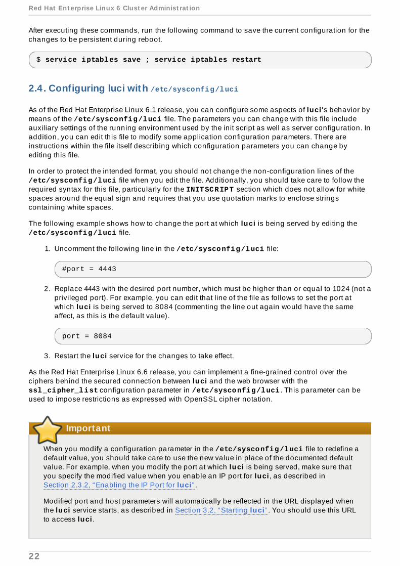
As of the Red Hat Enterprise Linux 6.1 release, you can configure some aspects of luci 's behavior bymeans of the /etc/sysconfig/luci file. The parameters you can change with this file includeauxiliary settings of the running environment used by the init script as well as server configuration. Inaddition, you can edit this file to modify some application configuration parameters. There areinstructions within the file itself describing which configuration parameters you can change byediting this file.
In order to protect the intended format, you should not change the non-configuration lines of the /etc/sysconfig/luci file when you edit the file. Additionally, you should take care to follow therequired syntax for this file, particularly for the INITSCRIPT section which does not allow for whitespaces around the equal sign and requires that you use quotation marks to enclose stringscontaining white spaces.
The following example shows how to change the port at which luci is being served by editing the /etc/sysconfig/luci file.
1. Uncomment the following line in the /etc/sysconfig/luci file:
#port = 4443
2. Replace 4443 with the desired port number, which must be higher than or equal to 1024 (not aprivileged port). For example, you can edit that line of the file as follows to set the port atwhich luci is being served to 8084 (commenting the line out again would have the sameaffect, as this is the default value).
port = 8084
3. Restart the luci service for the changes to take effect.
As the Red Hat Enterprise Linux 6.6 release, you can implement a fine-grained control over theciphers behind the secured connection between luci and the web browser with the ssl_cipher_list configuration parameter in /etc/sysconfig/luci . This parameter can beused to impose restrictions as expressed with OpenSSL cipher notation.
Important
When you modify a configuration parameter in the /etc/sysconfig/luci file to redefine adefault value, you should take care to use the new value in place of the documented defaultvalue. For example, when you modify the port at which luci is being served, make sure thatyou specify the modified value when you enable an IP port for luci , as described inSection 2.3.2, “Enabling the IP Port for luci” .
Modified port and host parameters will automatically be reflected in the URL displayed whenthe luci service starts, as described in Section 3.2, “Starting luci” . You should use this URLto access luci .
Red Hat Ent erprise Linux 6 Clust er Administ rat ion
22
For more complete information on the parameters you can configure with the /etc/sysconfig/luci file, refer to the documentation within the file itself.
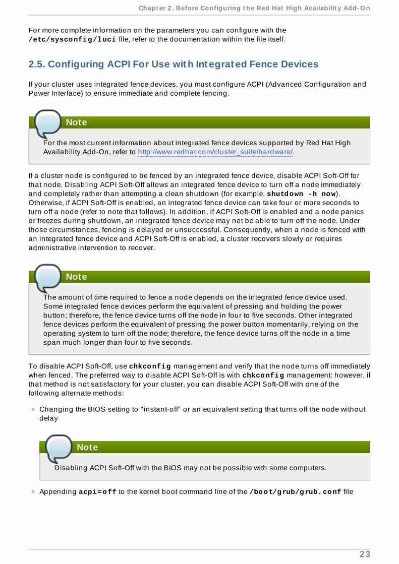
2.5. Configuring ACPI For Use with Integrated Fence Devices
If your cluster uses integrated fence devices, you must configure ACPI (Advanced Configuration andPower Interface) to ensure immediate and complete fencing.
Note
For the most current information about integrated fence devices supported by Red Hat HighAvailability Add-On, refer to http://www.redhat.com/cluster_suite/hardware/.
If a cluster node is configured to be fenced by an integrated fence device, disable ACPI Soft-Off forthat node. Disabling ACPI Soft-Off allows an integrated fence device to turn off a node immediatelyand completely rather than attempting a clean shutdown (for example, shutdown -h now).Otherwise, if ACPI Soft-Off is enabled, an integrated fence device can take four or more seconds toturn off a node (refer to note that follows). In addition, if ACPI Soft-Off is enabled and a node panicsor freezes during shutdown, an integrated fence device may not be able to turn off the node. Underthose circumstances, fencing is delayed or unsuccessful. Consequently, when a node is fenced withan integrated fence device and ACPI Soft-Off is enabled, a cluster recovers slowly or requiresadministrative intervention to recover.
Note
The amount of time required to fence a node depends on the integrated fence device used.Some integrated fence devices perform the equivalent of pressing and holding the powerbutton; therefore, the fence device turns off the node in four to five seconds. Other integratedfence devices perform the equivalent of pressing the power button momentarily, relying on theoperating system to turn off the node; therefore, the fence device turns off the node in a timespan much longer than four to five seconds.
To disable ACPI Soft-Off, use chkconfig management and verify that the node turns off immediatelywhen fenced. The preferred way to disable ACPI Soft-Off is with chkconfig management: however, ifthat method is not satisfactory for your cluster, you can disable ACPI Soft-Off with one of thefollowing alternate methods:
Changing the BIOS setting to " instant-off" or an equivalent setting that turns off the node withoutdelay
Note
Disabling ACPI Soft-Off with the BIOS may not be possible with some computers.
Appending acpi=off to the kernel boot command line of the /boot/grub/grub.conf file
Chapt er 2 . Before Configuring t he Red Hat High Availabilit y Add- On
23

Important
This method completely disables ACPI; some computers do not boot correctly if ACPI iscompletely disabled. Use this method only if the other methods are not effective for yourcluster.
The following sections provide procedures for the preferred method and alternate methods ofdisabling ACPI Soft-Off:
Section 2.5.1, “Disabling ACPI Soft-Off with chkconfig Management” — Preferred method
Section 2.5.2, “Disabling ACPI Soft-Off with the BIOS” — First alternate method
Section 2.5.3, “Disabling ACPI Completely in the grub.conf File” — Second alternate method
2.5.1. Disabling ACPI Soft -Off with chkconfig Management
You can use chkconfig management to disable ACPI Soft-Off either by removing the ACPI daemon(acpid ) from chkconfig management or by turning off acpid .
Note
This is the preferred method of disabling ACPI Soft-Off.
Disable ACPI Soft-Off with chkconfig management at each cluster node as follows:
1. Run either of the following commands:
chkconfig --del acpid — This command removes acpid from chkconfigmanagement.
— OR —
chkconfig --level 345 acpid off — This command turns off acpid .
2. Reboot the node.
3. When the cluster is configured and running, verify that the node turns off immediately whenfenced.
Note
You can fence the node with the fence_node command or Conga .
2.5.2. Disabling ACPI Soft -Off with the BIOS
The preferred method of disabling ACPI Soft-Off is with chkconfig management (Section 2.5.1,“Disabling ACPI Soft-Off with chkconfig Management” ). However, if the preferred method is noteffective for your cluster, follow the procedure in this section.
Red Hat Ent erprise Linux 6 Clust er Administ rat ion
24

Note
Disabling ACPI Soft-Off with the BIOS may not be possible with some computers.
You can disable ACPI Soft-Off by configuring the BIOS of each cluster node as follows:
1. Reboot the node and start the BIOS CMOS Setup Utility program.
2. Navigate to the Power menu (or equivalent power management menu).
3. At the Power menu, set the Sof t -O f f by PWR-BTTN function (or equivalent) to Instant -O f f (or the equivalent setting that turns off the node via the power button without delay).Example 2.1, “BIOS CMOS Setup Utility: Soft-Off by PWR-BTTN set to Instant-Off”shows a Power menu with ACPI Funct ion set to Enabled and Sof t -O f f by PWR-BTTNset to Instant -O f f .
Note
The equivalents to ACPI Funct ion , Sof t -O f f by PWR-BTTN , and Instant -O f f mayvary among computers. However, the objective of this procedure is to configure theBIOS so that the computer is turned off via the power button without delay.
4. Exit the BIOS CMOS Setup Utility program, saving the BIOS configuration.
5. When the cluster is configured and running, verify that the node turns off immediately whenfenced.
Note
You can fence the node with the fence_node command or Conga .
Example 2.1. BIOS CMOS Setup Utility: Sof t -O f f by PWR-BTTN set to Instant -O f f
+---------------------------------------------|-------------------+| ACPI Function [Enabled] | Item Help || ACPI Suspend Type [S1(POS)] |-------------------|| x Run VGABIOS if S3 Resume Auto | Menu Level * || Suspend Mode [Disabled] | || HDD Power Down [Disabled] | || Soft-Off by PWR-BTTN [Instant-Off | || CPU THRM-Throttling [50.0%] | || Wake-Up by PCI card [Enabled] | || Power On by Ring [Enabled] | || Wake Up On LAN [Enabled] | || x USB KB Wake-Up From S3 Disabled | || Resume by Alarm [Disabled] | || x Date(of Month) Alarm 0 | || x Time(hh:mm:ss) Alarm 0 : 0 : | || POWER ON Function [BUTTON ONLY | |
Chapt er 2 . Before Configuring t he Red Hat High Availabilit y Add- On
25
| x KB Power ON Password Enter | || x Hot Key Power ON Ctrl-F1 | || | || | |+---------------------------------------------|-------------------+
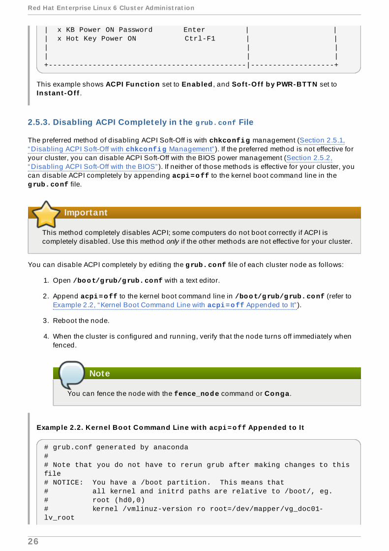
This example shows ACPI Funct ion set to Enabled , and Sof t -O f f by PWR-BTTN set toInstant -O f f .
2.5.3. Disabling ACPI Completely in the grub.conf File
The preferred method of disabling ACPI Soft-Off is with chkconfig management (Section 2.5.1,“Disabling ACPI Soft-Off with chkconfig Management” ). If the preferred method is not effective foryour cluster, you can disable ACPI Soft-Off with the BIOS power management (Section 2.5.2,“Disabling ACPI Soft-Off with the BIOS” ). If neither of those methods is effective for your cluster, youcan disable ACPI completely by appending acpi=off to the kernel boot command line in the grub.conf file.
Important
This method completely disables ACPI; some computers do not boot correctly if ACPI iscompletely disabled. Use this method only if the other methods are not effective for your cluster.
You can disable ACPI completely by editing the grub.conf file of each cluster node as follows:
1. Open /boot/grub/grub.conf with a text editor.
2. Append acpi=off to the kernel boot command line in /boot/grub/grub.conf (refer toExample 2.2, “Kernel Boot Command Line with acpi=off Appended to It” ).
3. Reboot the node.
4. When the cluster is configured and running, verify that the node turns off immediately whenfenced.
Note
You can fence the node with the fence_node command or Conga .
Example 2.2. Kernel Boot Command Line with acpi=off Appended to It
# grub.conf generated by anaconda## Note that you do not have to rerun grub after making changes to this file# NOTICE: You have a /boot partition. This means that# all kernel and initrd paths are relative to /boot/, eg.# root (hd0,0)# kernel /vmlinuz-version ro root=/dev/mapper/vg_doc01-lv_root
Red Hat Ent erprise Linux 6 Clust er Administ rat ion
26
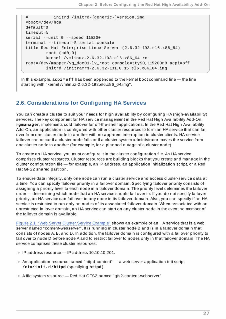
# initrd /initrd-[generic-]version.img#boot=/dev/hdadefault=0timeout=5serial --unit=0 --speed=115200terminal --timeout=5 serial consoletitle Red Hat Enterprise Linux Server (2.6.32-193.el6.x86_64) root (hd0,0) kernel /vmlinuz-2.6.32-193.el6.x86_64 ro root=/dev/mapper/vg_doc01-lv_root console=ttyS0,115200n8 acpi=off initrd /initramrs-2.6.32-131.0.15.el6.x86_64.img
In this example, acpi=off has been appended to the kernel boot command line — the linestarting with "kernel /vmlinuz-2.6.32-193.el6.x86_64.img".
2.6. Considerat ions for Configuring HA Services
You can create a cluster to suit your needs for high availability by configuring HA (high-availability)services. The key component for HA service management in the Red Hat High Availability Add-On, rgmanager, implements cold failover for off-the-shelf applications. In the Red Hat High AvailabilityAdd-On, an application is configured with other cluster resources to form an HA service that can failover from one cluster node to another with no apparent interruption to cluster clients. HA-servicefailover can occur if a cluster node fails or if a cluster system administrator moves the service fromone cluster node to another (for example, for a planned outage of a cluster node).
To create an HA service, you must configure it in the cluster configuration file. An HA servicecomprises cluster resources. Cluster resources are building blocks that you create and manage in thecluster configuration file — for example, an IP address, an application initialization script, or a RedHat GFS2 shared partition.
To ensure data integrity, only one node can run a cluster service and access cluster-service data ata time. You can specify failover priority in a failover domain. Specifying failover priority consists ofassigning a priority level to each node in a failover domain. The priority level determines the failoverorder — determining which node that an HA service should fail over to. If you do not specify failoverpriority, an HA service can fail over to any node in its failover domain. Also, you can specify if an HAservice is restricted to run only on nodes of its associated failover domain. When associated with anunrestricted failover domain, an HA service can start on any cluster node in the event no member ofthe failover domain is available.
Figure 2.1, “Web Server Cluster Service Example” shows an example of an HA service that is a webserver named "content-webserver" . It is running in cluster node B and is in a failover domain thatconsists of nodes A, B, and D. In addition, the failover domain is configured with a failover priority tofail over to node D before node A and to restrict failover to nodes only in that failover domain. The HAservice comprises these cluster resources:
IP address resource — IP address 10.10.10.201.
An application resource named "httpd-content" — a web server application init script /etc/init.d/httpd (specifying httpd ).
A file system resource — Red Hat GFS2 named "gfs2-content-webserver" .
Chapt er 2 . Before Configuring t he Red Hat High Availabilit y Add- On
27

Figure 2.1. Web Server Cluster Service Example
Clients access the HA service through the IP address 10.10.10.201, enabling interaction with the webserver application, httpd-content. The httpd-content application uses the gfs2-content-webserver filesystem. If node B were to fail, the content-webserver HA service would fail over to node D. If node Dwere not available or also failed, the service would fail over to node A. Failover would occur withminimal service interruption to the cluster clients. For example, in an HTTP service, certain stateinformation may be lost (like session data). The HA service would be accessible from another clusternode via the same IP address as it was before failover.
Note
For more information about HA services and failover domains, refer to the High Availability Add-On Overview. For information about configuring failover domains, refer to Chapter 3,Configuring Red Hat High Availability Add-On With Conga(using Conga) or Chapter 7, ConfiguringRed Hat High Availability Manually (using command line utilities).
An HA service is a group of cluster resources configured into a coherent entity that provides
Red Hat Ent erprise Linux 6 Clust er Administ rat ion
28

specialized services to clients. An HA service is represented as a resource tree in the clusterconfiguration file, /etc/cluster/cluster.conf (in each cluster node). In the clusterconfiguration file, each resource tree is an XML representation that specifies each resource, itsattributes, and its relationship among other resources in the resource tree (parent, child, and siblingrelationships).
Note
Because an HA service consists of resources organized into a hierarchical tree, a service issometimes referred to as a resource tree or resource group. Both phrases are synonymous withHA service.
At the root of each resource tree is a special type of resource — a service resource. Other types ofresources comprise the rest of a service, determining its characteristics. Configuring an HA serviceconsists of creating a service resource, creating subordinate cluster resources, and organizing theminto a coherent entity that conforms to hierarchical restrictions of the service.
There are two major considerations to take into account when configuring an HA service:
The types of resources needed to create a service
Parent, child, and sibling relationships among resources
The types of resources and the hierarchy of resources depend on the type of service you areconfiguring.
The types of cluster resources are listed in Appendix B, HA Resource Parameters. Information aboutparent, child, and sibling relationships among resources is described in Appendix C, HA ResourceBehavior.
2.7. Configurat ion Validat ion
The cluster configuration is automatically validated according to the cluster schema at /usr/share/cluster/cluster.rng during startup time and when a configuration is reloaded.Also, you can validate a cluster configuration any time by using the ccs_config_validatecommand. For information on configuration validation when using the ccs command, seeSection 5.1.6, “Configuration Validation” .
An annotated schema is available for viewing at /usr/share/doc/cman-X.Y.ZZ/cluster_conf.html (for example /usr/share/doc/cman-3.0.12/cluster_conf.html ).
Configuration validation checks for the following basic errors:
XML validity — Checks that the configuration file is a valid XML file.
Configuration options — Checks to make sure that options (XML elements and attributes) arevalid.
Option values — Checks that the options contain valid data (limited).
The following examples show a valid configuration and invalid configurations that illustrate thevalidation checks:
Valid configuration — Example 2.3, “cluster.conf Sample Configuration: Valid File”
Chapt er 2 . Before Configuring t he Red Hat High Availabilit y Add- On
29

Invalid XML — Example 2.4, “cluster.conf Sample Configuration: Invalid XML”
Invalid option — Example 2.5, “cluster.conf Sample Configuration: Invalid Option”
Invalid option value — Example 2.6, “cluster.conf Sample Configuration: Invalid OptionValue”
Example 2.3. cluster.conf Sample Conf igurat ion: Valid File
<cluster name="mycluster" config_version="1"> <logging debug="off"/> <clusternodes> <clusternode name="node-01.example.com" nodeid="1"> <fence> </fence> </clusternode> <clusternode name="node-02.example.com" nodeid="2"> <fence> </fence> </clusternode> <clusternode name="node-03.example.com" nodeid="3"> <fence> </fence> </clusternode> </clusternodes> <fencedevices> </fencedevices> <rm> </rm></cluster>
Example 2.4 . cluster.conf Sample Conf igurat ion: Invalid XML
<cluster name="mycluster" config_version="1"> <logging debug="off"/> <clusternodes> <clusternode name="node-01.example.com" nodeid="1"> <fence> </fence> </clusternode> <clusternode name="node-02.example.com" nodeid="2"> <fence> </fence> </clusternode> <clusternode name="node-03.example.com" nodeid="3"> <fence> </fence> </clusternode> </clusternodes> <fencedevices> </fencedevices>
Red Hat Ent erprise Linux 6 Clust er Administ rat ion
30

<rm> </rm><cluster> <----------------INVALID
In this example, the last line of the configuration (annotated as " INVALID" here) is missing a slash— it is <cluster> instead of </cluster>.
Example 2.5. cluster.conf Sample Conf igurat ion: Invalid Opt ion
<cluster name="mycluster" config_version="1"> <loging debug="off"/> <----------------INVALID <clusternodes> <clusternode name="node-01.example.com" nodeid="1"> <fence> </fence> </clusternode> <clusternode name="node-02.example.com" nodeid="2"> <fence> </fence> </clusternode> <clusternode name="node-03.example.com" nodeid="3"> <fence> </fence> </clusternode> </clusternodes> <fencedevices> </fencedevices> <rm> </rm><cluster>
In this example, the second line of the configuration (annotated as " INVALID" here) contains aninvalid XML element — it is loging instead of logging .
Example 2.6 . cluster.conf Sample Conf igurat ion: Invalid Opt ion Value
<cluster name="mycluster" config_version="1"> <loging debug="off"/> <clusternodes> <clusternode name="node-01.example.com" nodeid="-1"> <--------INVALID <fence> </fence> </clusternode> <clusternode name="node-02.example.com" nodeid="2"> <fence> </fence> </clusternode> <clusternode name="node-03.example.com" nodeid="3">
Chapt er 2 . Before Configuring t he Red Hat High Availabilit y Add- On
31

<fence> </fence> </clusternode> </clusternodes> <fencedevices> </fencedevices> <rm> </rm><cluster>
In this example, the fourth line of the configuration (annotated as " INVALID" here) contains aninvalid value for the XML attribute, nodeid in the clusternode line for node-01.example.com. The value is a negative value ("-1") instead of a positive value ("1"). For the nodeid attribute, the value must be a positive value.
2.8. Considerat ions for NetworkManager
The use of NetworkManager is not supported on cluster nodes. If you have installedNetworkManager on your cluster nodes, you should either remove it or disable it.
Note
The cman service will not start if NetworkManager is either running or has been configured torun with the chkconfig command.
2.9. Considerat ions for Using Quorum Disk
Quorum Disk is a disk-based quorum daemon, qdiskd , that provides supplemental heuristics todetermine node fitness. With heuristics you can determine factors that are important to the operationof the node in the event of a network partition. For example, in a four-node cluster with a 3:1 split,ordinarily, the three nodes automatically "win" because of the three-to-one majority. Under thosecircumstances, the one node is fenced. With qdiskd however, you can set up heuristics that allowthe one node to win based on access to a critical resource (for example, a critical network path). Ifyour cluster requires additional methods of determining node health, then you should configure qdiskd to meet those needs.
Note
Configuring qdiskd is not required unless you have special requirements for node health. Anexample of a special requirement is an "all-but-one" configuration. In an all-but-oneconfiguration, qdiskd is configured to provide enough quorum votes to maintain quorumeven though only one node is working.
Red Hat Ent erprise Linux 6 Clust er Administ rat ion
32

Important
Overall, heuristics and other qdiskd parameters for your deployment depend on the siteenvironment and special requirements needed. To understand the use of heuristics and other qdiskd parameters, refer to the qdisk(5) man page. If you require assistance understandingand using qdiskd for your site, contact an authorized Red Hat support representative.
If you need to use qdiskd , you should take into account the following considerations:
Cluster node votes
When using Quorum Disk, each cluster node must have one vote.
CMAN membership t imeout value
The qdiskd membership timeout value is automatically configured based on the CMANmembership timeout value (the time a node needs to be unresponsive before CMANconsiders that node to be dead, and not a member). qdiskd also performs extra sanitychecks to guarantee that it can operate within the CMAN timeout. If you find that you need toreset this value, you must take the following into account:
The CMAN membership timeout value should be at least two times that of the qdiskdmembership timeout value. The reason is because the quorum daemon must detect failednodes on its own, and can take much longer to do so than CMAN. Other site-specificconditions may affect the relationship between the membership timeout values of CMAN andqdiskd . For assistance with adjusting the CMAN membership timeout value, contact anauthorized Red Hat support representative.
Fencing
To ensure reliable fencing when using qdiskd , use power fencing. While other types offencing can be reliable for clusters not configured with qdiskd , they are not reliable for acluster configured with qdiskd .
Maximum nodes
A cluster configured with qdiskd supports a maximum of 16 nodes. The reason for thelimit is because of scalability; increasing the node count increases the amount ofsynchronous I/O contention on the shared quorum disk device.
Quorum disk device
A quorum disk device should be a shared block device with concurrent read/write accessby all nodes in a cluster. The minimum size of the block device is 10 Megabytes. Examplesof shared block devices that can be used by qdiskd are a multi-port SCSI RAID array, aFibre Channel RAID SAN, or a RAID-configured iSCSI target. You can create a quorum diskdevice with mkqdisk, the Cluster Quorum Disk Utility. For information about using theutility refer to the mkqdisk(8) man page.
Chapt er 2 . Before Configuring t he Red Hat High Availabilit y Add- On
33

Note
Using JBOD as a quorum disk is not recommended. A JBOD cannot providedependable performance and therefore may not allow a node to write to it quicklyenough. If a node is unable to write to a quorum disk device quickly enough, thenode is falsely evicted from a cluster.
2.10. Red Hat High Availabilit y Add-On and SELinux
The High Availability Add-On for Red Hat Enterprise Linux 6 supports SELinux in the enforcingstate with the SELinux policy type set to targeted .
Note
When using SELinux with the High Availability Add-On in a VM environment, you shouldensure that the SELinux boolean fenced_can_network_connect is persistently set to on.This allows the fence_xvm fencing agent to work properly, enabling the system to fencevirtual machines.
For more information about SELinux, refer to Deployment Guide for Red Hat Enterprise Linux 6.
2.11. Mult icast Addresses
The nodes in a cluster communicate among each other using multicast addresses. Therefore, eachnetwork switch and associated networking equipment in the Red Hat High Availability Add-On mustbe configured to enable multicast addresses and support IGMP (Internet Group ManagementProtocol). Ensure that each network switch and associated networking equipment in the Red HatHigh Availability Add-On are capable of supporting multicast addresses and IGMP; if they are,ensure that multicast addressing and IGMP are enabled. Without multicast and IGMP, not all nodescan participate in a cluster, causing the cluster to fail; use UDP unicast in these environments, asdescribed in Section 2.12, “UDP Unicast Traffic” .
Note
Procedures for configuring network switches and associated networking equipment varyaccording each product. Refer to the appropriate vendor documentation or other informationabout configuring network switches and associated networking equipment to enable multicastaddresses and IGMP.
2.12. UDP Unicast Traffic
As of the Red Hat Enterprise Linux 6.2 release, the nodes in a cluster can communicate with eachother using the UDP Unicast transport mechanism. It is recommended, however, that you use IPmulticasting for the cluster network. UDP unicast is an alternative that can be used when IPmulticasting is not available.
Red Hat Ent erprise Linux 6 Clust er Administ rat ion
34

You can configure the Red Hat High-Availability Add-On to use UDP unicast by setting the cman transport="udpu" parameter in the cluster.conf configuration file. You can also specifyUnicast from the Network Conf igurat ion page of the Conga user interface, as described inSection 3.5.3, “Network Configuration” .
2.13. Considerat ions for ricci
For Red Hat Enterprise Linux 6, ricci replaces ccsd . Therefore, it is necessary that ricci isrunning in each cluster node to be able to propagate updated cluster configuration whether it is viathe cman_tool version -r command, the ccs command, or the luci user interface server. Youcan start ricci by using service ricci start or by enabling it to start at boot time via chkconfig . For information on enabling IP ports for ricci , refer to Section 2.3.1, “Enabling IPPorts on Cluster Nodes” .
For the Red Hat Enterprise Linux 6.1 release and later, using ricci requires a password the first timeyou propagate updated cluster configuration from any particular node. You set the ricci passwordas root after you install ricci on your system. To set this password, execute the passwd riccicommand, for user ricci .
2.14. Configuring Virtual Machines in a Clustered Environment
When you configure your cluster with virtual machine resources, you should use the rgmanagertools to start and stop the virtual machines. Using virsh to start the machine can result in the virtualmachine running in more than one place, which can cause data corruption in the virtual machine.
To reduce the chances of administrators accidentally "double-starting" virtual machines by usingboth cluster and non-cluster tools in a clustered environment, you can configure your system bystoring the virtual machine configuration files in a non-default location. Storing the virtual machineconfiguration files somewhere other than their default location makes it more difficult to accidentallystart a virtual machine using virsh, as the configuration file will be unknown out of the box to virsh.
The non-default location for virtual machine configuration files may be anywhere. The advantage ofusing an NFS share or a shared GFS2 file system is that the administrator does not need to keep theconfiguration files in sync across the cluster members. However, it is also permissible to use a localdirectory as long as the administrator keeps the contents synchronized somehow cluster-wide.
In the cluster configuration, virtual machines may reference this non-default location by using the path attribute of a virtual machine resource. Note that the path attribute is a directory or set ofdirectories separated by the colon ':' character, not a path to a specific file.
Warning
The libvirt-guests service should be disabled on all the nodes that are running rgmanager. If a virtual machine autostarts or resumes, this can result in the virtual machinerunning in more than one place, which can cause data corruption in the virtual machine.
For more information on the attributes of a virtual machine resources, refer to Table B.26, “VirtualMachine (vm Resource)” .
Chapt er 2 . Before Configuring t he Red Hat High Availabilit y Add- On
35

Chapter 3. Configuring Red Hat High Availability Add-On WithConga
This chapter describes how to configure Red Hat High Availability Add-On software using Conga .For information on using Conga to manage a running cluster, see Chapter 4, Managing Red Hat HighAvailability Add-On With Conga.
Note
Conga is a graphical user interface that you can use to administer the Red Hat HighAvailability Add-On. Note, however, that in order to use this interface effectively you need tohave a good and clear understanding of the underlying concepts. Learning about clusterconfiguration by exploring the available features in the user interface is not recommended, asit may result in a system that is not robust enough to keep all services running whencomponents fail.
This chapter consists of the following sections:
Section 3.1, “Configuration Tasks”
Section 3.2, “Starting luci”
Section 3.3, “Controlling Access to luci”
Section 3.4, “Creating a Cluster”
Section 3.5, “Global Cluster Properties”
Section 3.6, “Configuring Fence Devices”
Section 3.7, “Configuring Fencing for Cluster Members”
Section 3.8, “Configuring a Failover Domain”
Section 3.9, “Configuring Global Cluster Resources”
Section 3.10, “Adding a Cluster Service to the Cluster”
3.1. Configurat ion Tasks
Configuring Red Hat High Availability Add-On software with Conga consists of the following steps:
1. Configuring and running the Conga configuration user interface — the luci server. Refer toSection 3.2, “Starting luci” .
2. Creating a cluster. Refer to Section 3.4, “Creating a Cluster” .
3. Configuring global cluster properties. Refer to Section 3.5, “Global Cluster Properties” .
4. Configuring fence devices. Refer to Section 3.6, “Configuring Fence Devices” .
5. Configuring fencing for cluster members. Refer to Section 3.7, “Configuring Fencing forCluster Members” .
6. Creating failover domains. Refer to Section 3.8, “Configuring a Failover Domain” .
Red Hat Ent erprise Linux 6 Clust er Administ rat ion
36

7. Creating resources. Refer to Section 3.9, “Configuring Global Cluster Resources” .
8. Creating cluster services. Refer to Section 3.10, “Adding a Cluster Service to the Cluster” .
3.2. Start ing luci
Installing ricci
Using luci to configure a cluster requires that ricci be installed and running on the clusternodes, as described in Section 2.13, “Considerations for ricci ” . As noted in that section,using ricci requires a password which luci requires you to enter for each cluster nodewhen you create a cluster, as described in Section 3.4, “Creating a Cluster” .
Before starting luci , ensure that the IP ports on your cluster nodes allow connections to port11111 from the luci server on any nodes that luci will be communicating with. For informationon enabling IP ports on cluster nodes, see Section 2.3.1, “Enabling IP Ports on ClusterNodes” .
To administer Red Hat High Availability Add-On with Conga , install and run luci as follows:
1. Select a computer to host luci and install the luci software on that computer. For example:
# yum install luci
Note
Typically, a computer in a server cage or a data center hosts luci ; however, a clustercomputer can host luci .
2. Start luci using service luci start. For example:
# service luci startStarting luci: generating https SSL certificates... done [ OK ]
Please, point your web browser to https://nano-01:8084 to access luci
Note
As of Red Hat Enterprise Linux release 6.1, you can configure some aspects of luci 'sbehavior by means of the /etc/sysconfig/luci file, including the port and hostparameters, as described in Section 2.4, “Configuring luci with /etc/sysconfig/luci ” . Modified port and host parameters will automatically bereflected in the URL displayed when the luci service starts.
3. At a Web browser, place the URL of the luci server into the URL address box and click Go (orthe equivalent). The URL syntax for the luci server is
Chapt er 3. Configuring Red Hat High Availabilit y Add- On Wit h Conga
37

https://luci_server_hostname:luci_server_port. The default value ofluci_server_port is 8084 .
The first time you access luci , a web browser specific prompt regarding the self-signed SSLcertificate (of the luci server) is displayed. Upon acknowledging the dialog box or boxes,your Web browser displays the luci login page.
4. Any user able to authenticate on the system that is hosting luci can log in to luci . As of RedHat Enterprise Linux 6.2 only the root user on the system that is running luci can access anyof the luci components until an administrator (the root user or a user with administratorpermission) sets permissions for that user. For information on setting luci permissions forusers, refer to Section 3.3, “Controlling Access to luci” .
Logging in to luci displays the luci Homebase page, as shown in Figure 3.1, “ luciHomebase page” .
Figure 3.1. luci Homebase page
Note
There is an idle timeout for luci that logs you out after 15 minutes of inactivity.
3.3. Cont rolling Access to luci
Since the initial release of Red Hat Enterprise Linux 6, the following features have been added to theUsers and Permisions page.
As of Red Hat Enterprise Linux 6.2, the root user or a user who has been granted luciadministrator permissions on a system running luci can control access to the various lucicomponents by setting permissions for the individual users on a system.
As of Red Hat Enterprise Linux 6.3, the root user or a user who has been granted luciadministrator permissions can add users to the luci interface and then set the user permissionsfor that user. You will still need to add that user to the system and set up a password for that user,but this feature allows you to configure permissions for the user before the user has logged in to
Red Hat Ent erprise Linux 6 Clust er Administ rat ion
38

luci for the first time.
As of Red Hat Enterprise Linux 6.4, the root user or a user who has been granted luciadministrator permissions can also use the luci interface to delete users from the luci interface,which resets any permissions you have configured for that user.
Note
You can modify the way in which luci performs authentication by editing the /etc/pam.d/luci file on the system. For information on using Linux-PAM, see the pam(8)man page.
To add users, delete users, or set the user permissions, log in to luci as root or as a user who haspreviously been granted administrator permissions and click the Admin selection in the upper rightcorner of the luci screen. This brings up the Users and Permissions page, which displays theexisting users.
To add a user to the luci interface, click on Add a User and enter the name of the user to add. Youcan then set permissions for that user, although you will still need to set up a password for that user.
To delete users from the luci interface, resetting any permissions you have configured for that user,select the user or users and click on Delete Selected .
To set or change permissions for a user, select the user from the dropdown menu under UserPermissions . This allows you to set the following permissions:
Luci Administrator
Grants the user the same permissions as the root user, with full permissions on all clustersand the ability to set or remove permissions on all other users except root, whosepermissions cannot be restricted.
Can Create Clusters
Allows the user to create new clusters, as described in Section 3.4, “Creating a Cluster” .
Can Import Existing Clusters
Allows the user to add an existing cluster to the luci interface, as described in Section 4.1,“Adding an Existing Cluster to the luci Interface” .
For each cluster that has been created or imported to luci , you can set the following permissions forthe indicated user:
Can View This Cluster
Allows the user to view the specified cluster.
Can Change the Cluster Configuration
Allows the user to modify the configuration for the specified cluster, with the exception ofadding and removing cluster nodes.
Can Enable, Disable, Relocate, and Migrate Service Groups
Allows the user to manage high-availability services, as described in Section 4.5,“Managing High-Availability Services” .
Chapt er 3. Configuring Red Hat High Availabilit y Add- On Wit h Conga
39

Can Stop, Start, and Reboot Cluster Nodes
Allows the user to manage the individual nodes of a cluster, as described in Section 4.3,“Managing Cluster Nodes” .
Can Add and Delete Nodes
Allows the user to add and delete nodes from a cluster, as described in Section 3.4,“Creating a Cluster” .
Can Remove This Cluster from Luci
Allows the user to remove a cluster from the luci interface, as described in Section 4.4,“Starting, Stopping, Restarting, and Deleting Clusters” .
Click Submit for the permissions to take affect, or click Reset to return to the initial values.
3.4 . Creat ing a Cluster
Creating a cluster with luci consists of naming a cluster, adding cluster nodes to the cluster, enteringthe ricci passwords for each node, and submitting the request to create a cluster. If the nodeinformation and passwords are correct, Conga automatically installs software into the cluster nodes(if the appropriate software packages are not currently installed) and starts the cluster. Create acluster as follows:
1. Click Manage Clusters from the menu on the left side of the luci Homebase page. TheClusters screen appears, as shown in Figure 3.2, “ luci cluster management page” .
Figure 3.2. luci cluster management page
2. Click Create . The Create New Cluster dialog box appears, as shown in Figure 3.3, “ lucicluster creation dialog box” .
Red Hat Ent erprise Linux 6 Clust er Administ rat ion
4 0

Figure 3.3. luci cluster creat ion d ialog box
3. Enter the following parameters on the Create New Cluster dialog box, as necessary:
At the Cluster Name text box, enter a cluster name. The cluster name cannot exceed 15characters.
If each node in the cluster has the same ricci password, you can check Use the samepassword for all nodes to autofill the password field as you add nodes.
Enter the node name for a node in the cluster in the Node Name column and enter thericci password for the node in the Password column. A node name can be up to 255bytes in length.
If your system is configured with a dedicated private network that is used only for clustertraffic, you may want to configure luci to communicate with ricci on an address that isdifferent from the address to which the cluster node name resolves. You can do this byentering that address as the Ricci Hostname .
If you are using a different port for the ricci agent than the default of 11111, you canchange that parameter.
Click Add Another Node and enter the node name and ricci password for eachadditional node in the cluster.
If you do not want to upgrade the cluster software packages that are already installed onthe nodes when you create the cluster, leave the Use locally installed packagesoption selected. If you want to upgrade all cluster software packages, select theDownload Packages option.
Chapt er 3. Configuring Red Hat High Availabilit y Add- On Wit h Conga
4 1

Note
Whether you select the Use locally installed packages or the DownloadPackages option, if any of the base cluster components are missing (cman, rgmanager, modcluster and all their dependencies), they will be installed. If theycannot be installed, the node creation will fail.
Check Reboot nodes before jo in ing cluster if desired.
Select Enable shared storage support if clustered storage is required; this downloadsthe packages that support clustered storage and enables clustered LVM. You shouldselect this only when you have access to the Resilient Storage Add-On or the ScalableFile System Add-On.
4. Click Create Cluster. Clicking Create Cluster causes the following actions:
a. If you have selected Download Packages , the cluster software packages aredownloaded onto the nodes.
b. Cluster software is installed onto the nodes (or it is verified that the appropriatesoftware packages are installed).
c. The cluster configuration file is updated and propagated to each node in the cluster.
d. The added nodes join the cluster.
A message is displayed indicating that the cluster is being created. When the cluster is ready,the display shows the status of the newly created cluster, as shown in Figure 3.4, “Clusternode display” . Note that if ricci is not running on any of the nodes, the cluster creation willfail.
Figure 3.4 . Cluster node d isplay
5. After clicking Create Cluster, you can add or delete nodes from the cluster by clicking theAdd or Delete function from the menu at the top of the cluster node display page. Unlessyou are deleting an entire cluster, nodes must be stopped before being deleted. For
Red Hat Ent erprise Linux 6 Clust er Administ rat ion
4 2

information on deleting a node from an existing cluster that is currently in operation, seeSection 4.3.4, “Deleting a Member from a Cluster” .
Warning
Removing a cluster node from the cluster is a destructive operation that cannot beundone.
3.5. Global Cluster Propert ies
When you select a cluster to configure, a cluster-specific page is displayed. The page provides aninterface for configuring cluster-wide properties. You can configure cluster-wide properties byclicking on Conf igure along the top of the cluster display. This yields a tabbed interface whichprovides the following tabs: General , Fence Daemon , Network , Redundant Ring , QDisk andLogging . To configure the parameters in those tabs, follow the steps in the following sections. If youdo not need to configure parameters in a tab, skip the section for that tab.
3.5.1. Configuring General Propert ies
Clicking on the General tab displays the General Propert ies page, which provides an interfacefor modifying the configuration version.
The Cluster Name text box displays the cluster name; it does not accept a cluster name change.The only way to change the name of a cluster is to create a new cluster configuration with the newname.
The Conf igurat ion Version value is set to 1 at the time of cluster creation and is automaticallyincremented each time you modify your cluster configuration. However, if you need to set it toanother value, you can specify it at the Conf igurat ion Version text box.
If you have changed the Conf igurat ion Version value, click Apply for this change to take effect.
3.5.2. Configuring Fence Daemon Propert ies
Clicking on the Fence Daemon tab displays the Fence Daemon Propert ies page, which providesan interface for configuring Post Fail Delay and Post Join Delay. The values you configure forthese parameters are general fencing properties for the cluster. To configure specific fence devicesfor the nodes of the cluster, use the Fence Devices menu item of the cluster display, as described inSection 3.6, “Configuring Fence Devices” .
The Post Fail Delay parameter is the number of seconds the fence daemon (fenced ) waitsbefore fencing a node (a member of the fence domain) after the node has failed. The Post FailDelay default value is 0 . Its value may be varied to suit cluster and network performance.
The Post Join Delay parameter is the number of seconds the fence daemon (fenced ) waitsbefore fencing a node after the node joins the fence domain. luci sets the Post Join Delay valueto 6 . A typical setting for Post Join Delay is between 20 and 30 seconds, but can varyaccording to cluster and network performance.
Enter the values required and click Apply for changes to take effect.
Chapt er 3. Configuring Red Hat High Availabilit y Add- On Wit h Conga
4 3

Note
For more information about Post Join Delay and Post Fail Delay, refer to the fenced(8)man page.
3.5.3. Network Configurat ion
Clicking on the Network tab displays the Network Conf igurat ion page, which provides aninterface for configuring the network transport type.
You can use this tab to select one of the following options:
UDP Mult icast and Let Cluster Choose the Mult icast Address
This is the default setting. With this option selected, the Red Hat High Availability Add-On softwarecreates a multicast address based on the cluster ID. It generates the lower 16 bits of the addressand appends them to the upper portion of the address according to whether the IP protocol isIPv4 or IPv6:
For IPv4 — The address formed is 239.192. plus the lower 16 bits generated by Red Hat HighAvailability Add-On software.
For IPv6 — The address formed is FF15:: plus the lower 16 bits generated by Red Hat HighAvailability Add-On software.
Note
The cluster ID is a unique identifier that cman generates for each cluster. To view the clusterID, run the cman_tool status command on a cluster node.
UDP Mult icast and Specify the Mult icast Address Manually
If you need to use a specific multicast address, select this option enter a multicast address into theMult icast Address text box.
If you do specify a multicast address, you should use the 239.192.x.x series (or FF15:: for IPv6)that cman uses. Otherwise, using a multicast address outside that range may cause unpredictableresults. For example, using 224.0.0.x (which is "All hosts on the network") may not be routedcorrectly, or even routed at all by some hardware.
If you specify or modify a multicast address, you must restart the cluster for this to take effect. Forinformation on starting and stopping a cluster with Conga , refer to Section 4.4, “Starting,Stopping, Restarting, and Deleting Clusters” .
Note
If you specify a multicast address, make sure that you check the configuration of routersthat cluster packets pass through. Some routers may take a long time to learn addresses,seriously impacting cluster performance.
UDP Unicast (UDPU)
Red Hat Ent erprise Linux 6 Clust er Administ rat ion
4 4

As of the Red Hat Enterprise Linux 6.2 release, the nodes in a cluster can communicate with eachother using the UDP Unicast transport mechanism. It is recommended, however, that you use IPmulticasting for the cluster network. UDP Unicast is an alternative that can be used when IPmulticasting is not available. For GFS2 deployments using UDP Unicast is not recommended.
Click Apply. When changing the transport type, a cluster restart is necessary for the changes to takeeffect.
3.5.4 . Configuring Redundant Ring Protocol
As of Red Hat Enterprise Linux 6.4, the Red Hat High Availability Add-On supports the configurationof redundant ring protocol. When using redundant ring protocol, there are a variety ofconsiderations you must take into account, as described in Section 7.6, “Configuring RedundantRing Protocol” .
Clicking on the Redundant Ring tab displays the Redundant Ring Protocol Conf igurat ionpage. This page displays all of the nodes that are currently configured for the cluster. If you areconfiguring a system to use redundant ring protocol, you must specify the Alternate Name for eachnode for the second ring.
The Redundant Ring Protocol Conf igurat ion page optionally allows you to specify theAlternate Ring Mult icast Address , the Alternate Ring CMAN Port , and the Alternate RingMult icast Packet TTL for the second ring.
If you specify a multicast address for the second ring, either the alternate multicast address or thealternate port must be different from the multicast address for the first ring. If you specify an alternateport, the port numbers of the first ring and the second ring must differ by at least two, since the systemitself uses port and port-1 to perform operations. If you do not specify an alternate multicast address,the system will automatically use a different multicast address for the second ring.
3.5.5. Quorum Disk Configurat ion
Clicking on the QDisk tab displays the Quorum Disk Conf igurat ion page, which provides aninterface for configuring quorum disk parameters if you need to use a quorum disk.
Important
Quorum disk parameters and heuristics depend on the site environment and the specialrequirements needed. To understand the use of quorum disk parameters and heuristics, referto the qdisk(5) man page. If you require assistance understanding and using quorum disk,contact an authorized Red Hat support representative.
The Do Not Use a Quorum Disk parameter is enabled by default. If you need to use a quorumdisk, click Use a Quorum Disk , enter the quorum disk parameters, and click Apply. You mustrestart the cluster for the changes to take effect.
Table 3.1, “Quorum-Disk Parameters” describes the quorum disk parameters.
Table 3.1. Quorum-Disk Parameters
Parameter Descript ion
Chapt er 3. Configuring Red Hat High Availabilit y Add- On Wit h Conga
4 5

Specify PhysicalDevice: By DeviceLabel
Specifies the quorum disk label created by the mkqdisk utility. If this fieldis used, the quorum daemon reads the /proc/partitions file andchecks for qdisk signatures on every block device found, comparing thelabel against the specified label. This is useful in configurations wherethe quorum device name differs among nodes.
Heurist ics Path to Program — The program used to determine if this heuristic isavailable. This can be anything that can be executed by /bin/sh -c. Areturn value of 0 indicates success; anything else indicates failure. Thisfield is required.
In terval — The frequency (in seconds) at which the heuristic is polled.The default interval for every heuristic is 2 seconds.
Score — The weight of this heuristic. The default score for each heuristicis 1.
TKO — The number of consecutive failures required before this heuristicis declared unavailable.
Minimum TotalScore
The minimum score for a node to be considered "alive". If omitted or set to0, the default function, floor((n+1)/2), is used, where n is the sum ofthe heuristics scores. The Minimum Total Score value must neverexceed the sum of the heuristic scores; otherwise, the quorum disk cannotbe available.
Parameter Descript ion
Note
Clicking Apply on the QDisk Conf igurat ion tab propagates changes to the clusterconfiguration file (/etc/cluster/cluster.conf) in each cluster node. However, for thequorum disk to operate or for any modifications you have made to the quorum diskparameters to take effect, you must restart the cluster (refer to Section 4.4, “Starting, Stopping,Restarting, and Deleting Clusters” ), ensuring that you have restarted the qdiskd daemon oneach node.
3.5.6. Logging Configurat ion
Clicking on the Logging tab displays the Logging Conf igurat ion page, which provides aninterface for configuring logging settings.
You can configure the following settings for global logging configuration:
Checking Log Debugging Messages enables debugging messages in the log file.
Checking Log Messages to Syslog enables messages to syslog . You can select the SyslogMessage Facility and the Syslog Message Priority. The Syslog Message Priority settingindicates that messages at the selected level and higher are sent to syslog .
Checking Log Messages to Log File enables messages to the log file. You can specify the LogFile Path name. The logf ile message priority setting indicates that messages at the selectedlevel and higher are written to the log file.
You can override the global logging settings for specific daemons by selecting one of the daemonslisted beneath the Daemon-specif ic Logging Overrides heading at the bottom of the Logging
Red Hat Ent erprise Linux 6 Clust er Administ rat ion
4 6

Conf igurat ion page. After selecting the daemon, you can check whether to log the debuggingmessages for that particular daemon. You can also specify the syslog and log file settings for thatdaemon.
Click Apply for the logging configuration changes you have specified to take effect.
3.6. Configuring Fence Devices
Configuring fence devices consists of creating, updating, and deleting fence devices for the cluster.You must configure the fence devices in a cluster before you can configure fencing for the nodes inthe cluster.
Creating a fence device consists of selecting a fence device type and entering parameters for thatfence device (for example, name, IP address, login, and password). Updating a fence device consistsof selecting an existing fence device and changing parameters for that fence device. Deleting a fencedevice consists of selecting an existing fence device and deleting it.
Note
It is recommended that you configure multiple fencing mechanisms for each node. A fencingdevice can fail due to network split, a power outage, or a problem in the fencing device itself.Configuring multiple fencing mechanisms can reduce the likelihood that the failure of afencing device will have fatal results.
This section provides procedures for the following tasks:
Creating fence devices — Refer to Section 3.6.1, “Creating a Fence Device” . Once you havecreated and named a fence device, you can configure the fence devices for each node in thecluster, as described in Section 3.7, “Configuring Fencing for Cluster Members” .
Updating fence devices — Refer to Section 3.6.2, “Modifying a Fence Device” .
Deleting fence devices — Refer to Section 3.6.3, “Deleting a Fence Device” .
From the cluster-specific page, you can configure fence devices for that cluster by clicking on FenceDevices along the top of the cluster display. This displays the fence devices for the cluster anddisplays the menu items for fence device configuration: Add and Delete . This is the starting point ofeach procedure described in the following sections.
Note
If this is an initial cluster configuration, no fence devices have been created, and thereforenone are displayed.
Figure 3.5, “ luci fence devices configuration page” shows the fence devices configuration screenbefore any fence devices have been created.
Chapt er 3. Configuring Red Hat High Availabilit y Add- On Wit h Conga
4 7

Figure 3.5. luci fence devices conf igurat ion page
3.6.1. Creat ing a Fence Device
To create a fence device, follow these steps:
1. From the Fence Devices configuration page, click Add . Clicking Add displays the Add Fence Device (Instance) dialog box. From this dialog box, select the type of fencedevice to configure.
2. Specify the information in the Add Fence Device (Instance) dialog box according tothe type of fence device. Refer to Appendix A, Fence Device Parameters for more informationabout fence device parameters. In some cases you will need to specify additional node-specific parameters for the fence device when you configure fencing for the individual nodes,as described in Section 3.7, “Configuring Fencing for Cluster Members” .
3. Click Submit.
After the fence device has been added, it appears on the Fence Devices configuration page.
3.6.2. Modifying a Fence Device
To modify a fence device, follow these steps:
1. From the Fence Devices configuration page, click on the name of the fence device to modify.This displays the dialog box for that fence device, with the values that have been configuredfor the device.
2. To modify the fence device, enter changes to the parameters displayed. Refer to Appendix A,Fence Device Parameters for more information.
3. Click Apply and wait for the configuration to be updated.
3.6.3. Delet ing a Fence Device
Red Hat Ent erprise Linux 6 Clust er Administ rat ion
4 8

Note
Fence devices that are in use cannot be deleted. To delete a fence device that a node iscurrently using, first update the node fence configuration for any node using the device andthen delete the device.
To delete a fence device, follow these steps:
1. From the Fence Devices configuration page, check the box to the left of the fence device ordevices to select the devices to delete.
2. Click Delete and wait for the configuration to be updated. A message appears indicatingwhich devices are being deleted.
When the configuration has been updated, the deleted fence device no longer appears in the display.
3.7. Configuring Fencing for Cluster Members
Once you have completed the initial steps of creating a cluster and creating fence devices, you needto configure fencing for the cluster nodes by following the steps in this section. Note that you mustconfigure fencing for each node in the cluster.
The following sections provide procedures for configuring a single fence device for a node,configuring a node with a backup fence device, and configuring a node with redundant powersupplies:
Section 3.7.1, “Configuring a Single Fence Device for a Node”
Section 3.7.2, “Configuring a Backup Fence Device”
Section 3.7.3, “Configuring a Node with Redundant Power”
3.7.1. Configuring a Single Fence Device for a Node
Use the following procedure to configure a node with a single fence device.
1. From the cluster-specific page, you can configure fencing for the nodes in the cluster byclicking on Nodes along the top of the cluster display. This displays the nodes thatconstitute the cluster. This is also the default page that appears when you click on the clustername beneath Manage Clusters from the menu on the left side of the luci Homebasepage.
2. Click on a node name. Clicking a link for a node causes a page to be displayed for that linkshowing how that node is configured.
The node-specific page displays any services that are currently running on the node, as wellas any failover domains of which this node is a member. You can modify an existing failoverdomain by clicking on its name. For information on configuring failover domains, seeSection 3.8, “Configuring a Failover Domain” .
3. On the node-specific page, under Fence Devices , click Add Fence Method . This displaysthe Add Fence Method to Node dialog box.
Chapt er 3. Configuring Red Hat High Availabilit y Add- On Wit h Conga
4 9

4. Enter a Method Name for the fencing method that you are configuring for this node. This isan arbitrary name that will be used by Red Hat High Availability Add-On; it is not the same asthe DNS name for the device.
5. Click Submit. This displays the node-specific screen that now displays the method you havejust added under Fence Devices .
6. Configure a fence instance for this method by clicking the Add Fence Instance button thatappears beneath the fence method. This displays the Add Fence Device ( Instance) drop-down menu from which you can select a fence device you have previously configured, asdescribed in Section 3.6.1, “Creating a Fence Device” .
7. Select a fence device for this method. If this fence device requires that you configure node-specific parameters, the display shows the parameters to configure. For information onfencing parameters, refer to Appendix A, Fence Device Parameters.
Note
For non-power fence methods (that is, SAN/storage fencing), Unfencing is selectedby default on the node-specific parameters display. This ensures that a fenced node'saccess to storage is not re-enabled until the node has been rebooted. When youconfigure a device that requires unfencing, the cluster must first be stopped and the fullconfiguration including devices and unfencing must be added before the cluster isstarted. For information on unfencing a node, refer to the fence_node(8) man page.
8. Click Submit. This returns you to the node-specific screen with the fence method and fenceinstance displayed.
3.7.2. Configuring a Backup Fence Device
You can define multiple fencing methods for a node. If fencing fails using the first method, the systemwill attempt to fence the node using the second method, followed by any additional methods youhave configured.
Use the following procedure to configure a backup fence device for a node.
1. Use the procedure provided in Section 3.7.1, “Configuring a Single Fence Device for a Node”to configure the primary fencing method for a node.
2. Beneath the display of the primary method you defined, click Add Fence Method .
3. Enter a name for the backup fencing method that you are configuring for this node and click Submit. This displays the node-specific screen that now displays the method you have justadded, below the primary fence method.
4. Configure a fence instance for this method by clicking Add Fence Instance. This displaysa drop-down menu from which you can select a fence device you have previously configured,as described in Section 3.6.1, “Creating a Fence Device” .
5. Select a fence device for this method. If this fence device requires that you configure node-specific parameters, the display shows the parameters to configure. For information onfencing parameters, refer to Appendix A, Fence Device Parameters.
6. Click Submit. This returns you to the node-specific screen with the fence method and fenceinstance displayed.
Red Hat Ent erprise Linux 6 Clust er Administ rat ion
50

You can continue to add fencing methods as needed. You can rearrange the order of fencingmethods that will be used for this node by clicking on Move Up and Move Down .
3.7.3. Configuring a Node with Redundant Power
If your cluster is configured with redundant power supplies for your nodes, you must be sure toconfigure fencing so that your nodes fully shut down when they need to be fenced. If you configureeach power supply as a separate fence method, each power supply will be fenced separately; thesecond power supply will allow the system to continue running when the first power supply is fencedand the system will not be fenced at all. To configure a system with dual power supplies, you mustconfigure your fence devices so that both power supplies are shut off and the system is takencompletely down. When configuring your system using Conga , this requires that you configure twoinstances within a single fencing method.
To configure fencing for a node with dual power supplies, follow the steps in this section.
1. Before you can configure fencing for a node with redundant power, you must configure eachof the power switches as a fence device for the cluster. For information on configuring fencedevices, see Section 3.6, “Configuring Fence Devices” .
2. From the cluster-specific page, click on Nodes along the top of the cluster display. Thisdisplays the nodes that constitute the cluster. This is also the default page that appears whenyou click on the cluster name beneath Manage Clusters from the menu on the left side ofthe luci Homebase page.
3. Click on a node name. Clicking a link for a node causes a page to be displayed for that linkshowing how that node is configured.
4. On the node-specific page, click Add Fence Method .
5. Enter a name for the fencing method that you are configuring for this node.
6. Click Submit. This displays the node-specific screen that now displays the method you havejust added under Fence Devices .
7. Configure the first power supply as a fence instance for this method by clicking Add Fence Instance. This displays a drop-down menu from which you can select one of the powerfencing devices you have previously configured, as described in Section 3.6.1, “Creating aFence Device” .
8. Select one of the power fence devices for this method and enter the appropriate parametersfor this device.
9. Click Submit. This returns you to the node-specific screen with the fence method and fenceinstance displayed.
10. Under the same fence method for which you have configured the first power fencing device,click Add Fence Instance. This displays a drop-down menu from which you can selectthe second power fencing devices you have previously configured, as described inSection 3.6.1, “Creating a Fence Device” .
11. Select the second of the power fence devices for this method and enter the appropriateparameters for this device.
12. Click Submit. This returns you to the node-specific screen with the fence methods and fenceinstances displayed, showing that each device will power the system off in sequence andpower the system on in sequence. This is shown in Figure 3.6, “Dual-Power FencingConfiguration” .
Chapt er 3. Configuring Red Hat High Availabilit y Add- On Wit h Conga
51

Figure 3.6 . Dual-Power Fencing Conf igurat ion
3.7.4 . T est ing the Fence Configurat ion
As of Red Hat Enterprise Linux Release 6.4, you can test the fence configuration for each node in acluster with the fence_check utility.
The following example shows the output of a successful execution of this command.
[root@host-098 ~]# fence_checkfence_check run at Wed Jul 23 09:13:57 CDT 2014 pid: 4769Testing host-098 method 1: successTesting host-099 method 1: successTesting host-100 method 1: success
For information on this utility, see the fence_check(8) man page.
3.8. Configuring a Failover Domain
A failover domain is a named subset of cluster nodes that are eligible to run a cluster service in theevent of a node failure. A failover domain can have the following characteristics:
Unrestricted — Allows you to specify that a subset of members are preferred, but that a clusterservice assigned to this domain can run on any available member.
Red Hat Ent erprise Linux 6 Clust er Administ rat ion
52

Restricted — Allows you to restrict the members that can run a particular cluster service. If none ofthe members in a restricted failover domain are available, the cluster service cannot be started(either manually or by the cluster software).
Unordered — When a cluster service is assigned to an unordered failover domain, the member onwhich the cluster service runs is chosen from the available failover domain members with nopriority ordering.
Ordered — Allows you to specify a preference order among the members of a failover domain. Themember at the top of the list is the most preferred, followed by the second member in the list, andso on.
Failback — Allows you to specify whether a service in the failover domain should fail back to thenode that it was originally running on before that node failed. Configuring this characteristic isuseful in circumstances where a node repeatedly fails and is part of an ordered failover domain.In that circumstance, if a node is the preferred node in a failover domain, it is possible for aservice to fail over and fail back repeatedly between the preferred node and another node,causing severe impact on performance.
Note
The failback characteristic is applicable only if ordered failover is configured.
Note
Changing a failover domain configuration has no effect on currently running services.
Note
Failover domains are not required for operation.
By default, failover domains are unrestricted and unordered.
In a cluster with several members, using a restricted failover domain can minimize the work to set upthe cluster to run a cluster service (such as httpd ), which requires you to set up the configurationidentically on all members that run the cluster service. Instead of setting up the entire cluster to runthe cluster service, you can set up only the members in the restricted failover domain that youassociate with the cluster service.
Note
To configure a preferred member, you can create an unrestricted failover domain comprisingonly one cluster member. Doing that causes a cluster service to run on that cluster memberprimarily (the preferred member), but allows the cluster service to fail over to any of the othermembers.
The following sections describe adding, modifying, and deleting a failover domain:
Chapt er 3. Configuring Red Hat High Availabilit y Add- On Wit h Conga
53

Section 3.8.1, “Adding a Failover Domain”
Section 3.8.2, “Modifying a Failover Domain”
Section 3.8.3, “Deleting a Failover Domain”
3.8.1. Adding a Failover Domain
To add a failover domain, follow the steps in this section.
1. From the cluster-specific page, you can configure failover domains for that cluster by clickingon Failover Domains along the top of the cluster display. This displays the failoverdomains that have been configured for this cluster.
2. Click Add . Clicking Add causes the display of the Add Failover Domain to Clusterdialog box, as shown in Figure 3.7, “ luci failover domain configuration dialog box” .
Figure 3.7. luci failover domain conf igurat ion d ialog box
3. In the Add Failover Domain to Cluster dialog box, specify a failover domain nameat the Name text box.
Note
The name should be descriptive enough to distinguish its purpose relative to othernames used in your cluster.
Red Hat Ent erprise Linux 6 Clust er Administ rat ion
54

4. To enable setting failover priority of the members in the failover domain, click the Priorit iz edcheckbox. With Priorit iz ed checked, you can set the priority value, Priority, for each nodeselected as members of the failover domain.
5. To restrict failover to members in this failover domain, click the Restricted checkbox. WithRestricted checked, services assigned to this failover domain fail over only to nodes in thisfailover domain.
6. To specify that a node does not fail back in this failover domain, click the No Failbackcheckbox. With No Failback checked, if a service fails over from a preferred node, theservice does not fail back to the original node once it has recovered.
7. Configure members for this failover domain. Click the Member checkbox for each node thatis to be a member of the failover domain. If Priorit iz ed is checked, set the priority in thePriority text box for each member of the failover domain.
8. Click Create. This displays the Failover Domains page with the newly-created failoverdomain displayed. A message indicates that the new domain is being created. Refresh thepage for an updated status.
3.8.2. Modifying a Failover Domain
To modify a failover domain, follow the steps in this section.
1. From the cluster-specific page, you can configure Failover Domains for that cluster byclicking on Failover Domains along the top of the cluster display. This displays the failoverdomains that have been configured for this cluster.
2. Click on the name of a failover domain. This displays the configuration page for that failoverdomain.
3. To modify the Priorit iz ed , Restricted , or No Failback properties for the failover domain,click or unclick the checkbox next to the property and click Update Properties.
4. To modify the failover domain membership, click or unclick the checkbox next to the clustermember. If the failover domain is prioritized, you can also modify the priority setting for thecluster member. Click Update Settings.
3.8.3. Delet ing a Failover Domain
To delete a failover domain, follow the steps in this section.
1. From the cluster-specific page, you can configure Failover Domains for that cluster byclicking on Failover Domains along the top of the cluster display. This displays the failoverdomains that have been configured for this cluster.
2. Select the checkbox for the failover domain to delete.
3. Click Delete .
3.9. Configuring Global Cluster Resources
You can configure global resources that can be used by any service running in the cluster, and youcan configure resources that are available only to a specific service.
Chapt er 3. Configuring Red Hat High Availabilit y Add- On Wit h Conga
55

To add a global cluster resource, follow the steps in this section. You can add a resource that islocal to a particular service when you configure the service, as described in Section 3.10, “Adding aCluster Service to the Cluster” .
1. From the cluster-specific page, you can add resources to that cluster by clicking onResources along the top of the cluster display. This displays the resources that have beenconfigured for that cluster.
2. Click Add . This displays the Add Resource to Cluster drop-down menu.
3. Click the drop-down box under Add Resource to Cluster and select the type of resource toconfigure.
4. Enter the resource parameters for the resource you are adding. Appendix B, HA ResourceParameters describes resource parameters.
5. Click Submit. Clicking Submit returns to the resources page that displays the display of Resources, which displays the added resource (and other resources).
To modify an existing resource, perform the following steps.
1. From the luci Resources page, click on the name of the resource to modify. This displaysthe parameters for that resource.
2. Edit the resource parameters.
3. Click Apply.
To delete an existing resource, perform the following steps.
1. From the luci Resources page, click the checkbox for any resources to delete.
2. Click Delete .
As of the Red Hat Enterprise Linux 6.6 release, you can sort the columns in a resource list by clickingon the header for the sort category.
Clicking on the Name/IP header once sorts the resources alphabetically, according to resourcename. Clicking on the Name/IP header a second time sourts the resources in reverse alphabeticorder, according to resource name.
Clicking on the Type header once sorts the resources alphabetically, according to resource type.Clicking on the Type header a second time sourts the resources in reverse alphabetic order,according to resource type.
Clicking on the In Use header once sorts the resources so that they are grouped according towhether they are in use or not.
3.10. Adding a Cluster Service to the Cluster
To add a cluster service to the cluster, follow the steps in this section.
1. From the cluster-specific page, you can add services to that cluster by clicking on ServiceGroups along the top of the cluster display. This displays the services that have beenconfigured for that cluster. (From the Service Groups page, you can also start, restart, anddisable a service, as described in Section 4.5, “Managing High-Availability Services” .)
2. Click Add . This displays the Add Service Group to Cluster dialog box.
Red Hat Ent erprise Linux 6 Clust er Administ rat ion
56

3. On the Add Service Group to Cluster dialog box, at the Service Name text box, typethe name of the service.
Note
Use a descriptive name that clearly distinguishes the service from other services in thecluster.
4. Check the Automat ically Start This Service checkbox if you want the service to startautomatically when a cluster is started and running. If the checkbox is not checked, theservice must be started manually any time the cluster comes up from the stopped state.
5. Check the Run Exclusive checkbox to set a policy wherein the service only runs on nodesthat have no other services running on them.
6. If you have configured failover domains for the cluster, you can use the drop-down menu ofthe Failover Domain parameter to select a failover domain for this service. For informationon configuring failover domains, see Section 3.8, “Configuring a Failover Domain” .
7. Use the Recovery Policy drop-down box to select a recovery policy for the service. Theoptions are to Relocate , Restart , Restart -Disable , or Disable the service.
Selecting the Restart option indicates that the system should attempt to restart the failedservice before relocating the service. Selecting the Relocate option indicates that the systemshould try to restart the service in a different node. Selecting the Disable option indicatesthat the system should disable the resource group if any component fails. Selecting theRestart -Disable option indicates that the system should attempt to restart the service inplace if it fails, but if restarting the service fails the service will be disabled instead of beingmoved to another host in the cluster.
If you select Restart or Restart -Disable as the recovery policy for the service, you canspecify the maximum number of restart failures before relocating or disabling the service, andyou can specify the length of time in seconds after which to forget a restart.
8. To add a resource to the service, click Add Resource. Clicking Add Resource causes thedisplay of the Add Resource To Service drop-down box that allows you to add anexisting global resource or to add a new resource that is available only to this service.
Note
When configuring a cluster service that includes a floating IP address resource, youmust configure the IP resource as the first entry.
To add an existing global resource, click on the name of the existing resource from the Add Resource To Service drop-down box. This displays the resource and itsparameters on the Service Groups page for the service you are configuring. Forinformation on adding or modifying global resources, see Section 3.9, “ConfiguringGlobal Cluster Resources” ).
To add a new resource that is available only to this service, select the type of resource toconfigure from the Add Resource To Service drop-down box and enter the resourceparameters for the resource you are adding. Appendix B, HA Resource Parametersdescribes resource parameters.
Chapt er 3. Configuring Red Hat High Availabilit y Add- On Wit h Conga
57
When adding a resource to a service, whether it is an existing global resource or aresource available only to this service, you can specify whether the resource is anIndependent Subtree or a Non-Crit ical Resource .
If you specify that a resource is an independent subtree, then if that resource fails onlythat resource is restarted (rather than the entire service) before the system attemptingnormal recovery. You can specify the maximum number of restarts to attempt for thatresource on a node before implementing the recovery policy for the service. You can alsospecify the length of time in seconds after which the system will implement the recoverypolicy for the service.
If you specify that the resource is a non-critical resource, then if that resource fails onlythat resource is restarted, and if the resource continues to fail then only that resource isdisabled, rather than the entire service. You can specify the maximum number of restarts toattempt for that resource on a node before disabling that resource. You can also specifythe length of time in seconds after which the system will disable that resource.
9. If you want to add child resources to the resource you are defining, click Add Child Resource. Clicking Add Child Resource causes the display of the Add Resource ToService drop-down box, from which you can add an existing global resource or add a newresource that is available only to this service. You can continue adding children resources tothe resource to suit your requirements.
Note
If you are adding a Samba-service resource, add it directly to the service, not as achild of another resource.
Note
When configuring a dependency tree for a cluster service that includes a floating IPaddress resource, you must configure the IP resource as the first entry and not as thechild of another resource.
10. When you have completed adding resources to the service, and have completed addingchildren resources to resources, click Submit. Clicking Submit returns to the ServiceGroups page displaying the added service (and other services).
Red Hat Ent erprise Linux 6 Clust er Administ rat ion
58

Note
To verify the existence of the IP service resource used in a cluster service, you can use the /sbin/ip addr show command on a cluster node (rather than the obsoleted ifconfigcommand). The following output shows the /sbin/ip addr show command executed on anode running a cluster service:
1: lo: <LOOPBACK,UP> mtu 16436 qdisc noqueue link/loopback 00:00:00:00:00:00 brd 00:00:00:00:00:00 inet 127.0.0.1/8 scope host lo inet6 ::1/128 scope host valid_lft forever preferred_lft forever2: eth0: <BROADCAST,MULTICAST,UP> mtu 1356 qdisc pfifo_fast qlen 1000 link/ether 00:05:5d:9a:d8:91 brd ff:ff:ff:ff:ff:ff inet 10.11.4.31/22 brd 10.11.7.255 scope global eth0 inet6 fe80::205:5dff:fe9a:d891/64 scope link inet 10.11.4.240/22 scope global secondary eth0 valid_lft forever preferred_lft forever
To modify an existing service, perform the following steps.
1. From the Service Groups dialog box, click on the name of the service to modify. Thisdisplays the parameters and resources that have been configured for that service.
2. Edit the service parameters.
3. Click Submit.
To delete one or more existing services, perform the following steps.
1. From the luci Service Groups page, click the checkbox for any services to delete.
2. Click Delete .
3. As of Red Hat Enterprise Linux 6.3, before luci deletes any services a message appearsasking you to confirm that you intend to delete the service groups or groups, which stops theresources that comprise it. Click Cancel to close the dialog box without deleting anyservices, or click Proceed to remove the selected service or services.
Chapt er 3. Configuring Red Hat High Availabilit y Add- On Wit h Conga
59

Chapter 4. Managing Red Hat High Availability Add-On WithConga
This chapter describes various administrative tasks for managing Red Hat High Availability Add-Onand consists of the following sections:
Section 4.1, “Adding an Existing Cluster to the luci Interface”
Section 4.2, “Removing a Cluster from the luci Interface”
Section 4.3, “Managing Cluster Nodes”
Section 4.4, “Starting, Stopping, Restarting, and Deleting Clusters”
Section 4.5, “Managing High-Availability Services”
Section 4.6, “Backing Up and Restoring the luci Configuration”
4.1. Adding an Exist ing Cluster to the luci Interface
If you have previously created a High Availability Add-On cluster you can easily add the cluster tothe luci interface so that you can manage the cluster with Conga .
To add an existing cluster to the luci interface, follow these steps:
1. Click Manage Clusters from the menu on the left side of the luci Homebase page. TheClusters screen appears.
2. Click Add . The Add Exist ing Cluster screen appears.
3. Enter the node hostname and ricci password for any of the nodes in the existing cluster.Since each node in the cluster contains all of the configuration information for the cluster,this should provide enough information to add the cluster to the luci interface.
4. Click Connect. The Add Exist ing Cluster screen then displays the cluster name and theremaining nodes in the cluster.
5. Enter the individual ricci passwords for each node in the cluster, or enter one password andselect Use same password for all nodes .
6. Click Add Cluster. The previously-configured cluster now displays on the ManageClusters screen.
4.2. Removing a Cluster from the luci Interface
You can remove a cluster from the luci management GUI without affecting the cluster services orcluster membership. If you remove a cluster, you can later add the cluster back, or you can add it toanother luci instance, as described in Section 4.1, “Adding an Existing Cluster to the luci Interface” .
To remove a cluster from the luci management GUI without affecting the cluster services or clustermembership, follow these steps:
1. Click Manage Clusters from the menu on the left side of the luci Homebase page. TheClusters screen appears.
2. Select the cluster or clusters you wish to remove.
Red Hat Ent erprise Linux 6 Clust er Administ rat ion
60
3. Click Remove . The system will ask you to confirm whether to remove the cluster from the lucimanagement GUI.
For information on deleting a cluster entirely, stopping all cluster services removing the clusterconfiguration information from the nodes themselves, refer to Section 4.4, “Starting, Stopping,Restarting, and Deleting Clusters” .
4.3. Managing Cluster Nodes
This section documents how to perform the following node-management functions through the luciserver component of Conga :
Section 4.3.1, “Rebooting a Cluster Node”
Section 4.3.2, “Causing a Node to Leave or Join a Cluster”
Section 4.3.3, “Adding a Member to a Running Cluster”
Section 4.3.4, “Deleting a Member from a Cluster”
4 .3.1. Reboot ing a Cluster Node
To reboot a node in a cluster, perform the following steps:
1. From the cluster-specific page, click on Nodes along the top of the cluster display. Thisdisplays the nodes that constitute the cluster. This is also the default page that appears whenyou click on the cluster name beneath Manage Clusters from the menu on the left side ofthe luci Homebase page.
2. Select the node to reboot by clicking the checkbox for that node.
3. Select the Reboot function from the menu at the top of the page. This causes the selectednode to reboot and a message appears at the top of the page indicating that the node isbeing rebooted.
4. Refresh the page to see the updated status of the node.
It is also possible to reboot more than one node at a time by selecting all of the nodes that you wishto reboot before clicking on Reboot .
4 .3.2. Causing a Node to Leave or Join a Cluster
You can use the luci server component of Conga to cause a node to leave an active cluster bystopping all cluster services on the node. You can also use the luci server component of Conga tocause a node that has left a cluster to rejoin the cluster.
Causing a node to leave a cluster does not remove the cluster configuration information from thatnode, and the node still appears in the cluster node display with a status of Not a cluster member. For information on deleting the node entirely from the cluster configuration, seeSection 4.3.4, “Deleting a Member from a Cluster” .
To cause a node to leave a cluster, perform the following steps. This shuts down the cluster softwarein the node. Making a node leave a cluster prevents the node from automatically joining the clusterwhen it is rebooted.
Chapt er 4 . Managing Red Hat High Availabilit y Add- On Wit h Conga
61

1. From the cluster-specific page, click on Nodes along the top of the cluster display. Thisdisplays the nodes that constitute the cluster. This is also the default page that appears whenyou click on the cluster name beneath Manage Clusters from the menu on the left side ofthe luci Homebase page.
2. Select the node you want to leave the cluster by clicking the checkbox for that node.
3. Select the Leave Cluster function from the menu at the top of the page. This causes amessage to appear at the top of the page indicating that the node is being stopped.
4. Refresh the page to see the updated status of the node.
It is also possible to cause more than one node at a time to leave the cluster by selecting all of thenodes to leave the cluster before clicking on Leave Cluster.
To cause a node to rejoin a cluster, select any nodes you want to have rejoin the cluster by clickingthe checkbox for those nodes and selecting Join Cluster. This makes the selected nodes join thecluster, and allows the selected nodes to join the cluster when they are rebooted.
4 .3.3. Adding a Member to a Running Cluster
To add a member to a running cluster, follow the steps in this section.
1. From the cluster-specific page, click Nodes along the top of the cluster display. Thisdisplays the nodes that constitute the cluster. This is also the default page that appears whenyou click on the cluster name beneath Manage Clusters from the menu on the left side ofthe luci Homebase page.
2. Click Add . Clicking Add causes the display of the Add Nodes To Cluster dialog box.
3. Enter the node name in the Node Hostname text box; enter the ricci password in thePassword text box. If you are using a different port for the ricci agent than the default of11111, change this parameter to the port you are using.
4. Check the Enable Shared Storage Support checkbox if clustered storage is required todownload the packages that support clustered storage and enable clustered LVM; youshould select this only when you have access to the Resilient Storage Add-On or theScalable File System Add-On.
5. If you want to add more nodes, click Add Another Node and enter the node name andpassword for the each additional node.
6. Click Add Nodes. Clicking Add Nodes causes the following actions:
a. If you have selected Download Packages , the cluster software packages aredownloaded onto the nodes.
b. Cluster software is installed onto the nodes (or it is verified that the appropriatesoftware packages are installed).
c. The cluster configuration file is updated and propagated to each node in the cluster— including the added node.
d. The added node joins the cluster.
The Nodes page appears with a message indicating that the node is being added to thecluster. Refresh the page to update the status.
Red Hat Ent erprise Linux 6 Clust er Administ rat ion
62

7. When the process of adding a node is complete, click on the node name for the newly-addednode to configure fencing for this node, as described in Section 3.6, “Configuring FenceDevices” .
4 .3.4 . Delet ing a Member from a Cluster
To delete a member from an existing cluster that is currently in operation, follow the steps in thissection. Note that nodes must be stopped before being deleted unless you are deleting all of thenodes in the cluster at once.
1. From the cluster-specific page, click Nodes along the top of the cluster display. Thisdisplays the nodes that constitute the cluster. This is also the default page that appears whenyou click on the cluster name beneath Manage Clusters from the menu on the left side ofthe luci Homebase page.
Note
To allow services running on a node to fail over when the node is deleted, skip the nextstep.
2. Disable or relocate each service that is running on the node to be deleted. For information ondisabling and relocating services, see Section 4.5, “Managing High-Availability Services” .
3. Select the node or nodes to delete.
4. Click Delete . The Nodes page indicates that the node is being removed. Refresh the page tosee the current status.
Important
Removing a cluster node from the cluster is a destructive operation that cannot be undone.
4.4 . Start ing, Stopping, Restart ing, and Delet ing Clusters
You can start, stop, and restart a cluster by performing these actions on the individual nodes in thecluster. From the cluster-specific page, click on Nodes along the top of the cluster display. Thisdisplays the nodes that constitute the cluster.
The start and restart operations for cluster nodes or a whole cluster allow you to create short clusterservice outages if a cluster service needs to be moved to another cluster member because it runningon a node that is being stopped or restarted.
To stop a cluster, perform the following steps. This shuts down the cluster software in the nodes, butdoes not remove the cluster configuration information from the nodes and the nodes still appear inthe cluster node display with a status of Not a cluster member.
1. Select all of the nodes in the cluster by clicking on the checkbox next to each node.
2. Select the Leave Cluster function from the menu at the top of the page. This causes amessage to appear at the top of the page indicating that each node is being stopped.
3. Refresh the page to see the updated status of the nodes.
Chapt er 4 . Managing Red Hat High Availabilit y Add- On Wit h Conga
63
To start a cluster, perform the following steps:
1. Select all of the nodes in the cluster by clicking on the checkbox next to each node.
2. Select the Join Cluster function from the menu at the top of the page.
3. Refresh the page to see the updated status of the nodes.
To restart a running cluster, first stop all of the nodes in cluster, then start all of the nodes in thecluster, as described above.
To delete a cluster entirely, perform the following steps. This causes all cluster services to stop andremoves the cluster configuration information from the nodes themselves as well as removing themfrom the cluster display. If you later try to add an existing cluster using any of the nodes you havedeleted, luci will indicate that the node is not a member of any cluster.
Important
Deleting a cluster is a destructive operation that cannot be undone. To restore a cluster afteryou have deleted it requires that you recreate and redefine the cluster from scratch.
1. Select all of the nodes in the cluster by clicking on the checkbox next to each node.
2. Select the Delete function from the menu at the top of the page.
If you wish to remove a cluster from the luci interface without stopping any of the cluster services orchanging the cluster membership, you can use the Remove option on the Manage Clusters page,as described in Section 4.2, “Removing a Cluster from the luci Interface” .
4.5. Managing High-Availabilit y Services
In addition to adding and modifying a service, as described in Section 3.10, “Adding a ClusterService to the Cluster” , you can perform the following management functions for high-availabilityservices through the luci server component of Conga :
Start a service
Restart a service
Disable a service
Delete a service
Relocate a service
From the cluster-specific page, you can manage services for that cluster by clicking on ServiceGroups along the top of the cluster display. This displays the services that have been configured forthat cluster.
Start ing a service — To start any services that are not currently running, select any servicesyou want to start by clicking the checkbox for that service and clicking Start .
Restart ing a service — To restart any services that are currently running, select any servicesyou want to restart by clicking the checkbox for that service and clicking Restart .
Disabling a service — To disable any service that is currently running, select any services youwant to disable by clicking the checkbox for that service and clicking Disable .
Red Hat Ent erprise Linux 6 Clust er Administ rat ion
64

Delet ing a service — To delete any services that are not currently running, select any servicesyou want to disable by clicking the checkbox for that service and clicking Delete .
Relocat ing a service — To relocate a running service, click on the name of the service in theservices display. This causes the services configuration page for the service to be displayed, witha display indicating on which node the service is currently running.
From the Start on node... drop-down box, select the node on which you want to relocate theservice, and click on the Start icon. A message appears at the top of the screen indicating thatthe service is being started. You may need to refresh the screen to see the new display indicatingthat the service is running on the node you have selected.
Note
If the running service you have selected is a vm service, the drop-down box will show a migrate option instead of a relocate option.
Note
You can also start, restart, disable or delete an individual service by clicking on the name ofthe service on the Services page. This displays the service configuration page. At the topright corner of the service configuration page are the same icons for Start , Restart , Disable ,and Delete .
4.6. Backing Up and Restoring the luci Configurat ion
As of the Red Hat Enterprise Linux 6.2 release, you can use the following procedure to make abackup of the luci database, which is stored in the /var/lib/luci/data/luci.db file. This isnot the cluster configuration itself, which is stored in the cluster.conf file. Instead, it contains thelist of users and clusters and related properties that luci maintains. By default, the backup thisprocedure creates will be written to the same directory as the luci.db file.
1. Execute service luci stop.
2. Execute service luci backup-db.
Optionally, you can specify a file name as a parameter for the backup-db command, whichwill write the luci database to that file. For example, to write the luci database to the file /root/luci.db.backup, you can execute the command service luci backup-db /root/luci.db.backup. Note, however, that backup files that are written to places otherthan /var/lib/luci/data/ (for backups whose filenames you specify when using service luci backup-db) will not show up in the output of the list-backupscommand.
3. Execute service luci start.
Use the following procedure to restore a luci database.
1. Execute service luci stop.
2. Execute service luci list-backups and note the file name to restore.
Chapt er 4 . Managing Red Hat High Availabilit y Add- On Wit h Conga
65

3. Execute service luci restore-db /var/lib/luci/data/lucibackupfile wherelucibackupfile is the backup file to restore.
For example, the following command restores the luci configuration information that wasstored in the backup file luci-backup20110923062526.db:
service luci restore-db /var/lib/luci/data/luci-backup20110923062526.db
4. Execute service luci start.
If you need to restore a luci database but you have lost the host.pem file from the machine onwhich you created the backup because of a complete reinstallation, for example, you will need to addyour clusters back to luci manually in order to re-authenticate the cluster nodes.
Use the following procedure to restore a luci database onto a different machine than the one onwhich the backup was created. Note that in addition to restoring the database itself, you also need tocopy the SSL certificate file to ensure that luci has been authenticated to the ricci nodes. In thisexample, the backup is created on the machine luci1 and the backup is restored on the machine luci2.
1. Execute the following sequence of commands to create a luci backup on luci1 and copyboth the SSL certificate file and the luci backup onto luci2.
[root@luci1 ~]# service luci stop[root@luci1 ~]# service luci backup-db[root@luci1 ~]# service luci list-backups/var/lib/luci/data/luci-backup20120504134051.db[root@luci1 ~]# scp /var/lib/luci/certs/host.pem /var/lib/luci/data/luci-backup20120504134051.db root@luci2:
2. On the luci2 machine, ensure that luci has been installed and is not running. Install thepackage, if is not already installed.
3. Execute the following sequence of commands to ensure that the authentications are in placeand to restore the luci database from luci1 onto luci2.
[root@luci2 ~]# cp host.pem /var/lib/luci/certs/[root@luci2 ~]# chown luci: /var/lib/luci/certs/host.pem[root@luci2 ~]# /etc/init.d/luci restore-db ~/luci-backup20120504134051.db[root@luci2 ~]# shred -u ~/host.pem ~/luci-backup20120504134051.db[root@luci2 ~]# service luci start
Red Hat Ent erprise Linux 6 Clust er Administ rat ion
66

Chapter 5. Configuring Red Hat High Availability Add-On With theccs Command
As of the Red Hat Enterprise Linux 6.1 release and later, the Red Hat High Availability Add-Onprovides support for the ccs cluster configuration command. The ccs command allows anadministrator to create, modify and view the cluster.conf cluster configuration file. You can usethe ccs command to configure a cluster configuration file on a local file system or on a remote node.Using the ccs command, an administrator can also start and stop the cluster services on one or allof the nodes in a configured cluster.
This chapter describes how to configure the Red Hat High Availability Add-On cluster configurationfile using the ccs command. For information on using the ccs command to manage a runningcluster, see Chapter 6, Managing Red Hat High Availability Add-On With ccs.
This chapter consists of the following sections:
Section 5.1, “Operational Overview”
Section 5.2, “Configuration Tasks”
Section 5.3, “Starting ricci”
Section 5.4, “Creating and Modifying a Cluster”
Section 5.5, “Configuring Fence Devices”
Section 5.7, “Configuring Fencing for Cluster Members”
Section 5.8, “Configuring a Failover Domain”
Section 5.9, “Configuring Global Cluster Resources”
Section 5.10, “Adding a Cluster Service to the Cluster”
Section 5.13, “Configuring a Quorum Disk”
Section 5.14, “Miscellaneous Cluster Configuration”
Section 5.14, “Miscellaneous Cluster Configuration”
Section 5.15, “Propagating the Configuration File to the Cluster Nodes”
Important
Make sure that your deployment of High Availability Add-On meets your needs and can besupported. Consult with an authorized Red Hat representative to verify your configurationprior to deployment. In addition, allow time for a configuration burn-in period to test failuremodes.
Chapt er 5. Configuring Red Hat High Availabilit y Add- On Wit h t he ccs Command
67

Important
This chapter references commonly used cluster.conf elements and attributes. For acomprehensive list and description of cluster.conf elements and attributes, refer to thecluster schema at /usr/share/cluster/cluster.rng , and the annotated schema at /usr/share/doc/cman-X.Y.ZZ/cluster_conf.html (for example /usr/share/doc/cman-3.0.12/cluster_conf.html ).
5.1. Operat ional Overview
This section describes the following general operational aspects of using the ccs command toconfigure a cluster:
Section 5.1.1, “Creating the Cluster Configuration File on a Local System”
Section 5.1.2, “Viewing the Current Cluster Configuration”
Section 5.1.3, “Specifying ricci Passwords with the ccs Command”
Section 5.1.4, “Modifying Cluster Configuration Components”
5.1.1. Creat ing the Cluster Configurat ion File on a Local System
Using the ccs command, you can create a cluster configuration file on a cluster node, or you cancreate a cluster configuration file on a local file system and then send that file to a host in a cluster.This allows you to work on a file from a local machine, where you can maintain it under versioncontrol or otherwise tag the file according to your needs. Using the ccs command does not requireroot privilege.
When you create and edit a cluster configuration file on a cluster node with the ccs command, youuse the -h option to specify the name of the host. This creates and edits the /etc/cluster/cluster.conf file on the host:
ccs -h host [options]
To create and edit a cluster configuration file on a local system, use the -f option of the ccscommand to specify the name of the configuration file when you perform a cluster operation. You canname this file anything you want.
ccs -f file [options]
As of Red Hat Enterprise Linux 6.6, if you do not specify the -h or the -f parameter of the ccscommand, the ccs will attempt to connect to the localhost. This is the equivalent of specifying -hlocalhost.
After you have created the file locally you can send it to a cluster node using the --setconf optionof the ccs command. On a host machine in a cluster, the file you send will be named cluster.confand it will be placed in the /etc/cluster directory.
ccs -h host -f file --setconf
For information on using the --setconf option of the ccs command, see Section 5.15,“Propagating the Configuration File to the Cluster Nodes” .
Red Hat Ent erprise Linux 6 Clust er Administ rat ion
68

5.1.2. Viewing the Current Cluster Configurat ion
If at any time during the creation of a cluster configuration file you want to print the current file, usethe following command, specifying a node in the cluster as the host:
ccs -h host --getconf
If you are creating your cluster configuration file on a local system you can specify the -f optioninstead of the -h option, as described in Section 5.1.1, “Creating the Cluster Configuration File on aLocal System” .
5.1.3. Specifying ricci Passwords with the ccs Command
Executing ccs commands that distribute copies of the cluster.conf file to the nodes of a clusterrequires that ricci be installed and running on the cluster nodes, as described in Section 2.13,“Considerations for ricci ” . Using ricci requires a password the first time you interact with riccifrom any specific machine.
If you have not entered a password for an instance of ricci on a particular machine from themachine you are using, you will be prompted for that password when the ccs command requires it.Alternately, you can use the -p option to specify a ricci password on the command line.
ccs -h host -p password --sync --activate
When you propagate the cluster.conf file to all of the nodes in the cluster with the --sync optionof the ccs command and you specify a ricci password for the command, the ccs command will usethat password for each node in the cluster. If you need to set different passwords for ricci onindividual nodes, you can use the --setconf option with the -p option to distribute theconfiguration file to one node at a time.
5.1.4 . Modifying Cluster Configurat ion Components
You use the ccs command to configure cluster components and their attributes in the clusterconfiguration file. After you have added a cluster component to the file, in order to modify theattributes of that component you must remove the component you have defined and add thecomponent again, with the modified attributes. Information on how to do this with each component isprovided in the individual sections of this chapter.
The attributes of the cman cluster component provide an exception to this procedure for modifyingcluster components. To modify these attributes, you execute the --setcman option of the ccscommand, specifying the new attributes. Note that specifying this option resets all values that you donot explicitly specify to their default values, as described in Section 5.1.5, “Commands that OverwritePrevious Settings” .
5.1.5. Commands that Overwrite Previous Set t ings
There are several options of the ccs command that implement overwriting semantics when settingproperties. This means that you can issue the ccs command with one of these options withoutspecifying any settings, and it will reset all settings to their default values. These options are asfollows:
--settotem
--setdlm
Chapt er 5. Configuring Red Hat High Availabilit y Add- On Wit h t he ccs Command
69

--setrm
--setcman
--setmulticast
--setaltmulticast
--setfencedaemon
--setlogging
--setquorumd
For example, to reset all of the fence deamon properties, you can run the following command.
# ccs -h hostname --setfencedaemon
Note, however, that if you use one of these commands to reset a property, then the other properties ofthe command will be reset to their default values. For example, you can use the following command toset the post_fail_delay property to 5:
# ccs -h hostname --setfencedaemon post_fail_delay=5
If, after running that command, you run the following command to reset the post_join_delayproperty to 10, the post_fail_delay property will be restored to its default value:
# ccs -h hostname --setfencedaemon post_join_delay=10
To reset both the post_fail_delay and the post_join_delay properties, you indicate themboth on the same command, as in the following example:
# ccs -h hostname --setfencedaemon post_fail_delay=5 post_join_delay=10
For more information on configuring fence devices, refer to Section 5.5, “Configuring FenceDevices” .
5.1.6. Configurat ion Validat ion
When you use the ccs command to create and edit the cluster configuration file, the configuration isautomatically validated according to the cluster schema. As of the Red Hat Enterprise Linux 6.3release, the ccs command validates the configuration according to the cluster schema at /usr/share/cluster/cluster.rng on the node that you specify with the -h option. Previouslythe ccs command always used the cluster schema that was packaged with the ccs command itself, /usr/share/ccs/cluster.rng on the local system. When you use the -f option to specify thelocal system, the ccs command still uses the cluster schema /usr/share/ccs/cluster.rng thatwas packaged with the ccs command itself on that system.
5.2. Configurat ion Tasks
Configuring Red Hat High Availability Add-On software with the ccs consists of the following steps:
1. Ensuring that ricci is running on all nodes in the cluster. Refer to Section 5.3, “Startingricci” .
Red Hat Ent erprise Linux 6 Clust er Administ rat ion
70
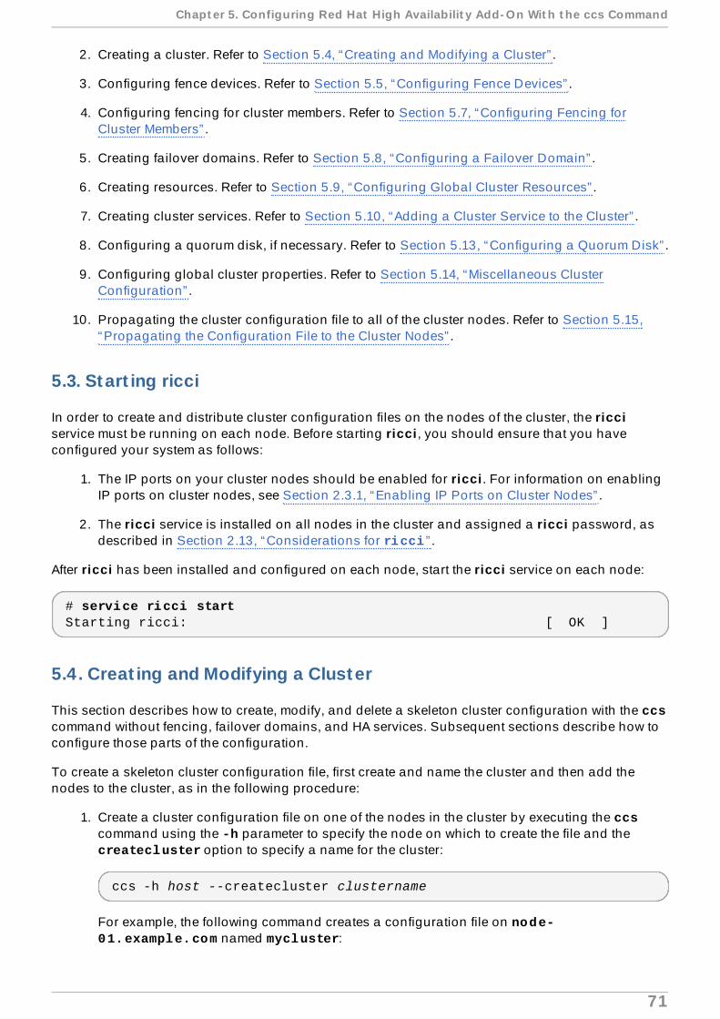
2. Creating a cluster. Refer to Section 5.4, “Creating and Modifying a Cluster” .
3. Configuring fence devices. Refer to Section 5.5, “Configuring Fence Devices” .
4. Configuring fencing for cluster members. Refer to Section 5.7, “Configuring Fencing forCluster Members” .
5. Creating failover domains. Refer to Section 5.8, “Configuring a Failover Domain” .
6. Creating resources. Refer to Section 5.9, “Configuring Global Cluster Resources” .
7. Creating cluster services. Refer to Section 5.10, “Adding a Cluster Service to the Cluster” .
8. Configuring a quorum disk, if necessary. Refer to Section 5.13, “Configuring a Quorum Disk” .
9. Configuring global cluster properties. Refer to Section 5.14, “Miscellaneous ClusterConfiguration” .
10. Propagating the cluster configuration file to all of the cluster nodes. Refer to Section 5.15,“Propagating the Configuration File to the Cluster Nodes” .
5.3. Start ing ricci
In order to create and distribute cluster configuration files on the nodes of the cluster, the ricciservice must be running on each node. Before starting ricci , you should ensure that you haveconfigured your system as follows:
1. The IP ports on your cluster nodes should be enabled for ricci . For information on enablingIP ports on cluster nodes, see Section 2.3.1, “Enabling IP Ports on Cluster Nodes” .
2. The ricci service is installed on all nodes in the cluster and assigned a ricci password, asdescribed in Section 2.13, “Considerations for ricci ” .
After ricci has been installed and configured on each node, start the ricci service on each node:
# service ricci startStarting ricci: [ OK ]
5.4 . Creat ing and Modifying a Cluster
This section describes how to create, modify, and delete a skeleton cluster configuration with the ccscommand without fencing, failover domains, and HA services. Subsequent sections describe how toconfigure those parts of the configuration.
To create a skeleton cluster configuration file, first create and name the cluster and then add thenodes to the cluster, as in the following procedure:
1. Create a cluster configuration file on one of the nodes in the cluster by executing the ccscommand using the -h parameter to specify the node on which to create the file and the createcluster option to specify a name for the cluster:
ccs -h host --createcluster clustername
For example, the following command creates a configuration file on node-01.example.com named mycluster:
Chapt er 5. Configuring Red Hat High Availabilit y Add- On Wit h t he ccs Command
71

ccs -h node-01.example.com --createcluster mycluster
The cluster name cannot exceed 15 characters.
If a cluster.conf file already exists on the host that you specify, executing this commandwill replace that existing file.
If you want to create a cluster configuration file on your local system you can specify the -foption instead of the -h option. For information on creating the file locally, refer toSection 5.1.1, “Creating the Cluster Configuration File on a Local System” .
2. To configure the nodes that the cluster contains, execute the following command for eachnode in the cluster. A node name can be up to 255 bytes in length.
ccs -h host --addnode node
For example, the following three commands add the nodes node-01.example.com, node-02.example.com, and node-03.example.com to the configuration file on node-01.example.com:
ccs -h node-01.example.com --addnode node-01.example.comccs -h node-01.example.com --addnode node-02.example.comccs -h node-01.example.com --addnode node-03.example.com
To view a list of the nodes that have been configured for a cluster, execute the followingcommand:
ccs -h host --lsnodes
Example 5.1, “cluster.conf File After Adding Three Nodes” shows a cluster.confconfiguration file after you have created the cluster mycluster that contains the nodes node-01.example.com, node-02.example.com, and node-03.example.com.
Example 5.1. cluster.conf File Af ter Adding Three Nodes
<cluster name="mycluster" config_version="2"> <clusternodes> <clusternode name="node-01.example.com" nodeid="1"> <fence> </fence> </clusternode> <clusternode name="node-02.example.com" nodeid="2"> <fence> </fence> </clusternode> <clusternode name="node-03.example.com" nodeid="3"> <fence> </fence> </clusternode> </clusternodes> <fencedevices>
Red Hat Ent erprise Linux 6 Clust er Administ rat ion
72

</fencedevices> <rm> </rm></cluster>
When you add a node to the cluster, you can specify the number of votes the nodecontributes to determine whether there is a quorum. To set the number of votes for a clusternode, use the following command:
ccs -h host --addnode host --votes votes
When you add a node, the ccs assigns the node a unique integer that is used as the nodeidentifier. If you want to specify the node identifier manually when creating a node, use thefollowing command:
ccs -h host --addnode host --nodeid nodeid
To remove a node from a cluster, execute the following command:
ccs -h host --rmnode node
When you have finished configuring all of the components of your cluster, you will need to sync thecluster configuration file to all of the nodes, as described in Section 5.15, “Propagating theConfiguration File to the Cluster Nodes” .
5.5. Configuring Fence Devices
Configuring fence devices consists of creating, updating, and deleting fence devices for the cluster.You must create and name the fence devices in a cluster before you can configure fencing for thenodes in the cluster. For information on configuring fencing for the individual nodes in the cluster,refer to Section 5.7, “Configuring Fencing for Cluster Members” .
Before configuring your fence devices, you may want to modify some of the fence daemon propertiesfor your system from the default values. The values you configure for the fence daemon are generalvalues for the cluster. The general fencing properties for the cluster you may want to modify aresummarized as follows:
The post_fail_delay attribute is the number of seconds the fence daemon (fenced ) waitsbefore fencing a node (a member of the fence domain) after the node has failed. The post_fail_delay default value is 0 . Its value may be varied to suit cluster and networkperformance.
The post-join_delay attribute is the number of seconds the fence daemon (fenced ) waitsbefore fencing a node after the node joins the fence domain. The post_join_delay defaultvalue is 6 . A typical setting for post_join_delay is between 20 and 30 seconds, but can varyaccording to cluster and network performance.
You reset the values of the post_fail_delay and post_join_delay attributes with the --setfencedaemon option of the ccs command. Note, however, that executing the ccs --setfencedaemon command overwrites all existing fence daemon properties that have beenexplicitly set and restores them to their default values.
Chapt er 5. Configuring Red Hat High Availabilit y Add- On Wit h t he ccs Command
73

For example, to configure a value for the post_fail_delay attribute, execute the followingcommand. This command will overwrite the values of all other existing fence daemon properties thatyou have set with this command and restore them to their default values.
ccs -h host --setfencedaemon post_fail_delay=value
To configure a value for the post_join_delay attribute, execute the following command. Thiscommand will overwrite the values of all other existing fence daemon properties that you have setwith this command and restore them to their default values.
ccs -h host --setfencedaemon post_join_delay=value
To configure a value for both the the post_join_delay attribute and the post_fail_delayattribute, execute the following command:
ccs -h host --setfencedaemon post_fail_delay=value post_join_delay=value
Note
For more information about the post_join_delay and post_fail_delay attributes aswell as the additional fence daemon properties you can modify, refer to the fenced(8) manpage and refer to the cluster schema at /usr/share/cluster/cluster.rng , and theannotated schema at /usr/share/doc/cman-X.Y.ZZ/cluster_conf.html .
To configure a fence device for a cluster, execute the following command:
ccs -h host --addfencedev devicename [fencedeviceoptions]
For example, to configure an APC fence device in the configuration file on the cluster node node1named my_apc with an IP address of apc_ip_example, a login of login_example, and apassword of password_example, execute the following command:
ccs -h node1 --addfencedev myfence agent=fence_apc ipaddr=apc_ip_example login=login_example passwd=password_example
The following example shows the fencedevices section of the cluster.conf configuration fileafter you have added this APC fence device:
<fencedevices> <fencedevice agent="fence_apc" ipaddr="apc_ip_example" login="login_example" name="my_apc" passwd="password_example"/></fencedevices>
When configuring fence devices for a cluster, you may find it useful to see a listing of availabledevices for your cluster and the options available for each device. You may also find it useful to seea listing of fence devices currently configured for your cluster. For information on using the ccscommand to print a list of available fence devices and options or to print a list of fence devicescurrently configured for your cluster, refer to Section 5.6, “Listing Fence Devices and Fence DeviceOptions” .
To remove a fence device from your cluster configuration, execute the following command:
Red Hat Ent erprise Linux 6 Clust er Administ rat ion
74

ccs -h host --rmfencedev fence_device_name
For example, to remove a fence device that you have named myfence from the cluster configurationfile on cluster node node1, execute the following command:
ccs -h node1 --rmfencedev myfence
If you need to modify the attributes of a fence device you have already configured, you must firstremove that fence device then add it again with the modified attributes.
Note that when you have finished configuring all of the components of your cluster, you will need tosync the cluster configuration file to all of the nodes, as described in Section 5.15, “Propagating theConfiguration File to the Cluster Nodes” .
5.6. List ing Fence Devices and Fence Device Opt ions
You can use the ccs command to print a list of available fence devices and to print a list of optionsfor each available fence type. You can also use the ccs command to print a list of fence devicescurrently configured for your cluster.
To print a list of fence devices currently available for your cluster, execute the following command:
ccs -h host --lsfenceopts
For example, the following command lists the fence devices available on the cluster node node1,showing sample output.
[root@ask-03 ~]# ccs -h node1 --lsfenceoptsfence_rps10 - RPS10 Serial Switchfence_vixel - No description availablefence_egenera - No description availablefence_xcat - No description availablefence_na - Node Assassinfence_apc - Fence agent for APC over telnet/sshfence_apc_snmp - Fence agent for APC over SNMPfence_bladecenter - Fence agent for IBM BladeCenterfence_bladecenter_snmp - Fence agent for IBM BladeCenter over SNMPfence_cisco_mds - Fence agent for Cisco MDSfence_cisco_ucs - Fence agent for Cisco UCSfence_drac5 - Fence agent for Dell DRAC CMC/5fence_eps - Fence agent for ePowerSwitchfence_ibmblade - Fence agent for IBM BladeCenter over SNMPfence_ifmib - Fence agent for IF MIBfence_ilo - Fence agent for HP iLOfence_ilo_mp - Fence agent for HP iLO MPfence_intelmodular - Fence agent for Intel Modularfence_ipmilan - Fence agent for IPMI over LANfence_kdump - Fence agent for use with kdumpfence_rhevm - Fence agent for RHEV-M REST APIfence_rsa - Fence agent for IBM RSAfence_sanbox2 - Fence agent for QLogic SANBox2 FC switchesfence_scsi - fence agent for SCSI-3 persistent reservationsfence_virsh - Fence agent for virshfence_virt - Fence agent for virtual machines
Chapt er 5. Configuring Red Hat High Availabilit y Add- On Wit h t he ccs Command
75

fence_vmware - Fence agent for VMwarefence_vmware_soap - Fence agent for VMware over SOAP APIfence_wti - Fence agent for WTIfence_xvm - Fence agent for virtual machines
To print a list of the options you can specify for a particular fence type, execute the followingcommand:
ccs -h host --lsfenceopts fence_type
For example, the following command lists the fence options for the fence_wti fence agent.
[root@ask-03 ~]# ccs -h node1 --lsfenceopts fence_wtifence_wti - Fence agent for WTI Required Options: Optional Options: option: No description available action: Fencing Action ipaddr: IP Address or Hostname login: Login Name passwd: Login password or passphrase passwd_script: Script to retrieve password cmd_prompt: Force command prompt secure: SSH connection identity_file: Identity file for ssh port: Physical plug number or name of virtual machine inet4_only: Forces agent to use IPv4 addresses only inet6_only: Forces agent to use IPv6 addresses only ipport: TCP port to use for connection with device verbose: Verbose mode debug: Write debug information to given file version: Display version information and exit help: Display help and exit separator: Separator for CSV created by operation list power_timeout: Test X seconds for status change after ON/OFF shell_timeout: Wait X seconds for cmd prompt after issuing command login_timeout: Wait X seconds for cmd prompt after login power_wait: Wait X seconds after issuing ON/OFF delay: Wait X seconds before fencing is started retry_on: Count of attempts to retry power on
To print a list of fence devices currently configured for your cluster, execute the following command:
ccs -h host --lsfencedev
5.7. Configuring Fencing for Cluster Members
Once you have completed the initial steps of creating a cluster and creating fence devices, you needto configure fencing for the cluster nodes. To configure fencing for the nodes after creating a newcluster and configuring the fencing devices for the cluster, follow the steps in this section. Note thatyou must configure fencing for each node in the cluster.
Red Hat Ent erprise Linux 6 Clust er Administ rat ion
76

Note
It is recommended that you configure multiple fencing mechanisms for each node. A fencingdevice can fail due to network split, a power outage, or a problem in the fencing device itself.Configuring multiple fencing mechanisms can reduce the likelihood that the failure of afencing device will have fatal results.
This section documents the following procedures:
Section 5.7.1, “Configuring a Single Power-Based Fence Device for a Node”
Section 5.7.2, “Configuring a Single Storage-Based Fence Device for a Node”
Section 5.7.3, “Configuring a Backup Fence Device”
Section 5.7.4, “Configuring a Node with Redundant Power”
Section 5.7.6, “Removing Fence Methods and Fence Instances”
5.7.1. Configuring a Single Power-Based Fence Device for a Node
Use the following procedure to configure a node with a single power-based fence device. The fencedevice is named my_apc, which uses the fence_apc fencing agent. In this example, the devicenamed my_apc was previously configured with the --addfencedev option, as described inSection 5.5, “Configuring Fence Devices” .
1. Add a fence method for the node, providing a name for the fence method.
ccs -h host --addmethod method node
For example, to configure a fence method named APC for the node node-01.example.comin the configuration file on the cluster node node-01.example.com, execute the followingcommand:
ccs -h node01.example.com --addmethod APC node01.example.com
2. Add a fence instance for the method. You must specify the fence device to use for the node,the node this instance applies to, the name of the method, and any options for this methodthat are specific to this node:
ccs -h host --addfenceinst fencedevicename node method [options]
For example, to configure a fence instance in the configuration file on the cluster node node-01.example.com that uses power port 1 on the APC switch for the fence device named my_apc to fence cluster node node-01.example.com using the method named APC ,execute the following command:
ccs -h node01.example.com --addfenceinst my_apc node01.example.com APC port=1
You will need to add a fence method for each node in the cluster. The following commands configurea fence method for each node with the method name APC . The device for the fence method specifies my_apc as the device name, which is a device previously configured with the --addfencedev
Chapt er 5. Configuring Red Hat High Availabilit y Add- On Wit h t he ccs Command
77

option, as described in Section 5.5, “Configuring Fence Devices” . Each node is configured with aunique APC switch power port number: The port number for node-01.example.com is 1, the portnumber for node-02.example.com is 2, and the port number for node-03.example.com is 3.
ccs -h node01.example.com --addmethod APC node01.example.comccs -h node01.example.com --addmethod APC node02.example.comccs -h node01.example.com --addmethod APC node03.example.comccs -h node01.example.com --addfenceinst my_apc node01.example.com APC port=1ccs -h node01.example.com --addfenceinst my_apc node02.example.com APC port=2ccs -h node01.example.com --addfenceinst my_apc node03.example.com APC port=3
Example 5.2, “cluster.conf After Adding Power-Based Fence Methods ” shows a cluster.confconfiguration file after you have added these fencing methods and instances to each node in thecluster.
Example 5.2. cluster.conf Af ter Adding Power-Based Fence Methods
<cluster name="mycluster" config_version="3"> <clusternodes> <clusternode name="node-01.example.com" nodeid="1"> <fence> <method name="APC"> <device name="my_apc" port="1"/> </method> </fence> </clusternode> <clusternode name="node-02.example.com" nodeid="2"> <fence> <method name="APC"> <device name="my_apc" port="2"/> </method> </fence> </clusternode> <clusternode name="node-03.example.com" nodeid="3"> <fence> <method name="APC"> <device name="my_apc" port="3"/> </method> </fence> </clusternode> </clusternodes> <fencedevices> <fencedevice agent="fence_apc" ipaddr="apc_ip_example" login="login_example" name="my_apc" passwd="password_example"/> </fencedevices> <rm> </rm></cluster>
Note that when you have finished configuring all of the components of your cluster, you will need to
Red Hat Ent erprise Linux 6 Clust er Administ rat ion
78

sync the cluster configuration file to all of the nodes, as described in Section 5.15, “Propagating theConfiguration File to the Cluster Nodes” .
5.7.2. Configuring a Single Storage-Based Fence Device for a Node
When using non-power fencing methods (that is, SAN/storage fencing) to fence a node, you mustconfigure unfencing for the fence device. This ensures that a fenced node is not re-enabled until thenode has been rebooted. When you configure a device that requires unfencing, the cluster must firstbe stopped and the full configuration including devices and unfencing must be added before thecluster is started.
When you configure unfencing for a node, you specify a device that mirrors the corresponding fencedevice you have configured for the node with the notable addition of the explicit action of on or enable.
For more information about unfencing a node, refer to the fence_node(8) man page.
Use the following procedure to configure a node with a single storage-based fence device that uses afence device named sanswitch1, which uses the fence_sanbox2 fencing agent.
1. Add a fence method for the node, providing a name for the fence method.
ccs -h host --addmethod method node
For example, to configure a fence method named SAN for the node node-01.example.comin the configuration file on the cluster node node-01.example.com, execute the followingcommand:
ccs -h node01.example.com --addmethod SAN node01.example.com
2. Add a fence instance for the method. You must specify the fence device to use for the node,the node this instance applies to, the name of the method, and any options for this methodthat are specific to this node:
ccs -h host --addfenceinst fencedevicename node method [options]
For example, to configure a fence instance in the configuration file on the cluster node node-01.example.com that uses the SAN switch power port 11 on the fence device named sanswitch1 to fence cluster node node-01.example.com using the method named SAN,execute the following command:
ccs -h node01.example.com --addfenceinst sanswitch1 node01.example.com SAN port=11
3. To configure unfencing for the storage-based fence device on this node, execute thefollowing command:
ccs -h host --addunfence fencedevicename node action=on|off
You will need to add a fence method for each node in the cluster. The following commands configurea fence method for each node with the method name SAN. The device for the fence method specifies sanswitch as the device name, which is a device previously configured with the --addfencedevoption, as described in Section 5.5, “Configuring Fence Devices” . Each node is configured with a
Chapt er 5. Configuring Red Hat High Availabilit y Add- On Wit h t he ccs Command
79

unique SAN physical port number: The port number for node-01.example.com is 11, the portnumber for node-02.example.com is 12, and the port number for node-03.example.com is 13.
ccs -h node01.example.com --addmethod SAN node01.example.comccs -h node01.example.com --addmethod SAN node02.example.comccs -h node01.example.com --addmethod SAN node03.example.comccs -h node01.example.com --addfenceinst sanswitch1 node01.example.com SAN port=11ccs -h node01.example.com --addfenceinst sanswitch1 node02.example.com SAN port=12ccs -h node01.example.com --addfenceinst sanswitch1 node03.example.com SAN port=13ccs -h node01.example.com --addunfence sanswitch1 node01.example.com port=11 action=onccs -h node01.example.com --addunfence sanswitch1 node02.example.com port=12 action=onccs -h node01.example.com --addunfence sanswitch1 node03.example.com port=13 action=on
Example 5.3, “cluster.conf After Adding Storage-Based Fence Methods ” shows a cluster.conf configuration file after you have added fencing methods, fencing instances, andunfencing to each node in the cluster.
Example 5.3. cluster.conf Af ter Adding Storage-Based Fence Methods
<cluster name="mycluster" config_version="3"> <clusternodes> <clusternode name="node-01.example.com" nodeid="1"> <fence> <method name="SAN"> <device name="sanswitch1" port="11"/> </method> </fence> <unfence> <device name="sanswitch1" port="11" action="on"/> </unfence> </clusternode> <clusternode name="node-02.example.com" nodeid="2"> <fence> <method name="SAN"> <device name="sanswitch1" port="12"/> </method> </fence> <unfence> <device name="sanswitch1" port="12" action="on"/> </unfence> </clusternode> <clusternode name="node-03.example.com" nodeid="3"> <fence> <method name="SAN"> <device name="sanswitch1" port="13"/> </method> </fence>
Red Hat Ent erprise Linux 6 Clust er Administ rat ion
80

<unfence> <device name="sanswitch1" port="13" action="on"/> </unfence> </clusternode> </clusternodes> <fencedevices> <fencedevice agent="fence_sanbox2" ipaddr="san_ip_example"login="login_example" name="sanswitch1" passwd="password_example"/> </fencedevices> <rm> </rm></cluster>
Note that when you have finished configuring all of the components of your cluster, you will need tosync the cluster configuration file to all of the nodes, as described in Section 5.15, “Propagating theConfiguration File to the Cluster Nodes” .
5.7.3. Configuring a Backup Fence Device
You can define multiple fencing methods for a node. If fencing fails using the first method, the systemwill attempt to fence the node using the second method, followed by any additional methods youhave configured. To configure a backup fencing method for a node, you configure two methods for anode, configuring a fence instance for each method.
Note
The order in which the system will use the fencing methods you have configured follows theirorder in the cluster configuration file. The first method you configure with the ccs command isthe primary fencing method, and the second method you configure is the backup fencingmethod. To change the order, you can remove the primary fencing method from theconfiguration file, then add that method back.
Note that at any time you can print a list of fence methods and instances currently configured for anode by executing the following command. If you do not specify a node, this command will list thefence methods and instances currently configured for all nodes.
ccs -h host --lsfenceinst [node]
Use the following procedure to configure a node with a primary fencing method that uses a fencedevice named my_apc, which uses the fence_apc fencing agent, and a backup fencing device thatuses a fence device named sanswitch1, which uses the fence_sanbox2 fencing agent. Since the sanswitch1 device is a storage-based fencing agent, you will need to configure unfencing for thatdevice as well.
1. Add a primary fence method for the node, providing a name for the fence method.
ccs -h host --addmethod method node
For example, to configure a fence method named APC as the primary method for the node node-01.example.com in the configuration file on the cluster node node-01.example.com, execute the following command:
Chapt er 5. Configuring Red Hat High Availabilit y Add- On Wit h t he ccs Command
81

ccs -h node01.example.com --addmethod APC node01.example.com
2. Add a fence instance for the primary method. You must specify the fence device to use for thenode, the node this instance applies to, the name of the method, and any options for thismethod that are specific to this node:
ccs -h host --addfenceinst fencedevicename node method [options]
For example, to configure a fence instance in the configuration file on the cluster node node-01.example.com that uses the APC switch power port 1 on the fence device named my_apcto fence cluster node node-01.example.com using the method named APC , execute thefollowing command:
ccs -h node01.example.com --addfenceinst my_apc node01.example.com APC port=1
3. Add a backup fence method for the node, providing a name for the fence method.
ccs -h host --addmethod method node
For example, to configure a backup fence method named SAN for the node node-01.example.com in the configuration file on the cluster node node-01.example.com,execute the following command:
ccs -h node01.example.com --addmethod SAN node01.example.com
4. Add a fence instance for the backup method. You must specify the fence device to use for thenode, the node this instance applies to, the name of the method, and any options for thismethod that are specific to this node:
ccs -h host --addfenceinst fencedevicename node method [options]
For example, to configure a fence instance in the configuration file on the cluster node node-01.example.com that uses the SAN switch power port 11 on the fence device named sanswitch1 to fence cluster node node-01.example.com using the method named SAN,execute the following command:
ccs -h node01.example.com --addfenceinst sanswitch1 node01.example.com SAN port=11
5. Since the sanswitch1 device is a storage-based device, you must configure unfencing forthis device.
ccs -h node01.example.com --addunfence sanswitch1 node01.example.com port=11 action=on
You can continue to add fencing methods as needed.
This procedure configures a fence device and a backup fence device for one node in the cluster. Youwill need to configure fencing for the other nodes in the cluster as well.
Red Hat Ent erprise Linux 6 Clust er Administ rat ion
82

Example 5.4, “cluster.conf After Adding Backup Fence Methods ” shows a cluster.confconfiguration file after you have added a power-based primary fencing method and a storage-basedbackup fencing method to each node in the cluster.
Example 5.4 . cluster.conf Af ter Adding Backup Fence Methods
<cluster name="mycluster" config_version="3"> <clusternodes> <clusternode name="node-01.example.com" nodeid="1"> <fence> <method name="APC"> <device name="my_apc" port="1"/> </method> <method name="SAN"> <device name="sanswitch1" port="11"/> </method> </fence> <unfence> <device name="sanswitch1" port="11" action="on"/> </unfence </clusternode> <clusternode name="node-02.example.com" nodeid="2"> <fence> <method name="APC"> <device name="my_apc" port="2"/> </method> <method name="SAN"> <device name="sanswitch1" port="12"/> </method> </fence> <unfence> <device name="sanswitch1" port="12" action="on"/> </unfence </clusternode> <clusternode name="node-03.example.com" nodeid="3"> <fence> <method name="APC"> <device name="my_apc" port="3"/> </method> <method name="SAN"> <device name="sanswitch1" port="13"/> </method> </fence> <unfence> <device name="sanswitch1" port="13" action="on"/> </unfence </clusternode> </clusternodes> <fencedevices> <fencedevice agent="fence_apc" ipaddr="apc_ip_example" login="login_example" name="my_apc" passwd="password_example"/> <fencedevice agent="fence_sanbox2" ipaddr="san_ip_example" login="login_example" name="sanswitch1" passwd="password_example"/> </fencedevices>
Chapt er 5. Configuring Red Hat High Availabilit y Add- On Wit h t he ccs Command
83

<rm> </rm></cluster>
Note that when you have finished configuring all of the components of your cluster, you will need tosync the cluster configuration file to all of the nodes, as described in Section 5.15, “Propagating theConfiguration File to the Cluster Nodes” .
Note
The order in which the system will use the fencing methods you have configured follows theirorder in the cluster configuration file. The first method you configure is the primary fencingmethod, and the second method you configure is the backup fencing method. To change theorder, you can remove the primary fencing method from the configuration file, then add thatmethod back.
5.7.4 . Configuring a Node with Redundant Power
If your cluster is configured with redundant power supplies for your nodes, you must be sure toconfigure fencing so that your nodes fully shut down when they need to be fenced. If you configureeach power supply as a separate fence method, each power supply will be fenced separately; thesecond power supply will allow the system to continue running when the first power supply is fencedand the system will not be fenced at all. To configure a system with dual power supplies, you mustconfigure your fence devices so that both power supplies are shut off and the system is takencompletely down. This requires that you configure two instances within a single fencing method, andthat for each instance you configure both fence devices with an action attribute of off beforeconfiguring each of the devices with an action attribute of on.
To configure fencing for a node with dual power supplies, follow the steps in this section.
1. Before you can configure fencing for a node with redundant power, you must configure eachof the power switches as a fence device for the cluster. For information on configuring fencedevices, see Section 5.5, “Configuring Fence Devices” .
To print a list of fence devices currently configured for your cluster, execute the followingcommand:
ccs -h host --lsfencedev
2. Add a fence method for the node, providing a name for the fence method.
ccs -h host --addmethod method node
For example, to configure a fence method named APC-dual for the node node-01.example.com in the configuration file on the cluster node node-01.example.com,execute the following command:
ccs -h node01.example.com --addmethod APC-dual node01.example.com
Red Hat Ent erprise Linux 6 Clust er Administ rat ion
84

3. Add a fence instance for the first power supply to the fence method. You must specify thefence device to use for the node, the node this instance applies to, the name of the method,and any options for this method that are specific to this node. At this point you configure the action attribute as off.
ccs -h host --addfenceinst fencedevicename node method [options] action=off
For example, to configure a fence instance in the configuration file on the cluster node node-01.example.com that uses the APC switch power port 1 on the fence device named apc1 tofence cluster node node-01.example.com using the method named APC-dual , andsetting the action attribute to off, execute the following command:
ccs -h node01.example.com --addfenceinst apc1 node01.example.com APC-dual port=1 action=off
4. Add a fence instance for the second power supply to the fence method. You must specify thefence device to use for the node, the node this instance applies to, the name of the method,and any options for this method that are specific to this node. At this point you configure the action attribute as off for this instance as well:
ccs -h host --addfenceinst fencedevicename node method [options] action=off
For example, to configure a second fence instance in the configuration file on the clusternode node-01.example.com that uses the APC switch power port 1 on the fence devicenamed apc2 to fence cluster node node-01.example.com using the same method as youspecified for the first instance named APC-dual , and setting the action attribute to off,execute the following command:
ccs -h node01.example.com --addfenceinst apc2 node01.example.com APC-dual port=1 action=off
5. At this point, add another fence instance for the first power supply to the fence method,configuring the action attribute as on. You must specify the fence device to use for thenode, the node this instance applies to, the name of the method, and any options for thismethod that are specific to this node, and specifying the action attribute as on:
ccs -h host --addfenceinst fencedevicename node method [options] action=on
For example, to configure a fence instance in the configuration file on the cluster node node-01.example.com that uses the APC switch power port 1 on the fence device named apc1 tofence cluster node node-01.example.com using the method named APC-dual , andsetting the action attribute to on, execute the following command:
ccs -h node01.example.com --addfenceinst apc1 node01.example.com APC-dual port=1 action=on
6. Add another fence instance for second power supply to the fence method, specifying the action attribute as on for this instance. You must specify the fence device to use for thenode, the node this instance applies to, the name of the method, and any options for thismethod that are specific to this node as well as the action attribute of on.
Chapt er 5. Configuring Red Hat High Availabilit y Add- On Wit h t he ccs Command
85

ccs -h host --addfenceinst fencedevicename node method [options] action=on
For example, to configure a second fence instance in the configuration file on the clusternode node-01.example.com that uses the APC switch power port 1 on the fence devicenamed apc2 to fence cluster node node-01.example.com using the same method as youspecified for the first instance named APC-dual and setting the action attribute to on,execute the following command:
ccs -h node01.example.com --addfenceinst apc2 node01.example.com APC-dual port=1 action=on
Example 5.5, “cluster.conf After Adding Dual-Power Fencing ” shows a cluster.confconfiguration file after you have added fencing for two power supplies for each node in a cluster.
Example 5.5. cluster.conf Af ter Adding Dual-Power Fencing
<cluster name="mycluster" config_version="3"> <clusternodes> <clusternode name="node-01.example.com" nodeid="1"> <fence> <method name="APC-dual"> <device name="apc1" port="1"action="off"/> <device name="apc2" port="1"action="off"/> <device name="apc1" port="1"action="on"/> <device name="apc2" port="1"action="on"/> </method> </fence> </clusternode> <clusternode name="node-02.example.com" nodeid="2"> <fence> <method name="APC-dual"> <device name="apc1" port="2"action="off"/> <device name="apc2" port="2"action="off"/> <device name="apc1" port="2"action="on"/> <device name="apc2" port="2"action="on"/> </method> </fence> </clusternode> <clusternode name="node-03.example.com" nodeid="3"> <fence> <method name="APC-dual"> <device name="apc1" port="3"action="off"/> <device name="apc2" port="3"action="off"/> <device name="apc1" port="3"action="on"/> <device name="apc2" port="3"action="on"/> </method> </fence> </clusternode> </clusternodes> <fencedevices> <fencedevice agent="fence_apc" ipaddr="apc_ip_example" login="login_example" name="apc1" passwd="password_example"/>
Red Hat Ent erprise Linux 6 Clust er Administ rat ion
86

<fencedevice agent="fence_apc" ipaddr="apc_ip_example" login="login_example" name="apc2" passwd="password_example"/> </fencedevices> <rm> </rm></cluster>
Note that when you have finished configuring all of the components of your cluster, you will need tosync the cluster configuration file to all of the nodes, as described in Section 5.15, “Propagating theConfiguration File to the Cluster Nodes” .
5.7.5. T est ing the Fence Configurat ion
As of Red Hat Enterprise Linux Release 6.4, you can test the fence configuration for each node in acluster with the fence_check utility.
The following example shows the output of a successful execution of this command.
[root@host-098 ~]# fence_checkfence_check run at Wed Jul 23 09:13:57 CDT 2014 pid: 4769Testing host-098 method 1: successTesting host-099 method 1: successTesting host-100 method 1: success
For information on this utility, see the fence_check(8) man page.
5.7.6. Removing Fence Methods and Fence Instances
To remove a fence method from your cluster configuration, execute the following command:
ccs -h host --rmmethod method node
For example, to remove a fence method that you have named APC that you have configured for node01.example.com from the cluster configuration file on cluster node node01.example.com, execute the following command:
ccs -h node01.example.com --rmmethod APC node01.example.com
To remove all fence instances of a fence device from a fence method, execute the following command:
ccs -h host --rmfenceinst fencedevicename node method
For example, to remove all instances of the fence device named apc1 from the method named APC-dual configured for node01.example.com from the cluster configuration file on cluster node node01.example.com, execute the following command:
ccs -h node01.example.com --rmfenceinst apc1 node01.example.com APC-dual
5.8. Configuring a Failover Domain
Chapt er 5. Configuring Red Hat High Availabilit y Add- On Wit h t he ccs Command
87

A failover domain is a named subset of cluster nodes that are eligible to run a cluster service in theevent of a node failure. A failover domain can have the following characteristics:
Unrestricted — Allows you to specify that a subset of members are preferred, but that a clusterservice assigned to this domain can run on any available member.
Restricted — Allows you to restrict the members that can run a particular cluster service. If none ofthe members in a restricted failover domain are available, the cluster service cannot be started(either manually or by the cluster software).
Unordered — When a cluster service is assigned to an unordered failover domain, the member onwhich the cluster service runs is chosen from the available failover domain members with nopriority ordering.
Ordered — Allows you to specify a preference order among the members of a failover domain. Themember at the top of the list is the most preferred, followed by the second member in the list, andso on.
Failback — Allows you to specify whether a service in the failover domain should fail back to thenode that it was originally running on before that node failed. Configuring this characteristic isuseful in circumstances where a node repeatedly fails and is part of an ordered failover domain.In that circumstance, if a node is the preferred node in a failover domain, it is possible for aservice to fail over and fail back repeatedly between the preferred node and another node,causing severe impact on performance.
Note
The failback characteristic is applicable only if ordered failover is configured.
Note
Changing a failover domain configuration has no effect on currently running services.
Note
Failover domains are not required for operation.
By default, failover domains are unrestricted and unordered.
In a cluster with several members, using a restricted failover domain can minimize the work to set upthe cluster to run a cluster service (such as httpd ) which requires you to set up the configurationidentically on all members that run the cluster service. Instead of setting up the entire cluster to runthe cluster service, you can set up only the members in the restricted failover domain that youassociate with the cluster service.
Red Hat Ent erprise Linux 6 Clust er Administ rat ion
88

Note
To configure a preferred member, you can create an unrestricted failover domain comprisingonly one cluster member. Doing that causes a cluster service to run on that cluster memberprimarily (the preferred member), but allows the cluster service to fail over to any of the othermembers.
To configure a failover domain, perform the following procedure:
1. To add a failover domain, execute the following command:
ccs -h host --addfailoverdomain name [restricted] [ordered] [nofailback]
Note
The name should be descriptive enough to distinguish its purpose relative to othernames used in your cluster.
For example, the following command configures a failover domain named example_pri on node-01.example.com that is unrestricted, ordered, and allows failback:
ccs -h node-01.example.com --addfailoverdomain example_pri ordered
2. To add a node to a failover domain, execute the following command:
ccs -h host --addfailoverdomainnode failoverdomain node priority
For example, to configure the failover domain example_pri in the configuration file on node-01.example.com so that it contains node-01.example.com with a priority of 1, node-02.example.com with a priority of 2, and node-03.example.com with a priorityof 3, execute the following commands:
ccs -h node-01.example.com --addfailoverdomainnode example_pri node-01.example.com 1ccs -h node-01.example.com --addfailoverdomainnode example_pri node-02.example.com 2ccs -h node-01.example.com --addfailoverdomainnode example_pri node-03.example.com 3
You can list all of the failover domains and failover domain nodes configured in a cluster with thefollowing command:
ccs -h host --lsfailoverdomain
To remove a failover domain, execute the following command:
ccs -h host --rmfailoverdomain name
To remove a node from a failover domain, execute the following command:
Chapt er 5. Configuring Red Hat High Availabilit y Add- On Wit h t he ccs Command
89

ccs -h host --rmfailoverdomainnode failoverdomain node
Note that when you have finished configuring all of the components of your cluster, you will need tosync the cluster configuration file to all of the nodes, as described in Section 5.15, “Propagating theConfiguration File to the Cluster Nodes” .
5.9. Configuring Global Cluster Resources
You can configure two types of resources:
Global — Resources that are available to any service in the cluster.
Service-specific — Resources that are available to only one service.
To see a list of currently configured resources and services in the cluster, execute the followingcommand:
ccs -h host --lsservices
To add a global cluster resource, execute the following command. You can add a resource that islocal to a particular service when you configure the service, as described in Section 5.10, “Adding aCluster Service to the Cluster” .
ccs -h host --addresource resourcetype [resource options]
For example, the following command adds a global file system resource to the cluster configurationfile on node01.example.com. The name of the resource is web_fs, the file system device is /dev/sdd2, the file system mountpoint is /var/www, and the file system type is ext3.
ccs -h node01.example.com --addresource fs name=web_fs device=/dev/sdd2 mountpoint=/var/www fstype=ext3
For information about the available resource types and resource options, see Appendix B, HAResource Parameters.
To remove a global resource, execute the following command:
ccs -h host --rmresource resourcetype [resource options]
If you need to modify the parameters of an existing global resource, you can remove the resourceand configure it again.
Note that when you have finished configuring all of the components of your cluster, you will need tosync the cluster configuration file to all of the nodes, as described in Section 5.15, “Propagating theConfiguration File to the Cluster Nodes” .
5.10. Adding a Cluster Service to the Cluster
To configure a cluster service in a cluster, perform the following steps:
1. Add a service to the cluster with the following command:
ccs -h host --addservice servicename [service options]
Red Hat Ent erprise Linux 6 Clust er Administ rat ion
90

Note
Use a descriptive name that clearly distinguishes the service from other services in thecluster.
When you add a service to the cluster configuration, you configure the following attributes:
autostart — Specifies whether to autostart the service when the cluster starts. Use "1" toenable and "0" to disable; the default is enabled.
domain — Specifies a failover domain (if required).
exclusive — Specifies a policy wherein the service only runs on nodes that have noother services running on them.
recovery — Specifies a recovery policy for the service. The options are to relocate,restart, disable, or restart-disable the service. The restart recovery policy indicates that thesystem should attempt to restart the failed service before trying to relocate the service toanother node. The relocate policy indicates that the system should try to restart the servicein a different node. The disable policy indicates that the system should disable theresource group if any component fails. The restart-disable policy indicates that the systemshould attempt to restart the service in place if it fails, but if restarting the service fails theservice will be disabled instead of being moved to another host in the cluster.
If you select Restart or Restart -Disable as the recovery policy for the service, you canspecify the maximum number of restart failures before relocating or disabling the service,and you can specify the length of time in seconds after which to forget a restart.
For example, to add a service to the configuration file on the cluster node node-01.example.com named example_apache that uses the failover domain example_pri ,and that has recovery policy of relocate, execute the following command:
ccs -h node-01.example.com --addservice example_apache domain=example_pri recovery=relocate
When configuring services for a cluster, you may find it useful to see a listing of availableservices for your cluster and the options available for each service. For information on usingthe ccs command to print a list of available services and their options, refer to Section 5.11,“Listing Available Cluster Services and Resources” .
2. Add resources to the service with the following command:
ccs -h host --addsubservice servicename subservice [service options]
Depending on the type of resources you want to use, populate the service with global orservice-specific resources. To add a global resource, use the --addsubservice option ofthe ccs to add a resource. For example, to add the global file system resource named web_fs to the service named example_apache on the cluster configuration file on node-01.example.com, execute the following command:
ccs -h node01.example.com --addsubservice example_apache fs ref=web_fs
To add a service-specific resource to the service, you need to specify all of the service
Chapt er 5. Configuring Red Hat High Availabilit y Add- On Wit h t he ccs Command
91

options. For example, if you had not previously defined web_fs as a global service, youcould add it as a service-specific resource with the following command:
ccs -h node01.example.com --addsubservice example_apache fs name=web_fs device=/dev/sdd2 mountpoint=/var/www fstype=ext3
3. To add a child service to the service, you also use the --addsubservice option of the ccscommand, specifying the service options.
If you need to add services within a tree structure of dependencies, use a colon (" :" ) toseparate elements and brackets to identify subservices of the same type. The followingexample adds a third nfsclient service as a subservice of an nfsclient service which isin itself a subservice of an nfsclient service which is a subservice of a service named service_a:
ccs -h node01.example.com --addsubservice service_a nfsclient[1]:nfsclient[2]:nfsclient
Note
If you are adding a Samba-service resource, add it directly to the service, not as a childof another resource.
Note
When configuring a dependency tree for a cluster service that includes a floating IPaddress resource, you must configure the IP resource as the first entry.
Note
To verify the existence of the IP service resource used in a cluster service, you can use the /sbin/ip addr show command on a cluster node (rather than the obsoleted ifconfigcommand). The following output shows the /sbin/ip addr show command executed on anode running a cluster service:
1: lo: <LOOPBACK,UP> mtu 16436 qdisc noqueue link/loopback 00:00:00:00:00:00 brd 00:00:00:00:00:00 inet 127.0.0.1/8 scope host lo inet6 ::1/128 scope host valid_lft forever preferred_lft forever2: eth0: <BROADCAST,MULTICAST,UP> mtu 1356 qdisc pfifo_fast qlen 1000 link/ether 00:05:5d:9a:d8:91 brd ff:ff:ff:ff:ff:ff inet 10.11.4.31/22 brd 10.11.7.255 scope global eth0 inet6 fe80::205:5dff:fe9a:d891/64 scope link inet 10.11.4.240/22 scope global secondary eth0 valid_lft forever preferred_lft forever
Red Hat Ent erprise Linux 6 Clust er Administ rat ion
92

To remove a service and all of its subservices, execute the following command:
ccs -h host --rmservice servicename
To remove a subservice, execute the following command:
ccs -h host --rmsubservice servicename subservice [service options]
Note that when you have finished configuring all of the components of your cluster, you will need tosync the cluster configuration file to all of the nodes, as described in Section 5.15, “Propagating theConfiguration File to the Cluster Nodes” .
5.11. List ing Available Cluster Services and Resources
You can use the ccs command to print a list of resources and services that are available for acluster. You can also use the ccs command to print a list of the options you can specify for aparticular service or resource type.
To print a list of cluster services currently available for your cluster, execute either of the followingcommands (--lsresourceopts is an alias to --lsserviceopts):
ccs -h host --lsserviceoptsccs -h host --lsresourceopts
For example, the following command lists the cluster services and resources available on the clusternode node1, showing sample output.
[root@ask-03 ~]# ccs -h node1 --lsserviceoptsservice - Defines a service (resource group).ASEHAagent - Sybase ASE Failover InstanceSAPDatabase - SAP database resource agentSAPInstance - SAP instance resource agentapache - Defines an Apache web serverclusterfs - Defines a cluster file system mount.fs - Defines a file system mount.ip - This is an IP address.lvm - LVM Failover scriptmysql - Defines a MySQL database servernamed - Defines an instance of named servernetfs - Defines an NFS/CIFS file system mount.nfsclient - Defines an NFS client.nfsexport - This defines an NFS export.nfsserver - This defines an NFS server resource.openldap - Defines an Open LDAP serveroracledb - Oracle 10g Failover Instanceorainstance - Oracle 10g Failover Instanceoralistener - Oracle 10g Listener Instancepostgres-8 - Defines a PostgreSQL serversamba - Dynamic smbd/nmbd resource agentscript - LSB-compliant init script as a clustered resource.tomcat-6 - Defines a Tomcat servervm - Defines a Virtual Machineaction - Overrides resource action timings for a resource instance.
Chapt er 5. Configuring Red Hat High Availabilit y Add- On Wit h t he ccs Command
93

To print a list of the options you can specify for a particular service type, execute the followingcommand:
ccs -h host --lsserviceopts service_type
For example, the following command lists the service options for the vm service.
[root@ask-03 ~]# ccs -f node1 --lsserviceopts vmvm - Defines a Virtual Machine Required Options: name: Name Optional Options: domain: Cluster failover Domain autostart: Automatic start after quorum formation exclusive: Exclusive resource group recovery: Failure recovery policy migration_mapping: memberhost:targethost,memberhost:targethost .. use_virsh: If set to 1, vm.sh will use the virsh command to manage virtual machines instead of xm. This is required when using non-Xen virtual machines (e.g. qemu / KVM). xmlfile: Full path to libvirt XML file describing the domain. migrate: Migration type (live or pause, default = live). path: Path to virtual machine configuration files. snapshot: Path to the snapshot directory where the virtual machine image will be stored. depend: Top-level service this depends on, in service:name format. depend_mode: Service dependency mode (soft or hard). max_restarts: Maximum restarts for this service. restart_expire_time: Restart expiration time; amount of time before a restart is forgotten. status_program: Additional status check program hypervisor: Hypervisor hypervisor_uri: Hypervisor URI (normally automatic). migration_uri: Migration URI (normally automatic). __independent_subtree: Treat this and all children as an independent subtree. __enforce_timeouts: Consider a timeout for operations as fatal. __max_failures: Maximum number of failures before returning a failure to a status check. __failure_expire_time: Amount of time before a failure is forgotten. __max_restarts: Maximum number restarts for an independent subtree before giving up. __restart_expire_time: Amount of time before a failure is forgotten for an independent subtree.
5.12. Virtual Machine Resources
Virtual machine resources are configured differently than other cluster resources. In particular, theyare not grouped into service definitions. As of the Red Hat Enterprise Linux 6.2 release, when youconfigure a virtual machine in a cluster with the ccs command you can use the --addvm (ratherthan the addservice option). This ensures that the vm resource is defined directly under the rmconfiguration node in the cluster configuration file.
Red Hat Ent erprise Linux 6 Clust er Administ rat ion
94

A virtual machine resource requires at least a name and a path attribute. The name attribute shouldmatch the name of the libvirt domain and the path attribute should specify the directory where theshared virtual machine definitions are stored.
Note
The path attribute in the cluster configuration file is a path specification or a directory name,not a path to an individual file.
If virtual machine definitions are stored on a shared directory named /mnt/vm_defs, the followingcommand will define a virtual machine named guest1:
# ccs -h node1.example.com --addvm guest1 path=/mnt/vm_defs
Running this command adds the following line to the rm configuration node in the cluster.conffile:
<vm name="guest1" path="/mnt/vm_defs"/>
5.13. Configuring a Quorum Disk
Important
Quorum-disk parameters and heuristics depend on the site environment and the specialrequirements needed. To understand the use of quorum-disk parameters and heuristics, referto the qdisk(5) man page. If you require assistance understanding and using quorum disk,contact an authorized Red Hat support representative.
Use the following command to configure your system for using a quorum disk:
ccs -h host --setquorumd [quorumd options]
Note that this command resets all other properties that you can set with the --setquorumd option totheir default values, as described in Section 5.1.5, “Commands that Overwrite Previous Settings” .
Table 5.1, “Quorum Disk Options” summarizes the meaning of the quorum disk options you mayneed to set. For a complete list of quorum disk parameters, refer to the cluster schema at /usr/share/cluster/cluster.rng , and the annotated schema at /usr/share/doc/cman-X.Y.ZZ/cluster_conf.html .
Table 5.1. Quorum Disk Opt ions
Parameter Descript ioninterval The frequency of read/write cycles, in seconds.votes The number of votes the quorum daemon advertises to cman when it has
a high enough score.tko The number of cycles a node must miss to be declared dead.
Chapt er 5. Configuring Red Hat High Availabilit y Add- On Wit h t he ccs Command
95

min_score The minimum score for a node to be considered "alive". If omitted or set to0, the default function, floor((n+1)/2), is used, where n is the sum ofthe heuristics scores. The Minimum Score value must never exceed thesum of the heuristic scores; otherwise, the quorum disk cannot beavailable.
device The storage device the quorum daemon uses. The device must be thesame on all nodes.
label Specifies the quorum disk label created by the mkqdisk utility. If this fieldcontains an entry, the label overrides the Device field. If this field is used,the quorum daemon reads /proc/partitions and checks for qdisksignatures on every block device found, comparing the label against thespecified label. This is useful in configurations where the quorum devicename differs among nodes.
Parameter Descript ion
Use the following command to configure the heuristics for a quorum disk:
ccs -h host --addheuristic [heuristic options]
Table 5.2, “Quorum Disk Heuristics” summarizes the meaning of the quorum disk heuristics you mayneed to set.
Table 5.2. Quorum Disk Heurist ics
Parameter Descript ionprogram The path to the program used to determine if this heuristic is available.
This can be anything that can be executed by /bin/sh -c. A returnvalue of 0 indicates success; anything else indicates failure. Thisparameter is required to use a quorum disk.
in terval The frequency (in seconds) at which the heuristic is polled. The defaultinterval for every heuristic is 2 seconds.
score The weight of this heuristic. Be careful when determining scores forheuristics. The default score for each heuristic is 1.
tko The number of consecutive failures required before this heuristic isdeclared unavailable.
To see a list of the quorum disk options and heuristics that are configured on a system, you canexecute the following command:
ccs -h host --lsquorum
To remove a heuristic specified by a heuristic option, you can execute the following command:
ccs -h host rmheuristic [heuristic options]
Note that when you have finished configuring all of the components of your cluster, you will need tosync the cluster configuration file to all of the nodes, as described in Section 5.15, “Propagating theConfiguration File to the Cluster Nodes” .
Red Hat Ent erprise Linux 6 Clust er Administ rat ion
96

Note
Syncing and activating propagates and activates the updated cluster configuration file.However, for the quorum disk to operate, you must restart the cluster (refer to Section 6.2,“Starting and Stopping a Cluster” ), ensuring that you have restarted the qdiskd daemon oneach node.
5.14. Miscellaneous Cluster Configurat ion
This section describes using the ccs command to configure the following:
Section 5.14.1, “Cluster Configuration Version”
Section 5.14.2, “Multicast Configuration”
Section 5.14.3, “Configuring a Two-Node Cluster”
Section 5.14.4, “Logging”
Section 5.14.5, “Configuring Redundant Ring Protocol”
You can also use the ccs command to set advanced cluster configuration parameters, including totem options, dlm options, rm options and cman options. For information on setting theseparameters see the ccs(8) man page and the annotated cluster configuration file schema at /usr/share/doc/cman-X.Y.ZZ/cluster_conf.html .
To view a list of the miscellaneous cluster attributes that have been configured for a cluster, executethe following command:
ccs -h host --lsmisc
5.14 .1. Cluster Configurat ion Version
A cluster configuration file includes a cluster configuration version value. The configuration versionvalue is set to 1 by default when you create a cluster configuration file and it is automaticallyincremented each time you modify your cluster configuration. However, if you need to set it to anothervalue, you can specify it with the following command:
ccs -h host --setversion n
You can get the current configuration version value on an existing cluster configuration file with thefollowing command:
ccs -h host --getversion
To increment the current configuration version value by 1 in the cluster configuration file on everynode in the cluster, execute the following command:
ccs -h host --incversion
5.14 .2. Mult icast Configurat ion
Chapt er 5. Configuring Red Hat High Availabilit y Add- On Wit h t he ccs Command
97

If you do not specify a multicast address in the cluster configuration file, the Red Hat High AvailabilityAdd-On software creates one based on the cluster ID. It generates the lower 16 bits of the addressand appends them to the upper portion of the address according to whether the IP protocol is IPv4 orIPv6:
For IPv4 — The address formed is 239.192. plus the lower 16 bits generated by Red Hat HighAvailability Add-On software.
For IPv6 — The address formed is FF15:: plus the lower 16 bits generated by Red Hat HighAvailability Add-On software.
Note
The cluster ID is a unique identifier that cman generates for each cluster. To view the clusterID, run the cman_tool status command on a cluster node.
You can manually specify a multicast address in the cluster configuration file with the followingcommand:
ccs -h host --setmulticast multicastaddress
Note that this command resets all other properties that you can set with the --setmulticast optionto their default values, as described in Section 5.1.5, “Commands that Overwrite Previous Settings” .
If you specify a multicast address, you should use the 239.192.x.x series (or FF15:: for IPv6) that cman uses. Otherwise, using a multicast address outside that range may cause unpredictableresults. For example, using 224.0.0.x (which is "All hosts on the network") may not be routedcorrectly, or even routed at all by some hardware.
If you specify or modify a multicast address, you must restart the cluster for this to take effect. Forinformation on starting and stopping a cluster with the ccs command, refer to Section 6.2, “Startingand Stopping a Cluster” .
Note
If you specify a multicast address, make sure that you check the configuration of routers thatcluster packets pass through. Some routers may take a long time to learn addresses, seriouslyimpacting cluster performance.
To remove a multicast address from a configuration file, use the --setmulticast option of the ccsbut do not specify a multicast address:
ccs -h host --setmulticast
5.14 .3. Configuring a T wo-Node Cluster
If you are configuring a two-node cluster, you can execute the following command to allow a singlenode to maintain quorum (for example, if one node fails):
ccs -h host --setcman two_node=1 expected_votes=1
Red Hat Ent erprise Linux 6 Clust er Administ rat ion
98

Note that this command resets all other properties that you can set with the --setcman option to theirdefault values, as described in Section 5.1.5, “Commands that Overwrite Previous Settings” .
When you use the ccs --setcman command to add, remove, or modify the two_node option, youmust restart the cluster for this change to take effect. For information on starting and stopping acluster with the ccs command, refer to Section 6.2, “Starting and Stopping a Cluster” .
5.14 .4 . Logging
You can enable debugging for all daemons in a cluster, or you can enable logging for specificcluster processing.
To enable debugging for all daemons, execute the following command. By default, logging isdirected to the /var/log/cluster/daemon.log file.
ccs -h host --setlogging [logging options]
For example, the following command enables debugging for all daemons.
# ccs -h node1.example.com --setlogging debug=on
Note that this command resets all other properties that you can set with the --setlogging optionto their default values, as described in Section 5.1.5, “Commands that Overwrite Previous Settings” .
To enable debugging for an individual cluster process, execute the following command. Per-daemonlogging configuration overrides the global settings.
ccs -h host --addlogging [logging daemon options]
For example, the following commands enable debugging for the corosync and fenced daemons.
# ccs -h node1.example.com --addlogging name=corosync debug=on# ccs -h node1.example.com --addlogging name=fenced debug=on
To remove the log settings for individual daemons, use the following command.
ccs -h host --rmlogging name=clusterprocess
For example, the following command removes the daemon-specific log settings for the fenceddaemaon
ccs -h host --rmlogging name=fenced
For a list of the logging daemons for which you can enable logging as well as the additional loggingoptions you can configure for both global and per-daemon logging, refer to the cluster.conf(5)man page.
Note that when you have finished configuring all of the components of your cluster, you will need tosync the cluster configuration file to all of the nodes, as described in Section 5.15, “Propagating theConfiguration File to the Cluster Nodes” .
5.14 .5. Configuring Redundant Ring Protocol
Chapt er 5. Configuring Red Hat High Availabilit y Add- On Wit h t he ccs Command
99

As of Red Hat Enterprise Linux 6.4, the Red Hat High Availability Add-On supports the configurationof redundant ring protocol. When using redundant ring protocol, there are a variety ofconsiderations you must take into account, as described in Section 7.6, “Configuring RedundantRing Protocol” .
To specify a second network interface to use for redundant ring protocol, you add an alternate namefor the node using the --addalt option of the ccs command:
ccs -h host --addalt node_name alt_name
For example, the following command configures the alternate name clusternet-node1-eth2 forthe cluster node clusternet-node1-eth1:
# ccs -h clusternet-node1-eth1 --addalt clusternet-node1-eth1 clusternet-node1-eth2
Optionally, you can manually specify a multicast address, a port, and a TTL for the second ring. Ifyou specify a multicast for the second ring, either the alternate multicast address or the alternate portmust be different from the multicast address for the first ring. If you specify an alternate port, the portnumbers of the first ring and the second ring must differ by at least two, since the system itself usesport and port-1 to perform operations. If you do not specify an alternate multicast address, the systemwill automatically use a different multicast address for the second ring.
To specify an alternate multicast address, port, or TTL for the second ring, you use the --setaltmulticast option of the ccs command:
ccs -h host --setaltmulticast [alt_multicast_address] [alt_multicast_options].
For example, the following command sets an alternate multicast address of 239.192.99.88, a port of888, and a TTL of 3 for the cluster defined in the cluster.conf file on node clusternet-node1-eth1:
ccs -h clusternet-node1-eth1 --setaltmulticast 239.192.99.88 port=888 ttl=3
To remove an alternate multicast address, specify the --setaltmulticast option of the ccscommand but do not specify a multicast address. Note that executing this command resets all otherproperties that you can set with the --setaltmulticast option to their default values, as describedin Section 5.1.5, “Commands that Overwrite Previous Settings” .
When you have finished configuring all of the components of your cluster, you will need to sync thecluster configuration file to all of the nodes, as described in Section 5.15, “Propagating theConfiguration File to the Cluster Nodes” .
5.15. Propagat ing the Configurat ion File to the Cluster Nodes
After you have created or edited a cluster configuration file on one of the nodes in the cluster, youneed to propagate that same file to all of the cluster nodes and activate the configuration.
Use the following command to propagate and activate a cluster configuration file. When you use the --activate option, you must also specify the --sync option for the activation to take affect.
ccs -h host --sync --activate
Red Hat Ent erprise Linux 6 Clust er Administ rat ion
100

To verify that all of the nodes specified in the hosts cluster configuration file have the identical clusterconfiguration file, execute the following command:
ccs -h host --checkconf
If you have created or edited a configuration file on a local node, use the following command to sendthat file to one of the nodes in the cluster:
ccs -f file -h host --setconf
To verify that all of the nodes specified in the local file have the identical cluster configuration file,execute the following command:
ccs -f file --checkconf
Chapt er 5. Configuring Red Hat High Availabilit y Add- On Wit h t he ccs Command
101

Chapter 6. Managing Red Hat High Availability Add-On With ccs
This chapter describes various administrative tasks for managing the Red Hat High Availability Add-On by means of the ccs command, which is supported as of the Red Hat Enterprise Linux 6.1 releaseand later. This chapter consists of the following sections:
Section 6.1, “Managing Cluster Nodes”
Section 6.2, “Starting and Stopping a Cluster”
Section 6.3, “Diagnosing and Correcting Problems in a Cluster”
6.1. Managing Cluster Nodes
This section documents how to perform the following node-management functions with the ccscommand:
Section 6.1.1, “Causing a Node to Leave or Join a Cluster”
Section 6.1.2, “Adding a Member to a Running Cluster”
6.1.1. Causing a Node to Leave or Join a Cluster
You can use the ccs command to cause a node to leave a cluster by stopping cluster services onthat node. Causing a node to leave a cluster does not remove the cluster configuration informationfrom that node. Making a node leave a cluster prevents the node from automatically joining thecluster when it is rebooted.
To cause a node to leave a cluster, execute the following command, which stops cluster services onthe node specified with the -h option:
ccs -h host --stop
When you stop cluster services on a node, any service that is running on that node will fail over.
To delete a node entirely from the cluster configuration, use the --rmnode option of the ccscommand, as described in Section 5.4, “Creating and Modifying a Cluster” .
To cause a node to rejoin a cluster execute the following command, which starts cluster services onthe node specified with the -h option:
ccs -h host --start
6.1.2. Adding a Member to a Running Cluster
To add a member to a running cluster, add a node to the cluster as described in Section 5.4,“Creating and Modifying a Cluster” . After updating the configuration file, propagate the file to allnodes in the cluster and be sure to activate the new cluster configuration file, as described inSection 5.15, “Propagating the Configuration File to the Cluster Nodes” .
6.2. Start ing and Stopping a Cluster
Red Hat Ent erprise Linux 6 Clust er Administ rat ion
102

You can use the ccs command to stop a cluster by using the following command to stop clusterservices on all nodes in the cluster:
ccs -h host --stopall
You can use the ccs command to start a cluster that is not running by using the following commandto start cluster services on all nodes in the cluster:
ccs -h host --startall
When you use the --startall option of the ccs command to start a cluster, the commandautomatically enables the cluster resources. For some configurations, such as when services havebeen intentionally disabled on one node to disable fence loops, you may not want to enable theservices on that node. As of Red Hat Enterprise Linux 6.6 release, you can use the --noenableoption of the ccs --startall command to prevent the services from being enabled:
ccs -h host --startall --noenable
6.3. Diagnosing and Correct ing Problems in a Cluster
For information about diagnosing and correcting problems in a cluster, see Chapter 9, Diagnosingand Correcting Problems in a Cluster. There are a few simple checks that you can perform with the ccscommand, however.
To verify that all of the nodes specified in the host's cluster configuration file have identical clusterconfiguration files, execute the following command:
ccs -h host --checkconf
If you have created or edited a configuration file on a local node, you can verify that all of the nodesspecified in the local file have identical cluster configuration files with the following command:
ccs -f file --checkconf
Chapt er 6 . Managing Red Hat High Availabilit y Add- On Wit h ccs
103

Chapter 7. Configuring Red Hat High Availability Manually
This chapter describes how to configure Red Hat High Availability Add-On software by directlyediting the cluster configuration file (/etc/cluster/cluster.conf) and using command-linetools. The chapter provides procedures about building a configuration file one section at a time,starting with a sample file provided in the chapter. As an alternative to starting with a sample fileprovided here, you could copy a skeleton configuration file from the cluster.conf man page.However, doing so would not necessarily align with information provided in subsequent proceduresin this chapter. There are other ways to create and configure a cluster configuration file; this chapterprovides procedures about building a configuration file one section at a time. Also, keep in mind thatthis is just a starting point for developing a configuration file to suit your clustering needs.
This chapter consists of the following sections:
Section 7.1, “Configuration Tasks”
Section 7.2, “Creating a Basic Cluster Configuration File”
Section 7.3, “Configuring Fencing”
Section 7.4, “Configuring Failover Domains”
Section 7.5, “Configuring HA Services”
Section 7.7, “Configuring Debug Options”
Section 7.6, “Configuring Redundant Ring Protocol”
Section 7.9, “Verifying a Configuration”
Important
Make sure that your deployment of High Availability Add-On meets your needs and can besupported. Consult with an authorized Red Hat representative to verify your configurationprior to deployment. In addition, allow time for a configuration burn-in period to test failuremodes.
Important
This chapter references commonly used cluster.conf elements and attributes. For acomprehensive list and description of cluster.conf elements and attributes, refer to thecluster schema at /usr/share/cluster/cluster.rng , and the annotated schema at /usr/share/doc/cman-X.Y.ZZ/cluster_conf.html (for example /usr/share/doc/cman-3.0.12/cluster_conf.html ).
Red Hat Ent erprise Linux 6 Clust er Administ rat ion
104
Important
Certain procedure in this chapter call for using the cman_tool version -r command topropagate a cluster configuration throughout a cluster. Using that command requires that ricci is running. Using ricci requires a password the first time you interact with ricci fromany specific machine. For information on the ricci service, refer to Section 2.13,“Considerations for ricci ” .
Note
Procedures in this chapter may include specific commands for some of the command-linetools listed in Appendix E, Command Line Tools Summary. For more information about allcommands and variables, refer to the man page for each command-line tool.
7.1. Configurat ion Tasks
Configuring Red Hat High Availability Add-On software with command-line tools consists of thefollowing steps:
1. Creating a cluster. Refer to Section 7.2, “Creating a Basic Cluster Configuration File” .
2. Configuring fencing. Refer to Section 7.3, “Configuring Fencing” .
3. Configuring failover domains. Refer to Section 7.4, “Configuring Failover Domains” .
4. Configuring HA services. Refer to Section 7.5, “Configuring HA Services” .
5. Verifying a configuration. Refer to Section 7.9, “Verifying a Configuration” .
7.2. Creat ing a Basic Cluster Configurat ion File
Provided that cluster hardware, Red Hat Enterprise Linux, and High Availability Add-On software areinstalled, you can create a cluster configuration file (/etc/cluster/cluster.conf) and startrunning the High Availability Add-On. As a starting point only, this section describes how to create askeleton cluster configuration file without fencing, failover domains, and HA services. Subsequentsections describe how to configure those parts of the configuration file.
Important
This is just an interim step to create a cluster configuration file; the resultant file does not haveany fencing and is not considered to be a supported configuration.
The following steps describe how to create and configure a skeleton cluster configuration file.Ultimately, the configuration file for your cluster will vary according to the number of nodes, the typeof fencing, the type and number of HA services, and other site-specific requirements.
1. At any node in the cluster, create /etc/cluster/cluster.conf, using the template of theexample in Example 7.1, “cluster.conf Sample: Basic Configuration” .
Chapt er 7 . Configuring Red Hat High Availabilit y Manually
105
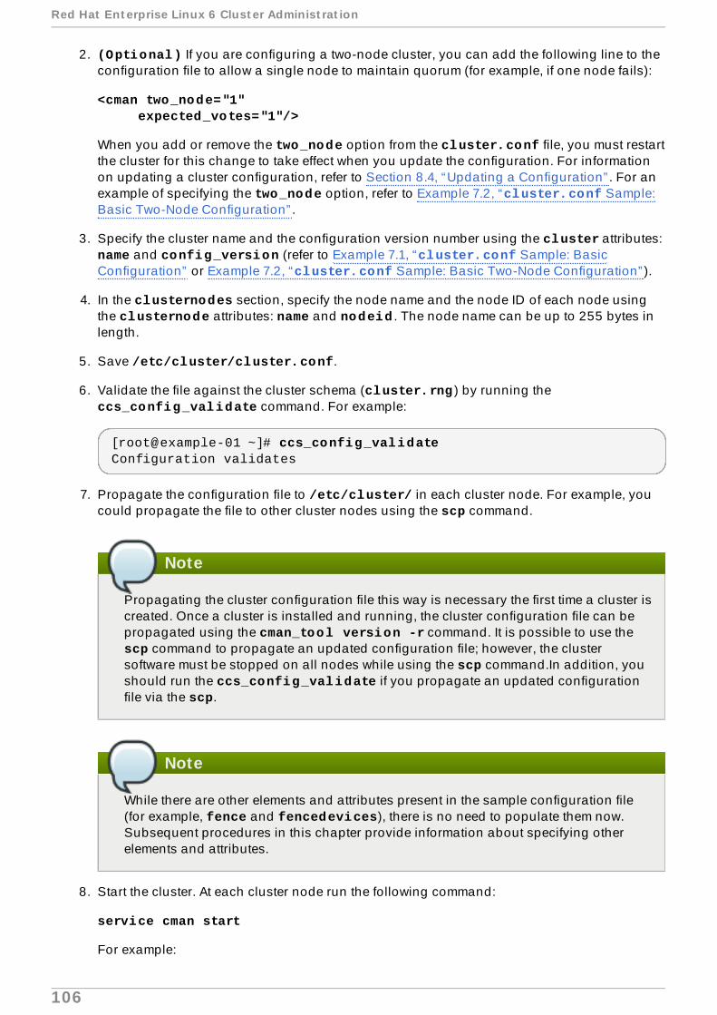
2. (Optional) If you are configuring a two-node cluster, you can add the following line to theconfiguration file to allow a single node to maintain quorum (for example, if one node fails):
<cman two_node="1" expected_votes="1"/>
When you add or remove the two_node option from the cluster.conf file, you must restartthe cluster for this change to take effect when you update the configuration. For informationon updating a cluster configuration, refer to Section 8.4, “Updating a Configuration” . For anexample of specifying the two_node option, refer to Example 7.2, “cluster.conf Sample:Basic Two-Node Configuration” .
3. Specify the cluster name and the configuration version number using the cluster attributes: name and config_version (refer to Example 7.1, “cluster.conf Sample: BasicConfiguration” or Example 7.2, “cluster.conf Sample: Basic Two-Node Configuration” ).
4. In the clusternodes section, specify the node name and the node ID of each node usingthe clusternode attributes: name and nodeid . The node name can be up to 255 bytes inlength.
5. Save /etc/cluster/cluster.conf.
6. Validate the file against the cluster schema (cluster.rng ) by running the ccs_config_validate command. For example:
[root@example-01 ~]# ccs_config_validate Configuration validates
7. Propagate the configuration file to /etc/cluster/ in each cluster node. For example, youcould propagate the file to other cluster nodes using the scp command.
Note
Propagating the cluster configuration file this way is necessary the first time a cluster iscreated. Once a cluster is installed and running, the cluster configuration file can bepropagated using the cman_tool version -r command. It is possible to use the scp command to propagate an updated configuration file; however, the clustersoftware must be stopped on all nodes while using the scp command.In addition, youshould run the ccs_config_validate if you propagate an updated configurationfile via the scp.
Note
While there are other elements and attributes present in the sample configuration file(for example, fence and fencedevices), there is no need to populate them now.Subsequent procedures in this chapter provide information about specifying otherelements and attributes.
8. Start the cluster. At each cluster node run the following command:
service cman start
For example:
Red Hat Ent erprise Linux 6 Clust er Administ rat ion
106

[root@example-01 ~]# service cman startStarting cluster: Checking Network Manager... [ OK ] Global setup... [ OK ] Loading kernel modules... [ OK ] Mounting configfs... [ OK ] Starting cman... [ OK ] Waiting for quorum... [ OK ] Starting fenced... [ OK ] Starting dlm_controld... [ OK ] Starting gfs_controld... [ OK ] Unfencing self... [ OK ] Joining fence domain... [ OK ]
9. At any cluster node, run cman_tool nodes to verify that the nodes are functioning asmembers in the cluster (signified as "M" in the status column, "Sts"). For example:
[root@example-01 ~]# cman_tool nodesNode Sts Inc Joined Name 1 M 548 2010-09-28 10:52:21 node-01.example.com 2 M 548 2010-09-28 10:52:21 node-02.example.com 3 M 544 2010-09-28 10:52:21 node-03.example.com
10. If the cluster is running, proceed to Section 7.3, “Configuring Fencing” .
Basic Configuration Examples
Example 7.1, “cluster.conf Sample: Basic Configuration” and Example 7.2, “cluster.confSample: Basic Two-Node Configuration” (for a two-node cluster) each provide a very basic samplecluster configuration file as a starting point. Subsequent procedures in this chapter provideinformation about configuring fencing and HA services.
Example 7.1. cluster.conf Sample: Basic Conf igurat ion
<cluster name="mycluster" config_version="2"> <clusternodes> <clusternode name="node-01.example.com" nodeid="1"> <fence> </fence> </clusternode> <clusternode name="node-02.example.com" nodeid="2"> <fence> </fence> </clusternode> <clusternode name="node-03.example.com" nodeid="3"> <fence> </fence> </clusternode> </clusternodes> <fencedevices>
Basic Configurat ion Examples
107

</fencedevices> <rm> </rm></cluster>
Example 7.2. cluster.conf Sample: Basic Two-Node Conf igurat ion
<cluster name="mycluster" config_version="2"> <cman two_node="1" expected_votes="1"/> <clusternodes> <clusternode name="node-01.example.com" nodeid="1"> <fence> </fence> </clusternode> <clusternode name="node-02.example.com" nodeid="2"> <fence> </fence> </clusternode> </clusternodes> <fencedevices> </fencedevices> <rm> </rm></cluster>
The consensus Value for totem in a Two-Node Cluster
When you create a two-node cluster and you do not intend to add additional nodes to the cluster at alater time, then you should omit the consensus value in the totem tag in the cluster.conf file sothat the consensus value is calculated automatically. When the consensus value is calculatedautomatically, the following rules are used:
If there are two nodes or fewer, the consensus value will be (token * 0.2), with a ceiling of 2000msec and a floor of 200 msec.
If there are three or more nodes, the consensus value will be (token + 2000 msec)
If you let the cman utility configure your consensus timeout in this fashion, then moving at a later timefrom two to three (or more) nodes will require a cluster restart, since the consensus timeout will needto change to the larger value based on the token timeout.
If you are configuring a two-node cluster and intend to upgrade in the future to more than two nodes,you can override the consensus timeout so that a cluster restart is not required when moving fromtwo to three (or more) nodes. This can be done in the cluster.conf as follows:
<totem token="X" consensus="X + 2000" />
Note that the configuration parser does not calculate X + 2000 automatically. An integer value mustbe used rather than an equation.
Red Hat Ent erprise Linux 6 Clust er Administ rat ion
108

The advantage of using the optimized consensus timeout for two-node clusters is that overall failovertime is reduced for the two-node case, since consensus is not a function of the token timeout.
Note that for two-node autodetection in cman, the number of physical nodes is what matters and notthe presence of the two_node=1 directive in the cluster.conf file.
7.3. Configuring Fencing
Configuring fencing consists of (a) specifying one or more fence devices in a cluster and (b)specifying one or more fence methods for each node (using a fence device or fence devicesspecified).
Note
It is recommended that you configure multiple fencing mechanisms for each node. A fencingdevice can fail due to network split, a power outage, or a problem in the fencing device itself.Configuring multiple fencing mechanisms can reduce the likelihood that the failure of afencing device will have fatal results.
Based on the type of fence devices and fence methods required for your configuration, configure cluster.conf as follows:
1. In the fencedevices section, specify each fence device, using a fencedevice elementand fence-device dependent attributes. Example 7.3, “APC Fence Device Added to cluster.conf ” shows an example of a configuration file with an APC fence device addedto it.
2. At the clusternodes section, within the fence element of each clusternode section,specify each fence method of the node. Specify the fence method name, using the methodattribute, name. Specify the fence device for each fence method, using the device elementand its attributes, name and fence-device-specific parameters. Example 7.4, “Fence MethodsAdded to cluster.conf ” shows an example of a fence method with one fence device foreach node in the cluster.
3. For non-power fence methods (that is, SAN/storage fencing), at the clusternodes section,add an unfence section. This ensures that a fenced node is not re-enabled until the nodehas been rebooted. When you configure a device that requires unfencing, the cluster mustfirst be stopped and the full configuration including devices and unfencing must be addedbefore the cluster is started. For more information about unfencing a node, refer to the fence_node(8) man page.
The unfence section does not contain method sections like the fence section does. Itcontains device references directly, which mirror the corresponding device sections for fence, with the notable addition of the explicit action (action) of "on" or "enable". Thesame fencedevice is referenced by both fence and unfence device lines, and the sameper-node arguments should be repeated.
Specifying the action attribute as "on" or "enable" enables the node when rebooted.Example 7.4, “Fence Methods Added to cluster.conf ” and Example 7.5, “cluster.conf:Multiple Fence Methods per Node” include examples of the unfence elements and attributed.
For more information about unfence refer to the fence_node man page.
4. Update the config_version attribute by incrementing its value (for example, changingfrom config_version="2" to config_version="3">).
T he consensus Value for t ot em in a T wo- Node Clust er
109

5. Save /etc/cluster/cluster.conf.
6. (Optional) Validate the updated file against the cluster schema (cluster.rng ) byrunning the ccs_config_validate command. For example:
[root@example-01 ~]# ccs_config_validate Configuration validates
7. Run the cman_tool version -r command to propagate the configuration to the rest of thecluster nodes. This will also run additional validation. It is necessary that ricci be runningin each cluster node to be able to propagate updated cluster configuration information.
8. Verify that the updated configuration file has been propagated.
9. Proceed to Section 7.4, “Configuring Failover Domains” .
If required, you can configure complex configurations with multiple fence methods per node and withmultiple fence devices per fence method. When specifying multiple fence methods per node, if fencingfails using the first method, fenced , the fence daemon, tries the next method, and continues to cyclethrough methods until one succeeds.
Sometimes, fencing a node requires disabling two I/O paths or two power ports. This is done byspecifying two or more devices within a fence method. fenced runs the fence agent once for eachfence-device line; all must succeed for fencing to be considered successful.
More complex configurations are shown in the section called “Fencing Configuration Examples” .
You can find more information about configuring specific fence devices from a fence-device agentman page (for example, the man page for fence_apc). In addition, you can get more informationabout fencing parameters from Appendix A, Fence Device Parameters, the fence agents in /usr/sbin/, the cluster schema at /usr/share/cluster/cluster.rng , and the annotatedschema at /usr/share/doc/cman-X.Y.ZZ/cluster_conf.html (for example, /usr/share/doc/cman-3.0.12/cluster_conf.html ).
Note
As of Red Hat Enterprise Linux Release 6.4, you can test the fence configuration for each nodein a cluster with the fence_check utility. For information on this utility, see the fence_check(8) man page.
Fencing Configuration Examples
The following examples show a simple configuration with one fence method per node and one fencedevice per fence method:
Example 7.3, “APC Fence Device Added to cluster.conf ”
Example 7.4, “Fence Methods Added to cluster.conf ”
The following examples show more complex configurations:
Example 7.5, “cluster.conf: Multiple Fence Methods per Node”
Example 7.6, “cluster.conf: Fencing, Multipath Multiple Ports”
Red Hat Ent erprise Linux 6 Clust er Administ rat ion
110

Example 7.7, “cluster.conf: Fencing Nodes with Dual Power Supplies”
Note
The examples in this section are not exhaustive; that is, there may be other ways to configurefencing depending on your requirements.
Example 7.3. APC Fence Device Added to cluster.conf
<cluster name="mycluster" config_version="3"> <clusternodes> <clusternode name="node-01.example.com" nodeid="1"> <fence> </fence> </clusternode> <clusternode name="node-02.example.com" nodeid="2"> <fence> </fence> </clusternode> <clusternode name="node-03.example.com" nodeid="3"> <fence> </fence> </clusternode> </clusternodes> <fencedevices> <fencedevice agent="fence_apc" ipaddr="apc_ip_example" login="login_example" name="apc" passwd="password_example"/> </fencedevices> <rm> </rm></cluster>
In this example, a fence device (fencedevice) has been added to the fencedevices element,specifying the fence agent (agent) as fence_apc, the IP address (ipaddr) as apc_ip_example, the login (login) as login_example, the name of the fence device (name)as apc, and the password (passwd ) as password_example.
Example 7.4 . Fence Methods Added to cluster.conf
<cluster name="mycluster" config_version="3"> <clusternodes> <clusternode name="node-01.example.com" nodeid="1"> <fence> <method name="APC"> <device name="apc" port="1"/> </method> </fence> </clusternode> <clusternode name="node-02.example.com" nodeid="2">
Fencing Configurat ion Examples
111

<fence> <method name="APC"> <device name="apc" port="2"/> </method> </fence> </clusternode> <clusternode name="node-03.example.com" nodeid="3"> <fence> <method name="APC"> <device name="apc" port="3"/> </method> </fence> </clusternode> </clusternodes> <fencedevices> <fencedevice agent="fence_apc" ipaddr="apc_ip_example" login="login_example" name="apc" passwd="password_example"/> </fencedevices> <rm> </rm></cluster>
In this example, a fence method (method ) has been added to each node. The name of the fencemethod (name) for each node is APC . The device (device) for the fence method in each nodespecifies the name (name) as apc and a unique APC switch power port number (port) for eachnode. For example, the port number for node-01.example.com is 1 (port="1"). The device namefor each node (device name="apc") points to the fence device by the name (name) of apc inthis line of the fencedevices element: fencedevice agent="fence_apc" ipaddr="apc_ip_example" login="login_example" name="apc" passwd="password_example".
Example 7.5. cluster.conf: Mult ip le Fence Methods per Node
<cluster name="mycluster" config_version="3"> <clusternodes> <clusternode name="node-01.example.com" nodeid="1"> <fence> <method name="APC"> <device name="apc" port="1"/> </method> <method name="SAN"> <device name="sanswitch1" port="11"/> </method> </fence> <unfence> <device name="sanswitch1" port="11" action="on"/> </unfence> </clusternode> <clusternode name="node-02.example.com" nodeid="2"> <fence> <method name="APC"> <device name="apc" port="2"/> </method> <method name="SAN">
Red Hat Ent erprise Linux 6 Clust er Administ rat ion
112

<device name="sanswitch1" port="12"/> </method> </fence> <unfence> <device name="sanswitch1" port="12" action="on"/> </unfence> </clusternode> <clusternode name="node-03.example.com" nodeid="3"> <fence> <method name="APC"> <device name="apc" port="3"/> </method> <method name="SAN"> <device name="sanswitch1" port="13"/> </method> </fence> <unfence> <device name="sanswitch1" port="13" action="on"/> </unfence> </clusternode> </clusternodes> <fencedevices> <fencedevice agent="fence_apc" ipaddr="apc_ip_example" login="login_example" name="apc" passwd="password_example"/> <fencedevice agent="fence_sanbox2" ipaddr="san_ip_example"login="login_example" name="sanswitch1" passwd="password_example"/> </fencedevices> <rm> </rm></cluster>
Example 7.6 . cluster.conf: Fencing, Mult ipath Mult ip le Ports
<cluster name="mycluster" config_version="3"> <clusternodes> <clusternode name="node-01.example.com" nodeid="1"> <fence> <method name="SAN-multi"> <device name="sanswitch1" port="11"/> <device name="sanswitch2" port="11"/> </method> </fence> <unfence> <device name="sanswitch1" port="11" action="on"/> <device name="sanswitch2" port="11" action="on"/> </unfence> </clusternode> <clusternode name="node-02.example.com" nodeid="2"> <fence> <method name="SAN-multi"> <device name="sanswitch1" port="12"/> <device name="sanswitch2" port="12"/> </method>
Fencing Configurat ion Examples
113

</fence> <unfence> <device name="sanswitch1" port="12" action="on"/> <device name="sanswitch2" port="12" action="on"/> </unfence> </clusternode> <clusternode name="node-03.example.com" nodeid="3"> <fence> <method name="SAN-multi"> <device name="sanswitch1" port="13"/> <device name="sanswitch2" port="13"/> </method> </fence> <unfence> <device name="sanswitch1" port="13" action="on"/> <device name="sanswitch2" port="13" action="on"/> </unfence> </clusternode> </clusternodes> <fencedevices> <fencedevice agent="fence_sanbox2" ipaddr="san_ip_example"login="login_example" name="sanswitch1" passwd="password_example"/> <fencedevice agent="fence_sanbox2" ipaddr="san_ip_example"login="login_example" name="sanswitch2" passwd="password_example"/> </fencedevices> <rm> </rm></cluster>
Example 7.7. cluster.conf: Fencing Nodes with Dual Power Supplies
<cluster name="mycluster" config_version="3"> <clusternodes> <clusternode name="node-01.example.com" nodeid="1"> <fence> <method name="APC-dual"> <device name="apc1" port="1"action="off"/> <device name="apc2" port="1"action="off"/> <device name="apc1" port="1"action="on"/> <device name="apc2" port="1"action="on"/> </method> </fence> </clusternode> <clusternode name="node-02.example.com" nodeid="2"> <fence> <method name="APC-dual"> <device name="apc1" port="2"action="off"/> <device name="apc2" port="2"action="off"/> <device name="apc1" port="2"action="on"/> <device name="apc2" port="2"action="on"/> </method> </fence> </clusternode>
Red Hat Ent erprise Linux 6 Clust er Administ rat ion
114

<clusternode name="node-03.example.com" nodeid="3"> <fence> <method name="APC-dual"> <device name="apc1" port="3"action="off"/> <device name="apc2" port="3"action="off"/> <device name="apc1" port="3"action="on"/> <device name="apc2" port="3"action="on"/> </method> </fence> </clusternode> </clusternodes> <fencedevices> <fencedevice agent="fence_apc" ipaddr="apc_ip_example" login="login_example" name="apc1" passwd="password_example"/> <fencedevice agent="fence_apc" ipaddr="apc_ip_example" login="login_example" name="apc2" passwd="password_example"/> </fencedevices> <rm> </rm></cluster>
When using power switches to fence nodes with dual power supplies, the agents must be told toturn off both power ports before restoring power to either port. The default off-on behavior of theagent could result in the power never being fully disabled to the node.
7.4 . Configuring Failover Domains
A failover domain is a named subset of cluster nodes that are eligible to run a cluster service in theevent of a node failure. A failover domain can have the following characteristics:
Unrestricted — Allows you to specify that a subset of members are preferred, but that a clusterservice assigned to this domain can run on any available member.
Restricted — Allows you to restrict the members that can run a particular cluster service. If none ofthe members in a restricted failover domain are available, the cluster service cannot be started(either manually or by the cluster software).
Unordered — When a cluster service is assigned to an unordered failover domain, the member onwhich the cluster service runs is chosen from the available failover domain members with nopriority ordering.
Ordered — Allows you to specify a preference order among the members of a failover domain.Ordered failover domains select the node with the lowest priority number first. That is, the node ina failover domain with a priority number of "1" specifies the highest priority, and therefore is themost preferred node in a failover domain. After that node, the next preferred node would be thenode with the next highest priority number, and so on.
Failback — Allows you to specify whether a service in the failover domain should fail back to thenode that it was originally running on before that node failed. Configuring this characteristic isuseful in circumstances where a node repeatedly fails and is part of an ordered failover domain.In that circumstance, if a node is the preferred node in a failover domain, it is possible for aservice to fail over and fail back repeatedly between the preferred node and another node,causing severe impact on performance.
Fencing Configurat ion Examples
115

Note
The failback characteristic is applicable only if ordered failover is configured.
Note
Changing a failover domain configuration has no effect on currently running services.
Note
Failover domains are not required for operation.
By default, failover domains are unrestricted and unordered.
In a cluster with several members, using a restricted failover domain can minimize the work to set upthe cluster to run a cluster service (such as httpd ), which requires you to set up the configurationidentically on all members that run the cluster service. Instead of setting up the entire cluster to runthe cluster service, you can set up only the members in the restricted failover domain that youassociate with the cluster service.
Note
To configure a preferred member, you can create an unrestricted failover domain comprisingonly one cluster member. Doing that causes a cluster service to run on that cluster memberprimarily (the preferred member), but allows the cluster service to fail over to any of the othermembers.
To configure a failover domain, use the following procedures:
1. Open /etc/cluster/cluster.conf at any node in the cluster.
2. Add the following skeleton section within the rm element for each failover domain to be used:
<failoverdomains> <failoverdomain name="" nofailback="" ordered="" restricted=""> <failoverdomainnode name="" priority=""/> <failoverdomainnode name="" priority=""/> <failoverdomainnode name="" priority=""/> </failoverdomain> </failoverdomains>
Red Hat Ent erprise Linux 6 Clust er Administ rat ion
116

Note
The number of failoverdomainnode attributes depends on the number of nodes inthe failover domain. The skeleton failoverdomain section in preceding text showsthree failoverdomainnode elements (with no node names specified), signifyingthat there are three nodes in the failover domain.
3. In the failoverdomain section, provide the values for the elements and attributes. Fordescriptions of the elements and attributes, refer to the failoverdomain section of the annotatedcluster schema. The annotated cluster schema is available at /usr/share/doc/cman-X.Y.ZZ/cluster_conf.html (for example /usr/share/doc/cman-3.0.12/cluster_conf.html ) in any of the cluster nodes. For an example of a failoverdomains section, refer to Example 7.8, “A Failover Domain Added to cluster.conf ” .
4. Update the config_version attribute by incrementing its value (for example, changingfrom config_version="2" to config_version="3">).
5. Save /etc/cluster/cluster.conf.
6. (Optional) Validate the file against the cluster schema (cluster.rng ) by running the ccs_config_validate command. For example:
[root@example-01 ~]# ccs_config_validate Configuration validates
7. Run the cman_tool version -r command to propagate the configuration to the rest of thecluster nodes.
8. Proceed to Section 7.5, “Configuring HA Services” .
Example 7.8, “A Failover Domain Added to cluster.conf ” shows an example of a configurationwith an ordered, unrestricted failover domain.
Example 7.8. A Failover Domain Added to cluster.conf
<cluster name="mycluster" config_version="3"> <clusternodes> <clusternode name="node-01.example.com" nodeid="1"> <fence> <method name="APC"> <device name="apc" port="1"/> </method> </fence> </clusternode> <clusternode name="node-02.example.com" nodeid="2"> <fence> <method name="APC"> <device name="apc" port="2"/> </method> </fence> </clusternode> <clusternode name="node-03.example.com" nodeid="3">
Fencing Configurat ion Examples
117

<fence> <method name="APC"> <device name="apc" port="3"/> </method> </fence> </clusternode> </clusternodes> <fencedevices> <fencedevice agent="fence_apc" ipaddr="apc_ip_example" login="login_example" name="apc" passwd="password_example"/> </fencedevices> <rm> <failoverdomains> <failoverdomain name="example_pri" nofailback="0" ordered="1" restricted="0"> <failoverdomainnode name="node-01.example.com" priority="1"/> <failoverdomainnode name="node-02.example.com" priority="2"/> <failoverdomainnode name="node-03.example.com" priority="3"/> </failoverdomain> </failoverdomains> </rm></cluster>
The failoverdomains section contains a failoverdomain section for each failover domainin the cluster. This example has one failover domain. In the failoverdomain line, the name(name) is specified as example_pri . In addition, it specifies no failback (failback="0"), thatfailover is ordered (ordered="1"), and that the failover domain is unrestricted(restricted="0").
7.5. Configuring HA Services
Configuring HA (High Availability) services consists of configuring resources and assigning them toservices.
The following sections describe how to edit /etc/cluster/cluster.conf to add resources andservices.
Section 7.5.1, “Adding Cluster Resources”
Section 7.5.2, “Adding a Cluster Service to the Cluster”
Important
There can be a wide range of configurations possible with High Availability resources andservices. For a better understanding about resource parameters and resource behavior, referto Appendix B, HA Resource Parameters and Appendix C, HA Resource Behavior. For optimalperformance and to ensure that your configuration can be supported, contact an authorizedRed Hat support representative.
Red Hat Ent erprise Linux 6 Clust er Administ rat ion
118

7.5.1. Adding Cluster Resources
You can configure two types of resources:
Global — Resources that are available to any service in the cluster. These are configured in the resources section of the configuration file (within the rm element).
Service-specific — Resources that are available to only one service. These are configured in eachservice section of the configuration file (within the rm element).
This section describes how to add a global resource. For procedures about configuring service-specific resources, refer to Section 7.5.2, “Adding a Cluster Service to the Cluster” .
To add a global cluster resource, follow the steps in this section.
1. Open /etc/cluster/cluster.conf at any node in the cluster.
2. Add a resources section within the rm element. For example:
<rm> <resources>
</resources> </rm>
3. Populate it with resources according to the services you want to create. For example, here areresources that are to be used in an Apache service. They consist of a file system (fs)resource, an IP (ip) resource, and an Apache (apache) resource.
<rm> <resources> <fs name="web_fs" device="/dev/sdd2" mountpoint="/var/www" fstype="ext3"/> <ip address="127.143.131.100" monitor_link="yes" sleeptime="10"/> <apache config_file="conf/httpd.conf" name="example_server" server_root="/etc/httpd" shutdown_wait="0"/> </resources> </rm>
Example 7.9, “cluster.conf File with Resources Added ” shows an example of a cluster.conf file with the resources section added.
4. Update the config_version attribute by incrementing its value (for example, changingfrom config_version="2" to config_version="3").
5. Save /etc/cluster/cluster.conf.
6. (Optional) Validate the file against the cluster schema (cluster.rng ) by running the ccs_config_validate command. For example:
[root@example-01 ~]# ccs_config_validate Configuration validates
Fencing Configurat ion Examples
119

7. Run the cman_tool version -r command to propagate the configuration to the rest of thecluster nodes.
8. Verify that the updated configuration file has been propagated.
9. Proceed to Section 7.5.2, “Adding a Cluster Service to the Cluster” .
Example 7.9 . cluster.conf File with Resources Added
<cluster name="mycluster" config_version="3"> <clusternodes> <clusternode name="node-01.example.com" nodeid="1"> <fence> <method name="APC"> <device name="apc" port="1"/> </method> </fence> </clusternode> <clusternode name="node-02.example.com" nodeid="2"> <fence> <method name="APC"> <device name="apc" port="2"/> </method> </fence> </clusternode> <clusternode name="node-03.example.com" nodeid="3"> <fence> <method name="APC"> <device name="apc" port="3"/> </method> </fence> </clusternode> </clusternodes> <fencedevices> <fencedevice agent="fence_apc" ipaddr="apc_ip_example" login="login_example" name="apc" passwd="password_example"/> </fencedevices> <rm> <failoverdomains> <failoverdomain name="example_pri" nofailback="0" ordered="1" restricted="0"> <failoverdomainnode name="node-01.example.com" priority="1"/> <failoverdomainnode name="node-02.example.com" priority="2"/> <failoverdomainnode name="node-03.example.com" priority="3"/> </failoverdomain> </failoverdomains> <resources> <fs name="web_fs" device="/dev/sdd2" mountpoint="/var/www" fstype="ext3"/> <ip address="127.143.131.100" monitor_link="yes" sleeptime="10"/>
Red Hat Ent erprise Linux 6 Clust er Administ rat ion
120

<apache config_file="conf/httpd.conf" name="example_server" server_root="/etc/httpd" shutdown_wait="0"/> </resources>
</rm></cluster>
7.5.2. Adding a Cluster Service to the Cluster
To add a cluster service to the cluster, follow the steps in this section.
Note
The examples provided in this section show a cluster service in which all of the resources areat the same level. For information on defining a service in which there is a dependency chainin a resource hierarchy, as well as the rules that govern the behavior of parent and childresources, see Appendix C, HA Resource Behavior.
1. Open /etc/cluster/cluster.conf at any node in the cluster.
2. Add a service section within the rm element for each service. For example:
<rm> <service autostart="1" domain="" exclusive="0" name="" recovery="restart">
</service> </rm>
3. Configure the following parameters (attributes) in the service element:
autostart — Specifies whether to autostart the service when the cluster starts. Use '1' toenable and '0' to disable; the default is enabled.
domain — Specifies a failover domain (if required).
exclusive — Specifies a policy wherein the service only runs on nodes that have noother services running on them.
recovery — Specifies a recovery policy for the service. The options are to relocate,restart, disable, or restart-disable the service.
4. Depending on the type of resources you want to use, populate the service with global orservice-specific resources
For example, here is an Apache service that uses global resources:
<rm> <resources> <fs name="web_fs" device="/dev/sdd2" mountpoint="/var/www" fstype="ext3"/>
Fencing Configurat ion Examples
121

<ip address="127.143.131.100" monitor_link="yes" sleeptime="10"/> <apache config_file="conf/httpd.conf" name="example_server" server_root="/etc/httpd" shutdown_wait="0"/> </resources> <service autostart="1" domain="example_pri" exclusive="0" name="example_apache" recovery="relocate"> <fs ref="web_fs"/> <ip ref="127.143.131.100"/> <apache ref="example_server"/> </service> </rm>
For example, here is an Apache service that uses service-specific resources:
<rm> <service autostart="0" domain="example_pri" exclusive="0" name="example_apache2" recovery="relocate"> <fs name="web_fs2" device="/dev/sdd3" mountpoint="/var/www2" fstype="ext3"/> <ip address="127.143.131.101" monitor_link="yes" sleeptime="10"/> <apache config_file="conf/httpd.conf" name="example_server2" server_root="/etc/httpd" shutdown_wait="0"/> </service> </rm>
Example 7.10, “cluster.conf with Services Added: One Using Global Resources and OneUsing Service-Specific Resources ” shows an example of a cluster.conf file with twoservices:
example_apache — This service uses global resources web_fs, 127.143.131.100 ,and example_server.
example_apache2 — This service uses service-specific resources web_fs2, 127.143.131.101, and example_server2.
5. Update the config_version attribute by incrementing its value (for example, changingfrom config_version="2" to config_version="3">).
6. Save /etc/cluster/cluster.conf.
7. (Optional) Validate the updated file against the cluster schema (cluster.rng ) byrunning the ccs_config_validate command. For example:
[root@example-01 ~]# ccs_config_validate Configuration validates
8. Run the cman_tool version -r command to propagate the configuration to the rest of thecluster nodes.
9. Verify that the updated configuration file has been propagated.
10. Proceed to Section 7.9, “Verifying a Configuration” .
Red Hat Ent erprise Linux 6 Clust er Administ rat ion
122

Example 7.10. cluster.conf with Services Added: One Using G lobal Resources andOne Using Service-Specif ic Resources
<cluster name="mycluster" config_version="3"> <clusternodes> <clusternode name="node-01.example.com" nodeid="1"> <fence> <method name="APC"> <device name="apc" port="1"/> </method> </fence> </clusternode> <clusternode name="node-02.example.com" nodeid="2"> <fence> <method name="APC"> <device name="apc" port="2"/> </method> </fence> </clusternode> <clusternode name="node-03.example.com" nodeid="3"> <fence> <method name="APC"> <device name="apc" port="3"/> </method> </fence> </clusternode> </clusternodes> <fencedevices> <fencedevice agent="fence_apc" ipaddr="apc_ip_example" login="login_example" name="apc" passwd="password_example"/> </fencedevices> <rm> <failoverdomains> <failoverdomain name="example_pri" nofailback="0" ordered="1" restricted="0"> <failoverdomainnode name="node-01.example.com" priority="1"/> <failoverdomainnode name="node-02.example.com" priority="2"/> <failoverdomainnode name="node-03.example.com" priority="3"/> </failoverdomain> </failoverdomains> <resources> <fs name="web_fs" device="/dev/sdd2" mountpoint="/var/www" fstype="ext3"/> <ip address="127.143.131.100" monitor_link="yes" sleeptime="10"/> <apache config_file="conf/httpd.conf" name="example_server" server_root="/etc/httpd" shutdown_wait="0"/> </resources> <service autostart="1" domain="example_pri" exclusive="0" name="example_apache" recovery="relocate"> <fs ref="web_fs"/>
Fencing Configurat ion Examples
123
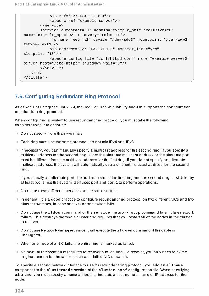
<ip ref="127.143.131.100"/> <apache ref="example_server"/> </service> <service autostart="0" domain="example_pri" exclusive="0" name="example_apache2" recovery="relocate"> <fs name="web_fs2" device="/dev/sdd3" mountpoint="/var/www2" fstype="ext3"/> <ip address="127.143.131.101" monitor_link="yes" sleeptime="10"/> <apache config_file="conf/httpd.conf" name="example_server2" server_root="/etc/httpd" shutdown_wait="0"/> </service> </rm></cluster>
7.6. Configuring Redundant Ring Protocol
As of Red Hat Enterprise Linux 6.4, the Red Hat High Availability Add-On supports the configurationof redundant ring protocol.
When configuring a system to use redundant ring protocol, you must take the followingconsiderations into account:
Do not specify more than two rings.
Each ring must use the same protocol; do not mix IPv4 and IPv6.
If necessary, you can manually specify a multicast address for the second ring. If you specify amulticast address for the second ring, either the alternate multicast address or the alternate portmust be different from the multicast address for the first ring. If you do not specify an alternatemulticast address, the system will automatically use a different multicast address for the secondring.
If you specify an alternate port, the port numbers of the first ring and the second ring must differ byat least two, since the system itself uses port and port-1 to perform operations.
Do not use two different interfaces on the same subnet.
In general, it is a good practice to configure redundant ring protocol on two different NICs and twodifferent switches, in case one NIC or one switch fails.
Do not use the ifdown command or the service network stop command to simulate networkfailure. This destroys the whole cluster and requires that you restart all of the nodes in the clusterto recover.
Do not use NetworkManager, since it will execute the ifdown command if the cable isunplugged.
When one node of a NIC fails, the entire ring is marked as failed.
No manual intervention is required to recover a failed ring. To recover, you only need to fix theoriginal reason for the failure, such as a failed NIC or switch.
To specify a second network interface to use for redundant ring protocol, you add an altnamecomponent to the clusternode section of the cluster.conf configuration file. When specifying altname, you must specify a name attribute to indicate a second host name or IP address for thenode.
Red Hat Ent erprise Linux 6 Clust er Administ rat ion
124

The following example specifies clusternet-node1-eth2 as the alternate name for cluster node clusternet-node1-eth1.
<cluster name="mycluster" config_version="3" > <logging debug="on"/> <clusternodes> <clusternode name="clusternet-node1-eth1" votes="1" nodeid="1"> <fence> <method name="single"> <device name="xvm" domain="clusternet-node1"/> </method> </fence> <altname name="clusternet-node1-eth2"/> </clusternode>
The altname section within the clusternode block is not position dependent. It can come beforeor after the fence section. Do not specify more than one altname component for a cluster node orthe system will fail to start.
Optionally, you can manually specify a multicast address, a port, and a TTL for the second ring byincluding an altmulticast component in the cman section of the cluster.conf configurationfile. The altmulticast component accepts an addr, a port, and a ttl parameter.
The following example shows the cman section of a cluster configuration file that sets a multicastaddress, port, and TTL for the second ring.
<cman> <multicast addr="239.192.99.73" port="666" ttl="2"/> <altmulticast addr="239.192.99.88" port="888" ttl="3"/></cman>
7.7. Configuring Debug Opt ions
You can enable debugging for all daemons in a cluster, or you can enable logging for specificcluster processing.
To enable debugging for all daemons, add the following to the /etc/cluster/cluster.conf. Bydefault, logging is directed to the /var/log/cluster/daemon.log file.
<cluster config_version="7" name="rh6cluster"> <logging debug="on"/> ... </cluster>
To enable debugging for individual cluster processes, add the following lines to the the /etc/cluster/cluster.conf file. Per-daemon logging configuration overrides the globalsettings.
<cluster config_version="7" name="rh6cluster"> ...
Fencing Configurat ion Examples
125

<logging> <!-- turning on per-subsystem debug logging --> <logging_daemon name="corosync" debug="on" /> <logging_daemon name="fenced" debug="on" /> <logging_daemon name="qdiskd" debug="on" /> <logging_daemon name="rgmanager" debug="on" /> <logging_daemon name="dlm_controld" debug="on" /> <logging_daemon name="gfs_controld" debug="on" /> </logging> ...</cluster>
For a list of the logging daemons for which you can enable logging as well as the additional loggingoptions you can configure for both global and per-daemon logging, refer to the cluster.conf(5)man page.
7.8. Configuring nfsexport and nfsserver Resources
This section describes the issues and considerations to take into account when configuring an nfsexport or an nfsserver resource.
The nfsexport resource agent works with NFSv2 and NFSv3 clients. When using nfsexport, youmust do the following:
Ensure that nfs and nfslock are enabled at boot.
Add RPCNFSDARGS="-N 4" to the /etc/sysconfig/nfs file on all cluster nodes. The "-N 4"option prevents NFSv4 clients from being able to connect to the server.
Add STATDARGS="-H /usr/sbin/clunfslock" to the /etc/sysconfig/nfs file on allcluster nodes.
Add nfslock="1" to the service component in the cluster.conf file.
Structure your service as follows:
<service nfslock="1" ... > <fs name="myfs" ... > <nfsexport name="exports"> <nfsclient ref="client1" /> <nfsclient ref="client2" /> ... </nfsexport> </fs> <ip address="10.1.1.2" /> ... </service>
The nfsserver resource agent works with NFSv3 and NFSv4 clients. When using nfsserver, youmust do the following:
Ensure that nfs and nfslock are disabled at boot
Ensure that nfslock="1" is not set for the service.
Structure your service as follows:
Red Hat Ent erprise Linux 6 Clust er Administ rat ion
126

<service ... > <fs name="myfs" ... > <nfsserver name="server"> <nfsclient ref="client1" /> <nfsclient ref="client2" /> <ip address="10.1.1.2" /> ... </nfserver> </fs> ... </service>
When configuring a system to use the nfsserver resource agent for use with NFSv3 and NFSv4,you must account for the following limitations:
Configure only one nfsserver resource per cluster. If you require more, you must use restrictedfailover domains to ensure that the two services in question can never start on the same host.
Do not reference a globally-configured nfsserver resource in more than one service.
Do not mix old-style NFS services with the new nfsserver in the same cluster. Older NFSservices required the NFS daemons to be running; nfsserver requires the daemons to bestopped when the service is started.
When using multiple file systems, you will be unable to use inheritance for the exports; thus reuseof nfsclient resources in services with multiple file systems is limited. You may, however,explicitly define target and path attributes for as many nfsclients as you like.
7.9. Verifying a Configurat ion
Once you have created your cluster configuration file, verify that it is running correctly by performingthe following steps:
1. At each node, restart the cluster software. That action ensures that any configurationadditions that are checked only at startup time are included in the running configuration. Youcan restart the cluster software by running service cman restart. For example:
[root@example-01 ~]# service cman restartStopping cluster: Leaving fence domain... [ OK ] Stopping gfs_controld... [ OK ] Stopping dlm_controld... [ OK ] Stopping fenced... [ OK ] Stopping cman... [ OK ] Waiting for corosync to shutdown: [ OK ] Unloading kernel modules... [ OK ] Unmounting configfs... [ OK ]Starting cluster: Checking Network Manager... [ OK ] Global setup... [ OK ] Loading kernel modules... [ OK ] Mounting configfs... [ OK ] Starting cman... [ OK ] Waiting for quorum... [ OK ]
Fencing Configurat ion Examples
127

Starting fenced... [ OK ] Starting dlm_controld... [ OK ] Starting gfs_controld... [ OK ] Unfencing self... [ OK ] Joining fence domain... [ OK ]
2. Run service clvmd start, if CLVM is being used to create clustered volumes. Forexample:
[root@example-01 ~]# service clvmd startActivating VGs: [ OK ]
3. Run service gfs2 start, if you are using Red Hat GFS2. For example:
[root@example-01 ~]# service gfs2 startMounting GFS2 filesystem (/mnt/gfsA): [ OK ]Mounting GFS2 filesystem (/mnt/gfsB): [ OK ]
4. Run service rgmanager start, if you using high-availability (HA) services. For example:
[root@example-01 ~]# service rgmanager startStarting Cluster Service Manager: [ OK ]
5. At any cluster node, run cman_tool nodes to verify that the nodes are functioning asmembers in the cluster (signified as "M" in the status column, "Sts"). For example:
[root@example-01 ~]# cman_tool nodesNode Sts Inc Joined Name 1 M 548 2010-09-28 10:52:21 node-01.example.com 2 M 548 2010-09-28 10:52:21 node-02.example.com 3 M 544 2010-09-28 10:52:21 node-03.example.com
6. At any node, using the clustat utility, verify that the HA services are running as expected. Inaddition, clustat displays status of the cluster nodes. For example:
[root@example-01 ~]#clustatCluster Status for mycluster @ Wed Nov 17 05:40:00 2010Member Status: Quorate
Member Name ID Status ------ ---- ---- ------ node-03.example.com 3 Online, rgmanager node-02.example.com 2 Online, rgmanager node-01.example.com 1 Online, Local, rgmanager
Service Name Owner (Last) State ------- ---- ----- ------ ----- service:example_apache node-01.example.com started service:example_apache2 (none) disabled
Red Hat Ent erprise Linux 6 Clust er Administ rat ion
128

7. If the cluster is running as expected, you are done with creating a configuration file. You canmanage the cluster with command-line tools described in Chapter 8, Managing Red Hat HighAvailability Add-On With Command Line Tools.
Fencing Configurat ion Examples
129

Chapter 8. Managing Red Hat High Availability Add-On WithCommand Line Tools
This chapter describes various administrative tasks for managing Red Hat High Availability Add-Onand consists of the following sections:
Section 8.1, “Starting and Stopping the Cluster Software”
Section 8.2, “Deleting or Adding a Node”
Section 8.3, “Managing High-Availability Services”
Section 8.4, “Updating a Configuration”
Important
Make sure that your deployment of Red Hat High Availability Add-On meets your needs andcan be supported. Consult with an authorized Red Hat representative to verify yourconfiguration prior to deployment. In addition, allow time for a configuration burn-in period totest failure modes.
Important
This chapter references commonly used cluster.conf elements and attributes. For acomprehensive list and description of cluster.conf elements and attributes, refer to thecluster schema at /usr/share/cluster/cluster.rng , and the annotated schema at /usr/share/doc/cman-X.Y.ZZ/cluster_conf.html (for example /usr/share/doc/cman-3.0.12/cluster_conf.html ).
Important
Certain procedure in this chapter call for using the cman_tool version -r command topropagate a cluster configuration throughout a cluster. Using that command requires that ricci is running.
Note
Procedures in this chapter, may include specific commands for some of the command-linetools listed in Appendix E, Command Line Tools Summary. For more information about allcommands and variables, refer to the man page for each command-line tool.
8.1. Start ing and Stopping the Cluster Software
Red Hat Ent erprise Linux 6 Clust er Administ rat ion
130
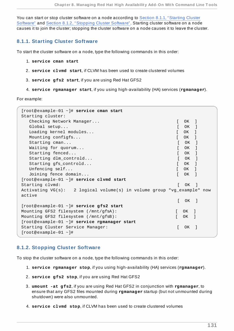
You can start or stop cluster software on a node according to Section 8.1.1, “Starting ClusterSoftware” and Section 8.1.2, “Stopping Cluster Software” . Starting cluster software on a nodecauses it to join the cluster; stopping the cluster software on a node causes it to leave the cluster.
8.1.1. Start ing Cluster Software
To start the cluster software on a node, type the following commands in this order:
1. service cman start
2. service clvmd start, if CLVM has been used to create clustered volumes
3. service gfs2 start, if you are using Red Hat GFS2
4. service rgmanager start, if you using high-availability (HA) services (rgmanager).
For example:
[root@example-01 ~]# service cman startStarting cluster: Checking Network Manager... [ OK ] Global setup... [ OK ] Loading kernel modules... [ OK ] Mounting configfs... [ OK ] Starting cman... [ OK ] Waiting for quorum... [ OK ] Starting fenced... [ OK ] Starting dlm_controld... [ OK ] Starting gfs_controld... [ OK ] Unfencing self... [ OK ] Joining fence domain... [ OK ][root@example-01 ~]# service clvmd startStarting clvmd: [ OK ]Activating VG(s): 2 logical volume(s) in volume group "vg_example" now active [ OK ][root@example-01 ~]# service gfs2 startMounting GFS2 filesystem (/mnt/gfsA): [ OK ]Mounting GFS2 filesystem (/mnt/gfsB): [ OK ][root@example-01 ~]# service rgmanager startStarting Cluster Service Manager: [ OK ][root@example-01 ~]#
8.1.2. Stopping Cluster Software
To stop the cluster software on a node, type the following commands in this order:
1. service rgmanager stop, if you using high-availability (HA) services (rgmanager).
2. service gfs2 stop, if you are using Red Hat GFS2
3. umount -at gfs2, if you are using Red Hat GFS2 in conjunction with rgmanager, toensure that any GFS2 files mounted during rgmanager startup (but not unmounted duringshutdown) were also unmounted.
4. service clvmd stop, if CLVM has been used to create clustered volumes
Chapt er 8 . Managing Red Hat High Availabilit y Add- On Wit h Command Line T ools
131

5. service cman stop
For example:
[root@example-01 ~]# service rgmanager stopStopping Cluster Service Manager: [ OK ][root@example-01 ~]# service gfs2 stopUnmounting GFS2 filesystem (/mnt/gfsA): [ OK ]Unmounting GFS2 filesystem (/mnt/gfsB): [ OK ][root@example-01 ~]# umount -at gfs2[root@example-01 ~]# service clvmd stopSignaling clvmd to exit [ OK ]clvmd terminated [ OK ][root@example-01 ~]# service cman stopStopping cluster: Leaving fence domain... [ OK ] Stopping gfs_controld... [ OK ] Stopping dlm_controld... [ OK ] Stopping fenced... [ OK ] Stopping cman... [ OK ] Waiting for corosync to shutdown: [ OK ] Unloading kernel modules... [ OK ] Unmounting configfs... [ OK ][root@example-01 ~]#
Note
Stopping cluster software on a node causes its HA services to fail over to another node. As analternative to that, consider relocating or migrating HA services to another node beforestopping cluster software. For information about managing HA services, refer to Section 8.3,“Managing High-Availability Services” .
8.2. Delet ing or Adding a Node
This section describes how to delete a node from a cluster and add a node to a cluster. You candelete a node from a cluster according to Section 8.2.1, “Deleting a Node from a Cluster” ; you canadd a node to a cluster according to Section 8.2.2, “Adding a Node to a Cluster” .
8.2.1. Delet ing a Node from a Cluster
Deleting a node from a cluster consists of shutting down the cluster software on the node to bedeleted and updating the cluster configuration to reflect the change.
Important
If deleting a node from the cluster causes a transition from greater than two nodes to twonodes, you must restart the cluster software at each node after updating the clusterconfiguration file.
To delete a node from a cluster, perform the following steps:
Red Hat Ent erprise Linux 6 Clust er Administ rat ion
132

1. At any node, use the clusvcadm utility to relocate, migrate, or stop each HA service runningon the node that is being deleted from the cluster. For information about using clusvcadm,refer to Section 8.3, “Managing High-Availability Services” .
2. At the node to be deleted from the cluster, stop the cluster software according to Section 8.1.2,“Stopping Cluster Software” . For example:
[root@example-01 ~]# service rgmanager stopStopping Cluster Service Manager: [ OK ][root@example-01 ~]# service gfs2 stopUnmounting GFS2 filesystem (/mnt/gfsA): [ OK ]Unmounting GFS2 filesystem (/mnt/gfsB): [ OK ][root@example-01 ~]# service clvmd stopSignaling clvmd to exit [ OK ]clvmd terminated [ OK ][root@example-01 ~]# service cman stopStopping cluster: Leaving fence domain... [ OK ] Stopping gfs_controld... [ OK ] Stopping dlm_controld... [ OK ] Stopping fenced... [ OK ] Stopping cman... [ OK ] Waiting for corosync to shutdown: [ OK ] Unloading kernel modules... [ OK ] Unmounting configfs... [ OK ][root@example-01 ~]#
3. At any node in the cluster, edit the /etc/cluster/cluster.conf to remove the clusternode section of the node that is to be deleted. For example, in Example 8.1, “Three-node Cluster Configuration” , if node-03.example.com is supposed to be removed, then deletethe clusternode section for that node. If removing a node (or nodes) causes the cluster tobe a two-node cluster, you can add the following line to the configuration file to allow a singlenode to maintain quorum (for example, if one node fails):
<cman two_node="1" expected_votes="1"/>
Refer to Section 8.2.3, “Examples of Three-Node and Two-Node Configurations” forcomparison between a three-node and a two-node configuration.
4. Update the config_version attribute by incrementing its value (for example, changingfrom config_version="2" to config_version="3">).
5. Save /etc/cluster/cluster.conf.
6. (Optional) Validate the updated file against the cluster schema (cluster.rng ) byrunning the ccs_config_validate command. For example:
[root@example-01 ~]# ccs_config_validate Configuration validates
7. Run the cman_tool version -r command to propagate the configuration to the rest of thecluster nodes.
8. Verify that the updated configuration file has been propagated.
Chapt er 8 . Managing Red Hat High Availabilit y Add- On Wit h Command Line T ools
133

9. If the node count of the cluster has transitioned from greater than two nodes to two nodes,you must restart the cluster software as follows:
a. At each node, stop the cluster software according to Section 8.1.2, “Stopping ClusterSoftware” . For example:
[root@example-01 ~]# service rgmanager stopStopping Cluster Service Manager: [ OK ][root@example-01 ~]# service gfs2 stopUnmounting GFS2 filesystem (/mnt/gfsA): [ OK ]Unmounting GFS2 filesystem (/mnt/gfsB): [ OK ][root@example-01 ~]# service clvmd stopSignaling clvmd to exit [ OK ]clvmd terminated [ OK ][root@example-01 ~]# service cman stopStopping cluster: Leaving fence domain... [ OK ] Stopping gfs_controld... [ OK ] Stopping dlm_controld... [ OK ] Stopping fenced... [ OK ] Stopping cman... [ OK ] Waiting for corosync to shutdown: [ OK ] Unloading kernel modules... [ OK ] Unmounting configfs... [ OK ][root@example-01 ~]#
b. At each node, start the cluster software according to Section 8.1.1, “Starting ClusterSoftware” . For example:
[root@example-01 ~]# service cman startStarting cluster: Checking Network Manager... [ OK ] Global setup... [ OK ] Loading kernel modules... [ OK ] Mounting configfs... [ OK ] Starting cman... [ OK ] Waiting for quorum... [ OK ]
Red Hat Ent erprise Linux 6 Clust er Administ rat ion
134
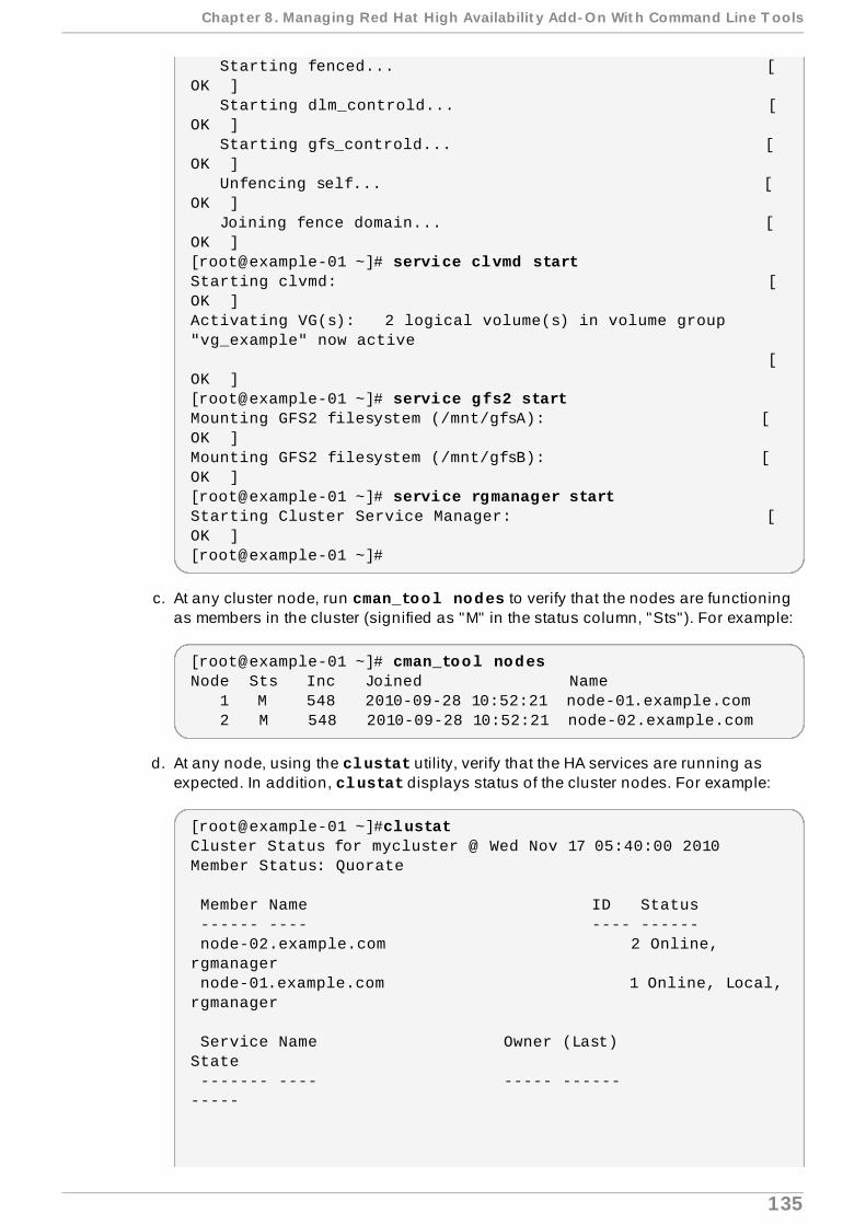
Starting fenced... [ OK ] Starting dlm_controld... [ OK ] Starting gfs_controld... [ OK ] Unfencing self... [ OK ] Joining fence domain... [ OK ][root@example-01 ~]# service clvmd startStarting clvmd: [ OK ]Activating VG(s): 2 logical volume(s) in volume group "vg_example" now active [ OK ][root@example-01 ~]# service gfs2 startMounting GFS2 filesystem (/mnt/gfsA): [ OK ]Mounting GFS2 filesystem (/mnt/gfsB): [ OK ][root@example-01 ~]# service rgmanager startStarting Cluster Service Manager: [ OK ][root@example-01 ~]#
c. At any cluster node, run cman_tool nodes to verify that the nodes are functioningas members in the cluster (signified as "M" in the status column, "Sts"). For example:
[root@example-01 ~]# cman_tool nodesNode Sts Inc Joined Name 1 M 548 2010-09-28 10:52:21 node-01.example.com 2 M 548 2010-09-28 10:52:21 node-02.example.com
d. At any node, using the clustat utility, verify that the HA services are running asexpected. In addition, clustat displays status of the cluster nodes. For example:
[root@example-01 ~]#clustatCluster Status for mycluster @ Wed Nov 17 05:40:00 2010Member Status: Quorate
Member Name ID Status ------ ---- ---- ------ node-02.example.com 2 Online, rgmanager node-01.example.com 1 Online, Local, rgmanager
Service Name Owner (Last) State ------- ---- ----- ------ -----
Chapt er 8 . Managing Red Hat High Availabilit y Add- On Wit h Command Line T ools
135

service:example_apache node-01.example.com started service:example_apache2 (none) disabled
8.2.2. Adding a Node to a Cluster
Adding a node to a cluster consists of updating the cluster configuration, propagating the updatedconfiguration to the node to be added, and starting the cluster software on that node. To add a nodeto a cluster, perform the following steps:
1. At any node in the cluster, edit the /etc/cluster/cluster.conf to add a clusternodesection for the node that is to be added. For example, in Example 8.2, “Two-node ClusterConfiguration” , if node-03.example.com is supposed to be added, then add a clusternodesection for that node. If adding a node (or nodes) causes the cluster to transition from a two-node cluster to a cluster with three or more nodes, remove the following cman attributes from /etc/cluster/cluster.conf:
cman two_node="1"
expected_votes="1"
Refer to Section 8.2.3, “Examples of Three-Node and Two-Node Configurations” forcomparison between a three-node and a two-node configuration.
2. Update the config_version attribute by incrementing its value (for example, changingfrom config_version="2" to config_version="3">).
3. Save /etc/cluster/cluster.conf.
4. (Optional) Validate the updated file against the cluster schema (cluster.rng ) byrunning the ccs_config_validate command. For example:
[root@example-01 ~]# ccs_config_validate Configuration validates
5. Run the cman_tool version -r command to propagate the configuration to the rest of thecluster nodes.
6. Verify that the updated configuration file has been propagated.
7. Propagate the updated configuration file to /etc/cluster/ in each node to be added to thecluster. For example, use the scp command to send the updated configuration file to eachnode to be added to the cluster.
8. If the node count of the cluster has transitioned from two nodes to greater than two nodes,you must restart the cluster software in the existing cluster nodes as follows:
a. At each node, stop the cluster software according to Section 8.1.2, “Stopping ClusterSoftware” . For example:
[root@example-01 ~]# service rgmanager stopStopping Cluster Service Manager: [ OK ][root@example-01 ~]# service gfs2 stopUnmounting GFS2 filesystem (/mnt/gfsA): [ OK ]
Red Hat Ent erprise Linux 6 Clust er Administ rat ion
136

Unmounting GFS2 filesystem (/mnt/gfsB): [ OK ][root@example-01 ~]# service clvmd stopSignaling clvmd to exit [ OK ]clvmd terminated [ OK ][root@example-01 ~]# service cman stopStopping cluster: Leaving fence domain... [ OK ] Stopping gfs_controld... [ OK ] Stopping dlm_controld... [ OK ] Stopping fenced... [ OK ] Stopping cman... [ OK ] Waiting for corosync to shutdown: [ OK ] Unloading kernel modules... [ OK ] Unmounting configfs... [ OK ][root@example-01 ~]#
b. At each node, start the cluster software according to Section 8.1.1, “Starting ClusterSoftware” . For example:
[root@example-01 ~]# service cman startStarting cluster: Checking Network Manager... [ OK ] Global setup... [ OK ] Loading kernel modules... [ OK ] Mounting configfs... [ OK ] Starting cman... [ OK ] Waiting for quorum... [ OK ] Starting fenced... [ OK ] Starting dlm_controld... [ OK ] Starting gfs_controld... [ OK ] Unfencing self... [ OK ] Joining fence domain... [ OK ][root@example-01 ~]# service clvmd startStarting clvmd: [
Chapt er 8 . Managing Red Hat High Availabilit y Add- On Wit h Command Line T ools
137

OK ]Activating VG(s): 2 logical volume(s) in volume group "vg_example" now active [ OK ][root@example-01 ~]# service gfs2 startMounting GFS2 filesystem (/mnt/gfsA): [ OK ]Mounting GFS2 filesystem (/mnt/gfsB): [ OK ][root@example-01 ~]# service rgmanager startStarting Cluster Service Manager: [ OK ][root@example-01 ~]#
9. At each node to be added to the cluster, start the cluster software according to Section 8.1.1,“Starting Cluster Software” . For example:
[root@example-01 ~]# service cman startStarting cluster: Checking Network Manager... [ OK ] Global setup... [ OK ] Loading kernel modules... [ OK ] Mounting configfs... [ OK ] Starting cman... [ OK ] Waiting for quorum... [ OK ] Starting fenced... [ OK ] Starting dlm_controld... [ OK ] Starting gfs_controld... [ OK ] Unfencing self... [ OK ] Joining fence domain... [ OK ][root@example-01 ~]# service clvmd startStarting clvmd: [ OK ]Activating VG(s): 2 logical volume(s) in volume group "vg_example" now active [ OK ][root@example-01 ~]# service gfs2 startMounting GFS2 filesystem (/mnt/gfsA): [ OK ]Mounting GFS2 filesystem (/mnt/gfsB): [ OK ]
[root@example-01 ~]# service rgmanager startStarting Cluster Service Manager: [ OK ][root@example-01 ~]#
10. At any node, using the clustat utility, verify that each added node is running and part of thecluster. For example:
[root@example-01 ~]#clustatCluster Status for mycluster @ Wed Nov 17 05:40:00 2010Member Status: Quorate
Member Name ID Status ------ ---- ---- ------ node-03.example.com 3 Online, rgmanager node-02.example.com 2 Online, rgmanager
Red Hat Ent erprise Linux 6 Clust er Administ rat ion
138

node-01.example.com 1 Online, Local, rgmanager
Service Name Owner (Last) State ------- ---- ----- ------ ----- service:example_apache node-01.example.com started service:example_apache2 (none) disabled
For information about using clustat, refer to Section 8.3, “Managing High-AvailabilityServices” .
In addition, you can use cman_tool status to verify node votes, node count, and quorumcount. For example:
[root@example-01 ~]#cman_tool statusVersion: 6.2.0Config Version: 19Cluster Name: mycluster Cluster Id: 3794Cluster Member: YesCluster Generation: 548Membership state: Cluster-MemberNodes: 3Expected votes: 3Total votes: 3Node votes: 1Quorum: 2 Active subsystems: 9Flags: Ports Bound: 0 11 177 Node name: node-01.example.comNode ID: 3Multicast addresses: 239.192.14.224 Node addresses: 10.15.90.58
11. At any node, you can use the clusvcadm utility to migrate or relocate a running service tothe newly joined node. Also, you can enable any disabled services. For information aboutusing clusvcadm, refer to Section 8.3, “Managing High-Availability Services”
8.2.3. Examples of T hree-Node and T wo-Node Configurat ions
Refer to the examples that follow for comparison between a three-node and a two-node configuration.
Example 8.1. Three-node Cluster Conf igurat ion
<cluster name="mycluster" config_version="3"> <cman/> <clusternodes> <clusternode name="node-01.example.com" nodeid="1">
Chapt er 8 . Managing Red Hat High Availabilit y Add- On Wit h Command Line T ools
139

<fence> <method name="APC"> <device name="apc" port="1"/> </method> </fence> </clusternode> <clusternode name="node-02.example.com" nodeid="2"> <fence> <method name="APC"> <device name="apc" port="2"/> </method> </fence> </clusternode> <clusternode name="node-03.example.com" nodeid="3"> <fence> <method name="APC"> <device name="apc" port="3"/> </method> </fence> </clusternode> </clusternodes> <fencedevices> <fencedevice agent="fence_apc" ipaddr="apc_ip_example" login="login_example" name="apc" passwd="password_example"/> </fencedevices> <rm> <failoverdomains> <failoverdomain name="example_pri" nofailback="0" ordered="1" restricted="0"> <failoverdomainnode name="node-01.example.com" priority="1"/> <failoverdomainnode name="node-02.example.com" priority="2"/> <failoverdomainnode name="node-03.example.com" priority="3"/> </failoverdomain> </failoverdomains> <resources> <ip address="127.143.131.100" monitor_link="yes" sleeptime="10"> <fs name="web_fs" device="/dev/sdd2" mountpoint="/var/www" fstype="ext3"> <apache config_file="conf/httpd.conf" name="example_server" server_root="/etc/httpd" shutdown_wait="0"/> </fs> </ip> </resources> <service autostart="0" domain="example_pri" exclusive="0" name="example_apache" recovery="relocate"> <fs ref="web_fs"/> <ip ref="127.143.131.100"/> <apache ref="example_server"/> </service> <service autostart="0" domain="example_pri" exclusive="0" name="example_apache2" recovery="relocate"> <fs name="web_fs2" device="/dev/sdd3" mountpoint="/var/www"
Red Hat Ent erprise Linux 6 Clust er Administ rat ion
14 0

fstype="ext3"/> <ip address="127.143.131.101" monitor_link="yes" sleeptime="10"/> <apache config_file="conf/httpd.conf" name="example_server2" server_root="/etc/httpd" shutdown_wait="0"/> </service> </rm></cluster>
Example 8.2. Two-node Cluster Conf igurat ion
<cluster name="mycluster" config_version="3"> <cman two_node="1" expected_votes="1"/> <clusternodes> <clusternode name="node-01.example.com" nodeid="1"> <fence> <method name="APC"> <device name="apc" port="1"/> </method> </fence> </clusternode> <clusternode name="node-02.example.com" nodeid="2"> <fence> <method name="APC"> <device name="apc" port="2"/> </method> </fence> </clusternodes> <fencedevices> <fencedevice agent="fence_apc" ipaddr="apc_ip_example" login="login_example" name="apc" passwd="password_example"/> </fencedevices> <rm> <failoverdomains> <failoverdomain name="example_pri" nofailback="0" ordered="1" restricted="0"> <failoverdomainnode name="node-01.example.com" priority="1"/> <failoverdomainnode name="node-02.example.com" priority="2"/> </failoverdomain> </failoverdomains> <resources> <ip address="127.143.131.100" monitor_link="yes" sleeptime="10"> <fs name="web_fs" device="/dev/sdd2" mountpoint="/var/www" fstype="ext3"> <apache config_file="conf/httpd.conf" name="example_server" server_root="/etc/httpd" shutdown_wait="0"/> </fs> </ip> </resources> <service autostart="0" domain="example_pri" exclusive="0" name="example_apache" recovery="relocate">
Chapt er 8 . Managing Red Hat High Availabilit y Add- On Wit h Command Line T ools
14 1

<fs ref="web_fs"/> <ip ref="127.143.131.100"/> <apache ref="example_server"/> </service> <service autostart="0" domain="example_pri" exclusive="0" name="example_apache2" recovery="relocate"> <fs name="web_fs2" device="/dev/sdd3" mountpoint="/var/www" fstype="ext3"/> <ip address="127.143.131.101" monitor_link="yes" sleeptime="10"/> <apache config_file="conf/httpd.conf" name="example_server2" server_root="/etc/httpd" shutdown_wait="0"/> </service> </rm></cluster>
8.3. Managing High-Availabilit y Services
You can manage high-availability services using the Cluster Status Ut ility, clustat, and theCluster User Service Administ rat ion Ut ility, clusvcadm. clustat displays the status of acluster and clusvcadm provides the means to manage high-availability services.
This section provides basic information about managing HA services using the clustat and clusvcadm commands. It consists of the following subsections:
Section 8.3.1, “Displaying HA Service Status with clustat”
Section 8.3.2, “Managing HA Services with clusvcadm”
8.3.1. Displaying HA Service Status with clustat
clustat displays cluster-wide status. It shows membership information, quorum view, the state of allhigh-availability services, and indicates which node the clustat command is being run at (Local).Table 8.1, “Services Status” describes the states that services can be in and are displayed whenrunning clustat. Example 8.3, “clustat Display” shows an example of a clustat display. Formore detailed information about running the clustat command refer to the clustat man page.
Table 8.1. Services Status
Services Status Descript ionStarted The service resources are configured and available on the cluster system
that owns the service.Recovering The service is pending start on another node.Disabled The service has been disabled, and does not have an assigned owner. A
disabled service is never restarted automatically by the cluster.Stopped In the stopped state, the service will be evaluated for starting after the next
service or node transition. This is a temporary state. You may disable orenable the service from this state.
Red Hat Ent erprise Linux 6 Clust er Administ rat ion
14 2

Failed The service is presumed dead. A service is placed into this state whenevera resource's stop operation fails. After a service is placed into this state,you must verify that there are no resources allocated (mounted filesystems, for example) prior to issuing a disable request. The onlyoperation that can take place when a service has entered this state is disable.
Uninit ializ ed This state can appear in certain cases during startup and running clustat -f.
Services Status Descript ion
Example 8.3. clustat Display
[root@example-01 ~]#clustatCluster Status for mycluster @ Wed Nov 17 05:40:15 2010Member Status: Quorate
Member Name ID Status ------ ---- ---- ------ node-03.example.com 3 Online, rgmanager node-02.example.com 2 Online, rgmanager node-01.example.com 1 Online, Local, rgmanager
Service Name Owner (Last) State ------- ---- ----- ------ ----- service:example_apache node-01.example.com started service:example_apache2 (none) disabled
8.3.2. Managing HA Services with clusvcadm
You can manage HA services using the clusvcadm command. With it you can perform the followingoperations:
Enable and start a service.
Disable a service.
Stop a service.
Freeze a service
Unfreeze a service
Migrate a service (for virtual machine services only)
Relocate a service.
Restart a service.
Table 8.2, “Service Operations” describes the operations in more detail. For a complete descriptionon how to perform those operations, refer to the clusvcadm utility man page.
Table 8.2. Service Operat ions
Chapt er 8 . Managing Red Hat High Availabilit y Add- On Wit h Command Line T ools
14 3

ServiceOperat ion
Descript ion Command Syntax
Enable Start the service, optionally on apreferred target and optionally accordingto failover domain rules. In the absenceof either a preferred target or failoverdomain rules, the local host where clusvcadm is run will start the service. Ifthe original start fails, the servicebehaves as though a relocate operationwas requested (refer to Relocate in thistable). If the operation succeeds, theservice is placed in the started state.
clusvcadm -e <service_name> or clusvcadm -e <service_name> -m <member>(Using the -m option specifies thepreferred target member on which to startthe service.)
Disable Stop the service and place into thedisabled state. This is the onlypermissible operation when a service isin the failed state.
clusvcadm -d <service_name>
Relocate Move the service to another node.Optionally, you may specify a preferrednode to receive the service, but theinability of the service to run on that host(for example, if the service fails to start orthe host is offline) does not preventrelocation, and another node is chosen. rgmanager attempts to start the serviceon every permissible node in the cluster.If no permissible target node in thecluster successfully starts the service, therelocation fails and the service isattempted to be restarted on the originalowner. If the original owner cannot restartthe service, the service is placed in thestopped state.
clusvcadm -r <service_name> or clusvcadm -r <service_name> -m <member>(Using the -m option specifies thepreferred target member on which to startthe service.)
Stop Stop the service and place into thestopped state.
clusvcadm -s <service_name>
Freez e Freeze a service on the node where it iscurrently running. This prevents statuschecks of the service as well as failoverin the event the node fails or rgmanageris stopped. This can be used to suspenda service to allow maintenance ofunderlying resources. Refer to the sectioncalled “Considerations for Using theFreeze and Unfreeze Operations” forimportant information about using thefreeze and unfreeze operations.
clusvcadm -Z <service_name>
Unfreez e Unfreeze takes a service out of the freezestate. This re-enables status checks.Refer to the section called“Considerations for Using the Freeze andUnfreeze Operations” for importantinformation about using the freeze andunfreeze operations.
clusvcadm -U <service_name>
Red Hat Ent erprise Linux 6 Clust er Administ rat ion
14 4

Migrate Migrate a virtual machine to anothernode. You must specify a target node.Depending on the failure, a failure tomigrate may result with the virtualmachine in the failed state or in the startedstate on the original owner.
clusvcadm -M <service_name> -m <member>
Important
For the migrate operation, youmust specify a target node usingthe -m <member> option.
Restart Restart a service on the node where it iscurrently running.
clusvcadm -R <service_name>
ServiceOperat ion
Descript ion Command Syntax
Considerations for Using the Freeze and Unfreeze Operations
Using the freeze operation allows maintenance of parts of rgmanager services. For example, if youhave a database and a web server in one rgmanager service, you may freeze the rgmanagerservice, stop the database, perform maintenance, restart the database, and unfreeze the service.
When a service is frozen, it behaves as follows:
Status checks are disabled.
Start operations are disabled.
Stop operations are disabled.
Failover will not occur (even if you power off the service owner).
Important
Failure to follow these guidelines may result in resources being allocated on multiple hosts:
You must not stop all instances of rgmanager when a service is frozen unless you plan toreboot the hosts prior to restarting rgmanager.You must not unfreeze a service until the reported owner of the service rejoins the clusterand restarts rgmanager.
8.4 . Updat ing a Configurat ion
Updating the cluster configuration consists of editing the cluster configuration file(/etc/cluster/cluster.conf) and propagating it to each node in the cluster. You can updatethe configuration using either of the following procedures:
Section 8.4.1, “Updating a Configuration Using cman_tool version -r”
Section 8.4.2, “Updating a Configuration Using scp”
Considerat ions for Using t he Freeze and Unfreeze Operat ions
14 5

8.4 .1. Updat ing a Configurat ion Using cman_tool version -r
To update the configuration using the cman_tool version -r command, perform the followingsteps:
1. At any node in the cluster, edit the /etc/cluster/cluster.conf file.
2. Update the config_version attribute by incrementing its value (for example, changingfrom config_version="2" to config_version="3").
3. Save /etc/cluster/cluster.conf.
4. Run the cman_tool version -r command to propagate the configuration to the rest of thecluster nodes. It is necessary that ricci be running in each cluster node to be able topropagate updated cluster configuration information.
5. Verify that the updated cluster.conf configuration file has been propagated. If not, use thescp command to propagate it to /etc/cluster/ in each cluster node.
6. You may skip this step (restarting cluster software) if you have made only the followingconfiguration changes:
Deleting a node from the cluster configuration—except where the node count changesfrom greater than two nodes to two nodes. For information about deleting a node from acluster and transitioning from greater than two nodes to two nodes, refer to Section 8.2,“Deleting or Adding a Node” .
Adding a node to the cluster configuration—except where the node count changes fromtwo nodes to greater than two nodes. For information about adding a node to a clusterand transitioning from two nodes to greater than two nodes, refer to Section 8.2.2,“Adding a Node to a Cluster” .
Changes to how daemons log information.
HA service/VM maintenance (adding, editing, or deleting).
Resource maintenance (adding, editing, or deleting).
Failover domain maintenance (adding, editing, or deleting).
Otherwise, you must restart the cluster software as follows:
a. At each node, stop the cluster software according to Section 8.1.2, “Stopping ClusterSoftware” .
b. At each node, start the cluster software according to Section 8.1.1, “Starting ClusterSoftware” .
Stopping and starting the cluster software ensures that any configuration changes that arechecked only at startup time are included in the running configuration.
7. At any cluster node, run cman_tool nodes to verify that the nodes are functioning asmembers in the cluster (signified as "M" in the status column, "Sts"). For example:
[root@example-01 ~]# cman_tool nodesNode Sts Inc Joined Name 1 M 548 2010-09-28 10:52:21 node-01.example.com 2 M 548 2010-09-28 10:52:21 node-02.example.com 3 M 544 2010-09-28 10:52:21 node-03.example.com
Red Hat Ent erprise Linux 6 Clust er Administ rat ion
14 6

8. At any node, using the clustat utility, verify that the HA services are running as expected. Inaddition, clustat displays status of the cluster nodes. For example:
[root@example-01 ~]#clustatCluster Status for mycluster @ Wed Nov 17 05:40:00 2010Member Status: Quorate
Member Name ID Status ------ ---- ---- ------ node-03.example.com 3 Online, rgmanager node-02.example.com 2 Online, rgmanager node-01.example.com 1 Online, Local, rgmanager
Service Name Owner (Last) State ------- ---- ----- ------ ----- service:example_apache node-01.example.com started service:example_apache2 (none) disabled
9. If the cluster is running as expected, you are done updating the configuration.
8.4 .2. Updat ing a Configurat ion Using scp
To update the configuration using the scp command, perform the following steps:
1. At any node in the cluster, edit the /etc/cluster/cluster.conf file.
2. Update the config_version attribute by incrementing its value (for example, changingfrom config_version="2" to config_version="3">).
3. Save /etc/cluster/cluster.conf.
4. Validate the updated file against the cluster schema (cluster.rng ) by running the ccs_config_validate command. For example:
[root@example-01 ~]# ccs_config_validate Configuration validates
5. If the updated file is valid, use the scp command to propagate it to /etc/cluster/ in eachcluster node.
6. Verify that the updated configuration file has been propagated.
7. To reload the new configuration, execute the following command on one of the cluster nodes:
cman_tool version -r
If you do not have ricci installed, you can use the following command:
cman_tool version -s
Considerat ions for Using t he Freeze and Unfreeze Operat ions
14 7

8. You may skip this step (restarting cluster software) if you have made only the followingconfiguration changes:
Deleting a node from the cluster configuration—except where the node count changesfrom greater than two nodes to two nodes. For information about deleting a node from acluster and transitioning from greater than two nodes to two nodes, refer to Section 8.2,“Deleting or Adding a Node” .
Adding a node to the cluster configuration—except where the node count changes fromtwo nodes to greater than two nodes. For information about adding a node to a clusterand transitioning from two nodes to greater than two nodes, refer to Section 8.2.2,“Adding a Node to a Cluster” .
Changes to how daemons log information.
HA service/VM maintenance (adding, editing, or deleting).
Resource maintenance (adding, editing, or deleting).
Failover domain maintenance (adding, editing, or deleting).
Otherwise, you must restart the cluster software as follows:
a. At each node, stop the cluster software according to Section 8.1.2, “Stopping ClusterSoftware” .
b. At each node, start the cluster software according to Section 8.1.1, “Starting ClusterSoftware” .
Stopping and starting the cluster software ensures that any configuration changes that arechecked only at startup time are included in the running configuration.
9. Verify that that the nodes are functioning as members in the cluster and that the HA servicesare running as expected.
a. At any cluster node, run cman_tool nodes to verify that the nodes are functioningas members in the cluster (signified as "M" in the status column, "Sts"). For example:
[root@example-01 ~]# cman_tool nodesNode Sts Inc Joined Name 1 M 548 2010-09-28 10:52:21 node-01.example.com 2 M 548 2010-09-28 10:52:21 node-02.example.com 3 M 544 2010-09-28 10:52:21 node-03.example.com
b. At any node, using the clustat utility, verify that the HA services are running asexpected. In addition, clustat displays status of the cluster nodes. For example:
[root@example-01 ~]#clustatCluster Status for mycluster @ Wed Nov 17 05:40:00 2010Member Status: Quorate
Member Name ID Status ------ ---- ---- ------ node-03.example.com 3 Online, rgmanager node-02.example.com 2 Online, rgmanager node-01.example.com 1 Online, Local,
Red Hat Ent erprise Linux 6 Clust er Administ rat ion
14 8

rgmanager
Service Name Owner (Last) State ------- ---- ----- ------ ----- service:example_apache node-01.example.com started service:example_apache2 (none) disabled
If the cluster is running as expected, you are done updating the configuration.
Considerat ions for Using t he Freeze and Unfreeze Operat ions
14 9

Chapter 9. Diagnosing and Correcting Problems in a Cluster
Clusters problems, by nature, can be difficult to troubleshoot. This is due to the increased complexitythat a cluster of systems introduces as opposed to diagnosing issues on a single system. However,there are common issues that system administrators are more likely to encounter when deploying oradministering a cluster. Understanding how to tackle those common issues can help make deployingand administering a cluster much easier.
This chapter provides information about some common cluster issues and how to troubleshoot them.Additional help can be found in our knowledge base and by contacting an authorized Red Hatsupport representative. If your issue is related to the GFS2 file system specifically, you can findinformation about troubleshooting common GFS2 issues in the Global File System 2 document.
9.1. Configurat ion Changes Do Not Take Effect
When you make changes to a cluster configuration, you must propagate those changes to everynode in the cluster.
When you configure a cluster using Conga , Conga propagates the changes automatically whenyou apply the changes.
For information on propagating changes to cluster configuration with the ccs command, refer toSection 5.15, “Propagating the Configuration File to the Cluster Nodes” .
For information on propagating changes to cluster configuration with command line tools, refer toSection 8.4, “Updating a Configuration” .
If you make any of the following configuration changes to your cluster, it is not necessary to restartthe cluster after propagating those changes the changes to take effect.
Deleting a node from the cluster configuration—except where the node count changes fromgreater than two nodes to two nodes.
Adding a node to the cluster configuration—except where the node count changes from two nodesto greater than two nodes.
Changing the logging settings.
Adding, editing, or deleting HA services or VM components.
Adding, editing, or deleting cluster resources.
Adding, editing, or deleting failover domains.
If you make any other configuration changes to your cluster, however, you must restart the cluster toimplement those changes. The following cluster configuration changes require a cluster restart totake effect:
Adding or removing the two_node option from the cluster configuration file.
Renaming the cluster.
Changing any corosync or openais timers.
Adding, changing, or deleting heuristics for quorum disk, changing any quorum disk timers, orchanging the quorum disk device. For these changes to take effect, a global restart of the qdiskd daemon is required.
Red Hat Ent erprise Linux 6 Clust er Administ rat ion
150

Changing the central_processing mode for rgmanager. For this change to take effect, aglobal restart of rgmanager is required.
Changing the multicast address.
Switching the transport mode from UDP multicast to UDP unicast, or switching from UDP unicastto UDP multicast.
You can restart the cluster using Conga , the ccs command, or command line tools,
For information on restarting a cluster with Conga , refer to Section 4.4, “Starting, Stopping,Restarting, and Deleting Clusters” .
For information on restarting a cluster with the ccs command, refer to Section 6.2, “Starting andStopping a Cluster” .
For information on restarting a cluster with command line tools, refer to Section 8.1, “Starting andStopping the Cluster Software” .
9.2. Cluster Does Not Form
If you find you are having trouble getting a new cluster to form, check for the following things:
Make sure you have name resolution set up correctly. The cluster node name in the cluster.conf file should correspond to the name used to resolve that cluster's address overthe network that cluster will be using to communicate. For example, if your cluster's node namesare nodea and nodeb make sure both nodes have entries in the /etc/cluster/cluster.conf file and /etc/hosts file that match those names.
If the cluster uses multicast for communication between nodes, make sure that multicast traffic isnot being blocked, delayed, or otherwise interfered with on the network that the cluster is using tocommunicate. Note that some Cisco switches have features that may cause delays in multicasttraffic.
Use telnet or SSH to verify whether you can reach remote nodes.
Execute the ethtool eth1 | grep link command to check whether the ethernet link is up.
Use the tcpdump command at each node to check the network traffic.
Ensure that you do not have firewall rules blocking communication between your nodes.
Ensure that the interfaces the cluster uses for inter-node communication are not using anybonding mode other than 0, 1, or 2. (Bonding modes 0 and 2 are supported as of Red HatEnterprise Linux 6.4.)
9.3. Nodes Unable to Rejoin Cluster after Fence or Reboot
If your nodes do not rejoin the cluster after a fence or reboot, check for the following things:
Clusters that are passing their traffic through a Cisco Catalyst switch may experience thisproblem.
Ensure that all cluster nodes have the same version of the cluster.conf file. If the cluster.conf file is different on any of the nodes, then nodes may be unable to join the clusterpost fence.
Chapt er 9 . Diagnosing and Correct ing Problems in a Clust er
151

As of Red Hat Enterprise Linux 6.1, you can use the following command to verify that all of thenodes specified in the host's cluster configuration file have the identical cluster configuration file:
ccs -h host --checkconf
For information on the ccs command, see Chapter 5, Configuring Red Hat High Availability Add-OnWith the ccs Command and Chapter 6, Managing Red Hat High Availability Add-On With ccs.
Make sure that you have configured chkconfig on for cluster services in the node that isattempting to join the cluster.
Ensure that no firewall rules are blocking the node from communicating with other nodes in thecluster.
9.4 . Cluster Daemon crashes
RGManager has a watchdog process that reboots the host if the main rgmanager process failsunexpectedly. This causes the cluster node to get fenced and rgmanager to recover the service onanother host. When the watchdog daemon detects that the main rgmanager process has crashedthen it will reboot the cluster node, and the active cluster nodes will detect that the cluster node hasleft and evict it from the cluster.
The lower number process ID (PID) is the watchdog process that takes action if its child (the processwith the higher PID number) crashes. Capturing the core of the process with the higher PID numberusing gcore can aid in troubleshooting a crashed daemon.
Install the packages that are required to capture and view the core, and ensure that both the rgmanager and rgmanager-debuginfo are the same version or the captured application coremight be unusable.
$ yum -y --enablerepo=rhel-debuginfo install gdb rgmanager-debuginfo
9.4 .1. Capturing the rgmanager Core at Runt ime
There are two rgmanager processes that are running as it is started. You must capture the core forthe rgmanager process with the higher PID.
The following is an example output from the ps command showing two processes for rgmanager.
$ ps aux | grep rgmanager | grep -v grep
root 22482 0.0 0.5 23544 5136 ? S<Ls Dec01 0:00 rgmanager root 22483 0.0 0.2 78372 2060 ? S<l Dec01 0:47 rgmanager
In the following example, the pidof program is used to automatically determine the higher-numbered pid, which is the appropriate pid to create the core. The full command captures theapplication core for the process 22483 which has the higher pid number.
$ gcore -o /tmp/rgmanager-$(date '+%F_%s').core $(pidof -s rgmanager)
9.4 .2. Capturing the Core When the Daemon Crashes
Red Hat Ent erprise Linux 6 Clust er Administ rat ion
152

By default, the /etc/init.d/functions script blocks core files from daemons called by /etc/init.d/rgmanager. For the daemon to create application cores, you must enable thatoption. This procedure must be done on all cluster nodes that need an application core caught.
For creating a core file when the rgmanager daemon crashes, edit the /etc/sysconfig/clusterfile. The DAEMONCOREFILELIMIT parameter allows the daemon to create core files if the processcrashes. There is a -w option that prevents the watchdog process from running. The watchdogdaemon is responsible for rebooting the cluster node if rgmanager crashes and, in some cases, ifthe watchdog daemon is running then the core file will not be generated, so it must be disabled tocapture core files.
DAEMONCOREFILELIMIT="unlimited"RGMGR_OPTS="-w"
Restart rgmanager to activate the new configuration options:
service rgmanager restart
Note
If cluster services are running on this cluster node, then it could leave the running services ina bad state.
The core file will be written when it is generated from a crash of the rgmanager process.
ls /core*
The output should appear similar to the following:
/core.11926
Move or delete any old cores files under the / directory before restarting rgmanager to capture theapplication core. The cluster node that experienced the rgmanager crash should be rebooted orfenced after the core is captured to ensure that the watchdog process was not running.
9.4 .3. Recording a gdb Backt race Session
Once you have captured the core file, you can view its contents by using gdb, the GNU Debugger.To record a script session of gdb on the core file from the affected system, run the following:
$ script /tmp/gdb-rgmanager.txt$ gdb /usr/sbin/rgmanager /tmp/rgmanager-.core.
This will start a gdb session, while script records it to the appropriate text file. While in gdb, run thefollowing commands:
(gdb) thread apply all bt full(gdb) quit
Press ctrl-D to stop the script session and save it to the text file.
Chapt er 9 . Diagnosing and Correct ing Problems in a Clust er
153

9.5. Cluster Services Hang
When the cluster services attempt to fence a node, the cluster services stop until the fence operationhas successfully completed. Therefore, if your cluster-controlled storage or services hang and thecluster nodes show different views of cluster membership or if your cluster hangs when you try tofence a node and you need to reboot nodes to recover, check for the following conditions:
The cluster may have attempted to fence a node and the fence operation may have failed.
Look through the /var/log/messages file on all nodes and see if there are any failed fencemessages. If so, then reboot the nodes in the cluster and configure fencing correctly.
Verify that a network partition did not occur, as described in Section 9.8, “Each Node in a Two-Node Cluster Reports Second Node Down” . and verify that communication between nodes is stillpossible and that the network is up.
If nodes leave the cluster the remaining nodes may be inquorate. The cluster needs to be quorateto operate. If nodes are removed such that the cluster is no longer quorate then services andstorage will hang. Either adjust the expected votes or return the required amount of nodes to thecluster.
Note
You can fence a node manually with the fence_node command or with Conga . Forinformation, see the fence_node man page and Section 4.3.2, “Causing a Node to Leave orJoin a Cluster” .
9.6. Cluster Service Will Not Start
If a cluster-controlled service will not start, check for the following conditions.
There may be a syntax error in the service configuration in the cluster.conf file. You can usethe rg_test command to validate the syntax in your configuration. If there are any configurationor syntax faults, the rg_test will inform you what the problem is.
$ rg_test test /etc/cluster/cluster.conf start service servicename
For more information on the rg_test command, see Section C.5, “Debugging and TestingServices and Resource Ordering” .
If the configuration is valid, then increase the resource group manager's logging and then readthe messages logs to determine what is causing the service start to fail. You can increase the loglevel by adding the loglevel="7" parameter to the rm tag in the cluster.conf file. You willthen get increased verbosity in your messages logs with regards to starting, stopping, andmigrating clustered services.
9.7. Cluster-Cont rolled Services Fails to Migrate
If a cluster-controlled service fails to migrate to another node but the service will start on somespecific node, check for the following conditions.
Red Hat Ent erprise Linux 6 Clust er Administ rat ion
154

Ensure that the resources required to run a given service are present on all nodes in the clusterthat may be required to run that service. For example, if your clustered service assumes a scriptfile in a specific location or a file system mounted at a specific mount point then you must ensurethat those resources are available in the expected places on all nodes in the cluster.
Ensure that failover domains, service dependency, and service exclusivity are not configured insuch a way that you are unable to migrate services to nodes as you'd expect.
If the service in question is a virtual machine resource, check the documentation to ensure that allof the correct configuration work has been completed.
Increase the resource group manager's logging, as described in Section 9.6, “Cluster Service WillNot Start” , and then read the messages logs to determine what is causing the service start to failto migrate.
9.8. Each Node in a Two-Node Cluster Reports Second Node Down
If your cluster is a two-node cluster and each node reports that it is up but that the other node isdown, this indicates that your cluster nodes are unable to communicate with each other via multicastover the cluster heartbeat network. This is known as "split brain" or a "network partition." To addressthis, check the conditions outlined in Section 9.2, “Cluster Does Not Form” .
9.9. Nodes are Fenced on LUN Path Failure
If a node or nodes in your cluster get fenced whenever you have a LUN path failure, this may be aresult of the use of a quorum disk over multipathed storage. If you are using a quorum disk, and yourquorum disk is over multipathed storage, ensure that you have all of the correct timings set up totolerate a path failure.
9.10. Quorum Disk Does Not Appear as Cluster Member
If you have configured your system to use a quorum disk but the quorum disk does not appear as amember of your cluster, check for the following conditions.
Ensure that you have set chkconfig on for the qdisk service.
Ensure that you have started the qdisk service.
Note that it may take multiple minutes for the quorum disk to register with the cluster. This isnormal and expected behavior.
9.11. Unusual Failover Behavior
A common problem with cluster servers is unusual failover behavior. Services will stop when otherservices start or services will refuse to start on failover. This can be due to having complex systems offailover consisting of failover domains, service dependency, and service exclusivity. Try scaling backto a simpler service or failover domain configuration and see if the issue persists. Avoid features likeservice exclusivity and dependency unless you fully understand how those features may effectfailover under all conditions.
9.12. Fencing Occurs at Random
If you find that a node is being fenced at random, check for the following conditions.
Chapt er 9 . Diagnosing and Correct ing Problems in a Clust er
155

The root cause of fences is always a node losing token, meaning that it lost communication withthe rest of the cluster and stopped returning heartbeat.
Any situation that results in a system not returning heartbeat within the specified token intervalcould lead to a fence. By default the token interval is 10 seconds. It can be specified by addingthe desired value (in milliseconds) to the token parameter of the totem tag in the cluster.conffile (for example, setting totem token="30000" for 30 seconds).
Ensure that the network is sound and working as expected.
Ensure that the interfaces the cluster uses for inter-node communication are not using anybonding mode other than 0, 1, or 2. (Bonding modes 0 and 2 are supported as of Red HatEnterprise Linux 6.4.)
Take measures to determine if the system is " freezing" or kernel panicking. Set up the kdumputility and see if you get a core during one of these fences.
Make sure some situation is not arising that you are wrongly attributing to a fence, for example thequorum disk ejecting a node due to a storage failure or a third party product like Oracle RACrebooting a node due to some outside condition. The messages logs are often very helpful indetermining such problems. Whenever fences or node reboots occur it should be standardpractice to inspect the messages logs of all nodes in the cluster from the time the reboot/fenceoccurred.
Thoroughly inspect the system for hardware faults that may lead to the system not responding toheartbeat when expected.
9.13. Debug Logging for Dist ributed Lock Manager (DLM) Needs to beEnabled
There are two debug options for the Distributed Lock Manager (DLM) that you can enable, ifnecessary: DLM kernel debugging, and POSIX lock debugging.
To enable DLM debugging, edit the /etc/cluster/cluster.conf file to add configurationoptions to the dlm tag. The log_debug option enables DLM kernel debugging messages, and the plock_debug option enables POSIX lock debugging messages.
The following example section of a /etc/cluster/cluster.conf file shows the dlm tag thatenables both DLM debug options:
<cluster config_version="42" name="cluster1"> ... <dlm log_debug="1" plock_debug="1"/> ...</cluster>
After editing the /etc/cluster/cluster.conf file, run the cman_tool version -r commandto propagate the configuration to the rest of the cluster nodes.
Red Hat Ent erprise Linux 6 Clust er Administ rat ion
156

Chapter 10. SNMP Configuration with the Red Hat HighAvailability Add-On
As of the Red Hat Enterprise Linux 6.1 release and later, the Red Hat High Availability Add-Onprovides support for SNMP traps. This chapter describes how to configure your system for SNMPfollowed by a summary of the traps that the Red Hat High Availability Add-On emits for specific clusterevents.
10.1. SNMP and the Red Hat High Availabilit y Add-On
The Red Hat High Availability Add-On SNMP subagent is foghorn, which emits the SNMP traps. Thefoghorn subagent talks to the snmpd daemon by means of the AgentX Protocol. The foghornsubagent only creates SNMP traps; it does not support other SNMP operations such as get or set.
There are currently no config options for the foghorn subagent. It cannot be configured to use aspecific socket; only the default AgentX socket is currently supported.
10.2. Configuring SNMP with the Red Hat High Availabilit y Add-On
To configure SNMP with the Red Hat High Availability Add-On, perform the following steps on eachnode in the cluster to ensure that the necessary services are enabled and running.
1. To use SNMP traps with the Red Hat High Availability Add-On, the snmpd service is requiredand acts as the master agent. Since the foghorn service is the subagent and uses theAgentX protocol, you must add the following line to the /etc/snmp/snmpd.conf file toenable AgentX support:
master agentx
2. To specify the host where the SNMP trap notifications should be sent, add the following lineto the to the /etc/snmp/snmpd.conf file:
trap2sink host
For more information on notification handling, see the snmpd.conf man page.
3. Make sure that the snmpd daemon is enabled and running by executing the followingcommands:
# chkconfig snmpd on# service snmpd start
4. If the messagebus daemon is not already enabled and running, execute the followingcommands:
# chkconfig messagebus on# service messagebus start
5. Make sure that the foghorn daemon is enabled and running by executing the followingcommands:
Chapt er 1 0 . SNMP Configurat ion wit h t he Red Hat High Availabilit y Add- On
157

# chkconfig foghorn on# service foghorn start
6. Execute the following command to configure your system so that the COROSYNC-MIBgenerates SNMP traps and to ensure that the corosync-notifyd daemon is enabled andrunning:
# echo "OPTIONS=\"-d\" " > /etc/sysconfig/corosync-notifyd# chkconfig corosync-notifyd on# service corosync-notifyd start
After you have configured each node in the cluster for SNMP and ensured that the necessaryservices are running, D-bus signals will be received by the foghorn service and translated intoSNMPv2 traps. These traps are then passed to the host that you defined with the trapsink entry toreceive SNMPv2 traps.
10.3. Forwarding SNMP t raps
It is possible to forward SNMP traps to a machine that is not part of the cluster where you can use thesnmptrapd daemon on the external machine and customize how to respond to the notifications.
Perform the following steps to forward SNMP traps in a cluster to a machine that is not one of thecluster nodes:
1. For each node in the cluster, follow the procedure described in Section 10.2, “ConfiguringSNMP with the Red Hat High Availability Add-On” , setting the trap2sink host entry in the /etc/snmp/snmpd.conf file to specify the external host that will be running the snmptrapddaemon.
2. On the external host that will receive the traps, edit the /etc/snmp/snmptrapd.confconfiguration file to specify your community strings. For example, you can use the followingentry to allow the snmptrapd daemon to process notifications using the public communitystring.
authCommunity log,execute,net public
3. On the external host that will receive the traps, make sure that the snmptrapd daemon isenabled and running by executing the following commands:
# chkconfig snmptrapd on# service snmptrapd start
For further information on processing SNMP notifications, see the snmptrapd.conf man page.
10.4 . SNMP Traps Produced by Red Hat High Availabilit y Add-On
The foghorn daemon generates the following traps:
fenceNotifyFenceNode
This trap occurs whenever a fenced node attempts to fence another node. Note that this trap isonly generated on one node - the node that attempted to perform the fence operation. Thenotification includes the following fields:
Red Hat Ent erprise Linux 6 Clust er Administ rat ion
158

fenceNodeName - name of the fenced node
fenceNodeID - node id of the fenced node
fenceResult - the result of the fence operation (0 for success, -1 for something went wrong, -2 for no fencing methods defined)
rgmanagerServiceStateChange
This trap occurs when the state of a cluster service changes. The notification includes thefollowing fields:
rgmanagerServiceName - the name of the service, which includes the service type (forexample, service:foo or vm:foo ).
rgmanagerServiceState - the state of the service. This excludes transitional states such as starting and stopping to reduce clutter in the traps.
rgmanagerServiceFlags - the service flags. There are currently two supported flags: frozen, indicating a service which has been frozen using clusvcadm -Z, and partial ,indicating a service in which a failed resource has been flagged as non-critical so thatthe resource may fail and its components manually restarted without the entire service beingaffected.
rgmanagerServiceCurrentOwner - the service owner. If the service is not running, this willbe (none).
rgmanagerServicePreviousOwner - the last service owner, if known. If the last owner isnot known, this may indicate (none).
The corosync-nodifyd daemon generates the following traps:
corosyncNoticesNodeStatus
This trap occurs when a node joins or leaves the cluster. The notification includes the followingfields:
corosyncObjectsNodeName - node name
corosyncObjectsNodeID - node id
corosyncObjectsNodeAddress - node IP address
corosyncObjectsNodeStatus - node status (joined or left)
corosyncNoticesQuorumStatus
This trap occurs when the quorum state changes. The notification includes the following fields:
corosyncObjectsNodeName - node name
corosyncObjectsNodeID - node id
corosyncObjectsQuorumStatus - new state of the quorum (quorate or NOT quorate)
corosyncNoticesAppStatus
This trap occurs when a client application connects or disconnects from Corosync.
corosyncObjectsNodeName - node name
corosyncObjectsNodeID - node id
Chapt er 1 0 . SNMP Configurat ion wit h t he Red Hat High Availabilit y Add- On
159

corosyncObjectsAppName - application name
corosyncObjectsAppStatus - new state of the application (connected or disconnected )
Red Hat Ent erprise Linux 6 Clust er Administ rat ion
160

Chapter 11. Clustered Samba Configuration
As of the Red Hat Enterprise Linux 6.2 release, the Red Hat High Availability Add-On providessupport for running Clustered Samba in an active/active configuration. This requires that you installand configure CTDB on all nodes in a cluster, which you use in conjunction with GFS2 clustered filesystems.
Note
Red Hat Enterprise Linux 6 supports a maximum of four nodes running clustered Samba.
This chapter describes the procedure for configuring CTDB by configuring an example system. Forinformation on configuring GFS2 file systems, refer to Global File System 2. For information onconfiguring logical volumes, refer to Logical Volume Manager Administration.
Note
Simultaneous access to the data in the Samba share from outside of Samba is not supported.
11.1. CTDB Overview
CTDB is a cluster implementation of the TDB database used by Samba. To use CTDB, a clusteredfile system must be available and shared on all nodes in the cluster. CTDB provides clusteredfeatures on top of this clustered file system. As of the Red Hat Enterprise Linux 6.2 release, CTDB alsoruns a cluster stack in parallel to the one provided by Red Hat Enterprise Linux clustering. CTDBmanages node membership, recovery/failover, IP relocation and Samba services.
11.2. Required Packages
In addition to the standard packages required to run the Red Hat High Availability Add-On and theRed Hat Resilient Storage Add-On, running Samba with Red Hat Enterprise Linux clustering requiresthe following packages:
ctdb
samba
samba-common
samba-winbind-clients
11.3. GFS2 Configurat ion
Configuring Samba with the Red Hat Enterprise Linux clustering requires two GFS2 file systems: Onesmall file system for CTDB, and a second file system for the Samba share. This example shows howto create the two GFS2 file systems.
Chapt er 1 1 . Clust ered Samba Configurat ion
161

Before creating the GFS2 file systems, first create an LVM logical volume for each of the file systems.For information on creating LVM logical volumes, refer to Logical Volume Manager Administration. Thisexample uses the following logical volumes:
/dev/csmb_vg/csmb_lv, which will hold the user data that will be exported via a Samba shareand should be sized accordingly. This example creates a logical volume that is 100GB in size.
/dev/csmb_vg/ctdb_lv, which will store the shared CTDB state information and needs to be1GB in size.
You create clustered volume groups and logical volumes on one node of the cluster only.
To create a GFS2 file system on a logical volume, run the mkfs.gfs2 command. You run thiscommand on one cluster node only.
To create the file system to host the Samba share on the logical volume /dev/csmb_vg/csmb_lv,execute the following command:
[root@clusmb-01 ~]# mkfs.gfs2 -j3 -p lock_dlm -t csmb:gfs2 /dev/csmb_vg/csmb_lv
The meaning of the parameters is as follows:
-j
Specifies the number of journals to create in the filesystem. This example uses a cluster withthree nodes, so we create one journal per node.
-p
Specifies the locking protocol. lock_dlm is the locking protocol GFS2 uses for inter-nodecommunication.
-t
Specifies the lock table name and is of the format cluster_name:fs_name. In this example, thecluster name as specified in the cluster.conf file is csmb, and we use gfs2 as the namefor the file system.
The output of this command appears as follows:
This will destroy any data on /dev/csmb_vg/csmb_lv. It appears to contain a gfs2 filesystem.
Are you sure you want to proceed? [y/n] y
Device:/dev/csmb_vg/csmb_lvBlocksize: 4096Device Size 100.00 GB (26214400 blocks)Filesystem Size: 100.00 GB (26214398 blocks)Journals: 3Resource Groups: 400Locking Protocol: "lock_dlm"Lock Table: "csmb:gfs2"UUID: 94297529-ABG3-7285-4B19-182F4F2DF2D7
Red Hat Ent erprise Linux 6 Clust er Administ rat ion
162
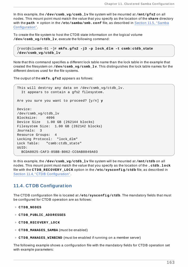
In this example, the /dev/csmb_vg/csmb_lv file system will be mounted at /mnt/gfs2 on allnodes. This mount point must match the value that you specify as the location of the share directorywith the path = option in the /etc/samba/smb.conf file, as described in Section 11.5, “SambaConfiguration” .
To create the file system to host the CTDB state information on the logical volume /dev/csmb_vg/ctdb_lv, execute the following command:
[root@clusmb-01 ~]# mkfs.gfs2 -j3 -p lock_dlm -t csmb:ctdb_state /dev/csmb_vg/ctdb_lv
Note that this command specifies a different lock table name than the lock table in the example thatcreated the filesystem on /dev/csmb_vg/csmb_lv. This distinguishes the lock table names for thedifferent devices used for the file systems.
The output of the mkfs.gfs2 appears as follows:
This will destroy any data on /dev/csmb_vg/ctdb_lv. It appears to contain a gfs2 filesystem.
Are you sure you want to proceed? [y/n] y
Device:/dev/csmb_vg/ctdb_lvBlocksize: 4096Device Size 1.00 GB (262144 blocks)Filesystem Size: 1.00 GB (262142 blocks)Journals: 3Resource Groups: 4Locking Protocol: "lock_dlm"Lock Table: "csmb:ctdb_state"UUID: BCDA8025-CAF3-85BB-B062-CC0AB8849A03
In this example, the /dev/csmb_vg/ctdb_lv file system will be mounted at /mnt/ctdb on allnodes. This mount point must match the value that you specify as the location of the .ctdb.lockfile with the CTDB_RECOVERY_LOCK option in the /etc/sysconfig/ctdb file, as described inSection 11.4, “CTDB Configuration” .
11.4 . CTDB Configurat ion
The CTDB configuration file is located at /etc/sysconfig/ctdb. The mandatory fields that mustbe configured for CTDB operation are as follows:
CTDB_NODES
CTDB_PUBLIC_ADDRESSES
CTDB_RECOVERY_LOCK
CTDB_MANAGES_SAMBA (must be enabled)
CTDB_MANAGES_WINBIND (must be enabled if running on a member server)
The following example shows a configuration file with the mandatory fields for CTDB operation setwith example parameters:
Chapt er 1 1 . Clust ered Samba Configurat ion
163

CTDB_NODES=/etc/ctdb/nodesCTDB_PUBLIC_ADDRESSES=/etc/ctdb/public_addressesCTDB_RECOVERY_LOCK="/mnt/ctdb/.ctdb.lock"CTDB_MANAGES_SAMBA=yesCTDB_MANAGES_WINBIND=yes
The meaning of these parameters is as follows.
CTDB_NODES
Specifies the location of the file which contains the cluster node list.
The /etc/ctdb/nodes file that CTDB_NODES references simply lists the IP addresses ofthe cluster nodes, as in the following example:
192.168.1.151192.168.1.152192.168.1.153
In this example, there is only one interface/IP on each node that is used for bothcluster/CTDB communication and serving clients. However, it is highly recommended thateach cluster node have two network interfaces so that one set of interfaces can bededicated to cluster/CTDB communication and another set of interfaces can be dedicatedto public client access. Use the appropriate IP addresses of the cluster network here andmake sure the hostnames/IP addresses used in the cluster.conf file are the same.Similarly, use the appropriate interfaces of the public network for client access in the public_addresses file.
It is critical that the /etc/ctdb/nodes file is identical on all nodes because the ordering isimportant and CTDB will fail if it finds different information on different nodes.
CTDB_PUBLIC_ADDRESSES
Specifies the location of the file that lists the IP addresses that can be used to access theSamba shares exported by this cluster. These are the IP addresses that you shouldconfigure in DNS for the name of the clustered Samba server and are the addresses thatCIFS clients will connect to. Configure the name of the clustered Samba server as one DNStype A record with multiple IP addresses and let round-robin DNS distribute the clientsacross the nodes of the cluster.
For this example, we have configured a round-robin DNS entry csmb-server with all theaddresses listed in the /etc/ctdb/public_addresses file. DNS will distribute theclients that use this entry across the cluster in a round-robin fashion.
The contents of the /etc/ctdb/public_addresses file on each node are as follows:
192.168.1.201/0 eth0192.168.1.202/0 eth0192.168.1.203/0 eth0
This example uses three addresses that are currently unused on the network. In your ownconfiguration, choose addresses that can be accessed by the intended clients.
Alternately, this example shows the contents of the /etc/ctdb/public_addresses filesin a cluster in which there are three nodes but a total of four public addresses. In thisexample, IP address 198.162.2.1 can be hosted by either node 0 or node 1 and will beavailable to clients as long as at least one of these nodes is available. Only if both nodes 0
Red Hat Ent erprise Linux 6 Clust er Administ rat ion
164

and 1 fail does this public address become unavailable to clients. All other publicaddresses can only be served by one single node respectively and will therefore only beavailable if the respective node is also available.
The /etc/ctdb/public_addresses file on node 0 includes the following contents:
198.162.1.1/24 eth0198.162.2.1/24 eth1
The /etc/ctdb/public_addresses file on node 1 includes the following contents:
198.162.2.1/24 eth1198.162.3.1/24 eth2
The /etc/ctdb/public_addresses file on node 2 includes the following contents:
198.162.3.2/24 eth2
CTDB_RECOVERY_LOCK
Specifies a lock file that CTDB uses internally for recovery. This file must reside on sharedstorage such that all the cluster nodes have access to it. The example in this section usesthe GFS2 file system that will be mounted at /mnt/ctdb on all nodes. This is different fromthe GFS2 file system that will host the Samba share that will be exported. This recovery lockfile is used to prevent split-brain scenarios. With newer versions of CTDB (1.0.112 andlater), specifying this file is optional as long as it is substituted with another split-brainprevention mechanism.
CTDB_MANAGES_SAMBA
When enabling by setting it to yes, specifies that CTDB is allowed to start and stop theSamba service as it deems necessary to provide service migration/failover.
When CTDB_MANAGES_SAMBA is enabled, you should disable automatic init startup ofthe smb and nmb daemons by executing the following commands:
[root@clusmb-01 ~]# chkconfig snb off[root@clusmb-01 ~]# chkconfig nmb off
CTDB_MANAGES_WINBIND
When enabling by setting it to yes, specifies that CTDB is allowed to start and stop the winbind daemon as required. This should be enabled when you are using CTDB in aWindows domain or in active directory security mode.
When CTDB_MANAGES_WINBIND is enabled, you should disable automatic init startupof the winbind daemon by executing the following command:
[root@clusmb-01 ~]# chkconfig windinbd off
11.5. Samba Configurat ion
The Samba configuration file smb.conf is located at /etc/samba/smb.conf in this example. Itcontains the following parameters:
Chapt er 1 1 . Clust ered Samba Configurat ion
165

[global] guest ok = yes clustering = yes netbios name = csmb-server[csmb] comment = Clustered Samba public = yes path = /mnt/gfs2/share writeable = yes ea support = yes
This example exports a share with name csmb located at /mnt/gfs2/share. This is different fromthe GFS2 shared filesystem at /mnt/ctdb/.ctdb.lock that we specified as the CTDB_RECOVERY_LOCK parameter in the CTDB configuration file at /etc/sysconfig/ctdb.
In this example, we will create the share directory in /mnt/gfs2 when we mount it for the first time.The clustering = yes entry instructs Samba to use CTDB. The netbios name = csmb-server entry explicitly sets all the nodes to have a common NetBIOS name. The ea supportparameter is required if you plan to use extended attributes.
The smb.conf configuration file must be identical on all of the cluster nodes.
Samba also offers registry-based configuration using the net conf command to automatically keepconfiguration in sync between cluster members without having to manually copy configuration filesamong the cluster nodes. For information on the net conf command, refer to the net(8) man page.
11.6. Start ing CTDB and Samba Services
After starting up the cluster, you must mount the GFS2 file systems that you created, as described inSection 11.3, “GFS2 Configuration” . The permissions on the Samba share directory and useraccounts on the cluster nodes should be set up for client access.
Execute the following command on all of the nodes to start up the ctdbd daemon. Since thisexample configured CTDB with CTDB_MANAGES_SAMBA=yes, CTDB will also start up the Sambaservice on all nodes and export all configured Samba shares.
[root@clusmb-01 ~]# service ctdb start
It can take a couple of minutes for CTDB to start Samba, export the shares, and stabilize. Executing ctdb status shows the status of CTDB, as in the following example:
[root@clusmb-01 ~]# ctdb statusNumber of nodes:3pnn:0 192.168.1.151 OK (THIS NODE)pnn:1 192.168.1.152 OKpnn:2 192.168.1.153 OKGeneration:1410259202Size:3hash:0 lmaster:0hash:1 lmaster:1hash:2 lmaster:2Recovery mode:NORMAL (0)Recovery master:0
Red Hat Ent erprise Linux 6 Clust er Administ rat ion
166

When you see that all nodes are "OK", it is safe to move on to use the clustered Samba server, asdescribed in Section 11.7, “Using the Clustered Samba Server” .
11.7. Using the Clustered Samba Server
Clients can connect to the Samba share that was exported by connecting to one of the IP addressesspecified in the /etc/ctdb/public_addresses file, or using the csmb-server DNS entry weconfigured earlier, as shown below:
[root@clusmb-01 ~]# mount -t cifs //csmb-server/csmb /mnt/sambashare -o user=testmonkey
or
[user@clusmb-01 ~]$ smbclient //csmb-server/csmb
Chapt er 1 1 . Clust ered Samba Configurat ion
167

Fence Device Parameters
This appendix provides tables with parameter descriptions of fence devices. You can configure theparameters with luci , by using the ccs command, or by editing the etc/cluster/cluster.conffile. For a comprehensive list and description of the fence device parameters for each fence agent,refer to the man page for that agent.
Note
The Name parameter for a fence device specifies an arbitrary name for the device that will beused by Red Hat High Availability Add-On. This is not the same as the DNS name for thedevice.
Note
Certain fence devices have an optional Password Script parameter. The Password Scriptparameter allows you to specify that a fence-device password is supplied from a script ratherthan from the Password parameter. Using the Password Script parameter supersedes thePassword parameter, allowing passwords to not be visible in the cluster configuration file(/etc/cluster/cluster.conf).
Table A.1, “Fence Device Summary” lists the fence devices, the fence device agents associated withthe fence devices, and provides a reference to the table documenting the parameters for the fencedevices.
Table A.1. Fence Device Summary
Fence Device Fence Agent Reference to ParameterDescript ion
APC PowerSwitch(telnet/SSH)
fence_apc Table A.2, “APC Power Switch(telnet/SSH)”
APC PowerSwitch overSNMP
fence_apc_snmp Table A.3, “APC Power Switchover SNMP”
BrocadeFabric Switch
fence_brocade Table A.4, “Brocade FabricSwitch”
Cisco MDS fence_cisco_mds Table A.5, “Cisco MDS”Cisco UCS fence_cisco_ucs Table A.6, “Cisco UCS”Dell DRAC 5 fence_drac5 Table A.7, “Dell DRAC 5”Dell iDRAC fence_idrac Table A.22, “ IPMI (Intelligent
Platform ManagementInterface) LAN, Dell iDrac, IBMIntegrated ManagementModule, HPiLO3, HPiLO4”
Eaton NetworkPower Switch(SNMPInterface)
fence_eaton_snmp Table A.8, “Eaton NetworkPower Controller (SNMPInterface) (Red Hat EnterpriseLinux 6.4 and later)”
Red Hat Ent erprise Linux 6 Clust er Administ rat ion
168

EgeneraBladeFrame
fence_egenera Table A.9, “EgeneraBladeFrame”
ePowerSwitch fence_eps Table A.10, “ePowerSwitch”Fence kdump fence_kdump Table A.11, “Fence kdump”Fence virt fence_virt Table A.12, “Fence virt”FujitsuSiemensRemoteviewService Board(RSB)
fence_rsb Table A.13, “Fujitsu SiemensRemoteview Service Board(RSB)”
HPBladeSystem
fence_hpblade Table A.14, “HP BladeSystem(Red Hat Enterprise Linux 6.4and later)”
HP iLO Device(IntegratedLights Out),
fence_ilo Table A.15, “HP iLO (IntegratedLights Out) and HP iLO2”
HP iLO2 fence_ilo2 Table A.15, “HP iLO (IntegratedLights Out) and HP iLO2”
HPiLO3 fence_ilo3 Table A.22, “ IPMI (IntelligentPlatform ManagementInterface) LAN, Dell iDrac, IBMIntegrated ManagementModule, HPiLO3, HPiLO4”
HPiLO4 fence_ilo4 Table A.22, “ IPMI (IntelligentPlatform ManagementInterface) LAN, Dell iDrac, IBMIntegrated ManagementModule, HPiLO3, HPiLO4”
HP iLO(IntegratedLights Out) MP
fence_ilo_mp Table A.16, “HP iLO (IntegratedLights Out) MP”
IBMBladeCenter
fence_bladecenter Table A.17, “ IBM BladeCenter”
IBMBladeCenterSNMP
fence_ibmblade Table A.18, “ IBM BladeCenterSNMP”
IBM IntegratedManagementModule
fence_imm Table A.22, “ IPMI (IntelligentPlatform ManagementInterface) LAN, Dell iDrac, IBMIntegrated ManagementModule, HPiLO3, HPiLO4”
IBM iPDU fence_ipdu Table A.19, “ IBM iPDU (RedHat Enterprise Linux 6.4 andlater)”
IF MIB fence_ifmib Table A.20, “ IF MIB”Intel Modular fence_intelmodular Table A.21, “ Intel Modular”IPMI(IntelligentPlatformManagementInterface) Lan
fence_ipmilan Table A.22, “ IPMI (IntelligentPlatform ManagementInterface) LAN, Dell iDrac, IBMIntegrated ManagementModule, HPiLO3, HPiLO4”
Fence Device Fence Agent Reference to ParameterDescript ion
Fence Device Paramet ers
169

RHEV-M RESTAPI
fence_rhevm Table A.23, “RHEV-M RESTAPI (RHEL 6.2 and lateragainst RHEV 3.0 and later)”
SCSI Fencing fence_scsi Table A.24, “SCSI ReservationFencing”
VMwareFencing(SOAPInterface)
fence_vmware_soap Table A.25, “VMware Fencing(SOAP Interface) (Red HatEnterprise Linux 6.2 and later)”
WTI PowerSwitch
fence_wti Table A.26, “WTI PowerSwitch”
Fence Device Fence Agent Reference to ParameterDescript ion
Table A.2, “APC Power Switch (telnet/SSH)” lists the fence device parameters used by fence_apc,the fence agent for APC over telnet/SSH.
Table A.2. APC Power Switch ( telnet /SSH)
luci Field cluster.conf At t ribute
Descript ion
Name name A name for the APC device connected to the cluster into whichthe fence daemon logs via telnet/ssh.
IP Address orHostname
ipaddr The IP address or hostname assigned to the device.
IP Port(optional)
ipport The TCP port to use to connect to the device. The default port is23, or 22 if Use SSH is selected.
Login login The login name used to access the device.Password passwd The password used to authenticate the connection to the device.PasswordScript(optional)
passwd_script
The script that supplies a password for access to the fencedevice. Using this supersedes the Password parameter.
Power Wait(seconds)
power_wait Number of seconds to wait after issuing a power off or power oncommand.
Power Timeout(seconds)
power_timeout
Number of seconds to wait before testing for a status changeafter issuing a power on or power on command. The defaultvalue is 20.
Shell Timeout(seconds)
shell_timeout
Number of seconds to wait for a command prompt after issuing acommand. The default value is 3.
Login Timeout(seconds)
login_timeout
Number of seconds to wait for a command prompt after login.The default value is 5.
Times to RetryPower OnOperation
retry_on Number of attempts to retry a power on operation. The defaultvalue is 1.
Port port The port.Switch(optional)
switch The switch number for the APC switch that connects to the nodewhen you have multiple daisy-chained switches.
Delay(optional)
delay The number of seconds to wait before fencing is started. Thedefault value is 0.
Use SSH secure Indicates that system will use SSH to access the device. Whenusing SSH, you must specify either a password, a passwordscript, or an identity file.
SSH Options ssh_options SSH options to use. The default value is -1 -c blowfish.
Red Hat Ent erprise Linux 6 Clust er Administ rat ion
170

Path to SSHIdentity File
identity_file
The identity file for SSH.
luci Field cluster.conf At t ribute
Descript ion
Table A.3, “APC Power Switch over SNMP” lists the fence device parameters used by fence_apc_snmp, the fence agent for APC that logs into the SNP device via the SNMP protocol.
Table A.3. APC Power Switch over SNMP
luci Field cluster.conf At t ribute
Descript ion
Name name A name for the APC device connected to the cluster into whichthe fence daemon logs via the SNMP protocol.
IP Address orHostname
ipaddr The IP address or hostname assigned to the device.
UDP/TCP port udpport The UDP/TCP port to use for connection with the device; thedefault value is 161.
Login login The login name used to access the device.Password passwd The password used to authenticate the connection to the device.PasswordScript(optional)
passwd_script
The script that supplies a password for access to the fencedevice. Using this supersedes the Password parameter.
SNMP Version snmp_version
The SNMP version to use (1, 2c, 3); the default value is 1.
SNMPCommunity
community The SNMP community string; the default value is private.
SNMP SecurityLevel
snmp_sec_level
The SNMP security level (noAuthNoPriv, authNoPriv, authPriv).
SNMPAuthenticationProtocol
snmp_auth_prot
The SNMP authentication protocol (MD5, SHA).
SNMP PrivacyProtocol
snmp_priv_prot
The SNMP privacy protocol (DES, AES).
SNMP PrivacyProtocolPassword
snmp_priv_passwd
The SNMP privacy protocol password.
SNMP PrivacyProtocol Script
snmp_priv_passwd_script
The script that supplies a password for SNMP privacy protocol.Using this supersedes the SNMP privacy protocol passwordparameter.
Power Wait(seconds)
power_wait Number of seconds to wait after issuing a power off or power oncommand.
Power Timeout(seconds)
power_timeout
Number of seconds to wait before testing for a status changeafter issuing a power on or power on command. The defaultvalue is 20.
Shell Timeout(seconds)
shell_timeout
Number of seconds to wait for a command prompt after issuing acommand. The default value is 3.
Login Timeout(seconds)
login_timeout
Number of seconds to wait for a command prompt after login.The default value is 5.
Times to RetryPower OnOperation
retry_on Number of attempts to retry a power on operation. The defaultvalue is 1.
Fence Device Paramet ers
171

Port (Outlet)Number
port The port.
Delay(optional)
delay The number of seconds to wait before fencing is started. Thedefault value is 0.
luci Field cluster.conf At t ribute
Descript ion
Table A.4, “Brocade Fabric Switch” lists the fence device parameters used by fence_brocade, thefence agent for Brocade FC switches.
Table A.4 . Brocade Fabric Switch
luci Field cluster.conf At t ribute
Descript ion
Name name A name for the Brocade device connected to the cluster.IP Address orHostname
ipaddr The IP address assigned to the device.
Login login The login name used to access the device.Password passwd The password used to authenticate the connection to the device.PasswordScript(optional)
passwd_script
The script that supplies a password for access to the fencedevice. Using this supersedes the Password parameter.
Force IPFamily
inet4_only, inet6_only
Force the agent to use IPv4 or IPv6 addresses only
ForceCommandPrompt
cmd_prompt The command prompt to use. The default value is ’\$’.
Power Wait(seconds)
power_wait Number of seconds to wait after issuing a power off or power oncommand.
Power Timeout(seconds)
power_timeout
Number of seconds to wait before testing for a status changeafter issuing a power on or power on command. The defaultvalue is 20.
Shell Timeout(seconds)
shell_timeout
Number of seconds to wait for a command prompt after issuing acommand. The default value is 3.
Login Timeout(seconds)
login_timeout
Number of seconds to wait for a command prompt after login.The default value is 5.
Times to RetryPower OnOperation
retry_on Number of attempts to retry a power on operation. The defaultvalue is 1.
Port port The switch outlet number.Delay(optional)
delay The number of seconds to wait before fencing is started. Thedefault value is 0.
Use SSH secure Indicates that the system will use SSH to access the device.When using SSH, you must specify either a password, apassword script, or an identity file.
SSH Options ssh_options SSH options to use. The default value is -1 -c blowfish.Path to SSHIdentity File
identity_file
The identity file for SSH.
Red Hat Ent erprise Linux 6 Clust er Administ rat ion
172

Unfencing unfencesection of theclusterconfigurationfile
When enabled, this ensures that a fenced node is not re-enableduntil the node has been rebooted. This is necessary for non-power fence methods (that is, SAN/storage fencing). When youconfigure a device that requires unfencing, the cluster must firstbe stopped and the full configuration including devices andunfencing must be added before the cluster is started. For moreinformation about unfencing a node, refer to the fence_node(8)man page. For information about configuring unfencing in thecluster configuration file, refer to Section 7.3, “ConfiguringFencing” . For information about configuring unfencing with the ccs command, refer to Section 5.7.2, “Configuring a SingleStorage-Based Fence Device for a Node” .
luci Field cluster.conf At t ribute
Descript ion
Table A.5, “Cisco MDS” lists the fence device parameters used by fence_cisco_mds, the fenceagent for Cisco MDS.
Table A.5. Cisco MDS
luci Field cluster.conf At t ribute
Descript ion
Name name A name for the Cisco MDS 9000 series device with SNMPenabled.
IP Address orHostname
ipaddr The IP address or hostname assigned to the device.
UDP/TCP port(optional)
udpport The UDP/TCP port to use for connection with the device; thedefault value is 161.
Login login The login name used to access the device.Password passwd The password used to authenticate the connection to the device.PasswordScript(optional)
passwd_script
The script that supplies a password for access to the fencedevice. Using this supersedes the Password parameter.
SNMP Version snmp_version
The SNMP version to use (1, 2c, 3).
SNMPCommunity
community The SNMP community string.
SNMP SecurityLevel
snmp_sec_level
The SNMP security level (noAuthNoPriv, authNoPriv, authPriv).
SNMPAuthenticationProtocol
snmp_auth_prot
The SNMP authentication protocol (MD5, SHA).
SNMP PrivacyProtocol
snmp_priv_prot
The SNMP privacy protocol (DES, AES).
SNMP PrivacyProtocolPassword
snmp_priv_passwd
The SNMP privacy protocol password.
SNMP PrivacyProtocol Script
snmp_priv_passwd_script
The script that supplies a password for SNMP privacy protocol.Using this supersedes the SNMP privacy protocol passwordparameter.
Power Wait(seconds)
power_wait Number of seconds to wait after issuing a power off or power oncommand.
Fence Device Paramet ers
173

Power Timeout(seconds)
power_timeout
Number of seconds to wait before testing for a status changeafter issuing a power on or power on command. The defaultvalue is 20.
Shell Timeout(seconds)
shell_timeout
Number of seconds to wait for a command prompt after issuing acommand. The default value is 3.
Login Timeout(seconds)
login_timeout
Number of seconds to wait for a command prompt after login.The default value is 5.
Times to RetryPower OnOperation
retry_on Number of attempts to retry a power on operation. The defaultvalue is 1.
Port (Outlet)Number
port The port.
Delay(optional)
delay The number of seconds to wait before fencing is started. Thedefault value is 0.
luci Field cluster.conf At t ribute
Descript ion
Table A.6, “Cisco UCS” lists the fence device parameters used by fence_cisco_ucs, the fenceagent for Cisco UCS.
Table A.6 . Cisco UCS
luci Field cluster.conf At t ribute
Descript ion
Name name A name for the Cisco UCS device.IP Address orHostname
ipaddr The IP address or hostname assigned to the device.
IP port(optional)
ipport The TCP port to use to connect to the device.
Login login The login name used to access the device.Password passwd The password used to authenticate the connection to the device.PasswordScript(optional)
passwd_script
The script that supplies a password for access to the fencedevice. Using this supersedes the Password parameter.
Use SSL ssl Use SSL connections to communicate with the device.Sub-Organization
suborg Additional path needed to access suborganization.
Power Wait(seconds)
power_wait Number of seconds to wait after issuing a power off or power oncommand.
Power Timeout(seconds)
power_timeout
Number of seconds to wait before testing for a status changeafter issuing a power on or power on command. The defaultvalue is 20.
Shell Timeout(seconds)
shell_timeout
Number of seconds to wait for a command prompt after issuing acommand. The default value is 3.
Login Timeout(seconds)
login_timeout
Number of seconds to wait for a command prompt after login.The default value is 5.
Times to RetryPower OnOperation
retry_on Number of attempts to retry a power on operation. The defaultvalue is 1.
Port (Outlet)Number
port Name of virtual machine.
Red Hat Ent erprise Linux 6 Clust er Administ rat ion
174

Delay(optional)
delay The number of seconds to wait before fencing is started. Thedefault value is 0.
luci Field cluster.conf At t ribute
Descript ion
Table A.7, “Dell DRAC 5” lists the fence device parameters used by fence_drac5, the fence agentfor Dell DRAC 5.
Table A.7. Dell DRAC 5
luci Field cluster.conf At t ribute
Descript ion
Name name The name assigned to the DRAC.IP Address orHostname
ipaddr The IP address or hostname assigned to the DRAC.
IP Port(optional)
ipport The TCP port to use to connect to the device.
Login login The login name used to access the DRAC.Password passwd The password used to authenticate the connection to the DRAC.PasswordScript(optional)
passwd_script
The script that supplies a password for access to the fencedevice. Using this supersedes the Password parameter.
Use SSH secure Indicates that the system will use SSH to access the device.When using SSH, you must specify either a password, apassword script, or an identity file.
SSH Options ssh_options SSH options to use. The default value is -1 -c blowfish.Path to SSHIdentity File
identity_file
The identity file for SSH.
Module Name module_name
(optional) The module name for the DRAC when you havemultiple DRAC modules.
ForceCommandPrompt
cmd_prompt The command prompt to use. The default value is ’\$’.
Power Wait(seconds)
power_wait Number of seconds to wait after issuing a power off or power oncommand.
Delay(seconds)
delay The number of seconds to wait before fencing is started. Thedefault value is 0.
Power Timeout(seconds)
power_timeout
Number of seconds to wait before testing for a status changeafter issuing a power on or power on command. The defaultvalue is 20.
Shell Timeout(seconds)
shell_timeout
Number of seconds to wait for a command prompt after issuing acommand. The default value is 3.
Login Timeout(seconds)
login_timeout
Number of seconds to wait for a command prompt after login.The default value is 5.
Times to RetryPower OnOperation
retry_on Number of attempts to retry a power on operation. The defaultvalue is 1.
Table A.8, “Eaton Network Power Controller (SNMP Interface) (Red Hat Enterprise Linux 6.4 andlater)” lists the fence device parameters used by fence_eaton_snmp, the fence agent for the Eatonover SNMP network power switch.
Fence Device Paramet ers
175

Table A.8. Eaton Network Power Contro ller (SNMP Interface) (Red Hat Enterprise Linux6 .4 and later)
luci Field cluster.conf At t ribute
Descript ion
Name name A name for the Eaton network power switch connected to thecluster.
IP Address orHostname
ipaddr The IP address or hostname assigned to the device.
UDP/TCP Port(optional)
udpport The UDP/TCP port to use for connection with the device; thedefault value is 161.
Login login The login name used to access the device.Password passwd The password used to authenticate the connection to the device.PasswordScript(optional)
passwd_script
The script that supplies a password for access to the fencedevice. Using this supersedes the Password parameter.
SNMP Version snmp_version
The SNMP version to use (1, 2c, 3); the default value is 1.
SNMPCommunity
community The SNMP community string; the default value is private.
SNMP SecurityLevel
snmp_sec_level
The SNMP security level (noAuthNoPriv, authNoPriv, authPriv).
SNMPAuthenticationProtocol
snmp_auth_prot
The SNMP authentication protocol (MD5, SHA).
SNMP PrivacyProtocol
snmp_priv_prot
The SNMP privacy protocol (DES, AES).
SNMP PrivacyProtocolPassword
snmp_priv_passwd
The SNMP privacy protocol password.
SNMP PrivacyProtocol Script
snmp_priv_passwd_script
The script that supplies a password for SNMP privacy protocol.Using this supersedes the SNMP privacy protocol passwordparameter.
Power wait(seconds)
power_wait Number of seconds to wait after issuing a power off or power oncommand.
Power Timeout(seconds)
power_timeout
Number of seconds to wait before testing for a status changeafter issuing a power on or power on command. The defaultvalue is 20.
Shell Timeout(seconds)
shell_timeout
Number of seconds to wait for a command prompt after issuing acommand. The default value is 3.
Login Timeout(seconds)
login_timeout
Number of seconds to wait for a command prompt after login.The default value is 5.
Times to RetryPower OnOperation
retry_on Number of attempts to retry a power on operation. The defaultvalue is 1.
Port (Outlet)Number
port Physical plug number or name of virtual machine. Thisparameter is always required.
Delay(optional)
delay The number of seconds to wait before fencing is started. Thedefault value is 0.
Table A.9, “Egenera BladeFrame” lists the fence device parameters used by fence_egenera, thefence agent for the Egenera BladeFrame.
Red Hat Ent erprise Linux 6 Clust er Administ rat ion
176

Table A.9 . Egenera BladeFrame
luci Field cluster.conf At t ribute
Descript ion
Name name A name for the Egenera BladeFrame device connected to thecluster.
CServer cserver The hostname (and optionally the username in the form of username@hostname) assigned to the device. Refer to thefence_egenera(8) man page for more information.
ESH Path(optional)
esh The path to the esh command on the cserver (default is/opt/panmgr/bin/esh)
Username user The login name. The default value is root.lpan lpan The logical process area network (LPAN) of the device.pserver pserver The processing blade (pserver) name of the device.Delay(optional)
delay The number of seconds to wait before fencing is started. Thedefault value is 0.
Unfencing unfencesection of theclusterconfigurationfile
When enabled, this ensures that a fenced node is not re-enableduntil the node has been rebooted. This is necessary for non-power fence methods (that is, SAN/storage fencing). When youconfigure a device that requires unfencing, the cluster must firstbe stopped and the full configuration including devices andunfencing must be added before the cluster is started. For moreinformation about unfencing a node, refer to the fence_node(8)man page. For information about configuring unfencing in thecluster configuration file, refer to Section 7.3, “ConfiguringFencing” . For information about configuring unfencing with the ccs command, refer to Section 5.7.2, “Configuring a SingleStorage-Based Fence Device for a Node” .
Table A.10, “ePowerSwitch” lists the fence device parameters used by fence_eps, the fence agentfor ePowerSwitch.
Table A.10. ePowerSwitch
luci Field cluster.conf At t ribute
Descript ion
Name name A name for the ePowerSwitch device connected to the cluster.IP Address orHostname
ipaddr The IP address or hostname assigned to the device.
Login login The login name used to access the device.Password passwd The password used to authenticate the connection to the device.PasswordScript(optional)
passwd_script
The script that supplies a password for access to the fencedevice. Using this supersedes the Password parameter.
Name ofHidden Page
hidden_page
The name of the hidden page for the device.
Times to RetryPower OnOperation
retry_on Number of attempts to retry a power on operation. The defaultvalue is 1.
Port (Outlet)Number
port Physical plug number or name of virtual machine.
Delay(optional)
delay The number of seconds to wait before fencing is started. Thedefault value is 0.
Fence Device Paramet ers
177

Table A.11, “Fence kdump” lists the fence device parameters used by fence_kdump, the fence agentfor kdump crash recovery service. Note that fence_kdump is not a replacement for traditionalfencing methods; The fence_kdump agent can detect only that a node has entered the kdump crashrecovery service. This allows the kdump crash recovery service to complete without being preemptedby traditional power fencing methods.
Table A.11. Fence kdump
luci Field cluster.conf At t ribute
Descript ion
Name name A name for the fence_kdump device.IP Family family IP network family. The default value is auto .IP Port(optional)
ipport IP port number that the fence_kdump agent will use to listen formessages. The default value is 7410.
OperationTimeout(seconds)(optional)
timeout Number of seconds to wait for message from failed node.
Node name nodename Name or IP address of the node to be fenced.
Table A.12, “Fence virt” lists the fence device parameters used by fence_virt, the fence agent for aFence virt fence device.
Table A.12. Fence virt
luci Field cluster.conf At t ribute
Descript ion
Name name A name for the Fence virt fence device.Serial Device serial_dev
iceOn the host, the serial device must be mapped in each domain'sconfiguration file. For more information, see the fence_virt.conf man page. If this field is specified, it causesthe fence_virt fencing agent to operate in serial mode. Notspecifying a value causes the fence_virt fencing agent tooperate in VM channel mode.
SerialParameters
serial_params
The serial parameters. The default is 115200, 8N1.
VM Channel IPAddress
channel_address
The channel IP. The default value is 10.0.2.179.
Port orDomain(deprecated)
port Virtual machine (domain UUID or name) to fence.
ipport The channel port. The default value is 1229, which is the valueused when configuring this fence device with luci .
Timeout timeout Fencing timeout, in seconds. The default value is 30.
Table A.13, “Fujitsu Siemens Remoteview Service Board (RSB)” lists the fence device parametersused by fence_rsb, the fence agent for Fujitsu-Siemens RSB.
Table A.13. Fujitsu Siemens Remoteview Service Board (RSB)
luci Field cluster.conf At t ribute
Descript ion
Name name A name for the RSB to use as a fence device.
Red Hat Ent erprise Linux 6 Clust er Administ rat ion
178
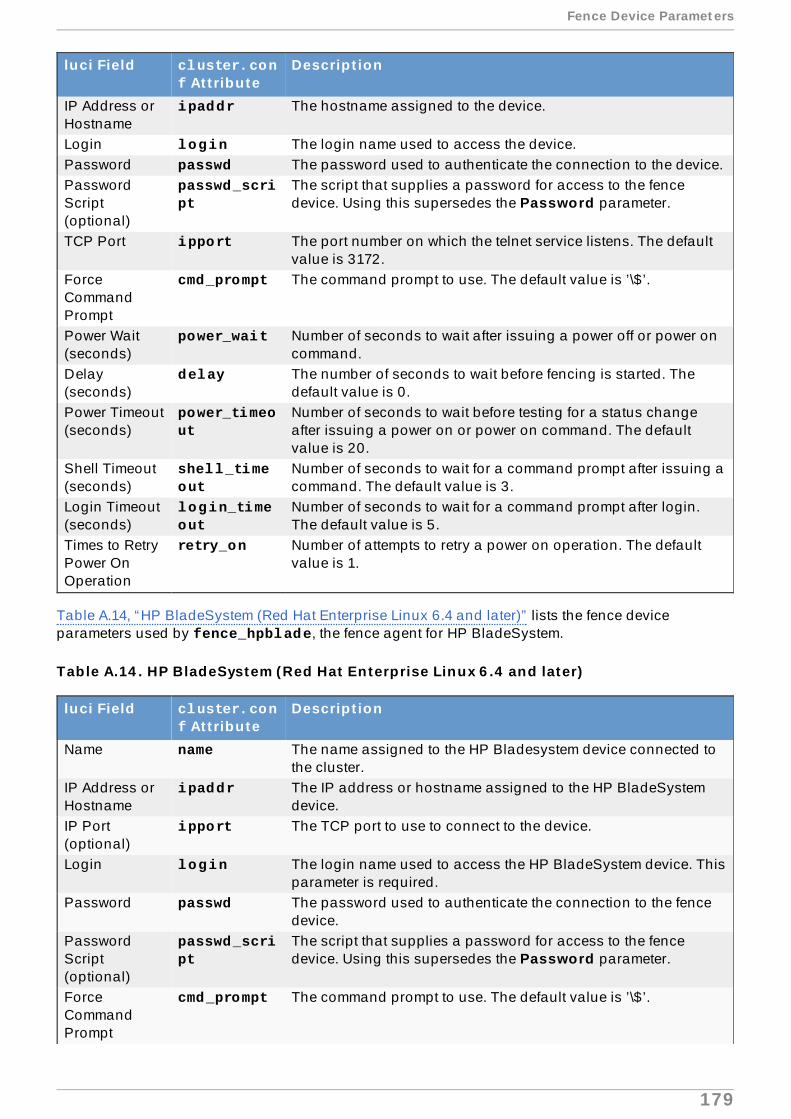
IP Address orHostname
ipaddr The hostname assigned to the device.
Login login The login name used to access the device.Password passwd The password used to authenticate the connection to the device.PasswordScript(optional)
passwd_script
The script that supplies a password for access to the fencedevice. Using this supersedes the Password parameter.
TCP Port ipport The port number on which the telnet service listens. The defaultvalue is 3172.
ForceCommandPrompt
cmd_prompt The command prompt to use. The default value is ’\$’.
Power Wait(seconds)
power_wait Number of seconds to wait after issuing a power off or power oncommand.
Delay(seconds)
delay The number of seconds to wait before fencing is started. Thedefault value is 0.
Power Timeout(seconds)
power_timeout
Number of seconds to wait before testing for a status changeafter issuing a power on or power on command. The defaultvalue is 20.
Shell Timeout(seconds)
shell_timeout
Number of seconds to wait for a command prompt after issuing acommand. The default value is 3.
Login Timeout(seconds)
login_timeout
Number of seconds to wait for a command prompt after login.The default value is 5.
Times to RetryPower OnOperation
retry_on Number of attempts to retry a power on operation. The defaultvalue is 1.
luci Field cluster.conf At t ribute
Descript ion
Table A.14, “HP BladeSystem (Red Hat Enterprise Linux 6.4 and later)” lists the fence deviceparameters used by fence_hpblade, the fence agent for HP BladeSystem.
Table A.14 . HP BladeSystem (Red Hat Enterprise Linux 6 .4 and later)
luci Field cluster.conf At t ribute
Descript ion
Name name The name assigned to the HP Bladesystem device connected tothe cluster.
IP Address orHostname
ipaddr The IP address or hostname assigned to the HP BladeSystemdevice.
IP Port(optional)
ipport The TCP port to use to connect to the device.
Login login The login name used to access the HP BladeSystem device. Thisparameter is required.
Password passwd The password used to authenticate the connection to the fencedevice.
PasswordScript(optional)
passwd_script
The script that supplies a password for access to the fencedevice. Using this supersedes the Password parameter.
ForceCommandPrompt
cmd_prompt The command prompt to use. The default value is ’\$’.
Fence Device Paramet ers
179

Missing portreturns OFFinstead offailure
missing_as_off
Missing port returns OFF instead of failure.
Power Wait(seconds)
power_wait Number of seconds to wait after issuing a power off or power oncommand.
Power Timeout(seconds)
power_timeout
Number of seconds to wait before testing for a status changeafter issuing a power on or power on command. The defaultvalue is 20.
Shell Timeout(seconds)
shell_timeout
Number of seconds to wait for a command prompt after issuing acommand. The default value is 3.
Login Timeout(seconds)
login_timeout
Number of seconds to wait for a command prompt after login.The default value is 5.
Times to RetryPower OnOperation
retry_on Number of attempts to retry a power on operation. The defaultvalue is 1.
Use SSH secure Indicates that the system will use SSH to access the device.When using SSH, you must specify either a password, apassword script, or an identity file.
SSH Options ssh_options SSH options to use. The default value is -1 -c blowfish.Path to SSHIdentity File
identity_file
The identity file for SSH.
luci Field cluster.conf At t ribute
Descript ion
The fence agents for HP iLO devices fence_ilo and HP iLO2 devices fence_ilo2. share thesame implementation. Table A.15, “HP iLO (Integrated Lights Out) and HP iLO2” lists the fence deviceparameters used by these agents.
Table A.15. HP iLO ( In tegrated Lights Out ) and HP iLO2
luci Field cluster.conf At t ribute
Descript ion
Name name A name for the server with HP iLO support.IP Address orHostname
ipaddr The IP address or hostname assigned to the device.
IP Port(optional)
ipport TCP port to use for connection with the device. The default valueis 443.
Login login The login name used to access the device.Password passwd The password used to authenticate the connection to the device.PasswordScript(optional)
passwd_script
The script that supplies a password for access to the fencedevice. Using this supersedes the Password parameter.
Power Wait(seconds)
power_wait Number of seconds to wait after issuing a power off or power oncommand.
Delay(seconds)
delay The number of seconds to wait before fencing is started. Thedefault value is 0.
Power Timeout(seconds)
power_timeout
Number of seconds to wait before testing for a status changeafter issuing a power on or power on command. The defaultvalue is 20.
Shell Timeout(seconds)
shell_timeout
Number of seconds to wait for a command prompt after issuing acommand. The default value is 3.
Red Hat Ent erprise Linux 6 Clust er Administ rat ion
180

Login Timeout(seconds)
login_timeout
Number of seconds to wait for a command prompt after login.The default value is 5.
Times to RetryPower OnOperation
retry_on Number of attempts to retry a power on operation. The defaultvalue is 1.
luci Field cluster.conf At t ribute
Descript ion
Table A.16, “HP iLO (Integrated Lights Out) MP” lists the fence device parameters used by fence_ilo_mp, the fence agent for HP iLO MP devices.
Table A.16 . HP iLO ( In tegrated Lights Out ) MP
luci Field cluster.conf At t ribute
Descript ion
Name name A name for the server with HP iLO support.IP Address orHostname
ipaddr The IP address or hostname assigned to the device.
IP Port(optional)
ipport TCP port to use for connection with the device.
Login login The login name used to access the device.Password passwd The password used to authenticate the connection to the device.PasswordScript(optional)
passwd_script
The script that supplies a password for access to the fencedevice. Using this supersedes the Password parameter.
Use SSH secure Indicates that the system will use SSH to access the device.When using SSH, you must specify either a password, apassword script, or an identity file.
SSH Options ssh_options SSH options to use. The default value is -1 -c blowfish.Path to SSHIdentity File
identity_file
The Identity file for SSH.
ForceCommandPrompt
cmd_prompt The command prompt to use. The default value is ’MP>’, ’hpiLO->’.
Power Wait(seconds)
power_wait Number of seconds to wait after issuing a power off or power oncommand.
Delay(seconds)
delay The number of seconds to wait before fencing is started. Thedefault value is 0.
Power Timeout(seconds)
power_timeout
Number of seconds to wait before testing for a status changeafter issuing a power on or power on command. The defaultvalue is 20.
Shell Timeout(seconds)
shell_timeout
Number of seconds to wait for a command prompt after issuing acommand. The default value is 3.
Login Timeout(seconds)
login_timeout
Number of seconds to wait for a command prompt after login.The default value is 5.
Times to RetryPower OnOperation
retry_on Number of attempts to retry a power on operation. The defaultvalue is 1.
Table A.17, “ IBM BladeCenter” lists the fence device parameters used by fence_bladecenter, thefence agent for IBM BladeCenter.
Table A.17. IBM BladeCenter
Fence Device Paramet ers
181

luci Field cluster.conf At t ribute
Descript ion
Name name A name for the IBM BladeCenter device connected to the cluster.IP Address orHostname
ipaddr The IP address or hostname assigned to the device.
IP port(optional)
ipport TCP port to use for connection with the device.
Login login The login name used to access the device.Password passwd The password used to authenticate the connection to the device.PasswordScript(optional)
passwd_script
The script that supplies a password for access to the fencedevice. Using this supersedes the Password parameter.
Power Wait(seconds)
power_wait Number of seconds to wait after issuing a power off or power oncommand.
Power Timeout(seconds)
power_timeout
Number of seconds to wait before testing for a status changeafter issuing a power on or power on command. The defaultvalue is 20.
Shell Timeout(seconds)
shell_timeout
Number of seconds to wait for a command prompt after issuing acommand. The default value is 3.
Login Timeout(seconds)
login_timeout
Number of seconds to wait for a command prompt after login.The default value is 5.
Times to RetryPower OnOperation
retry_on Number of attempts to retry a power on operation. The defaultvalue is 1.
Use SSH secure Indicates that system will use SSH to access the device. Whenusing SSH, you must specify either a password, a passwordscript, or an identity file.
SSH Options ssh_options SSH options to use. The default value is -1 -c blowfish.Path to SSHIdentity File
identity_file
The identity file for SSH.
Table A.18, “ IBM BladeCenter SNMP” lists the fence device parameters used by fence_ibmblade,the fence agent for IBM BladeCenter over SNMP.
Table A.18. IBM BladeCenter SNMP
luci Field cluster.conf At t ribute
Descript ion
Name name A name for the IBM BladeCenter SNMP device connected to thecluster.
IP Address orHostname
ipaddr The IP address or hostname assigned to the device.
UDP/TCP Port(optional)
udpport UDP/TCP port to use for connections with the device; the defaultvalue is 161.
Login login The login name used to access the device.Password passwd The password used to authenticate the connection to the device.PasswordScript(optional)
passwd_script
The script that supplies a password for access to the fencedevice. Using this supersedes the Password parameter.
SNMP Version snmp_version
The SNMP version to use (1, 2c, 3); the default value is 1.
Red Hat Ent erprise Linux 6 Clust er Administ rat ion
182

SNMPCommunity
community The SNMP community string.
SNMP SecurityLevel
snmp_sec_level
The SNMP security level (noAuthNoPriv, authNoPriv, authPriv).
SNMPAuthenticationProtocol
snmp_auth_prot
The SNMP authentication protocol (MD5, SHA).
SNMP PrivacyProtocol
snmp_priv_prot
The SNMP privacy protocol (DES, AES).
SNMP privacyprotocolpassword
snmp_priv_passwd
The SNMP Privacy Protocol Password.
SNMP PrivacyProtocol Script
snmp_priv_passwd_script
The script that supplies a password for SNMP privacy protocol.Using this supersedes the SNMP privacy protocol passwordparameter.
Power Wait(seconds)
power_wait Number of seconds to wait after issuing a power off or power oncommand.
Power Timeout(seconds)
power_timeout
Number of seconds to wait before testing for a status changeafter issuing a power on or power on command. The defaultvalue is 20.
Shell Timeout(seconds)
shell_timeout
Number of seconds to wait for a command prompt after issuing acommand. The default value is 3.
Login Timeout(seconds)
login_timeout
Number of seconds to wait for a command prompt after login.The default value is 5.
Times to RetryPower OnOperation
retry_on Number of attempts to retry a power on operation. The defaultvalue is 1.
Port (Outlet)Number
port Physical plug number or name of virtual machine.
Delay(optional)
delay The number of seconds to wait before fencing is started. Thedefault value is 0.
luci Field cluster.conf At t ribute
Descript ion
Table A.19, “ IBM iPDU (Red Hat Enterprise Linux 6.4 and later)” lists the fence device parametersused by fence_ipdu, the fence agent for iPDU over SNMP devices.
Table A.19 . IBM iPDU (Red Hat Enterprise Linux 6 .4 and later)
luci Field cluster.conf At t ribute
Descript ion
Name name A name for the IBM iPDU device connected to the cluster intowhich the fence daemon logs via the SNMP protocol.
IP Address orHostname
ipaddr The IP address or hostname assigned to the device.
UDP/TCP Port udpport The UDP/TCP port to use for connection with the device; thedefault value is 161.
Login login The login name used to access the device.Password passwd The password used to authenticate the connection to the device.PasswordScript(optional)
passwd_script
The script that supplies a password for access to the fencedevice. Using this supersedes the Password parameter.
Fence Device Paramet ers
183

SNMP Version snmp_version
The SNMP version to use (1, 2c, 3); the default value is 1.
SNMPCommunity
community The SNMP community string; the default value is private.
SNMP SecurityLevel
snmp_sec_level
The SNMP security level (noAuthNoPriv, authNoPriv, authPriv).
SNMPAuthenticationProtocol
snmp_auth_prot
The SNMP Authentication Protocol (MD5, SHA).
SNMP PrivacyProtocol
snmp_priv_prot
The SNMP privacy protocol (DES, AES).
SNMP PrivacyProtocolPassword
snmp_priv_passwd
The SNMP privacy protocol password.
SNMP PrivacyProtocol Script
snmp_priv_passwd_script
The script that supplies a password for SNMP privacy protocol.Using this supersedes the SNMP privacy protocol passwordparameter.
Power Wait(seconds)
power_wait Number of seconds to wait after issuing a power off or power oncommand.
Power Timeout(seconds)
power_timeout
Number of seconds to wait before testing for a status changeafter issuing a power on or power on command. The defaultvalue is 20.
Shell Timeout(seconds)
shell_timeout
Number of seconds to wait for a command prompt after issuing acommand. The default value is 3.
Login Timeout(seconds)
login_timeout
Number of seconds to wait for a command prompt after login.The default value is 5.
Times to RetryPower OnOperation
retry_on Number of attempts to retry a power on operation. The defaultvalue is 1.
Port (Outlet)Number
port Physical plug number or name of virtual machine.
Delay(optional)
delay The number of seconds to wait before fencing is started. Thedefault value is 0.
luci Field cluster.conf At t ribute
Descript ion
Table A.20, “ IF MIB” lists the fence device parameters used by fence_ifmib, the fence agent for IF-MIB devices.
Table A.20. IF MIB
luci Field cluster.conf At t ribute
Descript ion
Name name A name for the IF MIB device connected to the cluster.IP Address orHostname
ipaddr The IP address or hostname assigned to the device.
UDP/TCP Port(optional)
udpport The UDP/TCP port to use for connection with the device; thedefault value is 161.
Login login The login name used to access the device.Password passwd The password used to authenticate the connection to the device.PasswordScript(optional)
passwd_script
The script that supplies a password for access to the fencedevice. Using this supersedes the Password parameter.
Red Hat Ent erprise Linux 6 Clust er Administ rat ion
184

SNMP Version snmp_version
The SNMP version to use (1, 2c, 3); the default value is 1.
SNMPCommunity
community The SNMP community string.
SNMP SecurityLevel
snmp_sec_level
The SNMP security level (noAuthNoPriv, authNoPriv, authPriv).
SNMPAuthenticationProtocol
snmp_auth_prot
The SNMP authentication protocol (MD5, SHA).
SNMP PrivacyProtocol
snmp_priv_prot
The SNMP privacy protocol (DES, AES).
SNMP PrivacyProtocolPassword
snmp_priv_passwd
The SNMP privacy protocol password.
SNMP PrivacyProtocol Script
snmp_priv_passwd_script
The script that supplies a password for SNMP privacy protocol.Using this supersedes the SNMP privacy protocol passwordparameter.
Power Wait(seconds)
power_wait Number of seconds to wait after issuing a power off or power oncommand.
Power Timeout(seconds)
power_timeout
Number of seconds to wait before testing for a status changeafter issuing a power on or power on command. The defaultvalue is 20.
Shell Timeout(seconds)
shell_timeout
Number of seconds to wait for a command prompt after issuing acommand. The default value is 3.
Login Timeout(seconds)
login_timeout
Number of seconds to wait for a command prompt after login.The default value is 5.
Times to RetryPower OnOperation
retry_on Number of attempts to retry a power on operation. The defaultvalue is 1.
Port (Outlet)Number
port Physical plug number or name of virtual machine.
Delay(optional)
delay The number of seconds to wait before fencing is started. Thedefault value is 0.
luci Field cluster.conf At t ribute
Descript ion
Table A.21, “ Intel Modular” lists the fence device parameters used by fence_intelmodular, thefence agent for Intel Modular.
Table A.21. In tel Modular
luci Field cluster.conf At t ribute
Descript ion
Name name A name for the Intel Modular device connected to the cluster.IP Address orHostname
ipaddr The IP address or hostname assigned to the device.
UDP/TCP Port(optional)
udpport The UDP/TCP port to use for connection with the device; thedefault value is 161.
Login login The login name used to access the device.Password passwd The password used to authenticate the connection to the device.PasswordScript(optional)
passwd_script
The script that supplies a password for access to the fencedevice. Using this supersedes the Password parameter.
Fence Device Paramet ers
185

SNMP Version snmp_version
The SNMP version to use (1, 2c, 3); the default value is 1.
SNMPCommunity
community The SNMP community string; the default value is private.
SNMP SecurityLevel
snmp_sec_level
The SNMP security level (noAuthNoPriv, authNoPriv, authPriv).
SNMPAuthenticationProtocol
snmp_auth_prot
The SNMP authentication protocol (MD5, SHA).
SNMP PrivacyProtocol
snmp_priv_prot
The SNMP privacy protocol (DES, AES).
SNMP PrivacyProtocolPassword
snmp_priv_passwd
The SNMP privacy protocol password.
SNMP PrivacyProtocol Script
snmp_priv_passwd_script
The script that supplies a password for SNMP privacy protocol.Using this supersedes the SNMP privacy protocol passwordparameter.
Power Wait(seconds)
power_wait Number of seconds to wait after issuing a power off or power oncommand.
Power Timeout(seconds)
power_timeout
Number of seconds to wait before testing for a status changeafter issuing a power on or power on command. The defaultvalue is 20.
Shell Timeout(seconds)
shell_timeout
Number of seconds to wait for a command prompt after issuing acommand. The default value is 3.
Login Timeout(seconds)
login_timeout
Number of seconds to wait for a command prompt after login.The default value is 5.
Times to RetryPower OnOperation
retry_on Number of attempts to retry a power on operation. The defaultvalue is 1.
Port (Outlet)Number
port Physical plug number or name of virtual machine.
Delay(optional)
delay The number of seconds to wait before fencing is started. Thedefault value is 0.
luci Field cluster.conf At t ribute
Descript ion
The fence agents for IPMI over LAN (fence_ipmilan,) Dell iDRAC (fence_idrac), IBM IntegratedManagement Module (fence_imm), HP iLO3 devices (fence_ilo3), and HP iLO4 devices fence_ilo4 ) share the same implementation. Table A.22, “ IPMI (Intelligent Platform ManagementInterface) LAN, Dell iDrac, IBM Integrated Management Module, HPiLO3, HPiLO4” lists the fencedevice parameters used by these agents.
Table A.22. IPMI ( In telligent Plat form Management In terface) LAN, Dell iDrac, IBMIntegrated Management Module, HPiLO3, HPiLO4
luci Field cluster.conf At t ribute
Descript ion
Name name A name for the fence device connected to the cluster.IP Address orHostname
ipaddr The IP address or hostname assigned to the device.
Login login The login name of a user capable of issuing power on/offcommands to the given port.
Password passwd The password used to authenticate the connection to the port.
Red Hat Ent erprise Linux 6 Clust er Administ rat ion
186

PasswordScript(optional)
passwd_script
The script that supplies a password for access to the fencedevice. Using this supersedes the Password parameter.
AuthenticationType
auth Authentication type: none, password , or MD5.
Use Lanplus lanplus True or 1. If blank, then value is False. It is recommended thatyou enable Lanplus to improve the security of your connection ifyour hardware supports it.
Ciphersuite touse
cipher The remote server authentication, integrity, and encryptionalgorithms to use for IPMIv2 lanplus connections.
Privilege level privlvl The privilege level on the device.IPMI OperationTimeout
timeout Timeout in seconds for IPMI operation.
Power Wait(seconds)
power_wait Number of seconds to wait after issuing a power off or power oncommand. The default value is 2 seconds for fence_ipmilan, fence_idrac, fence_imm, and fence_ilo4 . The defaultvalue is 4 seconds for fence_ilo3.
Delay(optional)
delay The number of seconds to wait before fencing is started. Thedefault value is 0.
luci Field cluster.conf At t ribute
Descript ion
Table A.23, “RHEV-M REST API (RHEL 6.2 and later against RHEV 3.0 and later)” lists the fencedevice parameters used by fence_rhevm, the fence agent for RHEV-M REST API.
Table A.23. RHEV-M REST API (RHEL 6 .2 and later against RHEV 3.0 and later)
luci Field cluster.conf At t ribute
Descript ion
Name name Name of the RHEV-M REST API fencing device.IP Address orHostname
ipaddr The IP address or hostname assigned to the device.
IP Port(optional)
ipport The TCP port to use for connection with the device.
Login login The login name used to access the device.Password passwd The password used to authenticate the connection to the device.PasswordScript(optional)
passwd_script
The script that supplies a password for access to the fencedevice. Using this supersedes the Password parameter.
Use SSL ssl Use SSL connections to communicate with the device.Power Wait(seconds)
power_wait Number of seconds to wait after issuing a power off or power oncommand.
Power Timeout(seconds)
power_timeout
Number of seconds to wait before testing for a status changeafter issuing a power on or power on command. The defaultvalue is 20.
Shell Timeout(seconds)
shell_timeout
Number of seconds to wait for a command prompt after issuing acommand. The default value is 3.
Login Timeout(seconds)
login_timeout
Number of seconds to wait for a command prompt after login.The default value is 5.
Times to RetryPower OnOperation
retry_on Number of attempts to retry a power on operation. The defaultvalue is 1.
Fence Device Paramet ers
187

Port (Outlet)Number
port Physical plug number or name of virtual machine.
Delay(optional)
delay The number of seconds to wait before fencing is started. Thedefault value is 0.
luci Field cluster.conf At t ribute
Descript ion
Table A.24, “SCSI Reservation Fencing” lists the fence device parameters used by fence_scsi , thefence agent for SCSI persistent reservations.
Note
Use of SCSI persistent reservations as a fence method is supported with the followinglimitations:
When using SCSI fencing, all nodes in the cluster must register with the same devices sothat each node can remove another node's registration key from all the devices it isregistered with.Devices used for the cluster volumes should be a complete LUN, not partitions. SCSIpersistent reservations work on an entire LUN, meaning that access is controlled to eachLUN, not individual partitions.
It is recommended that devices used for the cluster volumes be specified in the format /dev/disk/by-id/xxx where possible. Devices specified in this format are consistentamong all nodes and will point to the same disk, unlike devices specified in a format such as /dev/sda which can point to different disks from machine to machine and across reboots.
Table A.24 . SCSI Reservat ion Fencing
luci Field cluster.conf At t ribute
Descript ion
Name name A name for the SCSI fence device.Unfencing unfence
section of theclusterconfigurationfile
When enabled, this ensures that a fenced node is not re-enableduntil the node has been rebooted. This is necessary for non-power fence methods (that is, SAN/storage fencing). When youconfigure a device that requires unfencing, the cluster must firstbe stopped and the full configuration including devices andunfencing must be added before the cluster is started. For moreinformation about unfencing a node, refer to the fence_node(8)man page. For information about configuring unfencing in thecluster configuration file, refer to Section 7.3, “ConfiguringFencing” . For information about configuring unfencing with the ccs command, refer to Section 5.7.2, “Configuring a SingleStorage-Based Fence Device for a Node” .
Node name nodename The node name is used to generate the key value used for thecurrent operation.
Key for currentaction
key (overrides node name) Key to use for the current operation. Thiskey should be unique to a node. For the "on" action, the keyspecifies the key use to register the local node. For the "off"action,this key specifies the key to be removed from the device(s).
Delay(optional)
delay The number of seconds to wait before fencing is started. Thedefault value is 0.
Red Hat Ent erprise Linux 6 Clust er Administ rat ion
188

Table A.25, “VMware Fencing (SOAP Interface) (Red Hat Enterprise Linux 6.2 and later)” lists thefence device parameters used by fence_vmware_soap, the fence agent for VMWare over SOAP API.
Table A.25. VMware Fencing (SOAP Interface) (Red Hat Enterprise Linux 6 .2 and later)
luci Field cluster.conf At t ribute
Descript ion
Name name Name of the virtual machine fencing device.IP Address orHostname
ipaddr The IP address or hostname assigned to the device.
IP Port(optional)
ipport The TCP port to use for connection with the device. The defaultport is 80, or 443 if Use SSL is selected.
Login login The login name used to access the device.Password passwd The password used to authenticate the connection to the device.PasswordScript(optional)
passwd_script
The script that supplies a password for access to the fencedevice. Using this supersedes the Password parameter.
Power Wait(seconds)
power_wait Number of seconds to wait after issuing a power off or power oncommand.
Power Timeout(seconds)
power_timeout
Number of seconds to wait before testing for a status changeafter issuing a power on or power on command. The defaultvalue is 20.
Shell Timeout(seconds)
shell_timeout
Number of seconds to wait for a command prompt after issuing acommand. The default value is 3.
Login Timeout(seconds)
login_timeout
Number of seconds to wait for a command prompt after login.The default value is 5.
Times to RetryPower OnOperation
retry_on Number of attempts to retry a power on operation. The defaultvalue is 1.
VM name port Name of virtual machine in inventory path format (e.g.,/datacenter/vm/Discovered_virtual_machine/myMachine).
VM UUID uuid The UUID of the virtual machine to fence.Delay(optional)
delay The number of seconds to wait before fencing is started. Thedefault value is 0.
Use SSL ssl Use SSL connections to communicate with the device.
Table A.26, “WTI Power Switch” lists the fence device parameters used by fence_wti , the fenceagent for the WTI network power switch.
Table A.26 . WTI Power Switch
luci Field cluster.conf At t ribute
Descript ion
Name name A name for the WTI power switch connected to the cluster.IP Address orHostname
ipaddr The IP or hostname address assigned to the device.
IP Port(optional)
ipport The TCP port to use to connect to the device.
Login login The login name used to access the device.Password passwd The password used to authenticate the connection to the device.PasswordScript(optional)
passwd_script
The script that supplies a password for access to the fencedevice. Using this supersedes the Password parameter.
Fence Device Paramet ers
189

Forcecommandprompt
cmd_prompt The command prompt to use. The default value is [’RSM>’,’>MPC’, ’IPS>’, ’TPS>’, ’NBB>’, ’NPS>’, ’VMR>’]
Power Wait(seconds)
power_wait Number of seconds to wait after issuing a power off or power oncommand.
Power Timeout(seconds)
power_timeout
Number of seconds to wait before testing for a status changeafter issuing a power on or power on command. The defaultvalue is 20.
Shell Timeout(seconds)
shell_timeout
Number of seconds to wait for a command prompt after issuing acommand. The default value is 3.
Login Timeout(seconds)
login_timeout
Number of seconds to wait for a command prompt after login.The default value is 5.
Times to RetryPower OnOperation
retry_on Number of attempts to retry a power on operation. The defaultvalue is 1.
Use SSH secure Indicates that system will use SSH to access the device. Whenusing SSH, you must specify either a password, a passwordscript, or an identity file.
SSH Options ssh_options SSH options to use. The default value is -1 -c blowfish.Path to SSHIdentity File
identity_file
The identity file for SSH.
Port port Physical plug number or name of virtual machine.
luci Field cluster.conf At t ribute
Descript ion
Red Hat Ent erprise Linux 6 Clust er Administ rat ion
190

HA Resource Parameters
This appendix provides descriptions of HA resource parameters. You can configure the parameterswith luci , by using the ccs command, or by editing the etc/cluster/cluster.conf file.Table B.1, “HA Resource Summary” lists the resources, their corresponding resource agents, andreferences to other tables containing parameter descriptions. To understand resource agents in moredetail you can view them in /usr/share/cluster of any cluster node.
In addition to the resource agents described in this appendix, the /usr/share/cluster directoryincludes a dummy OCF script for a resource group, service.sh. For more information about theparameters included in this script, refer to the service.sh script itself.
For a more comprehensive list and description of cluster.conf elements and attributes, refer to thecluster schema at /usr/share/cluster/cluster.rng , and the annotated schema at /usr/share/doc/cman-X.Y.ZZ/cluster_conf.html (for example /usr/share/doc/cman-3.0.12/cluster_conf.html ).
Table B.1. HA Resource Summary
Resource Resource Agent Reference to Parameter Descript ionApache apache.sh Table B.2, “Apache (apache Resource)”Bind Mount bind-mount.sh Table B.3, “Bind Mount (bind-mount
Resource) (Red Hat Enterprise Linux 6.6 andlater)”
Condor Instance condor.sh Table B.4, “Condor Instance (condorResource)”
Filesystem fs.sh Table B.5, “Filesystem (fs Resource)”GFS2 clusterfs.sh Table B.6, “GFS2 (clusterfs Resource)”IP Address ip.sh Table B.7, “ IP Address (ip Resource)”HA LVM lvm.sh Table B.8, “HA LVM (lvm Resource)”MySQL mysql.sh Table B.9, “MySQL (mysql Resource)”Named (Bind 9)Resource
named.sh Table B.10, “Named (Bind 9) (namedResource)”
NFS/CIFS Mount netfs.sh Table B.11, “NFS/CIFS Mount (netfsResource)”
NFS Client nfsclient.sh Table B.12, “NFS Client (nfsclientResource)”
NFS v3 Export nfsexport.sh Table B.13, “NFS v3 Export (nfsexportResource)”
NFS Server nfsserver.sh Table B.14, “NFS Server (nfsserverResource)”
Oracle 10g/11gFailover Instance
oracledb.sh Table B.16, “Oracle 10g/11g Failover Instance(oracledb Resource)”
Oracle 10g/11gInstance
orainstance.sh Table B.17, “Oracle 10g/11g Failover Instance(orainstance Resource)”
Oracle 10g/11gListener
oralistener.sh Table B.18, “Oracle 10g/11g Listener(oralistener Resource)”
Open LDAP openldap.sh Table B.15, “Open LDAP (openldapResource)”
PostgreSQL 8 postgres-8.sh Table B.19, “PostgreSQL 8 (postgres-8Resource)”
SAP Database SAPDatabase Table B.20, “SAP Database (SAPDatabaseResource)”
HA Resource Paramet ers
191

SAP Instance SAPInstance Table B.21, “SAP Instance (SAPInstanceResource)”
Samba Server samba.sh Table B.22, “Samba Server (samba Resource)”Script script.sh Table B.23, “Script (script Resource)”Sybase ASE FailoverInstance
ASEHAagent.sh Table B.24, “Sybase ASE Failover Instance(ASEHAagent Resource)”
Tomcat 6 tomcat-6.sh Table B.25, “Tomcat 6 (tomcat-6 Resource)”Virtual Machine vm.sh Table B.26, “Virtual Machine (vm Resource)”
NOTE: luci displays this as a virtual service ifthe host cluster can support virtual machines.
Resource Resource Agent Reference to Parameter Descript ion
Table B.2. Apache (apache Resource)
luci Field cluster.conf At t ribute
Descript ion
Name name The name of the Apache service.Server Root server_root The default value is /etc/httpd .Config File config_fil
eSpecifies the Apache configuration file. The default valuer is conf/httpd.conf.
httpd Options httpd_options
Other command line options for httpd .
Path to httpdbinary
httpd Specifies absolute path of the httpd binary to use.
ShutdownWait (seconds)
shutdown_wait
Specifies the number of seconds to wait for correct end of serviceshutdown.
Table B.3. Bind Mount (bind-mount Resource) (Red Hat Enterprise Linux 6 .6 and later)
Field luci Field cluster.conf At t ributeName name Specifies a name for the Bind Mount resourceMount Point mountpoint Target of this bind mountSource of theBind Mount
source Source of the bind mount
ForceUnmount
force_unmount
If set, the cluster will kill all processes using this file system whenthe resource group is stopped. Otherwise, the unmount will fail,and the resource group will be restarted.
Table B.4 . Condor Instance (condor Resource)
Field luci Field cluster.conf At t ributeInstance Name name Specifies a unique name for the Condor instance.CondorSubsystemType
type Specifies the type of Condor subsystem for this instance: schedd , job_server, or query_server.
Table B.5. Filesystem (fs Resource)
Red Hat Ent erprise Linux 6 Clust er Administ rat ion
192

luci Field cluster.conf At t ribute
Descript ion
Name name Specifies a name for the file system resource.FilesystemType
fstype If not specified, mount tries to determine the file system type.
Mount Point mountpoint Path in file system hierarchy to mount this file system.Device, FSLabel, or UUID
device Specifies the device associated with the file system resource.This can be a block device, file system label, or UUID of a filesystem.
Mount Options options Mount options; that is, options used when the file system ismounted. These may be file-system specific. Refer to the mount(8) man page for supported mount options.
File System ID(optional)
fsid
Note
File System ID is used only by NFS services.
When creating a new file system resource, you can leave thisfield blank. Leaving the field blank causes a file system ID to beassigned automatically after you commit the parameter duringconfiguration. If you need to assign a file system ID explicitly,specify it in this field.
ForceUnmount
force_unmount
If enabled, forces the file system to unmount. The default settingis disabled. Force Unmount kills all processes using themount point to free up the mount when it tries to unmount.
Force fsck force_fsck If enabled, causes fsck to be run on the file system beforemounting it. The default setting is disabled.
Enable NFSdaemon andlockdworkaround(Red HatEnterpriseLinux 6.4 andlater)
nfsrestart If your file system is exported via NFS and occasionally fails tounmount (either during shutdown or service relocation), settingthis option will drop all file system references prior to theunmount operation. Setting this option requires that you enablethe Force unmount option and must not be used together withthe NFS Server resource. You should set this option as a lastresort only, as this is a hard attempt to unmount a file system.
Use QuickStatus Checks
quick_status
If this option is enabled it will cause the fs.sh agent to bypassthe read and write tests on all status checks and simply do amount test.
Reboot HostNode ifUnmount Fails
self_fence If enabled, reboots the node if unmounting this file system fails.The filesystem resource agent accepts a value of 1, yes, on,or true to enable this parameter, and a value of 0, no , off, or false to disable it. The default setting is disabled.
Table B.6 . GFS2 (clusterfs Resource)
luci Field cluster.conf At t ribute
Descript ion
Name name The name of the file system resource.Mount Point mountpoint The path to which the file system resource is mounted.
HA Resource Paramet ers
193

Device, FSLabel, or UUID
device The device file associated with the file system resource.
FilesystemType
fstype Set to GFS2 on luci
Mount Options options Mount options.File System ID(optional)
fsid
Note
File System ID is used only by NFS services.
When creating a new GFS2 resource, you can leave this fieldblank. Leaving the field blank causes a file system ID to beassigned automatically after you commit the parameter duringconfiguration. If you need to assign a file system ID explicitly,specify it in this field.
ForceUnmount
force_unmount
If enabled, forces the file system to unmount. The default settingis disabled. Force Unmount kills all processes using themount point to free up the mount when it tries to unmount. WithGFS2 resources, the mount point is not unmounted at servicetear-down unless Force Unmount is enabled.
Enable NFSdaemon andlockdworkaround(Red HatEnterpriseLinux 6.4 andlater)
nfsrestart If your file system is exported via NFS and occasionally fails tounmount (either during shutdown or service relocation), settingthis option will drop all file system references prior to theunmount operation. Setting this option requires that you enablethe Force unmount option and must not be used together withthe NFS Server resource. You should set this option as a lastresort only, as this is a hard attempt to unmount a file system.
Reboot HostNode ifUnmount Fails
self_fence If enabled and unmounting the file system fails, the node willimmediately reboot. Generally, this is used in conjunction withforce-unmount support, but it is not required. The GFS2 resourceagent accepts a value of 1, yes, on, or true to enable thisparameter, and a value of 0, no , off, or false to disable it.
luci Field cluster.conf At t ribute
Descript ion
Table B.7. IP Address (ip Resource)
luci Field cluster.conf At t ribute
Descript ion
IP Address,Netmask Bits
address The IP address (and, optionally, netmask bits) for the resource.Netmask bits, or network prefix length, may come after theaddress itself with a slash as a separator, complying with CIDRnotation (for example, 10.1.1.1/8). This is a virtual IP address.IPv4 and IPv6 addresses are supported, as is NIC linkmonitoring for each IP address.
Monitor Link monitor_link
Enabling this causes the status check to fail if the link on the NICto which this IP address is bound is not present.
DisableUpdates toStatic Routes
disable_rdisc
Disable updating of routing using RDISC protocol.
Red Hat Ent erprise Linux 6 Clust er Administ rat ion
194

Number ofSeconds toSleep AfterRemoving anIP Address
sleeptime Specifies the amount of time (in seconds) to sleep.
luci Field cluster.conf At t ribute
Descript ion
Table B.8. HA LVM (lvm Resource)
luci Field cluster.conf At t ribute
Descript ion
Name name A unique name for this LVM resource.Volume GroupName
vg_name A descriptive name of the volume group being managed.
LogicalVolume Name
lv_name Name of the logical volume being managed. This parameter isoptional if there is more than one logical volume in the volumegroup being managed.
Fence theNode if It isUnable toClean UP LVMTags
self_fence Fence the node if it is unable to clean up LVM tags. The LVMresource agent accepts a value of 1 or yes to enable thisparameter, and a value of 0 or no to disable it.
Table B.9 . MySQL (mysql Resource)
luci Field cluster.conf At t ribute
Descript ion
Name name Specifies a name of the MySQL server resource.Config File config_fil
eSpecifies the configuration file. The default value is /etc/my.cnf.
Listen Address listen_address
Specifies an IP address for MySQL server. If an IP address is notprovided, the first IP address from the service is taken.
mysqldOptions
mysqld_options
Other command line options for mysqld .
Startup Wait(seconds)
startup_wait
Specifies the number of seconds to wait for correct end of servicestartup.
ShutdownWait (seconds)
shutdown_wait
Specifies the number of seconds to wait for correct end of serviceshutdown.
Table B.10. Named (Bind 9 ) (named Resource)
luci Field cluster.conf At t ribute
Descript ion
Name name The name of the named Service.Full Path toConfig File
config_file
The path to the named configuration file
NamedWorkingDirectory
named_working_Dir
The working directory for the named resource. The default valueis /var/named
HA Resource Paramet ers
195

Use SimplifiedDatabaseBackend
named_sdb If enabled, specifies to use the Simplified Database Backend.
OtherCommand-Line Options
named_options
Additional coomand-line options of the named resource
ShutdownWait (seconds)
shutdown_wait
Specifies the number of seconds to wait for correct end of serviceshutdown.
luci Field cluster.conf At t ribute
Descript ion
Table B.11. NFS/CIFS Mount (netfs Resource)
luci Field cluster.conf At t ribute
Descript ion
Name name Symbolic name for the NFS or CIFS mount.
Note
This resource is required when a cluster service isconfigured to be an NFS client.
Mount Point mountpoint Path to which the file system resource is mounted.Host host NFS/CIFS server IP address or hostname.NFS ExportDirectoryName or CIFSshare
export NFS Export directory name or CIFS share name.
FilesystemType
fstype File system type:
NFS — Specifies using the default NFS version. This is thedefault setting.NFS v4 — Specifies using NFSv4 protocol.CIFS — Specifies using CIFS protocol.
Do NotUnmount theFilesystemDuring a Stopof RelocationOperation.
no_unmount If enabled, specifies that the file system should not beunmounted during a stop or relocation operation.
ForceUnmount
force_unmount
If Force Unmount is enabled, the cluster kills all processesusing this file system when the service is stopped. Killing allprocesses using the file system frees up the file system.Otherwise, the unmount will fail, and the service will be restarted.
Self-Fence IfUnmount Fails
options If enabled, reboots the node if unmounting this file system fails.
Options options Mount options. Specifies a list of mount options. If none arespecified, the file system is mounted -o sync.
Table B.12. NFS Client (nfsclient Resource)
Red Hat Ent erprise Linux 6 Clust er Administ rat ion
196

luci Field cluster.conf At t ribute
Descript ion
Name name This is a symbolic name of a client used to reference it in theresource tree. This is not the same thing as the Target option.
Note
An nfsclient resource must be configured as a child ofa parent nfsexport resource or a parent nfsserverresource.
TargetHostname,Wildcard, orNetgroup
target This is the server from which you are mounting. It can bespecified using a hostname, a wildcard (IP address or hostnamebased), or a netgroup defining a host or hosts to export to.
AllowRecovery ofThis NFSClient
allow_recover
Allow recovery.
Options options Defines a list of options for this client — for example, additionalclient access rights. For more information, refer to the exports(5) man page, General Options.
Table B.13. NFS v3 Export (nfsexport Resource)
luci Field cluster.conf At t ribute
Descript ion
Name name Descriptive name of the resource. The NFS Export resourceensures that NFS daemons are running. It is fully reusable;typically, only one NFS Export resource is needed. For moreinformation on configuring the nfsexport resource, seeSection 7.8, “Configuring nfsexport and nfsserver Resources” .
Tip
Name the NFS Export resource so it is clearlydistinguished from other NFS resources.
Table B.14 . NFS Server (nfsserver Resource)
luci Field cluster.conf At t ribute
Descript ion
HA Resource Paramet ers
197

Name name Descriptive name of the NFS server resource. The NFS serverresource is useful for exporting NFSv4 file systems to clients.Because of the way NFSv4 works, only one NFSv4 resource mayexist on a server at a time. Additionally, it is not possible to usethe NFS server resource when also using local instances of NFSon each cluster node. For more information on configuring the nfsserver resource, see Section 7.8, “Configuring nfsexportand nfsserver Resources” .
NFS statdlistening port(optional)
statdport The port number used for RPC listener sockets
luci Field cluster.conf At t ribute
Descript ion
Table B.15. Open LDAP (openldap Resource)
luci Field cluster.conf At t ribute
Descript ion
Name name Specifies a service name for logging and other purposes.Config File config_fil
eSpecifies an absolute path to a configuration file. The defaultvalue is /etc/openldap/slapd.conf.
URL List url_list The default value is ldap:///.slapdOptions
slapd_options
Other command line options for slapd .
ShutdownWait (seconds)
shutdown_wait
Specifies the number of seconds to wait for correct end of serviceshutdown.
Table B.16 . Oracle 10g/11g Failover Instance (oracledb Resource)
luci Field cluster.conf At t ribute
Descript ion
Instance Name(SID) of OracleInstance
name Instance name.
Oracle ListenerInstance Name
listener_name
Oracle listener instance name. If you have multiple instances ofOracle running, it may be necessary to have multiple listeners onthe same machine with different names.
Oracle UserName
user This is the user name of the Oracle user that the Oracle ASinstance runs as.
OracleApplicationHomeDirectory
home This is the Oracle (application, not user) home directory. It isconfigured when you install Oracle.
Red Hat Ent erprise Linux 6 Clust er Administ rat ion
198

OracleInstallationType
type The Oracle installation type.
Default: 10gbase: Database Instance and Listener onlybase-11g : Oracle11g Database Instance and Listener Onlybase-em (or 10g ): Database, Listener, Enterprise Manager,and iSQL*Plusbase-em-11g : Database, Listener, Enterprise Managerdbconsoleias (or 10g-ias): Internet Application Server(Infrastructure)
VirtualHostname(optional)
vhost Virtual Hostname matching the installation hostname of Oracle10g. Note that during the start/stop of an oracledb resource, yourhostname is changed temporarily to this hostname. Therefore,you should configure an oracledb resource as part of anexclusive service only.
TNS_ADMIN(optional)
tns_admin Path to specific listener configuration file.
luci Field cluster.conf At t ribute
Descript ion
Table B.17. Oracle 10g/11g Failover Instance (orainstance Resource)
luci Field cluster.conf At t ribute
Descript ion
Instance name(SID) of Oracleinstance
name Instance name.
Oracle UserName
user This is the user name of the Oracle user that the Oracle instanceruns as.
OracleApplicationHomeDirectory
home This is the Oracle (application, not user) home directory. It isconfigured when you install Oracle.
List of OracleListeners(optional,separated byspaces)
listeners List of Oracle listeners which will be started with the databaseinstance. Listener names are separated by whitespace. Defaultsto empty which disables listeners.
Path to LockFile (optional)
lockfile Location for lockfile which will be used for checking if the Oracleshould be running or not. Defaults to location under /tmp.
TNS_ADMIN(optional)
tns_admin Path to specific listener configuration file.
Table B.18. Oracle 10g/11g Listener (oralistener Resource)
luci Field cluster.conf At t ribute
Descript ion
Listener Name name Listener name.Oracle UserName
user This is the user name of the Oracle user that the Oracle instanceruns as.
HA Resource Paramet ers
199

OracleApplicationHomeDirectory
home This is the Oracle (application, not user) home directory. It isconfigured when you install Oracle.
TNS_ADMIN(optional)
tns_admin Path to specific listener configuration file.
luci Field cluster.conf At t ribute
Descript ion
Table B.19 . PostgreSQL 8 (postgres-8 Resource)
luci Field cluster.conf At t ribute
Descript ion
Name name Specifies a service name for logging and other purposes.Config File config_fil
eDefine absolute path to configuration file. The default value is /var/lib/pgsql/data/postgresql.conf.
PostmasterUser
postmaster_user
User who runs the database server because it cannot be run byroot. The default value is postgres.
PostmasterOptions
postmaster_options
Other command line options for postmaster.
Startup Wait(seconds)
startup_wait
Specifies the number of seconds to wait for correct end of servicestartup.
ShutdownWait (seconds)
shutdown_wait
Specifies the number of seconds to wait for correct end of serviceshutdown.
Table B.20. SAP Database (SAPDatabase Resource)
luci Field cluster.conf At t ribute
Descript ion
SAP DatabaseName
SID Specifies a unique SAP system identifier. For example, P01.
SAPExecutableDirectory
DIR_EXECUTABLE
Specifies the fully qualified path to sapstartsrv and sapcontrol .
DatabaseType
DBTYPE Specifies one of the following database types: Oracle, DB6, orADA.
Oracle ListenerName
NETSERVICENAME
Specifies Oracle TNS listener name.
ABAP Stack isNot Installed,Only JavaStack isInstalled
DBJ2EE_ONLY
If you do not have an ABAP stack installed in the SAP database,enable this parameter.
ApplicationLevelMonitoring
STRICT_MONITORING
Activates application level monitoring.
AutomaticStartupRecovery
AUTOMATIC_RECOVER
Enable or disable automatic startup recovery.
Path to JavaSDK
JAVE_HOME Path to Java SDK.
Red Hat Ent erprise Linux 6 Clust er Administ rat ion
200

File Name ofthe JDBCDriver
DB_JARS File name of the JDBC driver.
Path to a Pre-Start Script
PRE_START_USEREXIT
Path to a pre-start script.
Path to a Post-Start Script
POST_START_USEREXIT
Path to a post-start script.
Path to a Pre-Stop Script
PRE_STOP_USEREXIT
Path to a pre-stop script
Path to a Post-Stop Script
POST_STOP_USEREXIT
Path to a post-stop script
J2EE InstanceBootstrapDirectory
DIR_BOOTSTRAP
The fully qualified path the J2EE instance bootstrap directory.For example, /usr/sap/P01/J00/j2ee/cluster/bootstrap.
J2EE SecurityStore Path
DIR_SECSTORE
The fully qualified path the J2EE security store directory. Forexample, /usr/sap/P01/SYS/global/security/lib/tools.
luci Field cluster.conf At t ribute
Descript ion
Table B.21. SAP Instance (SAPInstance Resource)
luci Field cluster.conf At t ribute
Descript ion
SAP InstanceName
InstanceName
The fully qualified SAP instance name. For example,P01_DVEBMGS00_sapp01ci.
SAPExecutableDirectory
DIR_EXECUTABLE
The fully qualified path to sapstartsrv and sapcontrol .
DirectoryContaining theSAP STARTProfile
DIR_PROFILE
The fully qualified path to the SAP START profile.
Name of theSAP STARTProfile
START_PROFILE
Specifies name of the SAP START profile.
Number ofSeconds toWait BeforeCheckingStartup Status
START_WAITTIME
Specifies the number of seconds to wait before checking thestartup status (do not wait for J2EE-Addin).
EnableAutomaticStartupRecovery
AUTOMATIC_RECOVER
Enable or disable automatic startup recovery.
Path to a Pre-Start Script
PRE_START_USEREXIT
Path to a pre-start script.
Path to a Post-Start Script
POST_START_USEREXIT
Path to a post-start script.
Path to a Pre-Stop Script
PRE_STOP_USEREXIT
Path to a pre-stop script
Path to a Post-Stop Script
POST_STOP_USEREXIT
Path to a post-stop script
HA Resource Paramet ers
201

Note
Regarding Table B.22, “Samba Server (samba Resource)” , when creating or editing a clusterservice, connect a Samba-service resource directly to the service, not to a resource within aservice.
Table B.22. Samba Server (samba Resource)
luci Field cluster.conf At t ribute
Descript ion
Name name Specifies the name of the Samba server.Config File config_fil
eThe Samba configuration file
OtherCommand-Line Optionsfor smbd
smbd_options
Other command-line options for smbd.
OtherCommand-Line Optionsfor nmbd
nmbd_options
Other command-line options for nmbd.
ShutdownWait (seconds)
shutdown_wait
Specifies number of seconds to wait for correct end of serviceshutdown.
Table B.23. Script (script Resource)
luci Field cluster.conf At t ribute
Descript ion
Name name Specifies a name for the custom user script. The script resourceallows a standard LSB-compliant init script to be used to start aclustered service.
Full Path toScript File
file Enter the path where this custom script is located (for example, /etc/init.d/userscript).
Table B.24 . Sybase ASE Failover Instance (ASEHAagent Resource)
luci Field cluster.conf At t ribute
Descript ion
Instance Name name Specifies the instance name of the Sybase ASE resource.ASE ServerName
server_name The ASE server name that is configured for the HA service.
SYBASE Homedirectory
sybase_home The home directory of Sybase products.
Login File login_file The full path of login file that contains the login-password pair.Interfaces File interfaces_
fileThe full path of the interfaces file that is used to start/access theASE server.
SYBASE_ASEDirectoryName
sybase_ase The directory name under sybase_home where ASE products areinstalled.
Red Hat Ent erprise Linux 6 Clust er Administ rat ion
202

SYBASE_OCSDirectoryName
sybase_ocs The directory name under sybase_home where OCS productsare installed. For example, ASE-15_0.
Sybase User sybase_user The user who can run ASE server.Start Timeout(seconds)
start_timeout
The start timeout value.
ShutdownTimeout(seconds)
shutdown_timeout
The shutdown timeout value.
Deep ProbeTimeout
deep_probe_timeout
The maximum seconds to wait for the response of ASE serverbefore determining that the server had no response whilerunning deep probe.
luci Field cluster.conf At t ribute
Descript ion
Table B.25. Tomcat 6 (tomcat-6 Resource)
luci Field cluster.conf At t ribute
Descript ion
Name name Specifies a service name for logging and other purposes.Config File config_fil
eSpecifies the absolute path to the configuration file. The defaultvalue is /etc/tomcat6/tomcat6.conf.
ShutdownWait (seconds)
shutdown_wait
Specifies the number of seconds to wait for correct end of serviceshutdown. The default value is 30.
Important
Regarding Table B.26, “Virtual Machine (vm Resource)” , when you configure your cluster withvirtual machine resources, you should use the rgmanager tools to start and stop the virtualmachines. Using virsh to start the machine can result in the virtual machine running in morethan one place, which can cause data corruption in the virtual machine. For information onconfiguring your system to reduce the chances of administrators accidentally "double-starting" virtual machines by using both cluster and non-cluster tools, refer to Section 2.14,“Configuring Virtual Machines in a Clustered Environment” .
Note
Virtual machine resources are configured differently than other cluster resources. To configurea virtual machine resource with luci , add a service group to the cluster then add a resource tothe service, selecting Virtual Machine as the resource type and entering the virtualmachine resource parameters. For information on configuring a virtual machine with the ccs,refer to Section 5.12, “Virtual Machine Resources” .
Table B.26 . Virtual Machine (vm Resource)
luci Field cluster.conf At t ribute
Descript ion
Service Name name Specifies the name of the virtual machine. When using the luciinterface, you specify this as a service name.
HA Resource Paramet ers
203

AutomaticallyStart ThisService
autostart If enabled, this virtual machine is started automatically after thecluster forms a quorum. If this parameter is disabled, this virtualmachine is not started automatically after the cluster forms aquorum; the virtual machine is put into the disabled state.
Run Exclusive exclusive If enabled, this virtual machine can only be relocated to run onanother node exclusively; that is, to run on a node that has noother virtual machines running on it. If no nodes are availablefor a virtual machine to run exclusively, the virtual machine is notrestarted after a failure. Additionally, other virtual machines donot automatically relocate to a node running this virtual machineas Run exclusive. You can override this option by manualstart or relocate operations.
FailoverDomain
domain Defines lists of cluster members to try in the event that a virtualmachine fails.
RecoveryPolicy
recovery Recovery policy provides the following options:
Disable — Disables the virtual machine if it fails.Relocate — Tries to restart the virtual machine in anothernode; that is, it does not try to restart in the current node.Restart — Tries to restart the virtual machine locally (in thecurrent node) before trying to relocate (default) to virtualmachine to another node.Restart-Disable — The service will be restarted in place ifit fails. However, if restarting the service fails the service willbe disabled instead of moved to another host in the cluster.
RestartOptions
max_restarts, restart_expire_time
With Restart or Restart -Disable selected as the recoverypolicy for a service, specifies the maximum number of restartfailures before relocating or disabling the service and specifiesthe length of time in seconds after which to forget a restart.
Migration Type migrate Specifies a migration type of live or pause. The default settingis live.
MigrationMapping
migration_mapping
Specifies an alternate interface for migration. You can specifythis when, for example, the network address used for virtualmachine migration on a node differs from the address of thenode used for cluster communication.
Specifying the following indicates that when you migrate avirtual machine from member to member2, you actually migrate totarget2. Similarly, when you migrate from member2 to member,you migrate using target.
member:target,member2:target2
luci Field cluster.conf At t ribute
Descript ion
Red Hat Ent erprise Linux 6 Clust er Administ rat ion
204

StatusProgram
status_program
Status program to run in addition to the standard check for thepresence of a virtual machine. If specified, the status program isexecuted once per minute. This allows you to ascertain thestatus of critical services within a virtual machine. For example, ifa virtual machine runs a web server, your status program couldcheck to see whether a web server is up and running; if thestatus check fails (signified by returning a non-zero value), thevirtual machine is recovered.
After a virtual machine is started, the virtual machine resourceagent will periodically call the status program and wait for asuccessful return code (zero) prior to returning. This times outafter five minutes.
Path to xmlfileUsed to Createthe VM
xmlfile Full path to libvirt XML file containing the libvirt domaindefinition.
VMConfigurationFile Path
path A colon-delimited path specification that the Virtual MachineResource Agent (vm.sh) searches for the virtual machineconfiguration file. For example: /mnt/guests/config:/etc/libvirt/qemu.
Important
The path should never directly point to a virtual machineconfiguration file.
Path to the VMSnapshotDirectory
snapshot Path to the snapshot directory where the virtual machine imagewill be stored.
Hypervisor URI hypervisor_uri
Hypervisor URI (normally automatic).
Migration URI migration_uri
Migration URI (normally automatic).
Tunnel dataover sshduringmigration
tunnelled Tunnel data over ssh during migration.
Do Not ForceKill VM DuringStop
no_kill Do not force kill vm during stop; instead. fail after the timeoutexpires.
luci Field cluster.conf At t ribute
Descript ion
HA Resource Paramet ers
205

HA Resource Behavior
This appendix describes common behavior of HA resources. It is meant to provide ancillaryinformation that may be helpful in configuring HA services. You can configure the parameters withluci or by editing /etc/cluster/cluster.conf. For descriptions of HA resource parameters,refer to Appendix B, HA Resource Parameters. To understand resource agents in more detail you canview them in /usr/share/cluster of any cluster node.
Note
To fully comprehend the information in this appendix, you may require detailed understandingof resource agents and the cluster configuration file, /etc/cluster/cluster.conf.
An HA service is a group of cluster resources configured into a coherent entity that providesspecialized services to clients. An HA service is represented as a resource tree in the clusterconfiguration file, /etc/cluster/cluster.conf (in each cluster node). In the clusterconfiguration file, each resource tree is an XML representation that specifies each resource, itsattributes, and its relationship among other resources in the resource tree (parent, child, and siblingrelationships).
Note
Because an HA service consists of resources organized into a hierarchical tree, a service issometimes referred to as a resource tree or resource group. Both phrases are synonymous withHA service.
At the root of each resource tree is a special type of resource — a service resource. Other types ofresources comprise the rest of a service, determining its characteristics. Configuring an HA serviceconsists of creating a service resource, creating subordinate cluster resources, and organizing theminto a coherent entity that conforms to hierarchical restrictions of the service.
This appendix consists of the following sections:
Section C.1, “Parent, Child, and Sibling Relationships Among Resources”
Section C.2, “Sibling Start Ordering and Resource Child Ordering”
Section C.3, “ Inheritance, the <resources> Block, and Reusing Resources”
Section C.4, “Failure Recovery and Independent Subtrees”
Section C.5, “Debugging and Testing Services and Resource Ordering”
Note
The sections that follow present examples from the cluster configuration file, /etc/cluster/cluster.conf, for illustration purposes only.
C.1. Parent , Child, and Sibling Relat ionships Among Resources
Red Hat Ent erprise Linux 6 Clust er Administ rat ion
206

A cluster service is an integrated entity that runs under the control of rgmanager. All resources in aservice run on the same node. From the perspective of rgmanager, a cluster service is one entity thatcan be started, stopped, or relocated. Within a cluster service, however, the hierarchy of theresources determines the order in which each resource is started and stopped.The hierarchical levelsconsist of parent, child, and sibling.
Example C.1, “Resource Hierarchy of Service foo” shows a sample resource tree of the service foo. Inthe example, the relationships among the resources are as follows:
fs:myfs (<fs name="myfs" ...>) and ip:10.1.1.2 (<ip address="10.1.1.2 .../>) are siblings.
fs:myfs (<fs name="myfs" ...>) is the parent of script:script_child (<scriptname="script_child" />).
script:script_child (<script name="script_child" />) is the child of fs:myfs (<fsname="myfs" ...>).
Example C.1. Resource Hierarchy of Service foo
<service name="foo" ...> <fs name="myfs" ...> <script name="script_child"/> </fs> <ip address="10.1.1.2" .../></service>
The following rules apply to parent/child relationships in a resource tree:
Parents are started before children.
Children must all stop cleanly before a parent may be stopped.
For a resource to be considered in good health, all its children must be in good health.
Note
When configuring a dependency tree for a cluster service that includes a floating IP addressresource, you must configure the IP resource as the first entry and not as the child of anotherresource.
C.2. Sibling Start Ordering and Resource Child Ordering
The Service resource determines the start order and the stop order of a child resource according towhether it designates a child-type attribute for a child resource as follows:
Designates child-type attribute (typed child resource) — If the Service resource designates a child-type attribute for a child resource, the child resource is typed. The child-type attribute explicitlydetermines the start and the stop order of the child resource.
Does not designate child-type attribute (non-typed child resource) — If the Service resource does notdesignate a child-type attribute for a child resource, the child resource is non-typed. The Serviceresource does not explicitly control the starting order and stopping order of a non-typed childresource. However, a non-typed child resource is started and stopped according to its order in
HA Resource Behavior
207

/etc/cluster/cluster.conf. In addition, non-typed child resources are started after all typedchild resources have started and are stopped before any typed child resources have stopped.
Note
The only resource to implement defined child resource type ordering is the Service resource.
For more information about typed child resource start and stop ordering, refer to Section C.2.1,“Typed Child Resource Start and Stop Ordering” . For more information about non-typed childresource start and stop ordering, refer to Section C.2.2, “Non-typed Child Resource Start and StopOrdering” .
C.2.1. T yped Child Resource Start and Stop Ordering
For a typed child resource, the type attribute for the child resource defines the start order and the stoporder of each resource type with a number that can range from 1 to 100; one value for start, and onevalue for stop. The lower the number, the earlier a resource type starts or stops. For example,Table C.1, “Child Resource Type Start and Stop Order” shows the start and stop values for eachresource type; Example C.2, “Resource Start and Stop Values: Excerpt from Service Resource Agent, service.sh” shows the start and stop values as they appear in the Service resource agent, service.sh. For the Service resource, all LVM children are started first, followed by all File Systemchildren, followed by all Script children, and so forth.
Table C.1. Child Resource Type Start and Stop Order
Resource Child Type Start -order Value Stop-order ValueLVM lvm 1 9File System fs 2 8GFS2 File System clusterfs 3 7NFS Mount netfs 4 6NFS Export nfsexport 5 5NFS Client nfsclient 6 4IP Address ip 7 2Samba smb 8 3Script script 9 1
Example C.2. Resource Start and Stop Values: Excerpt f rom Service Resource Agent , service.sh
<special tag="rgmanager"> <attributes root="1" maxinstances="1"/> <child type="lvm" start="1" stop="9"/> <child type="fs" start="2" stop="8"/> <child type="clusterfs" start="3" stop="7"/> <child type="netfs" start="4" stop="6"/> <child type="nfsexport" start="5" stop="5"/> <child type="nfsclient" start="6" stop="4"/> <child type="ip" start="7" stop="2"/> <child type="smb" start="8" stop="3"/> <child type="script" start="9" stop="1"/></special>
Red Hat Ent erprise Linux 6 Clust er Administ rat ion
208

Ordering within a resource type is preserved as it exists in the cluster configuration file, /etc/cluster/cluster.conf. For example, consider the starting order and stopping order of thetyped child resources in Example C.3, “Ordering Within a Resource Type” .
Example C.3. Ordering With in a Resource Type
<service name="foo"> <script name="1" .../> <lvm name="1" .../> <ip address="10.1.1.1" .../> <fs name="1" .../> <lvm name="2" .../></service>
Typed Child Resource Starting Order
In Example C.3, “Ordering Within a Resource Type” , the resources are started in the following order:
1. lvm:1 — This is an LVM resource. All LVM resources are started first. lvm:1 (<lvm name="1" .../>) is the first LVM resource started among LVM resources because it is thefirst LVM resource listed in the Service foo portion of /etc/cluster/cluster.conf.
2. lvm:2 — This is an LVM resource. All LVM resources are started first. lvm:2 (<lvm name="2" .../>) is started after lvm:1 because it is listed after lvm:1 in the Service fooportion of /etc/cluster/cluster.conf.
3. fs:1 — This is a File System resource. If there were other File System resources in Servicefoo, they would start in the order listed in the Service foo portion of /etc/cluster/cluster.conf.
4. ip:10.1.1.1 — This is an IP Address resource. If there were other IP Address resources inService foo, they would start in the order listed in the Service foo portion of /etc/cluster/cluster.conf.
5. script:1 — This is a Script resource. If there were other Script resources in Service foo, theywould start in the order listed in the Service foo portion of /etc/cluster/cluster.conf.
Typed Child Resource Stopping Order
In Example C.3, “Ordering Within a Resource Type” , the resources are stopped in the following order:
1. script:1 — This is a Script resource. If there were other Script resources in Service foo, theywould stop in the reverse order listed in the Service foo portion of /etc/cluster/cluster.conf.
2. ip:10.1.1.1 — This is an IP Address resource. If there were other IP Address resources inService foo, they would stop in the reverse order listed in the Service foo portion of /etc/cluster/cluster.conf.
T yped Child Resource St art ing Order
209

3. fs:1 — This is a File System resource. If there were other File System resources in Servicefoo, they would stop in the reverse order listed in the Service foo portion of /etc/cluster/cluster.conf.
4. lvm:2 — This is an LVM resource. All LVM resources are stopped last. lvm:2 (<lvm name="2" .../>) is stopped before lvm:1; resources within a group of a resource typeare stopped in the reverse order listed in the Service foo portion of /etc/cluster/cluster.conf.
5. lvm:1 — This is an LVM resource. All LVM resources are stopped last. lvm:1 (<lvm name="1" .../>) is stopped after lvm:2; resources within a group of a resource type arestopped in the reverse order listed in the Service foo portion of /etc/cluster/cluster.conf.
C.2.2. Non-typed Child Resource Start and Stop Ordering
Additional considerations are required for non-typed child resources. For a non-typed childresource, starting order and stopping order are not explicitly specified by the Service resource.Instead, starting order and stopping order are determined according to the order of the childresource in /etc/cluster/cluster.conf. Additionally, non-typed child resources are startedafter all typed child resources and stopped before any typed child resources.
For example, consider the starting order and stopping order of the non-typed child resources inExample C.4, “Non-typed and Typed Child Resource in a Service” .
Example C.4 . Non- typed and Typed Child Resource in a Service
<service name="foo"> <script name="1" .../> <nontypedresource name="foo"/> <lvm name="1" .../> <nontypedresourcetwo name="bar"/> <ip address="10.1.1.1" .../> <fs name="1" .../> <lvm name="2" .../></service>
Non-typed Child Resource Starting Order
In Example C.4, “Non-typed and Typed Child Resource in a Service” , the child resources are startedin the following order:
1. lvm:1 — This is an LVM resource. All LVM resources are started first. lvm:1 (<lvm name="1" .../>) is the first LVM resource started among LVM resources because it is thefirst LVM resource listed in the Service foo portion of /etc/cluster/cluster.conf.
2. lvm:2 — This is an LVM resource. All LVM resources are started first. lvm:2 (<lvm name="2" .../>) is started after lvm:1 because it is listed after lvm:1 in the Service fooportion of /etc/cluster/cluster.conf.
3. fs:1 — This is a File System resource. If there were other File System resources in Servicefoo, they would start in the order listed in the Service foo portion of /etc/cluster/cluster.conf.
Red Hat Ent erprise Linux 6 Clust er Administ rat ion
210

4. ip:10.1.1.1 — This is an IP Address resource. If there were other IP Address resources inService foo, they would start in the order listed in the Service foo portion of /etc/cluster/cluster.conf.
5. script:1 — This is a Script resource. If there were other Script resources in Service foo, theywould start in the order listed in the Service foo portion of /etc/cluster/cluster.conf.
6. nontypedresource:foo — This is a non-typed resource. Because it is a non-typedresource, it is started after the typed resources start. In addition, its order in the Serviceresource is before the other non-typed resource, nontypedresourcetwo:bar; therefore, itis started before nontypedresourcetwo:bar. (Non-typed resources are started in the orderthat they appear in the Service resource.)
7. nontypedresourcetwo:bar — This is a non-typed resource. Because it is a non-typedresource, it is started after the typed resources start. In addition, its order in the Serviceresource is after the other non-typed resource, nontypedresource:foo ; therefore, it isstarted after nontypedresource:foo . (Non-typed resources are started in the order thatthey appear in the Service resource.)
Non-typed Child Resource Stopping Order
In Example C.4, “Non-typed and Typed Child Resource in a Service” , the child resources are stoppedin the following order:
1. nontypedresourcetwo:bar — This is a non-typed resource. Because it is a non-typedresource, it is stopped before the typed resources are stopped. In addition, its order in theService resource is after the other non-typed resource, nontypedresource:foo ; therefore,it is stopped before nontypedresource:foo . (Non-typed resources are stopped in thereverse order that they appear in the Service resource.)
2. nontypedresource:foo — This is a non-typed resource. Because it is a non-typedresource, it is stopped before the typed resources are stopped. In addition, its order in theService resource is before the other non-typed resource, nontypedresourcetwo:bar;therefore, it is stopped after nontypedresourcetwo:bar. (Non-typed resources arestopped in the reverse order that they appear in the Service resource.)
3. script:1 — This is a Script resource. If there were other Script resources in Service foo, theywould stop in the reverse order listed in the Service foo portion of /etc/cluster/cluster.conf.
4. ip:10.1.1.1 — This is an IP Address resource. If there were other IP Address resources inService foo, they would stop in the reverse order listed in the Service foo portion of /etc/cluster/cluster.conf.
5. fs:1 — This is a File System resource. If there were other File System resources in Servicefoo, they would stop in the reverse order listed in the Service foo portion of /etc/cluster/cluster.conf.
6. lvm:2 — This is an LVM resource. All LVM resources are stopped last. lvm:2 (<lvm name="2" .../>) is stopped before lvm:1; resources within a group of a resource typeare stopped in the reverse order listed in the Service foo portion of /etc/cluster/cluster.conf.
7. lvm:1 — This is an LVM resource. All LVM resources are stopped last. lvm:1 (<lvm name="1" .../>) is stopped after lvm:2; resources within a group of a resource type arestopped in the reverse order listed in the Service foo portion of /etc/cluster/cluster.conf.
Non- t yped Child Resource St opping Order
211

C.3. Inherit ance, the <resources> Block, and Reusing Resources
Some resources benefit by inheriting values from a parent resource; that is commonly the case in anNFS service. Example C.5, “NFS Service Set Up for Resource Reuse and Inheritance” shows a typicalNFS service configuration, set up for resource reuse and inheritance.
Example C.5. NFS Service Set Up for Resource Reuse and Inheritance
<resources> <nfsclient name="bob" target="bob.example.com" options="rw,no_root_squash"/> <nfsclient name="jim" target="jim.example.com" options="rw,no_root_squash"/> <nfsexport name="exports"/> </resources> <service name="foo"> <fs name="1" mountpoint="/mnt/foo" device="/dev/sdb1" fsid="12344"> <nfsexport ref="exports"> <!-- nfsexport's path and fsid attributes are inherited from the mountpoint & fsid attribute of the parent fs resource --> <nfsclient ref="bob"/> <!-- nfsclient's path is inherited from the mountpoint and the fsid is added to the options string during export --> <nfsclient ref="jim"/> </nfsexport> </fs> <fs name="2" mountpoint="/mnt/bar" device="/dev/sdb2" fsid="12345"> <nfsexport ref="exports"> <nfsclient ref="bob"/> <!-- Because all of the critical data for this resource is either defined in the resources block or inherited, we can reference it again! --> <nfsclient ref="jim"/> </nfsexport> </fs> <ip address="10.2.13.20"/> </service>
If the service were flat (that is, with no parent/child relationships), it would need to be configured asfollows:
Red Hat Ent erprise Linux 6 Clust er Administ rat ion
212
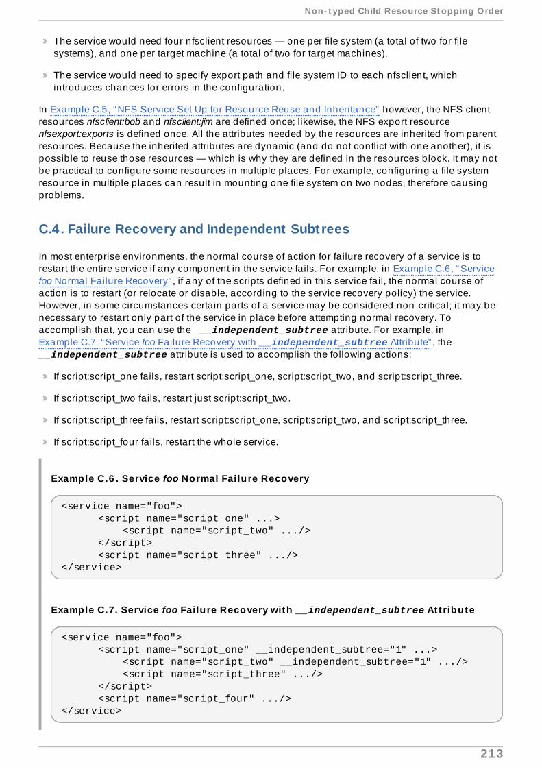
The service would need four nfsclient resources — one per file system (a total of two for filesystems), and one per target machine (a total of two for target machines).
The service would need to specify export path and file system ID to each nfsclient, whichintroduces chances for errors in the configuration.
In Example C.5, “NFS Service Set Up for Resource Reuse and Inheritance” however, the NFS clientresources nfsclient:bob and nfsclient:jim are defined once; likewise, the NFS export resourcenfsexport:exports is defined once. All the attributes needed by the resources are inherited from parentresources. Because the inherited attributes are dynamic (and do not conflict with one another), it ispossible to reuse those resources — which is why they are defined in the resources block. It may notbe practical to configure some resources in multiple places. For example, configuring a file systemresource in multiple places can result in mounting one file system on two nodes, therefore causingproblems.
C.4. Failure Recovery and Independent Subt rees
In most enterprise environments, the normal course of action for failure recovery of a service is torestart the entire service if any component in the service fails. For example, in Example C.6, “Servicefoo Normal Failure Recovery” , if any of the scripts defined in this service fail, the normal course ofaction is to restart (or relocate or disable, according to the service recovery policy) the service.However, in some circumstances certain parts of a service may be considered non-critical; it may benecessary to restart only part of the service in place before attempting normal recovery. Toaccomplish that, you can use the __independent_subtree attribute. For example, inExample C.7, “Service foo Failure Recovery with __independent_subtree Attribute” , the __independent_subtree attribute is used to accomplish the following actions:
If script:script_one fails, restart script:script_one, script:script_two, and script:script_three.
If script:script_two fails, restart just script:script_two.
If script:script_three fails, restart script:script_one, script:script_two, and script:script_three.
If script:script_four fails, restart the whole service.
Example C.6 . Service foo Normal Failure Recovery
<service name="foo"> <script name="script_one" ...> <script name="script_two" .../> </script> <script name="script_three" .../></service>
Example C.7. Service foo Failure Recovery with __independent_subtree At t ribute
<service name="foo"> <script name="script_one" __independent_subtree="1" ...> <script name="script_two" __independent_subtree="1" .../> <script name="script_three" .../> </script> <script name="script_four" .../></service>
Non- t yped Child Resource St opping Order
213

In some circumstances, if a component of a service fails you may want to disable only thatcomponent without disabling the entire service, to avoid affecting other services that use othercomponents of that service. As of the Red Hat Enterprise Linux 6.1 release, you can accomplish thatby using the __independent_subtree="2" attribute, which designates the independent subtreeas non-critical.
Note
You may only use the non-critical flag on singly-referenced resources. The non-critical flagworks with all resources at all levels of the resource tree, but should not be used at the toplevel when defining services or virtual machines.
As of the Red Hat Enterprise Linux 6.1 release, you can set maximum restart and restart expirationson a per-node basis in the resource tree for independent subtrees. To set these thresholds, you canuse the following attributes:
__max_restarts configures the maximum number of tolerated restarts prior to giving up.
__restart_expire_time configures the amount of time, in seconds, after which a restart is nolonger attempted.
C.5. Debugging and Test ing Services and Resource Ordering
You can debug and test services and resource ordering with the rg_test utility. rg_test is acommand-line utility provided by the rgmanager package that is run from a shell or a terminal (it isnot available in Conga). Table C.2, “rg_test Utility Summary” summarizes the actions and syntaxfor the rg_test utility.
Table C.2. rg_test Ut ility Summary
Act ion SyntaxDisplay theresourcerules that rg_testunderstands.
rg_test rules
Test aconfiguration (and/usr/share/cluster) forerrors orredundantresourceagents.
rg_test test /etc/cluster/cluster.conf
Red Hat Ent erprise Linux 6 Clust er Administ rat ion
214

Display thestart andstopordering ofa service.
Display start order:
rg_test noop /etc/cluster/cluster.conf start service servicename
Display stop order:
rg_test noop /etc/cluster/cluster.conf stop service servicename
Explicitlystart or stopa service. Important
Only do this on one node, and always disable the service in rgmanager first.
Start a service:
rg_test test /etc/cluster/cluster.conf start service servicename
Stop a service:
rg_test test /etc/cluster/cluster.conf stop service servicenameCalculateand displaytheresourcetree deltabetween twocluster.conffiles.
rg_test delta cluster.conf file 1 cluster.conf file 2
For example:
rg_test delta /etc/cluster/cluster.conf.bak /etc/cluster/cluster.conf
Act ion Syntax
Non- t yped Child Resource St opping Order
215

Cluster Service Resource Check and Failover Timeout
This appendix describes how rgmanager monitors the status of cluster resources, and how tomodify the status check interval. The appendix also describes the __enforce_timeouts serviceparameter, which indicates that a timeout for an operation should cause a service to fail.
Note
To fully comprehend the information in this appendix, you may require detailed understandingof resource agents and the cluster configuration file, /etc/cluster/cluster.conf. For acomprehensive list and description of cluster.conf elements and attributes, refer to thecluster schema at /usr/share/cluster/cluster.rng , and the annotated schema at /usr/share/doc/cman-X.Y.ZZ/cluster_conf.html (for example /usr/share/doc/cman-3.0.12/cluster_conf.html ).
D.1. Modifying the Resource Status Check Interval
rgmanager checks the status of individual resources, not whole services. Every 10 seconds,rgmanager scans the resource tree, looking for resources that have passed their "status check"interval.
Each resource agent specifies the amount of time between periodic status checks. Each resourceutilizes these timeout values unless explicitly overridden in the cluster.conf file using the special <action> tag:
<action name="status" depth="*" interval="10" />
This tag is a special child of the resource itself in the cluster.conf file. For example, if you had afile system resource for which you wanted to override the status check interval you could specify thefile system resource in the cluster.conf file as follows:
<fs name="test" device="/dev/sdb3"> <action name="status" depth="*" interval="10" /> <nfsexport...> </nfsexport> </fs>
Some agents provide multiple "depths" of checking. For example, a normal file system status check(depth 0) checks whether the file system is mounted in the correct place. A more intensive check isdepth 10, which checks whether you can read a file from the file system. A status check of depth 20checks whether you can write to the file system. In the example given here, the depth is set to *,which indicates that these values should be used for all depths. The result is that the test file systemis checked at the highest-defined depth provided by the resource-agent (in this case, 20) every 10seconds.
D.2. Enforcing Resource T imeouts
There is no timeout for starting, stopping, or failing over resources. Some resources take anindeterminately long amount of time to start or stop. Unfortunately, a failure to stop (including atimeout) renders the service inoperable (failed state). You can, if desired, turn on timeout enforcement
Red Hat Ent erprise Linux 6 Clust er Administ rat ion
216

on each resource in a service individually by adding __enforce_timeouts="1" to the reference inthe cluster.conf file.
The following example shows a cluster service that has been configured with the __enforce_timeouts attribute set for the netfs resource. With this attribute set, then if it takesmore than 30 seconds to unmount the NFS file system during a recovery process the operation willtime out, causing the service to enter the failed state.
</screen><rm> <failoverdomains/> <resources> <netfs export="/nfstest" force_unmount="1" fstype="nfs" host="10.65.48.65" mountpoint="/data/nfstest" name="nfstest_data" options="rw,sync,soft"/> </resources> <service autostart="1" exclusive="0" name="nfs_client_test" recovery="relocate"> <netfs ref="nfstest_data" __enforce_timeouts="1"/> </service></rm>
Clust er Service Resource Check and Failover T imeout
217

Command Line Tools Summary
Table E.1, “Command Line Tool Summary” summarizes preferred command-line tools for configuringand managing the High Availability Add-On. For more information about commands and variables,refer to the man page for each command-line tool.
Table E.1. Command Line Tool Summary
Command Line Tool Used With Purposeccs_config_dump — ClusterConfiguration Dump Tool
Cluster Infrastructure ccs_config_dump generates XMLoutput of running configuration. Therunning configuration is, sometimes,different from the stored configuration onfile because some subsystems store orset some default information into theconfiguration. Those values aregenerally not present on the on-diskversion of the configuration but arerequired at runtime for the cluster to workproperly. For more information about thistool, refer to the ccs_config_dump(8)man page.
ccs_config_validate —Cluster ConfigurationValidation Tool
Cluster Infrastructure ccs_config_validate validates cluster.conf against the schema, cluster.rng (located in /usr/share/cluster/cluster.rngon each node). For more informationabout this tool, refer to theccs_config_validate(8) man page.
clustat — Cluster StatusUtility
High-availabilityService ManagementComponents
The clustat command displays thestatus of the cluster. It showsmembership information, quorum view,and the state of all configured userservices. For more information about thistool, refer to the clustat(8) man page.
clusvcadm — Cluster UserService Administration Utility
High-availabilityService ManagementComponents
The clusvcadm command allows you toenable, disable, relocate, and restarthigh-availability services in a cluster. Formore information about this tool, refer tothe clusvcadm(8) man page.
cman_tool — ClusterManagement Tool
Cluster Infrastructure cman_tool is a program that managesthe CMAN cluster manager. It providesthe capability to join a cluster, leave acluster, kill a node, or change theexpected quorum votes of a node in acluster. For more information about thistool, refer to the cman_tool(8) man page.
fence_tool — Fence Tool Cluster Infrastructure fence_tool is a program used to joinand leave the fence domain. For moreinformation about this tool, refer to thefence_tool(8) man page.
Red Hat Ent erprise Linux 6 Clust er Administ rat ion
218

High Availability LVM (HA-LVM)
The Red Hat High Availability Add-On provides support for high availability LVM volumes (HA-LVM)in a failover configuration. This is distinct from active/active configurations enabled by the ClusteredLogical Volume Manager (CLVM), which is a set of clustering extensions to LVM that allow a cluster ofcomputers to manage shared storage.
When to use CLVM or HA-LVM should be based on the needs of the applications or services beingdeployed.
If the applications are cluster-aware and have been tuned to run simultaneously on multiplemachines at a time, then CLVM should be used. Specifically, if more than one node of your clusterwill require access to your storage which is then shared among the active nodes, then you mustuse CLVM. CLVM allows a user to configure logical volumes on shared storage by locking accessto physical storage while a logical volume is being configured, and uses clustered lockingservices to manage the shared storage. For information on CLVM, and on LVM configuration ingeneral, refer to Logical Volume Manager Administration.
If the applications run optimally in active/passive (failover) configurations where only a singlenode that accesses the storage is active at any one time, you should use High Availability LogicalVolume Management agents (HA-LVM).
Most applications will run better in an active/passive configuration, as they are not designed oroptimized to run concurrently with other instances. Choosing to run an application that is not cluster-aware on clustered logical volumes may result in degraded performance if the logical volume ismirrored. This is because there is cluster communication overhead for the logical volumesthemselves in these instances. A cluster-aware application must be able to achieve performancegains above the performance losses introduced by cluster file systems and cluster-aware logicalvolumes. This is achievable for some applications and workloads more easily than others.Determining what the requirements of the cluster are and whether the extra effort toward optimizing foran active/active cluster will pay dividends is the way to choose between the two LVM variants. Mostusers will achieve the best HA results from using HA-LVM.
HA-LVM and CLVM are similar in the fact that they prevent corruption of LVM metadata and its logicalvolumes, which could otherwise occur if multiple machines where allowed to make overlappingchanges. HA-LVM imposes the restriction that a logical volume can only be activated exclusively; thatis, active on only one machine at a time. This means that only local (non-clustered) implementationsof the storage drivers are used. Avoiding the cluster coordination overhead in this way increasesperformance. CLVM does not impose these restrictions - a user is free to activate a logical volume onall machines in a cluster; this forces the use of cluster-aware storage drivers, which allow for cluster-aware file systems and applications to be put on top.
HA-LVM can be setup to use one of two methods for achieving its mandate of exclusive logicalvolume activation.
The preferred method uses CLVM, but it will only ever activate the logical volumes exclusively.This has the advantage of easier setup and better prevention of administrative mistakes (likeremoving a logical volume that is in use). In order to use CLVM, the High Availability Add-On andResilient Storage Add-On software, including the clvmd daemon, must be running.
The procedure for configuring HA-LVM using this method is described in Section F.1,“Configuring HA-LVM Failover with CLVM (preferred)” .
The second method uses local machine locking and LVM "tags". This method has the advantageof not requiring any LVM cluster packages; however, there are more steps involved in setting it upand it does not prevent an administrator from mistakenly removing a logical volume from a nodein the cluster where it is not active. The procedure for configuring HA-LVM using this method is
High Availabilit y LVM (HA- LVM)
219
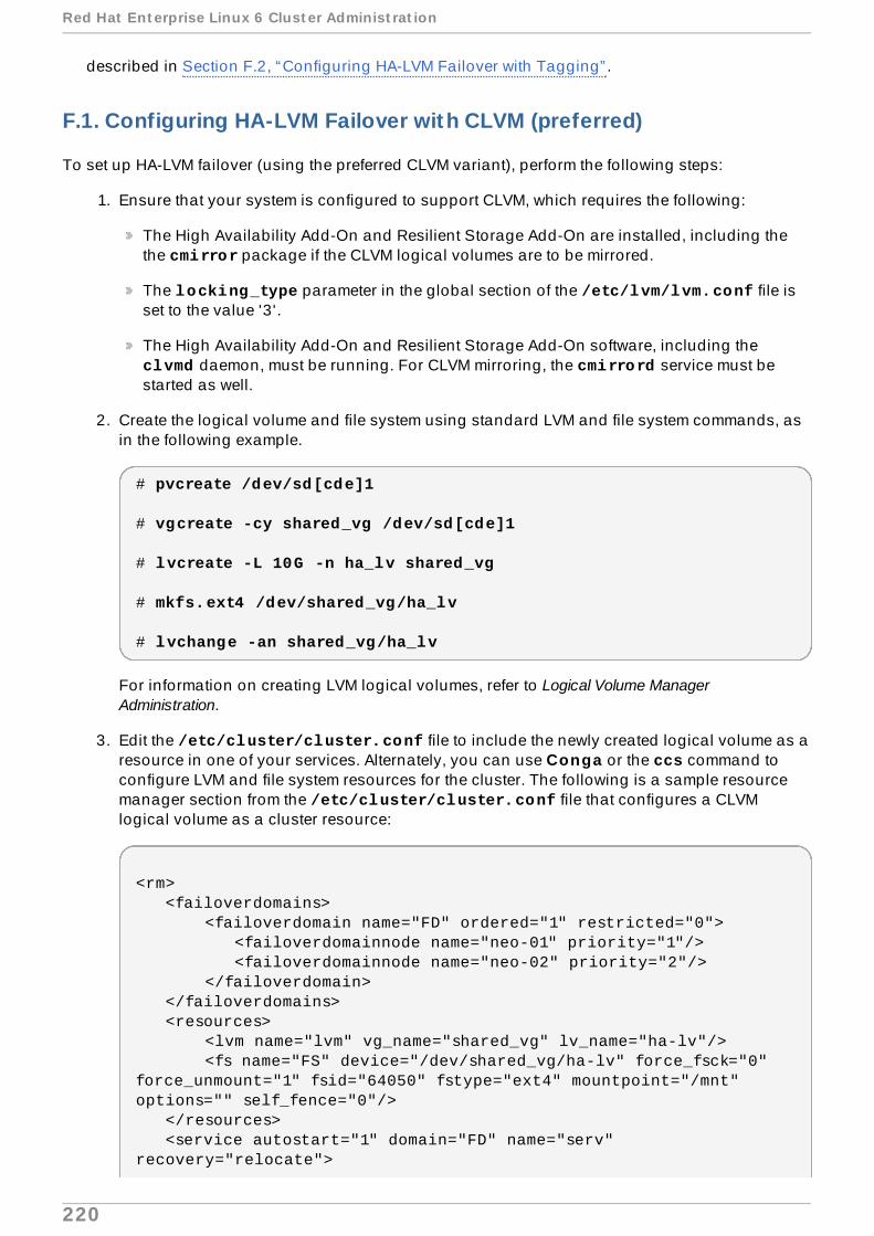
described in Section F.2, “Configuring HA-LVM Failover with Tagging” .
F.1. Configuring HA-LVM Failover with CLVM (preferred)
To set up HA-LVM failover (using the preferred CLVM variant), perform the following steps:
1. Ensure that your system is configured to support CLVM, which requires the following:
The High Availability Add-On and Resilient Storage Add-On are installed, including thethe cmirror package if the CLVM logical volumes are to be mirrored.
The locking_type parameter in the global section of the /etc/lvm/lvm.conf file isset to the value '3'.
The High Availability Add-On and Resilient Storage Add-On software, including the clvmd daemon, must be running. For CLVM mirroring, the cmirrord service must bestarted as well.
2. Create the logical volume and file system using standard LVM and file system commands, asin the following example.
# pvcreate /dev/sd[cde]1
# vgcreate -cy shared_vg /dev/sd[cde]1
# lvcreate -L 10G -n ha_lv shared_vg
# mkfs.ext4 /dev/shared_vg/ha_lv
# lvchange -an shared_vg/ha_lv
For information on creating LVM logical volumes, refer to Logical Volume ManagerAdministration.
3. Edit the /etc/cluster/cluster.conf file to include the newly created logical volume as aresource in one of your services. Alternately, you can use Conga or the ccs command toconfigure LVM and file system resources for the cluster. The following is a sample resourcemanager section from the /etc/cluster/cluster.conf file that configures a CLVMlogical volume as a cluster resource:
<rm> <failoverdomains> <failoverdomain name="FD" ordered="1" restricted="0"> <failoverdomainnode name="neo-01" priority="1"/> <failoverdomainnode name="neo-02" priority="2"/> </failoverdomain> </failoverdomains> <resources> <lvm name="lvm" vg_name="shared_vg" lv_name="ha-lv"/> <fs name="FS" device="/dev/shared_vg/ha-lv" force_fsck="0" force_unmount="1" fsid="64050" fstype="ext4" mountpoint="/mnt" options="" self_fence="0"/> </resources> <service autostart="1" domain="FD" name="serv" recovery="relocate">
Red Hat Ent erprise Linux 6 Clust er Administ rat ion
220

<lvm ref="lvm"/> <fs ref="FS"/> </service></rm>
F.2. Configuring HA-LVM Failover with Tagging
To set up HA-LVM failover by using tags in the /etc/lvm/lvm.conf file, perform the followingsteps:
1. Ensure that the locking_type parameter in the global section of the /etc/lvm/lvm.conf file is set to the value '1'.
2. Create the logical volume and file system using standard LVM and file system commands, asin the following example.
# pvcreate /dev/sd[cde]1
# vgcreate shared_vg /dev/sd[cde]1
# lvcreate -L 10G -n ha_lv shared_vg
# mkfs.ext4 /dev/shared_vg/ha_lv
For information on creating LVM logical volumes, refer to Logical Volume ManagerAdministration.
3. Edit the /etc/cluster/cluster.conf file to include the newly created logical volume as aresource in one of your services. Alternately, you can use Conga or the ccs command toconfigure LVM and file system resources for the cluster. The following is a sample resourcemanager section from the /etc/cluster/cluster.conf file that configures a CLVMlogical volume as a cluster resource:
<rm> <failoverdomains> <failoverdomain name="FD" ordered="1" restricted="0"> <failoverdomainnode name="neo-01" priority="1"/> <failoverdomainnode name="neo-02" priority="2"/> </failoverdomain> </failoverdomains> <resources> <lvm name="lvm" vg_name="shared_vg" lv_name="ha_lv"/> <fs name="FS" device="/dev/shared_vg/ha_lv" force_fsck="0" force_unmount="1" fsid="64050" fstype="ext4" mountpoint="/mnt" options="" self_fence="0"/> </resources> <service autostart="1" domain="FD" name="serv" recovery="relocate"> <lvm ref="lvm"/> <fs ref="FS"/> </service></rm>
High Availabilit y LVM (HA- LVM)
221

Note
If there are multiple logical volumes in the volume group, then the logical volume name(lv_name) in the lvm resource should be left blank or unspecified. Also note that inan HA-LVM configuration, a volume group may be used by only a single service.
4. Edit the volume_list field in the /etc/lvm/lvm.conf file. Include the name of your rootvolume group and your hostname as listed in the /etc/cluster/cluster.conf filepreceded by @. The hostname to include here is the machine on which you are editing the lvm.conf file, not any remote hostname. Note that this string MUST match the node namegiven in the cluster.conf file. Below is a sample entry from the /etc/lvm/lvm.conf file:
volume_list = [ "VolGroup00", "@neo-01" ]
This tag will be used to activate shared VGs or LVs. DO NOT include the names of anyvolume groups that are to be shared using HA-LVM.
5. Update the initramfs device on all your cluster nodes:
# dracut -H -f /boot/initramfs-$(uname -r).img $(uname -r)
6. Reboot all nodes to ensure the correct initrd device is in use.
Red Hat Ent erprise Linux 6 Clust er Administ rat ion
222

Revision History
Revision 7.0-13 Wed Oct 8 2014 Steven LevineVersion for 6.6 GA release
Revision 7.0-12 Fri Sep 26 2014 Steven LevineResolves: #11288810Adds SCSI fence note
Revision 7.0-11 Thu Aug 7 2014 Steven LevineVersion for 6.6 Beta release
Revision 7.0-10 Mon Jul 28 2014 Steven LevineLatest draft for 6.6 release
Resolves: #1107601, #1098288, #969087, #987070, #1010049, #1081182, #1099579, #1062178Small technical and editorial corrections and clarifications.
Resolves: #1092726, #1093131, #1061769, #1081215, #1081222Documents new resource agent parameters
Resolves: #1092730, #1081143, #1081147Documents new fence agent parameters
Resolves: #1035013Clarifies that automatic updates must be disabled for clusters
Resolves: #1124063Adds parameter table for Bind Mount resource agent
Resolves: #1081260Documents new ccs start and stop options
Resolves: #856311References fence_check man page
Resolves: #987587Adds parameter table for Named (Bind 9) resource agent
Resolves: #1081175Adds parameter table for kdump fence agent
Resolves: #1081181Documents addition of sorting capabilities to cluster resource list on luci
Resolves: #1081222Documents addition of sorting capabilities to cluster resource list on luci
Resolves: #1094508Clarifies description of nfsexport resource agent configuration
Revision 6 .0-21 Wed Nov 13 2013 Steven Levine
Revision Hist ory
223

Version for 6.5 GA release
Revision 6 .0-20 Wed Nov 6 2013 Steven LevineResolves: #986462Updates oracledb resource table.
Revision 6 .0-16 Tue Oct 29 2013 Steven LevineResolves: #1021045Corrects example of iptables rule.
Revision 6 .0-15 Fri Sep 27 2013 Steven LevineVersion for 6.5 Beta release
Revision 6 .0-12 Thu Sep 26 2013 Steven LevineResolves: #884758, #893575, #969525, #969139, #987151, #987623Small updates to fence device parameter tables.
Resolves: #901637, #983739, 986462Small updates to resource parameter tables.
Resolves: #633495Documents configuration of nfsexport and nfsserver resources.
Resolves: #852966, #975512, #977194, #991297, #874211, #908328, #919600,#955405, #972521,#986474, #987135, #698454, #967986Small corrections and clarifications throughout document.
Revision 6 .0-3 Thu Sep 05 2013 Steven LevineMajor review revision for all 6.5 BZs.
Revision 6 .0-2 Fri Jun 14 2013 Steven LevineAdding section on configuring nfsserver and nfsexport.
Revision 6 .0-1 Thu Jun 13 2013 Steven LevineUpdating cluster update procedures and qdisk considerations.
Revision 5.0-25 Mon Feb 18 2013 Steven LevineVersion for 6.4 GA release
Revision 5.0-23 Wed Jan 30 2013 Steven LevineResolves: 901641Corrects and clarifies iptables rules.
Revision 5.0-22 Tue Jan 29 2013 Steven LevineResolves: 788636Documents RRP configuration through ccs command.
Resolves: 789010Document RRP configuration in the cluster.conf file.
Revision 5.0-20 Fri Jan 18 2013 Steven Levine
Red Hat Ent erprise Linux 6 Clust er Administ rat ion
224

Resolves: 894097Removes advice to ensure you are not using VLAN tagging.
Resolves: 845365Indicates that bonding modes 0 and 2 are now supported.
Revision 5.0-19 Thu Jan 17 2013 Steven LevineResolves: 896234Clarifies terminology of cluster node references.
Revision 5.0-16 Mon Nov 26 2012 Steven LevineVersion for 6.4 Beta release
Revision 5.0-15 Wed Nov 20 2012 Steven LevineResolves: 838988Documents nfsrestart attribute for file system resource agents.
Resolves: 843169Documents IBM iPDU fence agent.
Resolves: 846121Documents Eaton Network Power Controller (SNMP Interface) fence agent.
Resolves: 856834Documents HP Bladesystem fence agent.
Resolves: 865313Documents NFS Server resource agent.
Resolves: 862281Clarifies which ccs commands overwrite previous settings.
Resolves: 846205Documents iptables firewall filtering for igmp component.
Resolves: 857172Documents ability to remove users from luci.
Resolves: 857165Documents the privilege level parameter of the IPMI fence agent.
Resolves: 840912Clears up formatting issue with resource parameter table.
Resolves: 849240, 870292Clarifies installation procedure.
Resolves: 871165Clarifies description of IP address parameter in description of IP address resource agent.
Resolves: 845333, 869039, 856681Fixes small typographical errors and clarifies small technical ambiguities.
Revision Hist ory
225

Revision 5.0-12 Thu Nov 1 2012 Steven LevineAdded newly-supported fence agents.
Revision 5.0-7 Thu Oct 25 2012 Steven LevineAdded section on override semantics.
Revision 5.0-6 Tue Oct 23 2012 Steven LevineFixed default value of Post Join Delay.
Revision 5.0-4 Tue Oct 16 2012 Steven LevineAdded description of NFS server resource.
Revision 5.0-2 Thu Oct 11 2012 Steven LevineUpdates to Conga descriptions.
Revision 5.0-1 Mon Oct 8 2012 Steven LevineClarifying ccs semantics
Revision 4 .0-5 Fri Jun 15 2012 Steven LevineVersion for 6.3 GA release
Revision 4 .0-4 Tue Jun 12 2012 Steven LevineResolves: 830148Ensures consistency of port number examples for luci.
Revision 4 .0-3 Tue May 21 2012 Steven LevineResolves: 696897Adds cluster.conf parameter information to tables of fence device parameters and resourceparameters.
Resolves: 811643Adds procedure for restoring a luci database on a separate machine.
Revision 4 .0-2 Wed Apr 25 2012 Steven LevineResolves: 815619Removes warning about using UDP Unicast with GFS2 file systems.
Revision 4 .0-1 Fri Mar 30 2012 Steven Levine
Red Hat Ent erprise Linux 6 Clust er Administ rat ion
226

Resolves: 771447, 800069, 800061Updates documentation of luci to be consistent with Red Hat Enterprise Linux 6.3 version.
Resolves: 712393Adds information on capturing an application core for RGManager.
Resolves: 800074Documents condor resource agent.
Resolves: 757904Documents luci configuration backup and restore.
Resolves: 772374Adds section on managing virtual machines in a cluster.
Resolves: 712378Adds documentation for HA-LVM configuration.
Resolves: 712400Documents debug options.
Resolves: 751156Documents new fence_ipmilan parameter.
Resolves: 721373Documents which configuration changes require a cluster restart.
Revision 3.0-5 Thu Dec 1 2011 Steven LevineRelease for GA of Red Hat Enterprise Linux 6.2
Resolves: 755849Corrects monitor_link parameter example.
Revision 3.0-4 Mon Nov 7 2011 Steven LevineResolves: 749857Adds documentation for RHEV-M REST API fence device.
Revision 3.0-3 Fri Oct 21 2011 Steven LevineResolves: #747181, #747182, #747184, #747185, #747186, #747187, #747188, #747189, #747190,#747192Corrects typographical errors and ambiguities found during documentation QE review for Red HatEnterprise Linux 6.2.
Revision 3.0-2 Fri Oct 7 2011 Steven LevineResolves: #743757Corrects reference to supported bonding mode in troubleshooting section.
Revision 3.0-1 Wed Sep 28 2011 Steven Levine
Revision Hist ory
227

Initial revision for Red Hat Enterprise Linux 6.2 Beta release
Resolves: #739613Documents support for new ccs options to display available fence devices and available services.
Resolves: #707740Documents updates to the Conga interface and documents support for setting user permissions toadminister Conga.
Resolves: #731856Documents supports for configuring luci by means of the /etc/sysconfig/luci file.
Resolves: #736134Documents support for UDPU transport.
Resolves: #736143Documents support for clustered Samba.
Resolves: #617634Documents how to configure the only IP address luci is served at.
Resolves: #713259Documents support for fence_vmware_soap agent.
Resolves: #721009Provides link to Support Essentials article.
Resolves: #717006Provides information on allowing multicast traffic through the iptables firewall.
Resolves: #717008Provides information about cluster service status check and failover timeout.
Resolves: #711868Clarifies description of autostart.
Resolves: #728337Documents procedure for adding vm resources with the ccs command.
Resolves: #725315, #733011, #733074, #733689Corrects small typographical errors.
Revision 2.0-1 Thu May 19 2011 Steven Levine
Red Hat Ent erprise Linux 6 Clust er Administ rat ion
228
Initial revision for Red Hat Enterprise Linux 6.1
Resolves: #671250Documents support for SNMP traps.
Resolves: #659753Documents ccs command.
Resolves: #665055Updates Conga documentation to reflect updated display and feature support.
Resolves: #680294Documents need for password access for ricci agent.
Resolves: #687871Adds chapter on troubleshooting.
Resolves: #673217Fixes typographical error.
Resolves: #675805Adds reference to cluster.conf schema to tables of HA resource parameters.
Resolves: #672697Updates tables of fence device parameters to include all currently supported fencing devices.
Resolves: #677994Corrects information for fence_ilo fence agent parameters.
Resolves: #629471Adds technical note about setting consensus value in a two-node cluster.
Resolves: #579585Updates section on upgrading Red Hat High Availability Add-On Software.
Resolves: #643216Clarifies small issues throughout document.
Resolves: #643191Provides improvements and corrections for the luci documentation.
Resolves: #704539Updates the table of Virtual Machine resource parameters.
Revision 1.0-1 Wed Nov 10 2010 Paul KennedyInitial release for Red Hat Enterprise Linux 6
Index
AACPI
Revision Hist ory
229

- configuring, Configuring ACPI For Use with Integrated Fence Devices
APC power switch over SNMP fence device , Fence Device Parameters
APC power switch over telnet /SSH fence device , Fence Device Parameters
Bbehavior, HA resources, HA Resource Behavior
Brocade fabric switch fence device , Fence Device Parameters
CCISCO MDS fence device , Fence Device Parameters
Cisco UCS fence device , Fence Device Parameters
cluster- administration, Before Configuring the Red Hat High Availability Add-On, ManagingRed Hat High Availability Add-On With Conga, Managing Red Hat High AvailabilityAdd-On With ccs, Managing Red Hat High Availability Add-On With Command LineTools- diagnosing and correcting problems, Diagnosing and Correcting Problems in aCluster, Diagnosing and Correcting Problems in a Cluster- starting, stopping, restarting, Starting and Stopping the Cluster Software
cluster administ rat ion, Before Conf iguring the Red Hat High Availab ility Add-On,Managing Red Hat High Availab ility Add-On With Conga, Managing Red Hat HighAvailab ility Add-On With ccs, Managing Red Hat High Availab ility Add-On WithCommand Line Tools
- adding cluster node, Adding a Member to a Running Cluster, Adding a Member to aRunning Cluster- compatible hardware, Compatible Hardware- configuration validation, Configuration Validation- configuring ACPI, Configuring ACPI For Use with Integrated Fence Devices- configuring iptables, Enabling IP Ports- considerations for using qdisk, Considerations for Using Quorum Disk- considerations for using quorum disk, Considerations for Using Quorum Disk- deleting a cluster, Starting, Stopping, Restarting, and Deleting Clusters- deleting a node from the configuration; adding a node to the configuration , Deletingor Adding a Node- diagnosing and correcting problems in a cluster, Diagnosing and CorrectingProblems in a Cluster, Diagnosing and Correcting Problems in a Cluster- displaying HA services with clustat, Displaying HA Service Status with clustat- enabling IP ports, Enabling IP Ports- general considerations, General Configuration Considerations- joining a cluster, Causing a Node to Leave or Join a Cluster, Causing a Node toLeave or Join a Cluster- leaving a cluster, Causing a Node to Leave or Join a Cluster, Causing a Node toLeave or Join a Cluster- managing cluster node, Managing Cluster Nodes, Managing Cluster Nodes- managing high-availability services, Managing High-Availability Services,Managing High-Availability Services- managing high-availability services, freeze and unfreeze, Managing HA Serviceswith clusvcadm, Considerations for Using the Freeze and Unfreeze Operations- network switches and multicast addresses, Multicast Addresses- NetworkManager, Considerations for NetworkManager- rebooting cluster node, Rebooting a Cluster Node- removing cluster node, Deleting a Member from a Cluster
Red Hat Ent erprise Linux 6 Clust er Administ rat ion
230
- restarting a cluster, Starting, Stopping, Restarting, and Deleting Clusters- ricci considerations, Considerations for ricci- SELinux, Red Hat High Availability Add-On and SELinux- starting a cluster, Starting, Stopping, Restarting, and Deleting Clusters, Starting andStopping a Cluster- starting, stopping, restarting a cluster, Starting and Stopping the Cluster Software- stopping a cluster, Starting, Stopping, Restarting, and Deleting Clusters, Startingand Stopping a Cluster- updating a cluster configuration using cman_tool version -r, Updating aConfiguration Using cman_tool version -r- updating a cluster configuration using scp, Updating a Configuration Using scp- updating configuration, Updating a Configuration- virtual machines, Configuring Virtual Machines in a Clustered Environment
cluster conf igurat ion, Conf iguring Red Hat High Availab ility Add-On With Conga,Conf iguring Red Hat High Availab ility Add-On With the ccs Command, Conf iguringRed Hat High Availab ility Manually
- deleting or adding a node, Deleting or Adding a Node- updating, Updating a Configuration
cluster resource relat ionships, Parent , Child , and Sib ling Relat ionships AmongResources
cluster resource status check, Cluster Service Resource Check and FailoverTimeout
cluster resource types, Considerat ions for Conf iguring HA Services
cluster service managers- configuration, Adding a Cluster Service to the Cluster, Adding a Cluster Service tothe Cluster, Adding a Cluster Service to the Cluster
cluster services, Adding a Cluster Service to the Cluster, Adding a Cluster Serviceto the Cluster, Adding a Cluster Service to the Cluster
- (see also adding to the cluster configuration)
cluster sof tware- configuration, Configuring Red Hat High Availability Add-On With Conga,Configuring Red Hat High Availability Add-On With the ccs Command, ConfiguringRed Hat High Availability Manually
conf igurat ion- HA service, Considerations for Configuring HA Services
Conf iguring High Availab ility LVM, High Availab ility LVM (HA-LVM)
Conga- accessing, Configuring Red Hat High Availability Add-On Software
consensus value, The consensus Value for to tem in a Two-Node Cluster
DDell DRAC 5 fence device , Fence Device Parameters
Dell iDRAC fence device , Fence Device Parameters
EEaton network power switch, Fence Device Parameters
Index
231

Egenera BladeFrame fence device , Fence Device Parameters
ePowerSwitch fence device , Fence Device Parameters
Ffailover t imeout , Cluster Service Resource Check and Failover T imeout
features, new and changed, New and Changed Features
feedback, Feedback
fence agent- fence_apc, Fence Device Parameters- fence_apc_snmp, Fence Device Parameters- fence_bladecenter, Fence Device Parameters- fence_brocade, Fence Device Parameters- fence_cisco_mds, Fence Device Parameters- fence_cisco_ucs, Fence Device Parameters- fence_drac5, Fence Device Parameters- fence_eaton_snmp, Fence Device Parameters- fence_egenera, Fence Device Parameters- fence_eps, Fence Device Parameters- fence_hpblade, Fence Device Parameters- fence_ibmblade, Fence Device Parameters- fence_idrac, Fence Device Parameters- fence_ifmib, Fence Device Parameters- fence_ilo, Fence Device Parameters- fence_ilo2, Fence Device Parameters- fence_ilo3, Fence Device Parameters- fence_ilo4, Fence Device Parameters- fence_ilo_mp, Fence Device Parameters- fence_imm, Fence Device Parameters- fence_intelmodular, Fence Device Parameters- fence_ipdu, Fence Device Parameters- fence_ipmilan, Fence Device Parameters- fence_kdump, Fence Device Parameters- fence_rhevm, Fence Device Parameters- fence_rsb, Fence Device Parameters- fence_scsi, Fence Device Parameters- fence_virt, Fence Device Parameters- fence_vmware_soap, Fence Device Parameters- fence_wti, Fence Device Parameters
fence device- APC power switch over SNMP, Fence Device Parameters- APC power switch over telnet/SSH, Fence Device Parameters- Brocade fabric switch, Fence Device Parameters- Cisco MDS, Fence Device Parameters- Cisco UCS, Fence Device Parameters- Dell DRAC 5, Fence Device Parameters- Dell iDRAC, Fence Device Parameters- Eaton network power switch, Fence Device Parameters- Egenera BladeFrame, Fence Device Parameters- ePowerSwitch, Fence Device Parameters- Fence virt, Fence Device Parameters- Fujitsu Siemens Remoteview Service Board (RSB), Fence Device Parameters- HP BladeSystem, Fence Device Parameters- HP iLO, Fence Device Parameters
Red Hat Ent erprise Linux 6 Clust er Administ rat ion
232

- HP iLO MP, Fence Device Parameters- HP iLO2, Fence Device Parameters- HP iLO3, Fence Device Parameters- HP iLO4, Fence Device Parameters- IBM BladeCenter, Fence Device Parameters- IBM BladeCenter SNMP, Fence Device Parameters- IBM Integrated Management Module, Fence Device Parameters- IBM iPDU, Fence Device Parameters- IF MIB, Fence Device Parameters- Intel Modular, Fence Device Parameters- IPMI LAN, Fence Device Parameters- RHEV-M REST API, Fence Device Parameters- SCSI fencing, Fence Device Parameters- VMware (SOAP interface), Fence Device Parameters- WTI power switch, Fence Device Parameters
Fence virt fence device , Fence Device Parameters
fence_apc fence agent , Fence Device Parameters
fence_apc_snmp fence agent , Fence Device Parameters
fence_bladecenter fence agent , Fence Device Parameters
fence_brocade fence agent , Fence Device Parameters
fence_cisco_mds fence agent , Fence Device Parameters
fence_cisco_ucs fence agent , Fence Device Parameters
fence_drac5 fence agent , Fence Device Parameters
fence_eaton_snmp fence agent , Fence Device Parameters
fence_egenera fence agent , Fence Device Parameters
fence_eps fence agent , Fence Device Parameters
fence_hpblade fence agent , Fence Device Parameters
fence_ibmblade fence agent , Fence Device Parameters
fence_idrac fence agent , Fence Device Parameters
fence_ifmib fence agent , Fence Device Parameters
fence_ilo fence agent , Fence Device Parameters
fence_ilo2 fence agent , Fence Device Parameters
fence_ilo3 fence agent , Fence Device Parameters
fence_ilo4 fence agent , Fence Device Parameters
fence_ilo_mp fence agent , Fence Device Parameters
fence_imm fence agent , Fence Device Parameters
fence_intelmodular fence agent , Fence Device Parameters
fence_ipdu fence agent , Fence Device Parameters
fence_ipmilan fence agent , Fence Device Parameters
fence_kdump fence agent , Fence Device Parameters
fence_rhevm fence agent , Fence Device Parameters
fence_rsb fence agent , Fence Device Parameters
fence_scsi fence agent , Fence Device Parameters
fence_virt fence agent , Fence Device Parameters
fence_vmware_soap fence agent , Fence Device Parameters
Index
233

fence_wt i fence agent , Fence Device Parameters
Fujitsu Siemens Remoteview Service Board (RSB) fence device, Fence DeviceParameters
Ggeneral
- considerations for cluster administration, General Configuration Considerations
HHA service conf igurat ion
- overview, Considerations for Configuring HA Services
hardware- compatible, Compatible Hardware
HP Bladesystem fence device , Fence Device Parameters
HP iLO fence device, Fence Device Parameters
HP iLO MP fence device , Fence Device Parameters
HP iLO2 fence device, Fence Device Parameters
HP iLO3 fence device, Fence Device Parameters
HP iLO4 fence device, Fence Device Parameters
IIBM BladeCenter fence device , Fence Device Parameters
IBM BladeCenter SNMP fence device , Fence Device Parameters
IBM Integrated Management Module fence device , Fence Device Parameters
IBM iPDU fence device , Fence Device Parameters
IF MIB fence device , Fence Device Parameters
integrated fence devices- configuring ACPI, Configuring ACPI For Use with Integrated Fence Devices
In tel Modular fence device , Fence Device Parameters
int roduct ion, In t roduct ion- other Red Hat Enterprise Linux documents, Introduction
IP ports- enabling, Enabling IP Ports
IPMI LAN fence device , Fence Device Parameters
iptables- configuring, Enabling IP Ports
ip tables f irewall, Conf iguring the ip tables Firewall to Allow Cluster Components
LLVM, High Availab ility, High Availab ility LVM (HA-LVM)
Mmult icast addresses
Red Hat Ent erprise Linux 6 Clust er Administ rat ion
234

- considerations for using with network switches and multicast addresses, MulticastAddresses
mult icast t raf f ic, enabling, Conf iguring the ip tables Firewall to Allow ClusterComponents
NNetworkManager
- disable for use with cluster, Considerations for NetworkManager
nfsexport resource, conf iguring, Conf iguring nfsexport and nfsserver Resources
nfsserver resource, conf iguring, Conf iguring nfsexport and nfsserver Resources
Ooverview
- features, new and changed, New and Changed Features
Pparameters, fence device, Fence Device Parameters
parameters, HA resources, HA Resource Parameters
Qqdisk
- considerations for using, Considerations for Using Quorum Disk
quorum disk- considerations for using, Considerations for Using Quorum Disk
Rrelat ionships
- cluster resource, Parent, Child, and Sibling Relationships Among Resources
RHEV-M REST API fence device , Fence Device Parameters
ricci- considerations for cluster administration, Considerations for ricci
SSCSI fencing, Fence Device Parameters
SELinux- configuring, Red Hat High Availability Add-On and SELinux
status check, cluster resource, Cluster Service Resource Check and FailoverTimeout
Ttab les
- fence devices, parameters, Fence Device Parameters- HA resources, parameters, HA Resource Parameters
t imeout failover, Cluster Service Resource Check and Failover T imeout
tools, command line, Command Line Tools Summary
Index
235

to tem tag- consensus value, The consensus Value for totem in a Two-Node Cluster
t roubleshoot ing- diagnosing and correcting problems in a cluster, Diagnosing and CorrectingProblems in a Cluster, Diagnosing and Correcting Problems in a Cluster
types- cluster resource, Considerations for Configuring HA Services
Vvalidat ion
- cluster configuration, Configuration Validation
virtual machines, in a cluster, Conf iguring Virtual Machines in a ClusteredEnvironment
VMware (SOAP interface) fence device , Fence Device Parameters
WWTI power switch fence device , Fence Device Parameters
Red Hat Ent erprise Linux 6 Clust er Administ rat ion
236


