Redundant VFDs and Fan Arrays in Critical Operations Maintaining Controlled Air-flow in a Critical Operation yaskawa.com Author: Shane King, Building Automation Application Engineer, Yaskawa America, Inc.
Transcript
Redundant VFDs and Fan Arrays in Critical OperationsMaintaining Controlled Air-flow in a Critical Operation
yaskawa.com Author: Shane King, Building Automation Application Engineer, Yaskawa America, Inc.
IntroductionWhat is the best way to power a fan array in a critical operation? For those who may not know what a fan array is, a fan array is exactly what it sounds like - a series of smaller fans designed to carry the load once handled by a single larger fan.
Advantages of Fan ArraysThere are several advantages of using a fan array over a single fan.
The first advantage is that a motor/fan failure will not shut down the system, which can be extremely important in critical operations.
Second, smaller and lighter wheels and motors are easier to replace. Using six 15HP motors in lieu of one 100HP motor means when a motor fails, you’re only replacing a 15HP motor – cheaper, and physically easier to replace that one 50HP motor.
More of an “up front” advantage is that shorter fan section lengths can be achieved when using a fan array verses one large fan. Also, a greater operating spectrum can be achieved, which will be particularly useful at low flow and partial loads.
Powering Fan ArraysSo, what is the best way to power a fan array?
Considering we’re dealing with a critical operation that likely requires a speed range a bit more adjustable than 0Hz or 60Hz, this paper will focus on methods involving VFD power. While “VFD power” may sound like enough to be a final answer, it isn’t. There are still several factors to consider.
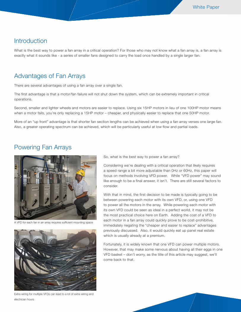
With that in mind, the first decision to be made is typically going to be between powering each motor with its own VFD, or, using one VFD to power all the motors in the array. While powering each motor with its own VFD could be seen as ideal in a perfect world, it may not be the most practical choice here on Earth. Adding the cost of a VFD to each motor in a fan array could quickly prove to be cost-prohibitive, immediately negating the “cheaper and easier to replace” advantages previously discussed. Also, it would quickly eat up panel real estate which is usually already at a premium.
Fortunately, it is widely known that one VFD can power multiple motors. However, that may make some nervous about having all their eggs in one VFD basket – don’t worry, as the title of this article may suggest, we’ll come back to that.
White Paper
A VFD for each fan in an array requires sufficient mounting space
Extra wiring for multiple VFDs can lead to a lot of extra wiring and
electrician hours
White Papers
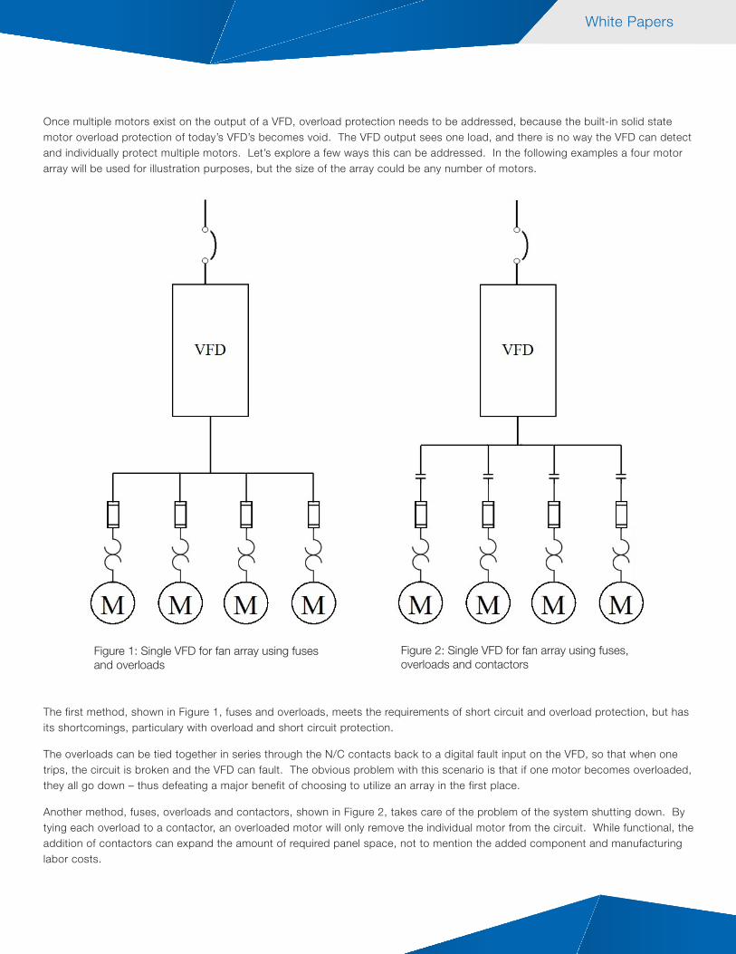
Once multiple motors exist on the output of a VFD, overload protection needs to be addressed, because the built-in solid state motor overload protection of today’s VFD’s becomes void. The VFD output sees one load, and there is no way the VFD can detect and individually protect multiple motors. Let’s explore a few ways this can be addressed. In the following examples a four motor array will be used for illustration purposes, but the size of the array could be any number of motors.
The first method, shown in Figure 1, fuses and overloads, meets the requirements of short circuit and overload protection, but has its shortcomings, particulary with overload and short circuit protection.
The overloads can be tied together in series through the N/C contacts back to a digital fault input on the VFD, so that when one trips, the circuit is broken and the VFD can fault. The obvious problem with this scenario is that if one motor becomes overloaded, they all go down – thus defeating a major benefit of choosing to utilize an array in the first place.
Another method, fuses, overloads and contactors, shown in Figure 2, takes care of the problem of the system shutting down. By tying each overload to a contactor, an overloaded motor will only remove the individual motor from the circuit. While functional, the addition of contactors can expand the amount of required panel space, not to mention the added component and manufacturing labor costs.
Figure 1: Single VFD for fan array using fuses and overloads
Figure 2: Single VFD for fan array using fuses, overloads and contactors
White Paper
A third method, shown in figure 3, MMP’s (Manual Motor Protector), also has the built-in ability to remove the overloaded motor from the circuit, allowing the remaining motors to continue operation unimpeded.
Many consider this to be the ideal method of choice when considering cost, panel space, and overall component count. The advantage of MMP’s is the combination of magnetic short-circuit trip protection and adjustable motor overload protection that they provide per NEC 430.32. This makes them most beneficial for multiple motor operation on the output of a VFD, however, some of that advantage is lost when the VFD package incorporates an across the line bypass.
A downside to MMP’s is that an MMP cannot provide motor branch circuit short-circuit and ground fault protection. While this isn’t a problem when it is being utilized as a downstream device, it does pose a problem in an across the line bypass situation. In that event, shown in Figure 4, fuses are still required to meet UL.
Figure 3 : Single VFD for fan array using MMP’s Figure 4: Single VFD for fan array with bypass, using MMP’s and fuses
Redundant VFD Packages as a SolutionMany critical operations today involving fan arrays are using redundant VFD packages, thus replacing the across the line option in a typical VFD bypass package with another VFD, illustrated in Figure 5.
With redundant VFD packages, we have the ideal scenario for employing MMP’s for overload protection in our fan array application. With no across the line bypass option, the need for fuses is eliminated.
A redundant VFD cabinet with built-in motor protection for fan arrays can already be pretty crowded with 3 fuses for each motor taking residence in the panel, and can mean the difference in whether or not an enclosure size increase is required.
White Paper
Figure 5: Redundant VFD package for fan array using MMP’s
DS2
S3 S2
DS4
DS3
DRIVE AFAULT
S1
DS1
DS5
EXTERNAL DRIVE BFAULT
DRIVE BRUN
FAULT
RUNDRIVE A
FAULT XFER OFF
MAN AUTO HAND AUTOAUTO
DRV A DRV B
DRIVE BDRIVE A
Z1000 Z1000
DS2
S3 S2
DS4
DS3
DRIVE AFAULT
S1
DS1
DS5
EXTERNAL DRIVE BFAULT
DRIVE BRUN
FAULT
RUNDRIVE A
FAULT XFER OFF
MAN AUTO HAND AUTOAUTO
DRV A DRV B
VFD AZ100040 HP
VFD BZ100040 HP
VFD AInput Fuses
VFD BInput Fuses
InputCircuitBreaker
Inside the Redundant Drive Package
Redundant Drive Package Controls
ConclusionIf you’ve got a critical operation, and have chosen to go the route of fan array, you have several options. However, it would definitely be a good idea to consider a redundant VFD package and MMP’s.
You’ll be making a wise choice that saves up front costs, panel space, maintenance costs and most importantly provides rock solid reliability for many years (possibly decades) to come.
White Paper
Yaskawa America, Inc. Drives & Motion Division yaskawa.com