36
Ref f N3S Publi¬ cations NAT L INST. OF STAND & TECH R LC A111Q4 136^45 yf -i -t. Of NBS HANDBOOK 129 U51 no,129 1979
Ref f N3S Publi¬ cations
NAT L INST. OF STAND & TECH R LC
A111Q4 136^45
yf -i -t.
Of
NBS HANDBOOK 129
U51 no,129 1979

NATIONAL BUREAU OF STANDARDS
The National Bureau of Standards' was established by an act of Congress on March 3, 1901. The Bureau’s overall goal is to strengthen and advance the Nation’s science and technology and facilitate their effective application for public benefit. To this end, the Bureau conducts research and provides: (1) a basis for the Nation’s physical measurement system, (2) scientific and technological services for industry and government, (3) a technical basis for equity in trade, and (4) technical services to promote public safety. The Bureau’s technical work is per¬ formed by the National Measurement Laboratory, the National Engineering Laboratory, and the Institute for Computer Sciences and Technology.
THE NATIONAL MEASUREMENT LABORATORY provides the national system of physical and chemical and materials measurement; coordinates the system with measurement systems of other nations and furnishes essential services leading to accurate and uniform physical and chemical measurement throughout the Nation’s scientific community, industry, and commerce; conducts materials research leading to improved methods of measurement, standards, and data on the properties of materials needed by industry, commerce, educational institutions, and Government; provides advisory and research services to other Government agencies; develops, produces, and distributes Standard Reference Materials; and provides calibration services. The Laboratory consists of the following centers:
Absolute Physical Quantities2 — Radiation Research — Thermodynamics and Molecular Science — Analytical Chemistry — Materials Science.
THE NATIONAL ENGINEERING LABORATORY provides technology and technical ser¬ vices to the public and private sectors to address national needs and to solve national problems; conducts research in engineering and applied science in support of these ettorts; builds and maintains competence in the necessary disciplines required to carry out this research and technical service; develops engineering data and measurement capabilities; provides engineering measurement traceability services; develops test methods and proposes engineering standards and code changes; develops and proposes new engineering practices; and develops and improves mechanisms to transfer results of its research to the ultimate user.
The Laboratory consists of the following centers:
Applied Mathematics — Electronics and Electrical Engineering2 — Mechanical Engineering and Process Technology2 — Building Technology — Fire Research —
Consumer Product Technology — Field Methods.
THE INSTITUTE FOR COMPUTER SCIENCES AND TECHNOLOGY conducts research and provides scientific and technical services to aid Federal agencies in the selection, acquisition, application, and use of computer technology to improve effectiveness and economy in Government operations in accordance with Public Law 89-306 (40 U.S.C. 759), relevant Executive Orders, and other directives; carries out this mission by managing the Federal Information Processing Standards Program, developing Federal ADP standards guidelines, and managing Federal participation in ADP voluntary standardization activities; provides scientific and technological advisory services and assistance to Federal agencies; and provides the technical foundation for computer-related policies of the Federal Government.
The Institute consists of the following centers:
Programming Science and Technology — Computer Systems Engineering.
'Headquarters and Laboratories at Gaithersburg, MD, unless otherwise noted; mailing address Washington, DC 20234. 2Some divisions within the center are located at Boulder, CO 80303.
American National Standard N538 Classification of Industrial Ionizing Radiation Gauging Devices
American National Standards Institute Subcommittee N43-3.2
Under the sponsorship of the National Bureau of Standards Washington, D.C. 20234
Approved February 9, 1979 American National Standards Institute New York, N.Y. 10018
ANSI N538-1979
U.S. DEPARTMENT OF COMMERCE, Juanita M. Kreps, Secretary
Luther H. Hodges, Jr., Under Secretary
Jordan J. Baruch, Assistant Secretary for Science and Technology
sNATIONAL BUREAU OF STANDARDS, Ernest Ambler, Director
Issued October 1979
Library of Congress Catalog Card Number: 79-600113
National Bureau of Standards Handbook 129
Nat Bur. Stand. (U.S.), Handb. 129, 29 pages (Oct. 1979) CODEN: NBSHAP
U.S. GOVERNMENT PRINTING OFFICE
WASHINGTON: 1979
For sale by the Superintendent of Documents. U.S. Government Printing Office, Washington, D.C. 20402
Stock No. 003-003-02135-1 Price $1.75
(Add 25 percent additional for other than U.S. mailing).

American National Standard
An American National Standard implies a consensus of those substantially concerned with its scope and provisions. An American National Standard is intended as a guide to aid the manufacturer, the customer, and the general public. The existence of an American National Standard does not in any respect preclude anyone, whether he has approved the standard or not, from manufacturing, marketing, purchasing or using products, processes, or procedures not conforming to the standard. American National Standards are subject to periodic review and users are cautioned to obtain the latest editions. Producers of goods made in conformity with an American National Standard are encouraged to state in their own advertising, promotion material, or on tags or labels, that the goods are produced in conformity with particular American National Standards.
CAUTION NOTICE. This American National Standard may be revised or with¬ drawn at any time. The procedures of the American National Standards Institute require that action be taken to reaffirm, revise, or withdraw this standard no later than five (5) years from the date of publication. Purchasers of American National Standards may receive current information on all standards by calling or writing the American National Standards Institute, 1430 Broadway, New York, New York 10018.
iii
Foreword
(This foreword is not a part of American National Standard N538, Classification of Industrial Ionizing Radiation Gauging Devices.)
In 1972, the U.S. Atomic Energy Commission identified a number of areas in the regulatory process for which nuclear standards were desired. An appeal was made to the Priorities Committee of the ANSI Nuclear Technical Advisory Board for support and Subcommittee N43-3.2 was activated to develop this standard for gauging devices. Work on the standard was begun in 1973, and the draft proposal was completed in 1976.
This standard establishes a system for classification of gauging devices, which use sealed radioisotope or x-ray tube sources, based on performance specifications relating to radiation safety. In addition to specific tests for both use conditions and accident condi¬ tions, guidelines for other safety features and considerations are presented. This standard does not apply to the measurement performance of gauging devices.
Suggestions for improvement of this standard will be welcome. They should be sent to the American National Standards Institute, 1430 Broadway, New York, N.Y. 10018.
IV

American National Standards Committee N43, on Equipment for Non-Medical Radiation Applications, which processed and approved this standard, had the following personnel at the time of approval:
Elmer H. Eisenhower, Chairman (National Bureau of Standards)
Organization Represented Name of Representative
Air Transport Association
American Chemical Society
American Conference of Governmental Industrial Hygienists
American Crystallographic Association
American Federation of Labor and Congress of
Industrial Organizations
American Insurance Association
American Iron and Steel Institute
American Mutual Insurance Alliance
American Nuclear Society
American Public Health Association, Inc.
American Society of Mechanical Engineers
American Society for Nondestructive Testing, Inc.
American Society for Testing and Materials
American Welding Society
Conference of Radiation Control Program Directors
Health Physics Society
Institute of Electrical and Electronics Engineers, Inc.
Instrument Society of America
International Association of Machinists and Aerospace Workers
International Brotherhood of Electrical Workers
National Bureau of Standards
National Council on Radiation Protection and Measurements
National Electrical Manufacturers Association
Underwriters’ Laboratories, Inc.
U.S. Nuclear Regulatory Commission
U.S. Department of the Air Force, Office of the Surgeon General
U.S. Department of the Army, Office of the Surgeon General
U.S. Department of the Navy
U.S. Department of Defense
U.S. Department of Health, Education, and
Welfare, Public Health Service
Individual Member
Warren J. Weldon
Edward E. Beauchamp
LTC Gordon M. Lodde
Stanley Block
Jack R. Suarez
John G. Pack
Anthony LaMastra
Wayne T. Brooks (Alt.)
Leon D. Horowitz
Thomas F. Bresnahan (Alt.)
James E. McLaughlin
W. E. Kreger (Alt.)
Francis J. Bradley
Jesse Lieberman (Alt.)
Herbert R. Isenburger John P. Battema
Warren M. Holm (Alt.)
Marvin M. Turkanis
Jack Bystrom (Alt.)
Edward L. Criscuolo
Leonard Solon
Richard Lane (Alt.)
John H. Weiler
Robert M. Ryan (Alt.)
Thomas R. Kohler
H. L. Cook, Jr.
J. George Eichhorn
Paul R. Shoop
Elmer H. Eisenhower
Carl B. Braestrup
M. L. Jackson
Larry S. Homa
Robert F. Barker
Captain David G. Wood
LTC Owen H. Kittilstad (Alt.)
Col. Vandy L. Miller
Col. Taras Nowosiwsky (Alt.)
Gene W. Hendrix
Satrak Der Boghosian
Charles P. Merhib (Alt.) Walter E. Gundaker
Edwin A. Miller (Alt.)
John R. Dukes
V

Subcommittee N43-3.2, which had responsibility for developing this standard, sisted of the following active members:
J. R. Dukes, Chairman J. Bell
H. L. Cook Jr.
H. H. Dooley
E. H. Eisenhower
W. G. Hendrick
D. Kelleher
A. LaMastra
C. R. Landfried
E. M. Pollock
T. Pratt
W. Prendergast E. F. Ridout
M.Shupe
D. A. Smith
D. Steele
D. Stephens
A. C. Tapert
R. G. Wissink
con-
vi
Contents Page
Foreword. iv
Abstract . ix
1. Scope . 1
2. Definition of Terms. 1
3. Safety Features and Requirements. 2 3.1 Source Integrity. 2 3.2 Source Access. 2 3.3 Integral Radiation Shields. 2 3.4 Useful Beam Controls. 2 3.5 On-Off Indicators. 3 3.6 Interlocks. 3 3.7 Labels. 3 3.8 Instructions . 4
4. Conditions of Use. 4 4.1 Auxiliary Shielding Barriers. 4 4.2 Serviceability/Maintainability . 4 4.3 Administrative Controls. 4 4.4 Licensing and Registration. 5
5. Shipping . 5 5.1 Packaging and Transportation. 5 5.2 Temporary Shielding. 5
6. Device Safety Performance Classification. 5 6.1 Device Classification . 5 6.2 Other Conditions . 8
7. Testing Procedures. 8 7.1 General. 8 7.2 Use Condition Temperature Tests. 8 7.3 Stray Radiation . 9 7.4 Accident Condition Fire Tests. 12
8. Quality Assurance and Control. 13
9. Revision of American National Standards Referred to in This Document. 13
vii

Page
Table I . 7 Table II . 16
Figure I . 11 Figure IIA . 12 Figure IIB . 13 Figure IIC . 14 Figure IID . 14 Figure HE . 15 Figure IIF . 15
Appendix A. Radiation Measurement. 17
Appendix B. Quality Assurance and Control. 19
viii

Abstract
This American National Standard applies to the radiation safety aspects of gauging devices, commonly called gauges, which use sealed radioactive sources or x-ray tubes for the determination or control of thickness, density level, interface location, or qualitative or quantitative chemical composition. This standard establishes a system for classification of gauging devices based on performance specifications relating to radiation safety. In addition to specific tests for both use conditions and accident conditions, guidelines for other safety features and considerations are presented. This standard does not apply to the measurement performance of gauging devices.
Key words: Device safety performance classification; gauges; gauging devices; ionizing radiation; radiation measurements; radiation safety; standard.
IX

-V .
- M -r ■
:..v ■
■ ■ • L
■ Vi ■
• ; i.(
.. . . -■
■
■
■
V
;
American National Standard
Classification of Industrial Ionizing Radiation Gauging Devices
1. Scope
This standard applies to the radiation safety- aspects of gauging devices, commonly called gauges, which use sealed radioactive sources or x-ray tubes for the determination or control of thickness, density, level, interface location, or qualitative or quantitative chemical com¬ position. This standard does not apply to the measurement performance of gauging devices.
2. Definition of Terms
Accessible Surface. Any surface of the gauge that can readily be reached by any part of the human body without the use of tools or without the removal of any part of the gauge.
Dose Rate (7 mg/cm2). For x-ray, gamma, and charged particle radiation, the radiation level in mrem/hour measured with a detector having a total window and absorber thickness no greater than 7 mg/cm2 of tissue equiv¬ alent material.
Dose Rate (300 mg/cm2) For x-ray, gamma, and charged particle radiation, the radiation level in mrem/hour measured with a de¬ tector having a total window and absorber thickness no greater than 300 mg/cm2 of tissue equivalent material. All neutron radi¬ ation levels in mrem/h are also included.
Dummy Source. Facsimile of a sealed source of exactly the same material and construc¬ tion as a sealed source but containing, in place of the radioactive material, a sub¬ stance resembling it as closely as practicable in physical and chemical properties.
Gauging Device (Gauge). A mechanism de¬ signed and manufactured for the purpose of determining or controlling thickness, density,
level, interface location, or qualitative or quantitative chemical composition. It may include components such as radiation shields and useful beam controls incorporated into the gauge in order to meet the requirements or specifications of this standard.
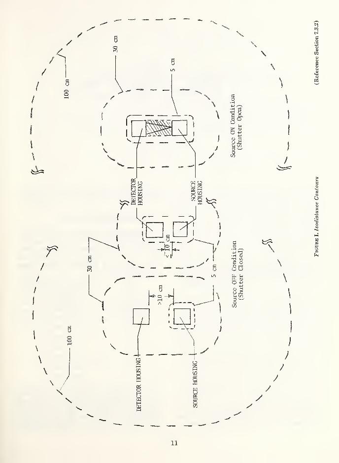
Isodistance Contour. The imaginary surface around a gauge at a specified distance from the nearest accessible surfaces. For practical reasons in this standard, the literal interpre¬ tation has been simplified as defined in sec¬ tion 7.3.2 and figures I and II.
Leakage Radiation. All radiation coming from within the source housing, except the useful beam.
Nearest Accessible Surface. The accessible surface (s) of the gauge closest to the point or region of interest.
Protective Barrier. A structure or obstacle to limit access of personnel to fields of radia¬ tion. A protective barrier is distinguished from a radiation shield in that it limits per¬ sonnel access to radiation sources, whereas a radiation shield reduces radiation intensity.
Radiation Shield. The material used inten¬ tionally to reduce the intensity of radiation entering a region.
Radioactive Source. Any quantity of radioac¬ tive material which is intended for use as a source of ionizing radiation.
Scattered Radiation. Radiation that, during passage through matter, has been deviated
in direction. (It may also have been modified
by a decrease in energy.)
Source Holder. A device used to support and
retain the source.
1
Source Housing. An enclosure containing or incorporating the source, source holder, and means for attenuation of the radiation.
Stray Radiation. The sum of leakage and scattered radiation.
Usef ul Beam. Radiation which passes through the window, aperture, cone or other collimat¬ ing device of the source housing; sometimes called “primary beam.”
Use fid Beam Controls. The device (s) that af¬ fects the quantity, quality, and direction of the useful radiation beam which is emitted from the source.
X-ray Tube Source. A gauge radiation source producing penetrating electromagnetic radi¬ ation having wavelengths shorter than those of ultraviolet light. X-rays can be produced by bombarding a metallic target with fast electrons in a high vacuum, fluorescent tech¬ niques, or other means.
3. Safety Features and Requirements
3.1 Source Integrity
3.1.1 Radioactive Source. The radioactive ma¬ terial shall be in the form of a sealed source which shall be classified in accordance with the American National Standard N542-1977, “Sealed Radioactive Sources, Classification.”
3.1.2 X-ray Tube Source. The source shall be such that no radiation is emitted except by application of an electric current through an x-ray tube. Provisions shall be made to limit both the current through the tube and the voltage across the tube, so that radiation levels do not exceed the device classification under use conditions or through circuit component failures.
In the event of fire or abnormal elevated temperatures, provisions shall be made to in¬ sure the high voltage is automatically disabled before loss of any integral shielding. This pro¬ vision exempts x-ray tube sources from accident condition classification.
3.2 Source Access. The gauge shall be designed to restrict access to the source by unauthorized personnel.
3.3 Integral Radiation Shields. Shielding which is part of the gauge shall reduce the radiation emitted by the source to the levels required by the device classification.
3.4 Useful Beam Controls. A useful beam con¬ trol system shall be provided in gauges when¬ ever the useful beam is accessible and the radi¬ ation levels exceed 100 mrem/h at 5 cm from any accessible surface or 5 mrem/h at 30 cm. The useful beam controls may include (but not be limited to) the following radiation interrupt¬ ing means;
(a) Moving Shutter
(b) Moving Source
(c) High Voltage Power Supply Control (in the case of x-ray tube sources.)
The prototype useful beam control system shall be tested through a sufficient number of cycles to verify the long-term reliability of the design.
3.4.1 Manual Useful Beam Control Systems. Manual useful beam controls shall be designed so that when the source is in the OFF condi¬ tion, the measured radiation levels in the useful beam space shall be no greater than a dose rate of 5 mrem/h at 30 cm and 100 mrem/h at 5 cm (or the device stray radiation classification levels of section 6.1, whichever is greater) as measured in accordance with the procedures of section 7.3.
In the case of a gauging device with a meas¬ uring gap not exceeding 10 cm, the radiation level requirements of this section may be met by means of the useful beam control system alone or by means of an external shield in addi¬ tion to the useful beam control system. The external shield, which shall be designed for easy and secure installation on the device, shall be supplied by the manufacturer. Means shall be provided for storing the external shield on the gauging device when it is not in use as a shield.
The source housing shall be constructed in such a manner that the source can be retained in the use positions and the full OFF position. A locking mechanism shall be provided to
2
physically secure the source in the full OFF position. This locking mechanism shall be oper¬ ated only when the source is in the OFF condi¬ tion.
3.4.2 Powered Useful Beam Control Systems. A powered (non-manual) useful beam control system shall be designed such that if power fails the source will remain in, or return to, the OFF condition. With the source in the OFF condition, the measured radiation levels, in the useful beam space, shall be no greater than a dose rate of 5 mrem/h at 30 cm and 100 mrem/h at 5 cm (or the device stray radiation classification levels of section 6.1, whichever is greater) as measured in accordance with the procedures in section 7.3.
In the case of a gauging device with a meas¬ uring gap not exceeding 10 cm, the radiation level requirements of this section may be met by means of the useful beam control system alone or by means of an external shield in addition to the useful beam control system. The external shield, which shall be designed for easy and secure installation on the device, shall be supplied by the manufacturer. Means shall be provided for storing the external shield on the gauging device when it is not in use as a shield.
3.5 ON-OFF Indicators. Conspicuously visible signals, which positively indicate when the useful beam control system is in the ON condi¬ tion, and when it is in the OFF condition, shall be located on or adjacent to the radiation source housing. The signals may be electrical, mechan¬ ical, or electromechanical and shall include legi¬ ble signs describing their meanings. Addition¬ ally, for radiation fields greater than 2 mrem/h at 50 cm from the gauge or other surfaces, ON-OFF indicators shall be located so that no one can enter the radiation field associated with the gauge without being able to see the indicators, or appropriate signs shall be posted warning individuals to check the condition of the ON-OFF indicators.
3.5.1 Indicators for Manual Useful Beam Controls. Each gauging system having a man¬
ually operated useful beam control shall have a conspicuously visible signal to indicate when the beam control is in the full ON condition and
when it is in the full OFF condition. Mechanical
indicators shall be directly coupled to the moveable beam control part.
3.5.2 Indicators for Automatic Beam Con¬ trols. Each indicating system shall consist of at least one ON indicating signal and one OFF indicating signal. If lights are used, a green signal indicates the OFF condition. The red signal indicates any other condition of the useful beam control. Administrative controls shall be established to maintain the proper operation of the ON-OFF signals (i.e., lamp bulbs which fail shall be replaced immediately).
3.5.3 Indicators for X-ray Tube Source High Voltage Control. A yellow or amber warning light with the notation “HIGH VOLTAGE ON” shall be located on the control panel and on, or adjacent to, the source housing and shall light only when power is applied to the x-ray tube high voltage circuit. Administrative con¬ trols shall be established to maintain the proper operation of the HIGH VOLTAGE ON signals. If the high voltage power supply control is the sole useful beam control, the indicator require¬ ments of section 3.5 and 3.5.2 are substituted for this section.
3.6 Interlocks. Under normal conditions of use, there shall be interlocks or barricades to pro¬ hibit a person from encountering dose rates to a major portion of the body greater than 100 mrem/h. For conditions of infrequent use, or where such interlocks or barricades are physi¬ cally impossible or impractical, appropriate in¬ structions, auxiliary shielding, or administra¬ tive controls may be substituted.
On x-ray gauges, interlocks shall be incor¬ porated (e.g., access covers, etc.) to prevent
accidental exposure to the x-rays as well as the high voltages associated with the x-ray tube.
3.7 Labels
3.7.1 Identification. The gauge shall be dura¬ bly and conspicuously marked, by a label (s)
permanently affixed to the gauge, with the ANSI gauge classification, name of the manu¬ facturer or vendor, and gauge model number.
3.7.2 Radiation Safety. Radiation safety la¬
bels shall provide instructions and precautions for safe operation of the gauge, except that
3
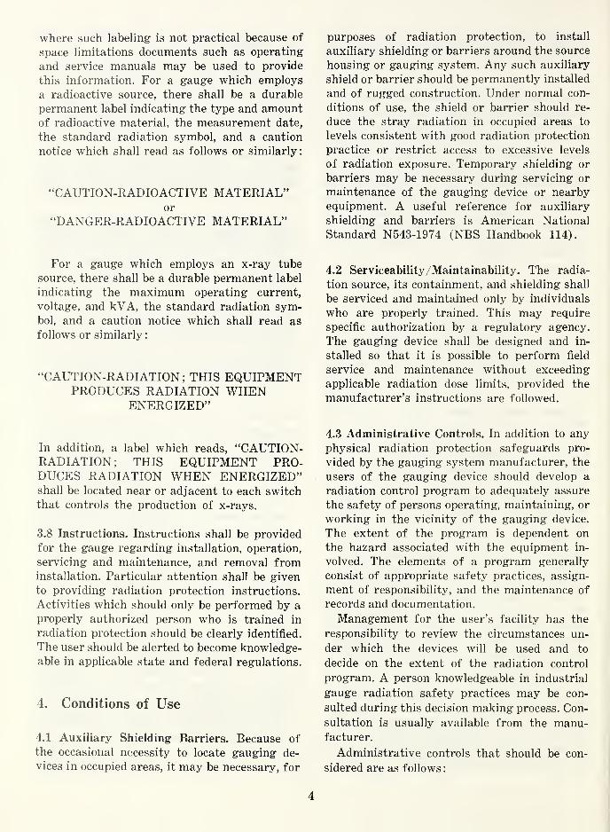
where such labeling is not practical because of space limitations documents such as operating and service manuals may be used to provide this information. For a gauge which employs a radioactive source, there shall be a durable permanent label indicating the type and amount of radioactive material, the measurement date, the standard radiation symbol, and a caution notice which shall read as follows or similarly:
“CAUTION-RADIOACTIVE MATERIAL” or
“DANGER-RADIOACTIVE MATERIAL”
For a gauge which employs an x-ray tube source, there shall be a durable permanent label indicating the maximum operating current, voltage, and kVA, the standard radiation sym¬ bol, and a caution notice which shall read as follows or similarly:
“CAUTION-RADIATION; THIS EQUIPMENT PRODUCES RADIATION WHEN
ENERGIZED”
In addition, a label which reads, “CAUTION- RADIATION; THIS EQUIPMENT PRO¬ DUCES RADIATION WHEN ENERGIZED” shall be located near or adjacent to each switch that controls the production of x-rays.
3.8 Instructions. Instructions shall be provided for the gauge regarding installation, operation, servicing and maintenance, and removal from installation. Particular attention shall be given to providing radiation protection instructions. Activities which should only be performed by a properly authorized person who is trained in radiation protection should be clearly identified. The user should be alerted to become knowledge¬ able in applicable state and federal regulations.
4. Conditions of Use
4.1 Auxiliary Shielding Barriers. Because of the occasional necessity to locate gauging de¬ vices in occupied areas, it may be necessary, for
purposes of radiation protection, to install auxiliary shielding or barriers around the source housing or gauging system. Any such auxiliary shield or barrier should be permanently installed and of rugged construction. Under normal con¬ ditions of use, the shield or barrier should re¬ duce the stray radiation in occupied areas to levels consistent with good radiation protection practice or restrict access to excessive levels of radiation exposure. Temporary shielding or barriers may be necessary during servicing or maintenance of the gauging device or nearby equipment. A useful reference for auxiliary shielding and barriers is American National Standard N543-1974 (NBS Handbook 114).
4.2 Serviceability/Maintainability. The radia¬ tion source, its containment, and shielding shall be serviced and maintained only by individuals who are properly trained. This may require specific authorization by a regulatory agency. The gauging device shall be designed and in¬ stalled so that it is possible to perform field service and maintenance without exceeding applicable radiation dose limits, provided the manufacturer’s instructions are followed.
4.3 Administrative Controls. In addition to any physical radiation protection safeguards pro¬ vided by the gauging system manufacturer, the users of the gauging device should develop a radiation control program to adequately assure the safety of persons operating, maintaining, or working in the vicinity of the gauging device. The extent of the program is dependent on the hazard associated with the equipment in¬ volved. The elements of a program generally consist of appropriate safety practices, assign¬ ment of responsibility, and the maintenance of records and documentation.
Management for the user’s facility has the responsibility to review the circumstances un¬ der which the devices will be used and to decide on the extent of the radiation control program. A person knowledgeable in industrial
gauge radiation safety practices may be con¬ sulted during this decision making process. Con¬ sultation is usually available from the manu¬ facturer.
Administrative controls that should be con¬ sidered are as follows:
4
(a) Posting of safety notices to employees and various warning signs when re¬ quired or desired.
(b) Instructions to operators and persons maintaining the gauging devices.
(c) Records retention:
(1) Documentation of receipt of the de¬
vice.
(2) Location of gauge in the user’s fa¬ cility and initial radiological survey results.
(3) Leak tests and shutter operation test results when required.
(4) Personnel monitoring results.
(5) Documentation of disposal of the de¬
vice.
(d) Availability of a radiation protection specialist either employed by the user or available on contract, whose func¬ tion would be to:
(1) Design and implement a radiation protection program to reduce and maintain personnel exposures to a level as low as is reasonably achiev¬ able.
(2) Provide for training of personnel
where applicable.
(3) Consider personnel monitoring needs.
(4) Provide internal audits to review the overall radiation protection pro¬ gram.
Administrative controls such as special in¬ structions, operating limitations, warning signs or signals, or other controls may be substituted for physical safeguards when the physical safe¬ guards are not feasible. Any administrative control established under these conditions should insure that persons working around the gauging system will be prevented from receiv¬ ing an annual cumulative whole body dose greater than 500 mrem.
4.4 Licensing and Registration. Federal and state
regulatory requirements should be reviewed prior to obtaining the gauging device. A con¬
venient source of information may be the manu¬
facturer or distributor of the device.
5. Shipping
5.1 Packaging and Transportation. The pack¬ aging and transportation of radiation gauging devices shall comply with the applicable require¬ ments of the pertinent regulatory or controlling authorities. Each shipper should establish pro¬ cedures for determining that each package sub¬ mitted to a carrier for transport has been cor¬ rectly packaged and labeled in accordance with the appropriate regulations. Consultation is usually available from regulatory or control¬ ling authorities or the gauge manufacturers. Prior to delivery of a package to a carrier for transport, the shipper shall assure that any special instructions needed to safely open the package have been sent or otherwise made available to the recipient.
5.2 Temporary Shielding. Each gauging device shall be provided with a shutter restraint or temporary shielding that will assure that the radiation field does not exceed applicable limits during shipping and storage. The shielding or shutter restraint shall be firmly fixed to with¬
stand the normal conditions of handling and shipping. Gauging devices which employ an
x-ray tube source are excluded from the re¬ quirements of this section, provided that ca¬
pacitor discharge type gauges have the ca¬
pacitor banks discharged so there can be no
emission of x-rays. Adequate discharge of the capacitors shall be verified by using a suitable
radiation monitoring instrument to show that
no radiation is present.
6. Device Safety Performance Classification
6.1 Device Classification. Table I is a listing
of test conditions and measurements to which
a device may be subjected. The tests are ar¬
ranged in order of increasing severity. The
classification of each device type shall be de¬ termined by prototype testing for each test
in the table or by calculations based on previous tests and physical characteristics data which
demonstrate that, if the test were performed,
the device would pass the test.
5

This standard applies only to safety consider¬ ations and does not imply that the gauge will operate as a measurement system during or after the tests. The order of testing is im¬ portant only in that the stray radiation class must be determined first.
Compliance with the “accident condition” tests shall be determined by the ability of the gauge to maintain reasonable radiological safety. However, the safety features do not need to be operational or perform in accordance with their original intended functions. The nec¬ essary criteria for passing each accident test are that there shall be no dispersal of radio¬ active material and the source capsule shall re¬ main captive in a protective source housing. Dummy sources may be used in these evalua¬ tions.
It should be noted that the maximum stray radiation dose rates in table I are determined at distances measured from the nearest acces¬ sible surface of the device. Since the dimen¬ sions of devices vary considerably, there is no specific relationship within a given classification between the dose rates at 5 cm, 30 cm, and 100 cm that will hold for all devices (i.e., the in¬ verse square law does not apply).
Use of the ANSI classification for a gaug¬ ing device signifies that not only have the conditions of table I been met, but also that the guidelines for the other safety features of this standard have been followed. Some of these can be complied with only after the sys¬ tem is installed in the user’s facility (such as interlocks, remote indicators, and signs). Ac¬ complishment of full satisfaction may require the combined efforts of the manufacturer, the installer, and the user.
6.1.1 Classification Designation. The classifi¬ cation of a gauging device shall be designated by the code ANSI followed by groups of digits that identify the tests which the gauge has met and a letter which designates a radio¬ active or x-ray tube source. Classification of temperature performance and accident condi¬ tions is not dependent on the source ON or source OFF condition. However, classification of the stray radiation performance is dependent on the source ON or OFF condition. This
standard recognizes this difference and assigns
a separate set of digits for the source ON and
OFF conditions for the stray radiation classifi¬
cation. This standard also recognizes the dif¬ ference between radioactive and x-ray tube
sources. Thus the fire test is not required for
x-ray tube sources, provided the conditions of
3.1.2 are met.
The gauge classification shall be described
using the following format after the code name
ANSI:
A set of two digits which identifies the performance for temperature—first digit
high temperature; second digit low tem¬
perature.
Followed by a dash and
A set of three digits which identifies the performance for stray radiation in the
source ON condition—first digit for 5 cm,
second digit for 30 cm, third digit for 100 cm.
Followed by a dash and
A sef of three digits which identifies the performance for stray radiation in the source OFF condition—first digit for 5 cm,
second digit for 30 cm, third digit for 100 cm.
Followed by a dash and
The letter R for radioactive source or the letter X for x-ray tube source.
Followed by
A digit which identifies the performance
for the fire accident condition, except that
this digit is generally omitted for an x-ray
tube source.
6

Tab
le I
. C
lass
ific
ati
on o
f D
ev
ice S
afe
ty P
erf
orm
ance S
tandard
s.
in .2
8. in
o o O CM O ?H <X> yH
O fe o o O CM O LO ^ O
Q fe o o O CM O l> CO LO
O fe o o O CM O 05 CM CO
O fe o o UO yH O CM
CM
O fe
O fe o ° o © 5 ^
O o o O CM LO CM
£2 S £ 5 o « ^ i- E-, o>
8" Cl g > a>
?§
co w fc>
.3 «
8, CO
O fe o o O 00 O TJI
O fe
U O o O O I I
O [x,
U fe
w 0)
o £
V ft
g V
H
.3 '3
& CO
o b CM 05
© s io S
T3 CO
tf >> a u
+5 CO
8, CO
lO CN
lO g
© £
g
o £ CM 05
© £ lo a>
C .2 ’-3 .2 >r3
cO H . Ǥ
8, CO
10 s (M ft ® «H
X 1C > t- 6 © £
« g « u ® rt s CO cc
a fe o o CO O 05 O o o tH CM
O fe _i o o ^ o o CM H ^
O 00
O fe o o
O CM O 05 t>
O o o O 1C O t> 00 Tf
^3 c a5
05
O fe o o 00 o CO o IO o
o z
£ o
o O Es
o o
bC c '5 s (4 be
OJ -c
s g be o ® !h
'W "ft C C rt g
<N
CO ^
c$
05 O-
a £
05 P Q
05 05 xfi O ifl c o
’-*3 *5 c p o 05
rG
05
rs > o
a
05 -Q 3
>» cj U i
X O
>%
'E a c3
+» c p zn 8
•+J C/2 05
-*->
W
S H
05 > 5-
7
neu
tro
n s
ou
rce a
nd h
en
ce C
lass
1 w
ill
be
specif
ied
.

Example: A typical beta radiation transmission gauge used to measure the thickness of a plastic film might be classified:
ANSI - 32-354-564-R2
HIGH TEMPERATUR
LOW TEMPERATURE
bJ
SOURCE “ON” RADIATION LEVEL
5 cm—
30 cm—
100 cm—
-ACCIDENT CONDITION
-RADIOACTIVE SOURCE
SOURCE “OFF” RADIATION LEVEL
-100 cm
—30 cm
—5 cm
6.2 Other Conditions
6.2.1 Other potential use and accident condi¬ tions which might need further consideration but do not lend themselves to a rigid classifica¬ tion scheme include:
(a) Corrosion
(b) Vibration
(c) Impact
(d) Puncture
(e) Compressive Loads
(f) Explosion
(g) Flooding
(h) Distance to Work Stations
(i) Personnel Occupancy Times
(j) Maintenance (Gauge and Nearby Equipment)
6.2.2 Factors which should be considered by
the gauge user and manufacturer in determin¬
ing the need for additional evaluation or test¬ ing are:
(a) Consequences of loss of activity.
(b) Quantity of radioactive material con¬ tained in the gauge.
(c) Radiotoxicity of the source material.
(d) Chemical and physical form of the radioactive material.
(e) Environment to which the gauge might be exposed.
(f) Protection afforded by the sealed source capsule (ref. ANSI N542, Sealed Radio¬ active Sources, Classification).
(g) Protection afforded the source by the gauge or source/gauge combination.
(h) Additional protection provided by auxiliary safety systems (i.e., crash barriers, shock mounts, fire protection systems, etc.)
(i) Effects of loss of shielding.
7. Testing Procedures for Table I
7.1 General. The testing procedures given in this section present acceptable procedures for determining performance classification num¬ bers. All the criteria set are the minimum re¬ quirements. Procedures which can be demon¬ strated to be at least equivalent are also acceptable.
7.2 Use Condition Temperature Tests
7.2.1 Test Equipment. The device shall be tested in a temperature chamber capable of achieving and maintaining the minimum and maximum temperatures in the classification table when the device is operating with its normal heat load. Two chambers may be used, if necessary, to provide the temperature values. The device may be transferred, at room tem¬ perature, from the low temperature chamber following the low temperature portion of the cycle. Means shall be provided for monitoring the performance of the safety features of the device during the temperature test.
7.2.2 Preparation. The time required for tem¬ perature stabilization of the entire device at the temperature extremes shall be determined. The time may be determined experimentally or by calculation. Stray radiation from the device
8

shall be measured and recorded prior to begin¬ ning of the test.
7.2.3 Procedure. The device shall be placed in the chamber at room temperature and checked for proper operation of the safety features. The ambient air temperature shall be decreased to the low value shown in the classification table and shall be maintained at that value for the stabilization time plus one hour. After achiev¬ ing stabilization the operation of the safety devices shall be verified and then again at 30 min and at the conclusion of this portion of the temperature cycle. The temperature shall be increased to room temperature and main¬ tained for the stabilization time. At the con¬ clusion of this portion of the cycle, the operation of the safety features shall again be verified.
The ambient air temperature shall be in¬ creased to the high value shown in the classifi¬ cation table and maintained at that value for the stabilization time plus one hour. After achieving stabilization the operation of the safety devices shall be verified and then again at 30 min and at the conclusion of this portion of the temperature cycle. The temperature shall be decreased to room temperature and maintained for the stabilization time. At the conclusion of this portion of the cycle operation of the safety features shall again be verified. The device shall be removed from the chamber and examined visually for defects. Stray radia¬ tion of the device shall be measured and re¬ corded and the integrity of the source shall be verified.
7.2.4 Evaluation. During the temperature
cycle there shall be no failure causing loss of function of the safety features. The visual
examination shall reveal no defect which could result in loss of function of the safety features.
Stray radiation at the conclusion of the tem¬ perature test shall not exceed the value re¬
corded prior to the test. The sealed source
capsule shall pass an appropriate leak test as described in ANSI N542. An x-ray tube source
shall continue to operate within the original system radiation safety design specifications.
7.3 Stray Radiation
7.3.1 Equipment. For purposes of these tests
when measuring beta or electromagnetic radia¬
tion (gamma, x-ray, bremsstrahlung), the standard instrument shall be an air ionization chamber survey meter. The gamma and x-ray energy response of the standard meter shall be flat within ±15 percent over an energy range of 15 keV to 1.3 MeV. Other meters may be used when they are corrected for response against the standard instrument for the radia¬ tion to be measured. The window thickness of the standard meter shall be no greater than 7 mg/cm2. Additional absorbers may be required for gamma and x-ray measurements above 660 keV to obtain the corrected instrument energy response.
For purposes of these tests, wrhen measuring neutron radiation, the standard instrument shall be a survey meter whose response in dose equivalent rate units (mrem/hour) is known over the energy range of .025 eV to 10 MeV. Window thickness requirements are not ap¬ plicable to this type of instrument. The ex¬ ternal absorbers specified in 7.3.2.1 shall not be used when measuring neutron radiation.
The survey meter used for these tests shall have been calibrated to the center of the probe’s active volume not more than six months prior to the date of these tests. Beta-gamma survey meters shall be calibrated against a gamma radiation standard to an accuracy of ±10 per¬ cent of full scale at a point within the rated energy range. Neutron survey meters shall be calibrated in dose equivalent rate units to an accuracy of ±15 percent of full scale using a neutron source whose spectrum is within the instrument’s rated energy range. (For calibra¬ tion procedures, refer to American National Standard N323.) For additional discussion of survey meters, see appendix A.
7.3.2 Procedure. For measurement of stray radiation, the standard conditions shown in table II shall be established. If various isotopes and activities may be installed in a device, eval¬ uations shall be made with each isotope and activity for which a device classification is de¬ sired. However, if classification has been es¬ tablished for the maximum activity of a par¬ ticular isotope, this classification may be used for the device when incorporating lesser ac¬ tivities of the isotope. If a device incorporates more than one isotope simultaneously, tests shall be performed with all sources installed. If both neutron and gamma radiation fields are
9

present, each field shall be evaluated individu¬ ally and summed to obtain the total dose rate.
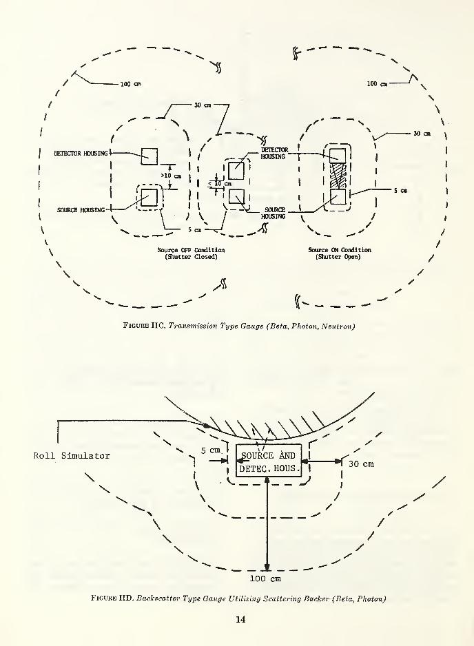
In general, the isodistance contours for measuring stray radiation are at 5 cm, 30 cm, and 100 cm from the nearest accessible surfaces of the source and detector housings of the gauge. Measuring gaps of 10 cm or less are relatively inaccessible and whole body exposure to radiation within these gaps is improbable. Therefore, the 5 cm isodistance contours are not considered in this gap space. For measur¬ ing gaps greater than 10 cm, the 5 cm isodis¬ tance contours within the measuring gap must be considered under source OFF conditions. With the source in the ON condition the meas¬ uring gap space, defined by the surface dimen¬ sions of the housings, contains the useful beam
and is excluded from consideration for defining
the isodistance contours. The locations of the
isodistance contours adjacent to the measuring gap are also simplified by making them parallel
to imaginary surfaces between the source hous¬ ing and the detector housing. These considera¬ tions are illustrated in figure I.
Figures IIA through IIF supplement table II
and illustrate the isodistance contours and
standard conditions to be used in determining
the stray radiation classification of specific types of gauges.
7.3.2.1 Beta and Electromagnetic Radia¬
tion Measurement. The location of the maximum
stray radiation shall be determined by scanning all accessible surfaces of the device with the
survey meter at the distances specified in the
classification table. After the general region of maximum radiation is located, a careful
examination shall be made to determine the
maximum radiation level. Care must be taken
in all measurements to assure that the meter is oriented to obtain a maximum reading
through the window and absorber, and that
sufficient time is allowed for the meter reading
to stabilize. Measurements shall be averaged over an area not less than 30 cm2 and not more
than 100 cm2 with no linear dimension of this
area to exceed 20 cm.
Distances shall be measured from the sur¬ face of the device to the center of the active volume of the survey meter. Dose rate meas¬
urements shall be made under two conditions
“dose rate (7 mg/cm2)” and “dose rate (300 mg/cm2)”. The first condition approximates what is commonly referred to as the dose rate to the “skin” of the body. The second con¬ dition applies to the dose rate to the “whole body, gonads, active blood-forming organs, head and trunk, or lens of the eye,” and as¬ sumes that the lenses of the eyes are not pro¬ tected by any type of eye shields. For these measurements, an external absorber shall be placed over the window of the survey meter as necessary. For measurement of dose rate (7 mg/cm2), the total thickness of window and absorber shall be no greater than 7 mg/cm2. For measurement of dose rate (300 mg/cm2), the total thickness of window and absorber shall be no greater than 300 mg/cm2. For the external absorbers, a material such as polyethylene with a low effective atomic number (specific gravity approximately 1.0) shall be used.
7.3.2.2 Neutron Radiation Measurement. The location of the maximum stray radiation shall be determined by scanning all accessible surfaces of the device with the survey meter at the distances specified in the classification table. Due to the large physical size of neutron survey meters, the measurement at 5 cm shall be eliminated. After the general region of maxi¬ mum radiation is located, a careful examination shall be made to determine the maximum radia¬ tion level. Care must be taken in all measure¬ ments to assure that the meter is oriented to obtain'a maximum reading and that sufficient time is allowed for the meter reading to stabi¬ lize. The measurement area is considered to be the cross-sectional area of the moderator. This cross-section shall include the largest dimen¬ sion of the detector. For making radiation
measurements, the cross-section which includes the largest dimension of the detector shall be placed normal to the incident radiation. Dis¬
tances shall be measured from the surface of
the device to the center of the active volume of the detector. Readings shall be interpreted as
dose equivalent rates (dose rate (300 mg/cm2)).
7.3.3 Evaluation. All documents recording
stray radiation measurements shall include
identification of the survey meter and mass per
unit area of absorbers used in making these
measurements.
10
*Sw Vs
V
X
\
\
\ C O
■H +-» S -5 § g£ u Jh g <L> O 4-»
+-> <D p U rC Si CO 3 O
CO
£ O
• H f—\ +-> T3 •H <D T3 CO £ O O i—l u u
pH Jh P-, <D O +->
4—1
0) p CJ £ CO P O
CO
\
\
\
1
i ;
/
/
y y
li
Fig
ure
I.
Iso
dis
tan
ce C
onto
urs
(Refe
rence S
ecti
on 7
.3.2
)

N
\
\
30 cm
/
Figure IIA. Density Gauge
7.3.3.1 For devices emitting beta and elec¬ tromagnetic radiation, the classification number for each distance shall be the number corre¬ sponding to the lowest radiation level in the classification table not exceeded by the maxi¬ mum dose rate (300 mg/cm2) level measured for that distance. Dose rate (7 mg/cm2) shall not exceed six times the radiation level shown in the classification table. If the dose rate (7 mg/cm2) exceeds six times the value in the classification table determined by the dose rate (300 mg/cm2) value, divide the dose rate (7 mg/cm2) by six and classify by the resultant.
7.3.3.2 For devices emitting neutron radia¬ tion the classification number at 5 cm shall be 1. The classification numbers for 30 cm and 100 cm distances shall be the numbers corre¬ sponding to the lowest radiation levels in the classification table which are not exceeded by the maximum neutron radiation levels measured at those distances. If beta and gamma radiation are present, add the beta and gamma dose radiation values to the neutron dose rates (in mrem/h at each distance. The maximum total values shall be used for classification. When the dose rate (7 mg/cm2) value resulting from beta and electromagnetic radiation, added to neutron radiation, exceeds six times the value in the classification determined by the dose rate (300 mg/cm2) value, divide the dose rate (7
mg/cm2) by six and add this value to the neu¬ tron dose rate and classify by this resultant.
7.4 Accident Condition Fire Tests
7.4.1 Equipment. The furnace used for these tests shall have a thermal capacity adequate to heat the external surfaces of the gauge being tested to the test temperature in general ac¬ cordance with the following standard time- temperature table:
TIME TEMPERATURE
0 Ambient
5 min. 538 (1000 °F)
10 min. 704 (1300 °F)
20 min. 800 (1475 °F)
30 min. 843 (1550 °F)
lh 927 (1700 °F)
2 h 1010 (1850 °F)
4 h 1093 (2000 °F)
8 h 1260 (2300 °F)
7.4.2 Procedure. All tests shall be performed in air. The temperature of the test device shall be determined by the average of readings of thermocouples disposed and distributed to show the temperature near all external parts of the
12
-I
/
/ /
/ 30 cm
-I
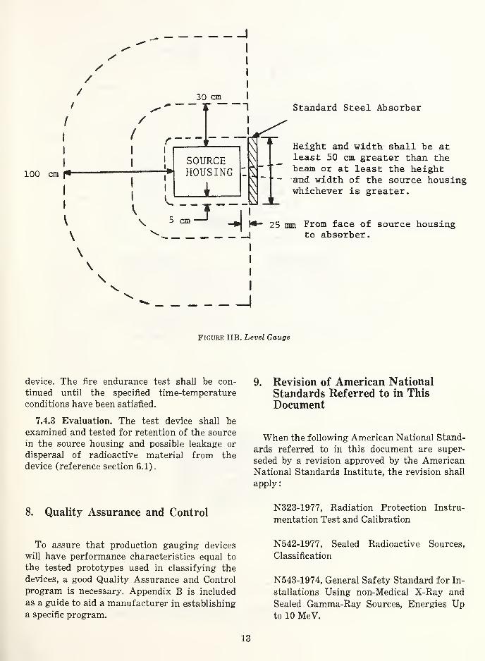
Figure IIB. Level Gauge
device. The fire endurance test shall be con¬ tinued until the specified time-temperature conditions have been satisfied.
7.4.3 Evaluation. The test device shall be examined and tested for retention of the source in the source housing and possible leakage or dispersal of radioactive material from the device (reference section 6.1).
8. Quality Assurance and Control
To assure that production gauging devices will have performance characteristics equal to the tested prototypes used in classifying the devices, a good Quality Assurance and Control program is necessary. Appendix B is included as a guide to aid a manufacturer in establishing a specific program.
9. Revision of American National Standards Referred to in This Document
When the following American National Stand¬ ards referred to in this document are super¬ seded by a revision approved by the American National Standards Institute, the revision shall apply:
N323-1977, Radiation Protection Instru¬ mentation Test and Calibration
N542-1977, Sealed Radioactive Sources, Classification
N543-1974, General Safety Standard for In¬ stallations Using non-Medical X-Ray and Sealed Gamma-Ray Sources, Energies Up to 10 MeV.
13
\ \ \
Source OFF Condition (Shutter Closed)
Source ON Condition (Shutter Open)
/
/ /
/
Figure IIC. Transmission Type Gauge (Beta, Photon, Neutron)
/
14
100
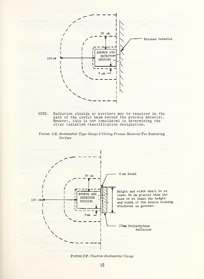
Process Material
NOTE: Radiation shields or barriers may be required in the path of the useful beam beyond the process material. However, this is not considered in determining the stray radiation classification designation.
Figure HE. Backscatter Type Gauge Utilizing Process Material For Scattering
Surface
- H
6 mm Steel
Haight and width shall be at least 50 cm greater than the beam or at least the height and width of the source housing whichever is greater.
20mm Polyethylene Reflector
Figure IIF. Neutron Backscatter Gauge
15

Table II. Standard Conditions for Stray Radiation Tests.
GENERAL
In performing the stray radiation tests for any system, the gauge (source and detector housings) shall
be mounted according to the manufacturer’s installation instruction in a physical geometry which will be
representative of the actual use condition.
SPECIFIC DEVICES
Density Gauge — Gauge mounted on process or vessel (or simula¬
tion) .
— Test for all pipe sizes (or worst case).
— Test with no process in pipe (empty).
— See Figure IIA.
Level Gauge — Source housing mounted 25 mm from a standard
13 mm thick absorber. (Vessel Wall Simulator)
— See Figure IIB.
Belt Scale Gauge — No belt or process in the measuring gap. (Empty
Air Gap)
— Test each measuring gap (or worst case).
— See Figure IIC.
Photon Transmission Gauge — No product in the measuring gap. (Empty Air
Gap)
— Test each measuring gap (or worst case).
— For x-ray gauge, test worse case combination of
operating kVp and mA available in gauge.
— See Figure IIC.
Beta Transmission Gauge — Same as Photon Transmission Gauge.
— See Figure IIC.
Neutron Transmission Gauge
A. Gauge Used on a Belt
B. Gauge used for a Product
in a Pipe or Chute
Beta Backscatter Gauge
A. Gauge used on a Roll or
Other Infinite Backer
— Same as Belt Scale Gauge.
— Same as Density Gauge.
— Test for all roll diameters (or worst case).
— Steel plate absorber (roll simulator), at the nom¬
inal measuring gap, of sufficient thickness to
attenuate all of the useful beam beta particles.
— No product on the Roll Simulator.
— See Figure IID.
B. Gauge used on Product
Not Supported or Backed up
— Typical product in the useful beam (or worst
case).
— See Figure IIE.
Photon Backscatter and Fluorescence Gauges
A. Gauge used on a Roll or Other Backer — Test for all roll diameters (or worst case).
— For x-ray gauge, test worst case combination of
operating kVp and mA available in gauge.
— Steel plate absorber (roll simulator), at the nom¬
inal measuring gap, of sufficient thickness to
attenuate 99 percent of the useful beam photons.
— No product on the Roll Simulator.
— See Figure IID.
B. Gauge used on Product
Not Supported or Backed up
— Typical product in the useful beam (or worst
case).
— See Figure IIE.
Neutron Backscatter Gauge Used on Vessels — Gauge housing mounted in contact with a stand¬
ard absorber consisting of a 6 mm thick steel
plate backed by a 20 mm thick polyethylene
reflector plate.
— No product in the measuring beam.
— See Figure IIF.
16

Appendix A
Radiation Measurement
(This appendix is not a part of American National Standard N538, Classification of Industrial Ionizing Radiation Gauging Devices.)
The following are general guidelines for measuring stray radiation of gauging devices. They are recommended to provide uniformity in making these measurements and inter¬ preting results. The specific procedure to be used in determining the stray radiation classi¬ fication is described in section 7.3.
The stray radiation from a gauging device exists in the form of a spectrum of energies. Radiation to be measured generally consists of one or more of the following: beta, gamma, x-ray, bremsstrahlung, or neutron radiation. The energy range of interest is usually be¬ tween 15 keV and 1 MeV. Scattering and secondary emission contribute to the lower energy components of stray radiation. The existence of a variety of types of radiation and energy levels requires the use of a survey meter with reasonably flat energy response. Air ionization chamber meters are available with an energy response within ±15 percent from 15 keV to 1.3 MeV. These instruments may also be suitable for measurement at energy levels outside this range by applying appropriate correction factors. Air ionization chamber meters do not measure neutron radiation.
Geiger tube survey meters may be strongly energy dependent. This type of meter should not be used for stray radiation measurements unless the meter has been corrected for response against the standard instrument for the radiation to be measured. Geiger tube survey meters are useful for preliminary scanning to locate any small voids in the shielding. Pin-hole defects are less likely to be detected by ionization survey meters. Scintillation counters are not usually suitable for quantitative stray radiation measure¬ ments.
Beta particles are emitted with a continuous energy sprectrum ranging from zero to a maximum value for the particular emitter. Dose response characteristics of any portable survey instruments for beta radiation are strongly energy dependent. As a consequence, survey instruments are generally used only to detect beta radiation but not to measure dose rate and are, therefore, not normally calibrated for beta dose rate measurements. Air ionization chamber instruments most nearly measure beta dose rates with reasonable accuracy. For this reason this type of instrument has been selected as the standard meter for this classification standard.
When pure beta emitting sources are used in gauging devices, the scattered radiation will be predominately beta while the remaining stray radiation may be bremsstrahlung. Some beta sources also emit gamma rays.
Survey meters are available with a variety of window thicknesses. For measurement of “skin” dose rates a window thickness not exceeding 7 milligrams per square centimeter is required because an individual has a protective layer of dead tissue of approximately 7 milligrams per square centimeter.
17

For measurement of “whole body (including lens of the eye, gonads, and active blood- forming organs)” dose rates a window thickness not exceeding 300 milligrams per square centimeter is required because the lens of the eye is located at a depth of 300 milligrams per square centimeter. The required thickness may be achieved by adding external absorbers over the window of the survey meter. Survey meters which will accept both absorbers are readily available.
When selecting a survey meter for measuring a particular type of radiation, the response of the meter to other types of radiation must be known so appropriate corrections can be applied. Items to be considered are: the sensitivity of the survey meter to R. F. radiation, micro-waves, neutrons in an ionizing electromagnetic radiation field, and gamma or x-ray radiation in a neutron field.
18

Appendix B
Quality Assurance and Control
(This appendix is not part of American National Standard N538, Classification of Indus¬ trial Ionizing Radiation Gauging Devices.)
Bl. Introduction All gauging devices within the scope of this standard should have associated with their
manufacture a documented quality program, possessing, as a minimum, the attributes stated in this appendix.
The authority and responsibilities of the organizational unit or individuals performing the Quality function should be stated clearly in writing.
B2. Authority Persons performing the Quality function should have the authority to:
(1) Examine all records of the gauge program which are relevant to radiation safety. (2) Reject and obtain proper disposition of defective material and workmanship.
B3. Responsibilities Persons performing the Quality function should be responsible for:
(1) Participating in design review of the gauge, identifying and suggesting neces¬ sary improvement in the gauge components which constitute or satisfy the safety features and requirements of section 3 of this standard.
(2) Monitoring the performance of, and record keeping associated with, prototype testing, and verifying that gauge production models meet the stated radiation numerical classification.
(3) Devising and implementing documented test, inspection, and corrective action procedures for gauge components which constitute or satisfy the safety features and requirements of section 3 of this standard.
(4) Establishment of an audit procedure, monitoring all aspects of the gauge pro¬ gram which may affect radiation safety such as installation, servicing, shipping and instruction manuals.
B4. References The gauge manufacturer may also find the information in the following documents
useful:
ANSI Z 1.1 GUIDE FOR QUALITY CONTROL
ANSI Z 1.8 A QUALITY PROGRAM, GENERAL REQUIREMENTS FOR
19

NBS-1 1 4A (REV. #-76)
U.S. DEPT. OF COMM.
BIBLIOGRAPHIC DATA
SHEET
1. PUBLICATION OR REPORT NO.
NBS Handbook 129
Z. Recipient's Accession No.
4. title and subtitle /\mer-jcan National Standard N538-1979; Classification of Industrial Ionizing Radiation Gauging Devices
5. Publication Date
October 1979
6. Performing Organization Code
7. author(S) /\men-can National Standards Committee N43; E. H. Eisenhower, Chairman
8. Performing Organ. Report No.
9. PERFORMING ORGANIZATION NAME AND ADDRESS
NATIONAL BUREAU OF STANDARDS
DEPARTMENT OF COMMERCE
WASHINGTON, DC 20234
11. Contract/Grant No.
12. SPONSORING ORGANIZATION NAME AND COMPLETE ADDRESS (Street, City. State. ZIP)
Same as 9. 13. Type of Report & Period Covered
Final 14. Sponsoring Agency Code
' ' ,
15. SUPPLEMENTARY NOTES
Library of Congress Catalog Card Number: 79-600113
[ | Document describes a computer program; SF-185, FIPS Software Summary, is attached.
16. ABSTRACT (A 200-word or less factual summary of most significant information. If document includes a significant bibliography or
literature survey, mention it here.)
This American National Standard applies to the radiation safety aspects of gauging devices, commonly called gauges, which use sealed radioactive sources or x-ray tubes for the determination or control of thickness, density, level, interface location, or qualitative or quantitative chemical composition. This standard establishes a system for classification of gauging devices based on performance specifications relating to radiation safety. In addition to specific tests for both use conditions and accident conditions, guidelines for other safety features and considerations are presented. This standard does not apply to the measurement performance of gauging devices.
17. KEY WORDS (six to twelve entries; alphabetical order; capitalize only the tirat letter of the first key word unices a proper name;
separated by semicolons) Qev-jce safety performance classification; gauges; gauging devices; ionizing radiation; radiation measurements; radiation safety; standard.
18. AVAILABILITY Q§ Unlimited
| | For Official Distribution. Do Not Release to NTIS
Jfyj Order From Sup. of Doc., U.S. Gojvpjqniept Printing Office, Washington, DC 20402, SD Stock No. SN003-003- 02136-1_
| | Order From National Technical Information Service (NTIS), Springfield,
VA. 22161 _
19. SECURITY CLASS (THIS REPORT)
UNCLASSIFIED
20. SECURITY CLASS (THIS PAGE)
UNCLASSIFIED
21. NO. OF PRINTED PAGES
29
22. Price
$1.75
USCOMM-DC
^.U.S. GOVERNMENT PRINTING OFFICE: 1979-311-046/296


OTHER PUBLICATIONS BY COMMITTEE N43
Order the following publications by SD Stock Number from: Superintendent of Documents U.S. Government Printing Office Washington, D.C. 20402
AMERICAN NATIONAL STANDARD N43.1; RADIOLOGICAL SAFETY IN THE DESIGN AND OPERATION OF PARTICLE ACCELERATORS. NBS Handbook 107, Revised 1978. Price: $1.30 SD Stock Number SN 003-003-02064-8
AMERICAN NATIONAL STANDARD N43.2; RADIATION SAFETY FOR X-RAY DIFFRACTION AND FLUORESCENCE ANALYSIS EQUIPMENT. NBS Handbook 111, Revised 1977. Price: $1.00 SD Stock Number SN 003-003-01917-8
AMERICAN NATIONAL STANDARD N543; GENERAL SAFETY STANDARD FOR INSTALLATIONS USING NON-MEDICAL X-RAY AND SEALED GAMMA- RAY SOURCES, ENERGIES UP TO 10 MEV NBS Handbook 114. Price: $.90 SD Stock Number SN 003-003-01377-3
AMERICAN NATIONAL STANDARD N540; CLASSIFICATION OF RADIOACTIVE SELF-LUMINOUS LIGHT SOURCES. NBS Handbook 116. Price: $1.10 SD Stock Number SN 003-003-01456-7
AMERICAN NATIONAL STANDARD N537; RADIOLOGICAL SAFETY STANDARD FOR THE DESIGN OF RADIOGRAPHIC AND FLUOROSCOPIC INDUSTRIAL X-RAY EQUIPMENT. NBS Handbook 123. Price: $.90 SD Stock Number SN 003-003-01820-1
AMERICAN NATIONAL STANDARD N542; SEALED RADIOACTIVE SOURCES, CLASSIFICATION. NBS Handbook 126. Price: $1.20 SD Stock Number SN 003-003-01903-8
AMERICAN NATIONAL STANDARD N433.1; SAFE DESIGN AND USE OF SELF-CONTAINED, DRY SOURCE STORAGE GAMMA IRRADIATORS (Category I) NBS Handbook 127. Price: $1.10 SD Stock Number SN 003-003-01913-5

U.S. DEPARTMENT OF COMMERCE National Bureau of Standards Washington, D C. 20234
OFFICIAL BUSINESS
Penalty for Private Use, $300
POSTAGE AND FEES PAID U.S. DEPARTMENT OF COMMERCE
COM-215
SPECIAL FOURTH-CLASS RATE BOOK


