Ref:080222HKN EE3110 Active Filter (Par t 1) 1 Lecture 4 Active Filter (Part I) • Introduction of passive and active filter • Categories of filter – Low pass, high pass, band-pass, band stop (no tch) • Butterworth/chebyshev/Bessel response • Poles and multiple stages • Transfer Function • Bode Plot
Transcript
Ref:080222HKN EE3110 Active Filter (Part 1) 1
Lecture 4 Active Filter (Part I)
• Introduction of passive and active filter• Categories of filter
– Low pass, high pass, band-pass, band stop (notch)
• Butterworth/chebyshev/Bessel response• Poles and multiple stages• Transfer Function• Bode Plot
Ref:080222HKN EE3110 Active Filter (Part 1) 2
Book references
• Microelectronic Circuits Analysis and Design, By Muhammad H. Rashid (PWS Publishing Company)
• Microelectronic Circuit Design, By Richard C. Jaeger and Travis N. Blalock (Mc Graw Hill)
• Introduction to Filter Theory, By David E. Johnson (Prentice Hall)
Ref:080222HKN EE3110 Active Filter (Part 1) 3
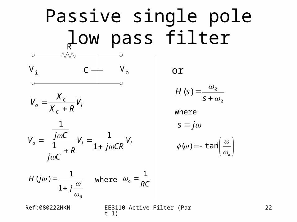
Passive Filters• made up of passive components - resistors, capacitors and in
ductors• no amplifying elements (- transistors, op-amps, etc) • no signal gain • 1st order - design is simple (just use standard equations to fi
nd resonant frequency of the circuit) • 2nd order - complex equations • require no power supplies • not restricted by the bandwidth limitations of the op-amps • can be used at very high frequencies • can handle larger current or voltage levels than active device
s • buffer amplifiers might be required
Ref:080222HKN EE3110 Active Filter (Part 1) 4
Passive elements : Inductor BIG PROBLEM!
• high accuracy (1% or 2%), small physical size, or large inductance values are required ??
• standard values of inductors are not very closely spaced
• difficult to find an off-the-shelf inductor within 10 percent of any arbitrary value
• adjustable inductors are used
• tuning such inductors to the required values is time-consuming and expensive for larger quantities of filters
• inductors are often prohibitively expensive
Ref:080222HKN EE3110 Active Filter (Part 1) 5
Active Filter• no inductors • made up of op-amps, resistors and capacitors • provides virtually any arbitrary gain • generally easier to design • high input impedance prevents excessive loading of the
driving source • low output impedance prevents the filter from being
affected by the load • at high frequencies is limited by the gain-bandwidth of the
op-amps • easy to adjust over a wide frequency range without altering
the desired response
Ref:080222HKN EE3110 Active Filter (Part 1) 6
Categories of Filters
-3dB {
f2
f
A v(dB)
-3dB {
f1
f
A v(dB)
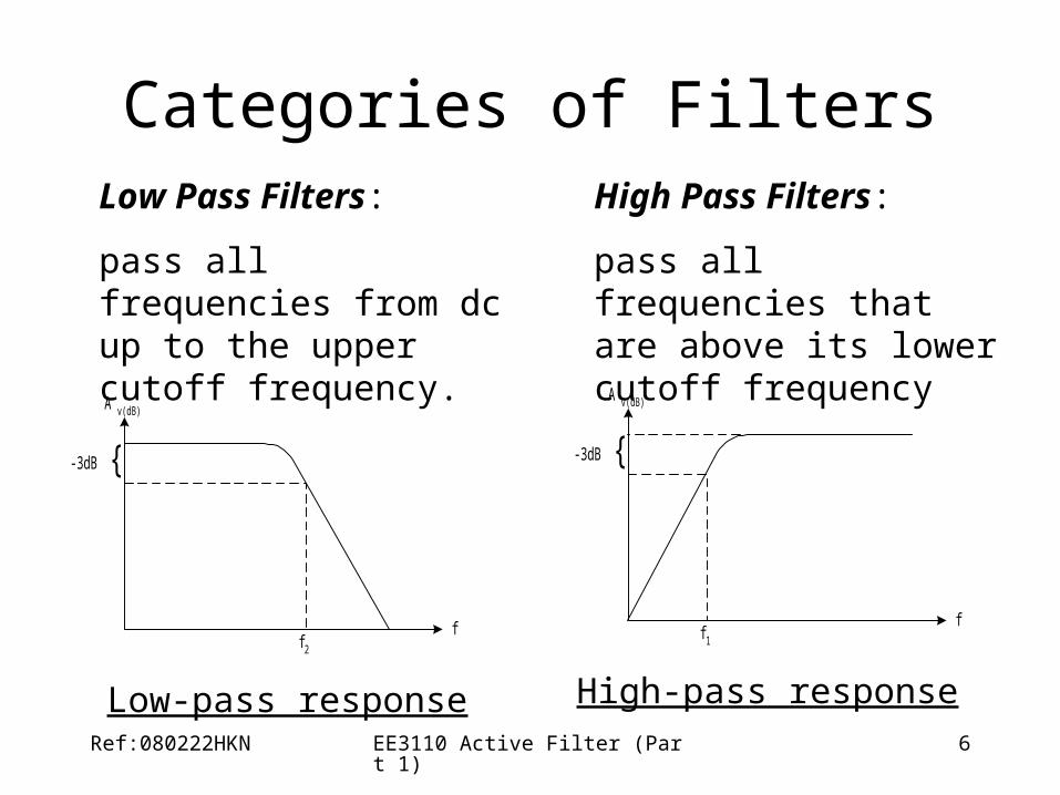
Low-pass response High-pass response
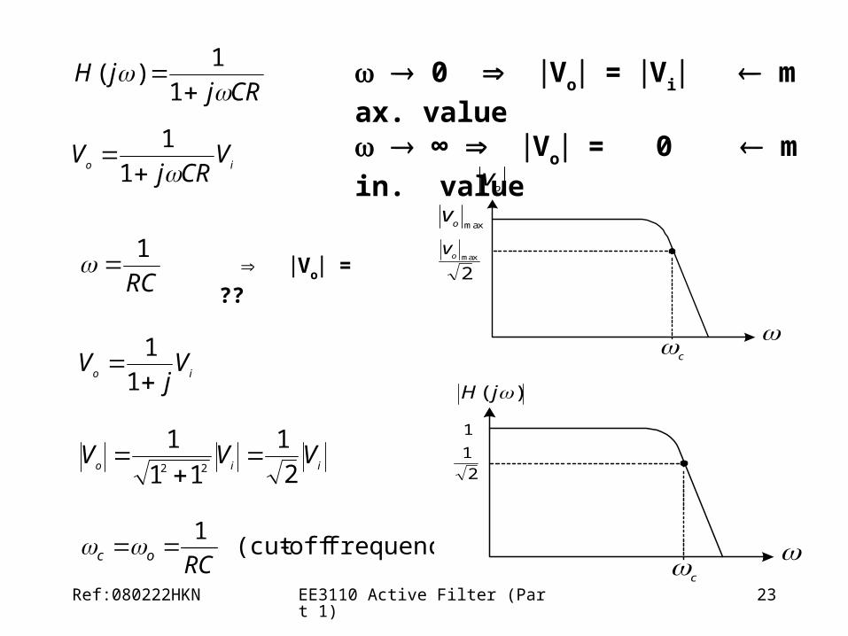
Low Pass Filters:
pass all frequencies from dc up to the upper cutoff frequency.
High Pass Filters:
pass all frequencies that are above its lower cutoff frequency
Ref:080222HKN EE3110 Active Filter (Part 1) 7
Categories of Filters
-3dB {
f2
f
A v(dB)
f1
-3dB {
ff2f1
A v(dB)
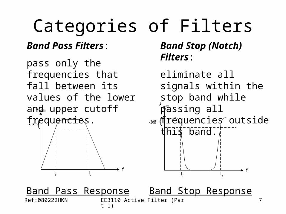
Band Pass Response Band Stop Response
Band Pass Filters:
pass only the frequencies that fall between its values of the lower and upper cutoff frequencies.
Band Stop (Notch) Filters:
eliminate all signals within the stop band while passing all frequencies outside this band.
Ref:080222HKN EE3110 Active Filter (Part 1) 8
Filter Response CharacteristicsAv
ButterworthBesselChebyshev
f
Ref:080222HKN EE3110 Active Filter (Part 1) 9
Bessel Characteristic
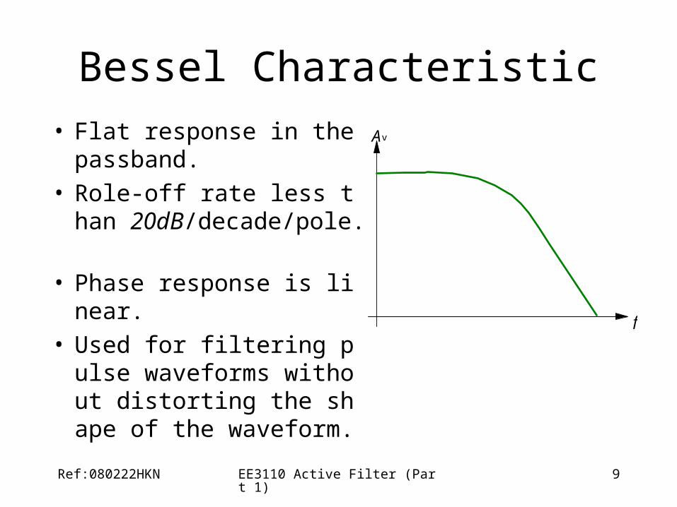
• Flat response in the passband.
• Role-off rate less than 20dB/decade/pole.
• Phase response is linear. • Used for filtering pulse w
aveforms without distorting the shape of the waveform.
Av
f
Ref:080222HKN EE3110 Active Filter (Part 1) 10
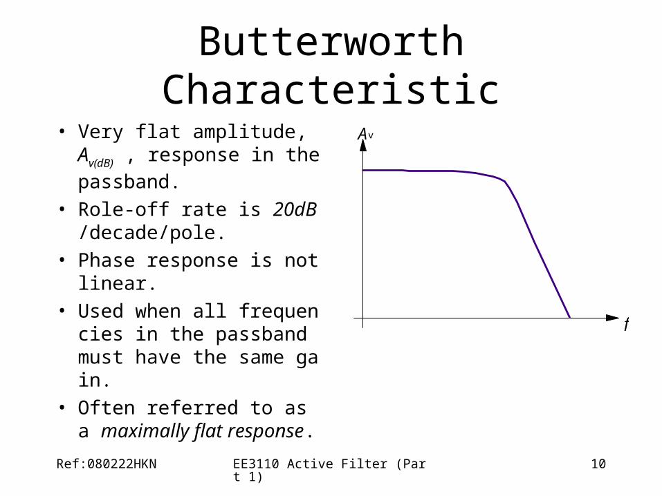
Butterworth Characteristic
• Very flat amplitude, Av(dB) ,
response in the passband.
• Role-off rate is 20dB/decade/pole.
• Phase response is not linear.
• Used when all frequencies in the passband must have the same gain.
• Often referred to as a maximally flat response.
Av
f
Ref:080222HKN EE3110 Active Filter (Part 1) 11
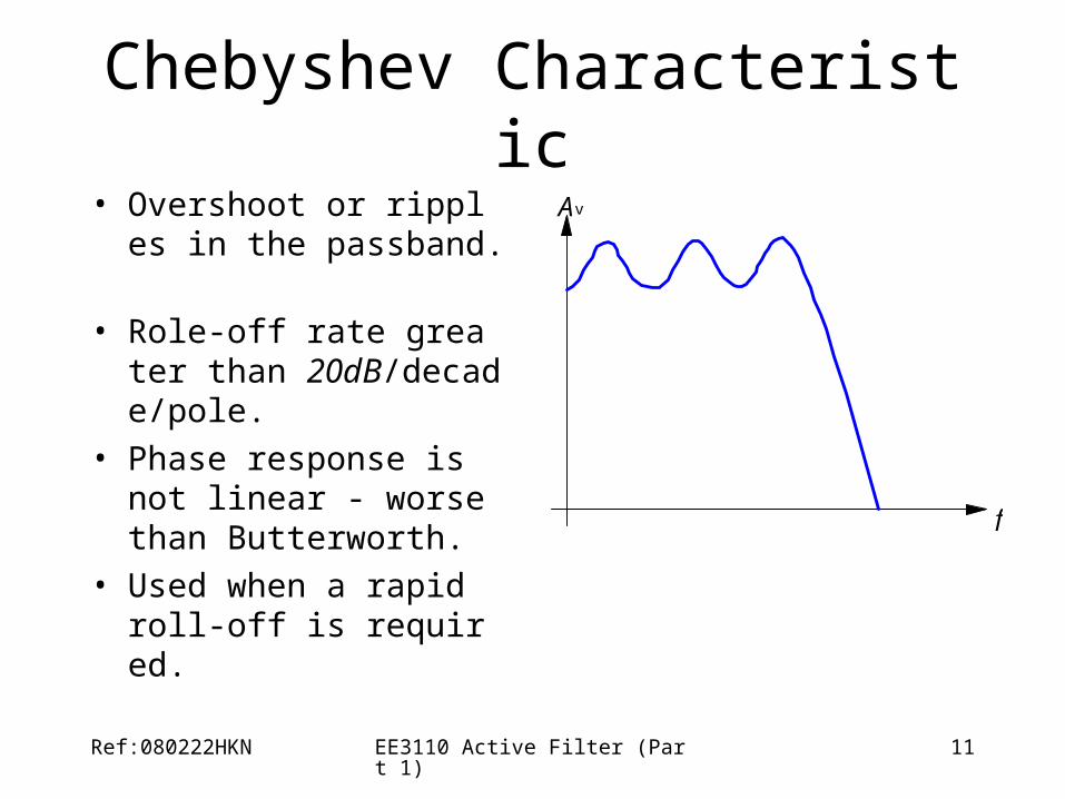
Chebyshev Characteristic• Overshoot or ripples in th
e passband.
• Role-off rate greater than 20dB/decade/pole.
• Phase response is not linear - worse than Butterworth.
• Used when a rapid roll-off is required.
Av
f
Ref:080222HKN EE3110 Active Filter (Part 1) 12
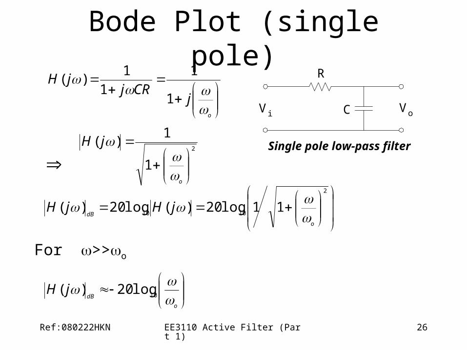
Pole
• A pole is nothing more than an RC circuit –
• n-pole filter contains n-RC circuit.
Ref:080222HKN EE3110 Active Filter (Part 1) 13
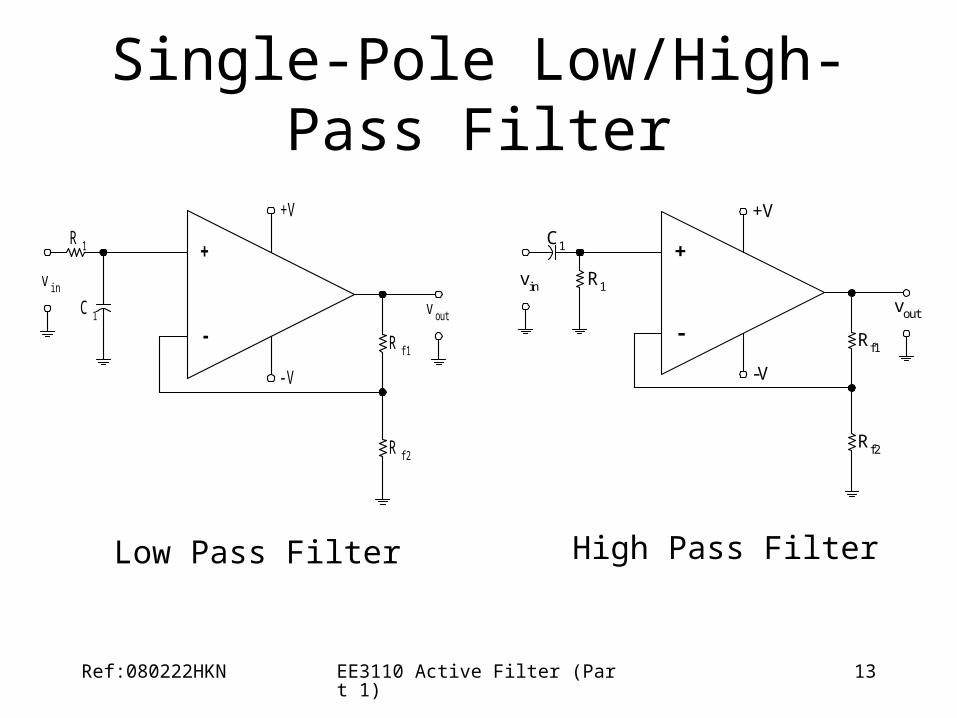
Single-Pole Low/High-Pass Filter
v out
-
+
+V
-V
R 1
R f1
R f2
C 1
v in
vout
-
+
+V
-V
R1
Rf1
Rf2
C1
vin
Low Pass Filter High Pass Filter
Ref:080222HKN EE3110 Active Filter (Part 1) 14
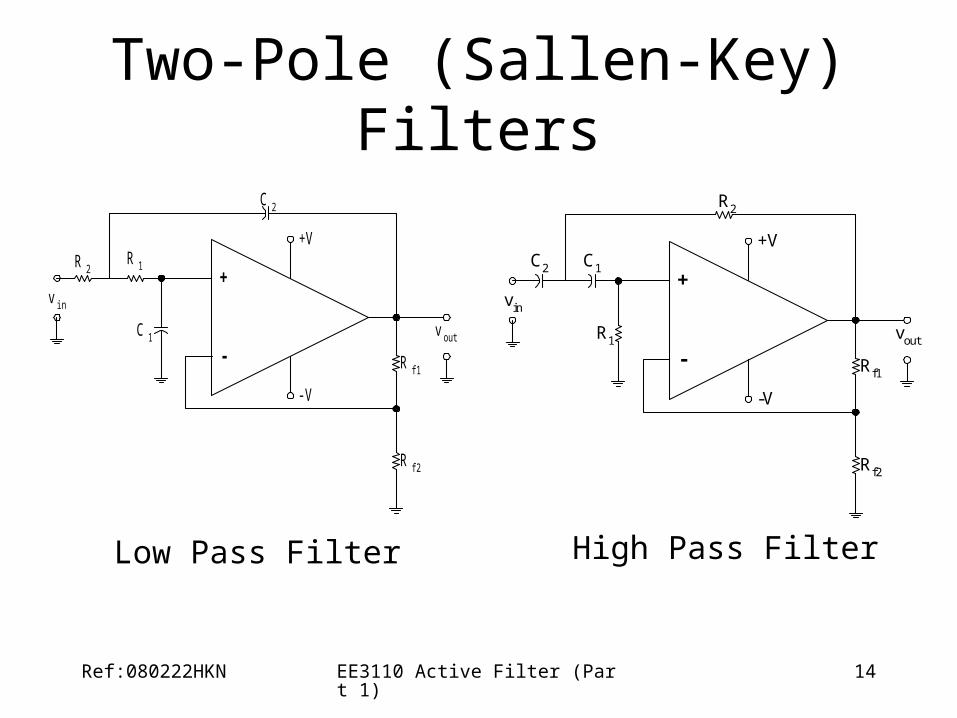
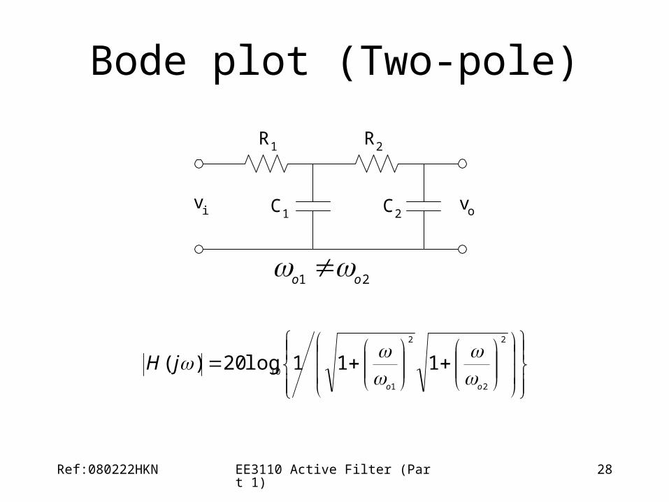
Two-Pole (Sallen-Key) Filters
-
+
+V
-V
R 1
R f1
R f2
C 1
v in
v out
C 2
R 2
-
+
+V
-V
R1
Rf1
Rf2
C2
vin
vout
R2
C1
Low Pass Filter High Pass Filter
Ref:080222HKN EE3110 Active Filter (Part 1) 15
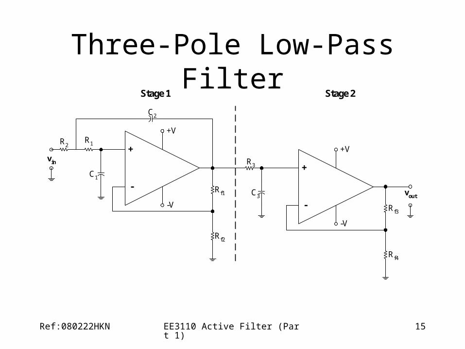
Three-Pole Low-Pass Filter
-
+
+V
-V
R1
Rf1
Rf2
C1
vin
C2
R2
-
+
+V
-V
R3
Rf3
Rf4
C3 vout
Stage 1 Stage 2
Ref:080222HKN EE3110 Active Filter (Part 1) 16
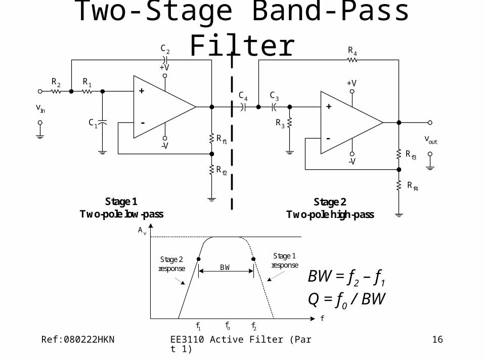
Two-Stage Band-Pass Filter
R2 R1
vin
C1
C2
Rf1
Rf2
C4 C3
R3
R4
+V
-V
vout
Rf3
Rf4
+
-
+
-
+V
-V
Stage 1Two-pole low-pass
Stage 2Two-pole high-pass
BW
f1 f2
f
Av
Stage 2response
Stage 1response
fo
BW = f2 – f1
Q = f0 / BW
Ref:080222HKN EE3110 Active Filter (Part 1) 17
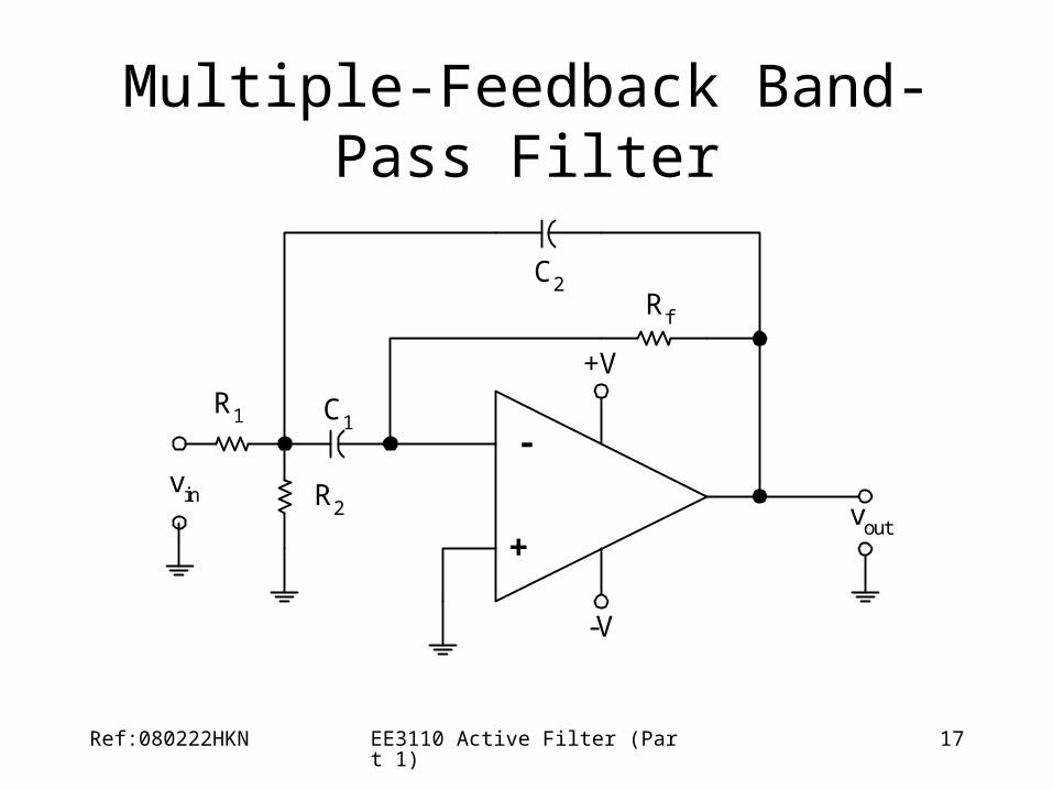
Multiple-Feedback Band-Pass Filter
R1
R2
C1
C2
vin
Rf
+V
-V
-
+vout
Ref:080222HKN EE3110 Active Filter (Part 1) 18
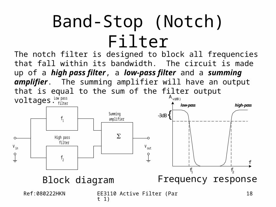
Band-Stop (Notch) FilterThe notch filter is designed to block all frequencies that fall within its bandwidth. The circuit is made up of a high pass filter, a low-pass filter and a summing amplifier. The summing amplifier will have an output that is equal to the sum of the filter output voltages.