1. Do not operate, maintain, or service machine: • Unless trained and authorized. • Unless operation manual is read and understood. • In flammable or explosive areas. • Make sure all safety devices are in place and operate properly. 2. When maintaining or servicing machine: • Disconnect battery connections before working on machine. • Avoid contact with battery acid. • Avoid moving parts. Do not wear loose jackets, shirts, ties, or sleeves when working on machine. • Use DJ Products, Inc. supplied or equivalent replacement parts. 3. Do not transport machine with covers off.
Warning:
Batteries emit hydrogen gas. Explosion or fire can result. Keep sparks and open flame away.
Attention:
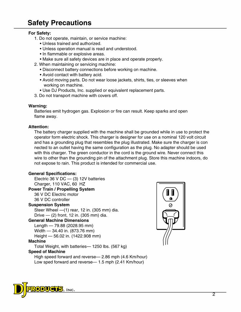
The battery charger supplied with the machine shall be grounded while in use to protect the
operator form electric shock. This charger is designer for use on a nominal 120 volt circuit and has a grounding plug that resembles the plug illustrated. Make sure the charger is con nected to an outlet having the same configuration as the plug. No adapter should be used with this charger. The green conductor in the cord is the ground wire. Never connect this
wire to other than the grounding pin of the attachment plug. Store this machine indoors, do
not expose to rain. This product is intended for commercial use.
General Specifications: Electric 36 V DC — (3) 12V batteries Charger, 110 VAC, 60 HZPower Train / Propelling System 36 V DC Electric motor 36 V DC controllerSuspension System Steer Wheel —(1) rear, 12 in. (305 mm) dia. Drive — (2) front, 12 in. (305 mm) dia.General Machine Dimensions Length — 79.88 (2028.95 mm) Width — 34.40 in. (873.76 mm) Height — 56.02 in. (1422.908 mm)Machine
Total Weight, with batteries— 1250 lbs. (567 kg)Speed of Machine
High speed forward and reverse— 2.86 mph (4.6 Km/hour) Low sped forward and reverse— 1.5 mph (2.41 Km/hour)
Safety Precautions
3
Additional Specifications
Nominal Power 3 hp continous,6 hp peakMass of most useful configuration 1250 lbs. (567 kg)Maximum draw bar pull 2000 lbs (907.2 kg)
Use of Machinery
Controls:The handle assembly can easily be adjusted if the machine comes out of neutral and
begins to creep. By removing the (4) 5/16” self-threaded screws in the yellow control box, you will gain access to the control potentiometer. Adjust the potentiometer with a 1/2 SAE wrench. Turning the potentiometer towards the front of the machine will stop the machine from creeping backwards. Turning the potentiometer towards the rear of the machine will stop the machine from creeping forward. Never adjust the potenti-ometer with the machine on. If you turn the machine on and try to adjust, the machine coule take off and cause bodyily harm.
Additional Specifications
Adjustments
4
1. Make sure the power switch is in the off (0) position.2. Using the lift handles provided on the battery, place batteries in the machine with the terminal posts shown.
For Safety:
When maintaining or servicing the machine: • Battery acid can cause burns. Avoid contact with battery acid. • When working on or around batteries, wear protective clothing, gloves, and safety glasses.
• Do not lay metal tools or metal objects on top of the batteries. • Only install deep cycle marine style lead acid batteries in your CartCaddy. The charger is built specifically for lead acid batteries. Any other battery may become overcharged and cause serious damage to the machine or operator.
• When replacing old batteries, you should replace all three batteries. This will assure the batteries will be kept in sync.3. Remove the nuts from the terminal posts. Connect the
wires as shown.
4. Make sure to attach the positive leads to the positive terminals. Place the nuts on the terminal and tighten securely.
Black
RedBlack
Black
A. Speed Button Used for high and low speed control. Push button in for low speed, pull out for high speed.
B. Spyglass Diagnostics The eight character spyglass displays a continuous sequence of hour meter, battery state of charge, and fault messages. See
the diagnostics and trouble shooting section (page 7).C. Power Key Switch The power switch controls the machine power.
Turn the key clockwise and to the horizontal position to turn the machine power on.
Turn the key counterclockwise and to the vertical position to turn off the machine power.
The machines batteries must be charged for the
machine to have power.
D. Resettable Circuit Breaker The main circuit breaker protects the motor from overload. If the load is too high, the main circuit breaker will trip and the unit will stop. To reset the circuit breaker, press the circuit breaker reset button on the accessory panel. It may be necessary to allow the circuit breaker to cool down before resetting, or it may trip again. Reduce the load before resuming. Please review the load limit sections for recommended load limits.
Installing Batteries
Accessory Panel
A B C D
5
Before operating the machine: 1. Make sure the charge is OFF by unplugging the AC power cord from the wall outlet. 2. Make sure all controls are free and clear of any obstructions. 3. Turn the power switch ON. 4. Make sure the emergency stop switch is working correctly. (Optional) 5. Make sure the safety light is operating correctly. (Optional) 6. Make sure the speed control switch is either in fast or slow speed. 7. Now you are ready to operate. If any of the safety features were not operating correctly please contact: • Your Manager • Maintenance Personnel • Your Service Representative • DJ Products, Inc.
The daily and monthly maintenance requirements listed here may be performed without tools by the machine operators. Instructions for these maintenance requirements are provided in this section of the manual.
Daily: Perform all duties listed under Pre-Operation Checklist.
Every Month: Add distilled water if needed. Water should be just over the top of the cells in the batteries.
Every Three Months: Lubricate the castor bearings with grease.
Check and tighten all fasteners and hardware. Clean, tighten, and lubricate all battery posts and cables.
Pre-Operation Checklist
Maintenance
6
The batteries have approximately an eight hour run time when fully charged. The batteries take about eight hours to charge after they have been fully discharged. The battery charger has an
automatic timer that will turn off the charger when the batteries reach full charge. The batteries
should be charged anytime the machine is not in use.
To charge the batteries: 1. Move the machine to a flat, dry surface in a well ventilated room. 2. Open the machine cover. 3. Check the water level in the battery cells. If the level is low, add just enough distilled water to cover plates. DO NOT OVERFILL. (If applicable) 4. Wipe off tops of batteries with a cloth.
5. Plug the charger into a wall outlet.
Whenever ordering parts or requesting any type of service, specify: 1. The model of the machine
2. Serial number 3. The part number
4. The part description
The CartCaddy is specifically designed to push carts and any like device resembling a cart. You should never operate the CartCaddy:
• With an operator under the age of 16. • With an operator sitting or riding on the CartCaddy or any carts it may be pushing. • With added weight not specifically added by DJ Products, Inc. or a certified service rep. • With the hood off the unit. • Without being properly trained by a supervisor. • In severe weather. • With a known feature not working correctly. • While on specific medicine that may impair your vision or reflexes.
By disregarding any of these limits, it may cause damage to the operator, your customer, and
customer’s vehicles, the CartCaddy, and your building.
Disregarding any of these limits will void your warranty in case the CartCaddy is damaged.
Charging Batteries
Service Policy
Load Limits
1 1
2 2
3 3
4 4
AA
BB
TE
EH
SY
BE
TA
DN
OIT
PIR
CS
ED
RE
V.
RE
VIS
ION
BL
OC
K
VU
PD
AT
E F
OR
1.5
0 H
AR
DW
AR
E C
HA
NG
E1/
21/1
3P
HA
LL
She
et:
PA
RT
NO
.
SC
ALE
:
DR
AF
TE
R/D
ES
IGN
ER
: RE
V. N
O:
DA
TE
:
MA
TE
RIA
L:
NA
ME
:
PR
OJE
CT
:
DJ
PR
OD
UC
TS
In
c.
1009
4T
H S
TR
EE
T N
.W.
LIT
TLE
FA
LLS
MN
563
45
UN
LES
S O
TH
ER
WIS
E S
PE
CIF
IED
:-T
OLE
RA
NC
E-
-IN
CH
ES
-.0:
.00
:
.000:
AN
GLE
S:
DR
AF
T:
FIL
EN
AM
E A
ND
PA
TH
:
FIN
ISH
PA
RT
:
SH
EE
T S
IZE
:T
IME
ST
AM
P
9/17
/200
8
7030
00X
OF
13
CA
RT
CA
DD
Y S
UP
ER
HE
AV
Y D
UT
YB.1 .0
3.0
10 3 3
PR
OD
UC
T M
AN
AG
ER
/ E
NG
INE
ER
:
C:\W
ork\
Eng
inee
ring
Des
igns
\10
Uni
t Fol
der\
7030
00 C
AR
T C
AD
DY
HD
CH
AIN
DR
IVE
\703
000
3HP
CC
SH
D A
SS
EM
BLY
\703
000.
iam
BY
AC
CE
PT
ING
TH
ISD
RA
WIN
G T
HE
RE
CIP
IEN
TA
CK
NO
WLE
DG
ES
AN
DS
TIP
ULA
TE
S T
HA
T P
RD
UC
TD
ES
IGN
S D
ISC
LOS
ED
AR
EP
RO
PR
IET
AR
Y A
ND
BE
LON
GS
SO
LELY
TO
DJ
PR
OD
UC
TS
. ALL
RIG
HT
S O
FD
ES
IGN
OR
INV
EN
TIO
N A
RE
RE
SE
RV
ED
.
02
De
c0
9 -
11
:09a
m
Par
ts L
IST
DE
SC
RIP
TIO
NR
EV
PA
RT
NO
.Q
TY
ITE
M
NO
N S
EA
LED
GR
OU
P 2
7, B
AT
TE
RY
, Dek
a 12
v 27
DC
MA
5001
55-0
73
56
SE
RIA
L D
AT
A D
ISP
LAY
A30
0166
155
TR
AN
SA
XLE
CR
AD
LE W
ELD
ME
NT
D70
3165
154
3hp
Con
trol
erA
3002
501
53
FR
ON
T C
HA
IN G
UA
RD
, TO
PB
5901
822
52
TO
P T
RA
NS
AX
LE B
RA
CE
WE
LDM
EN
TB
7030
711
51
AC
TU
AT
OR
SH
RO
UD
D70
3061
150
BA
TT
ER
Y F
RO
NT
ST
OP
D50
6011
-01
149
12"
SO
LID
TIR
EB
5001
29-0
415
48
CH
AIN
SH
RO
UD
FR
ON
T, S
IDE
PLA
TE
B59
0183
247
WA
GO
N S
TE
ER
ING
AR
M S
TO
PB
5902
801
46
ST
EE
RIN
G Y
OLK
WE
LDM
EN
T 1
.50
DIA
SH
AF
TE
7030
451
45
1.50
SH
AF
T 4
BO
LT F
LAN
GE
BE
AR
ING
B30
0225
2
44
3HP
TR
AN
SA
XLE
B50
6801
-410
143
SO
LEN
OID
5001
491
42
NE
GIT
IVE
PO
WE
R B
LKA
JB-0
001
141
HY
DR
AU
LIC
PU
MP
A30
0126
-01
140
10"
ST
RO
KE
HY
DR
AU
LIC
AC
TU
AT
OR
A30
0124
139
ST
RA
IGH
T S
TE
ER
ING
AR
M W
ELD
ME
NT
G59
0200
138
40 T
OO
TH
GE
AR
WH
EE
L H
UB
WE
LDM
EN
TH
5901
772
37
CH
AIN
SH
RO
UD
WE
LDM
EN
T, R
IGH
TD
5901
721
36
Gas
sho
ck b
all s
tud
A50
0911
-03
435
ST
AN
DE
RD
GA
S S
HO
CK
5009
11-0
1 2
34
E-
ST
OP
GA
UR
DB
5002
621
33
BU
TT
ER
FLY
CO
NT
RO
LA
5068
142
32
SW
ITC
H, M
OU
NT
ING
PA
NE
L E
ND
5004
142
31
LIF
T S
WIT
CH
-50
0405
-01
130
100
AM
P F
US
E B
LOC
KA
5003
45-0
31
29
100A
FU
SE
A50
0345
-02
128
1" H
AN
DLE
BA
R G
EA
R S
PA
CE
R50
0297
127
TO
RS
ION
SP
RIN
G
A50
0296
126
1.2
HA
ND
LE B
AR
GE
AR
SP
AC
ER
A50
0277
125
HIG
H L
OW
SW
ITC
H50
0187
-05
124
E-S
TO
P A
SS
Y-
5001
87
123
Han
dle
Bar
Grip
A50
0152
222
20 A
MP
CIR
CU
IT B
RA
KE
R-
5001
461
21
KE
Y A
SS
Y (
CH
RO
ME
) U
L R
AT
ED
5001
45-0
11
20
TO
RS
ION
SP
RIN
G C
EN
TE
RIN
G B
OLT
a50
0140
-01
119
HA
ND
LE B
AR
GE
AR
-222
079
A50
0140
1
18
PO
T G
EA
R50
0139
117
HA
ND
LE B
AR
GE
AR
BU
SH
ING
A50
0137
216
HA
ND
LE B
AR
E
5001
38-0
11
15
HA
ND
LE B
AR
WE
LDM
EN
TC
2019
2
14
CO
NT
RO
L B
OX
BO
TT
OM
J50
1288
113
CO
NT
RO
L C
OV
ER
TO
P
P50
1287
112
3 B
AN
K B
AT
TE
RY
CH
AR
GE
RA
5005
19-0
31
11
CO
MP
ON
EN
T C
OV
ER
A70
3218
110
LEF
T S
IDE
CH
AIN
SH
RO
UD
D59
0173
19
Ste
erin
g K
nuck
le W
eldm
ent
I50
1212
18
HO
OD
, CC
SH
DB
7035
431
7
2.00
" D
IA L
IFT
FO
LLO
WE
RA
3001
324
6
LIF
T P
LAT
E W
ELD
ME
NT
F70
3030
15
HU
B A
SS
EM
BLY
D50
1433
44
BE
AR
ING
, FLA
NG
ED
.75
DIA
SH
AF
T, 2
BO
LTA
3000
008
3
23 T
OO
TH
GE
AR
C30
0128
22
CA
RT
CA
DD
Y S
UP
ER
HE
AV
Y D
UT
Y F
RA
ME
U70
3003
11
WR
ED
ES
IGN
LIF
T G
UID
E S
IDE
S5/
10/1
3P
HA
LLX
UP
DA
TE
SH
RO
UD
, RE
MO
VE
TR
AN
SA
XLE
BR
AC
KE
TS
8/8/
13P
HA
LL
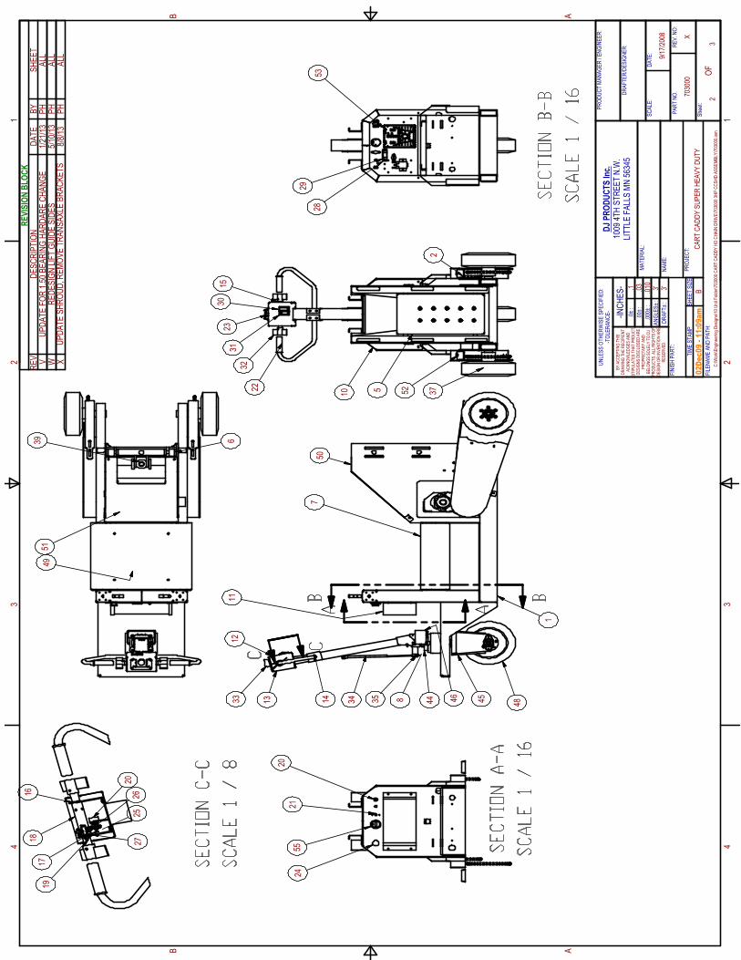
SECTION A-A
SCALE 1 / 16
SECTION B-B
SCALE 1 / 16
SECTION C-C
SCALE 1 / 8
1 1
2 2
3 3
4 4
AA
BB
TE
EH
SY
BE
TA
DN
OIT
PIR
CS
ED
RE
V.
RE
VIS
ION
BL
OC
K
VU
PD
AT
E F
OR
1.5
0 B
EA
RIN
G H
AR
DA
RE
CH
AN
GE
1/21
/13
PH
ALL
She
et:
PA
RT
NO
.
SC
ALE
:
DR
AF
TE
R/D
ES
IGN
ER
: RE
V. N
O:
DA
TE
:
MA
TE
RIA
L:
NA
ME
:
PR
OJE
CT
:
DJ
PR
OD
UC
TS
In
c.
1009
4T
H S
TR
EE
T N
.W.
LIT
TLE
FA
LLS
MN
563
45
UN
LES
S O
TH
ER
WIS
E S
PE
CIF
IED
:-T
OLE
RA
NC
E-
-IN
CH
ES
-.0 :
.00
:
.000:
AN
GLE
S:
DR
AF
T :
FIL
EN
AM
E A
ND
PA
TH
:
FIN
ISH
PA
RT
:
SH
EE
T S
IZE
:T
IME
ST
AM
P
9/17
/200
8
7030
00X
OF
23
CA
RT
CA
DD
Y S
UP
ER
HE
AV
Y D
UT
YB.1 .0
3.0
10 3 3
PR
OD
UC
T M
AN
AG
ER
/ E
NG
INE
ER
:
C:\W
ork\
Eng
inee
ring
Des
igns
\10
Uni
t Fol
der\
7030
00 C
AR
T C
AD
DY
HD
CH
AIN
DR
IVE
\703
000
3HP
CC
SH
D A
SS
EM
BLY
\703
000.
iam
BY
AC
CE
PT
ING
TH
ISD
RA
WIN
G T
HE
RE
CIP
IEN
TA
CK
NO
WLE
DG
ES
AN
DS
TIP
ULA
TE
S T
HA
T P
RD
UC
TD
ES
IGN
S D
ISC
LOS
ED
AR
EP
RO
PR
IET
AR
Y A
ND
BE
LON
GS
SO
LELY
TO
DJ
PR
OD
UC
TS
. ALL
RIG
HT
S O
FD
ES
IGN
OR
INV
EN
TIO
N A
RE
RE
SE
RV
ED
.
02
De
c0
9 -
11
:09a
m
A A
B B
C
C
33 13
12
14 34 35 8
1
7
11
10
5
32
2331
1530
22 372
39 6
55
53
16
1718
19
20
20
2124
2526
27
28
29
49
50
51W
RE
DE
SIG
N L
IFT
GU
IDE
SID
ES
5/10
/13
PH
ALL
XU
PD
AT
E S
HR
OU
D, R
EM
OV
E T
RA
NS
AX
LE B
RA
CK
ET
S8/
8/13
PH
ALL
4544
52
46
48
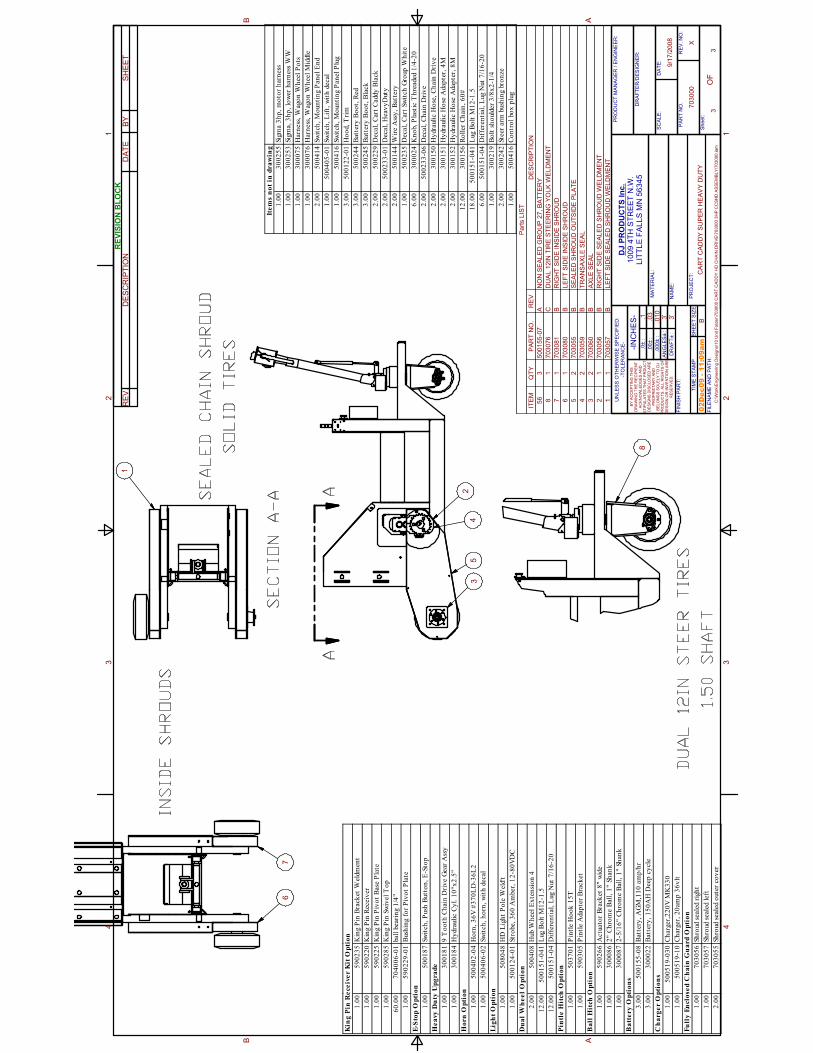
SEALED CHAIN SHROUD
SOLID TIRES
SECTION A-A
DUAL 12IN STEER TIRES
1.50 SHAFT
INSIDE SHROUDS
Kin
g P
in R
ece
ive
r K
it O
pti
on
1.0
05
90
23
5K
ing
Pin
Bra
cket
Wel
dm
ent
1.0
05
90
22
0K
ing
Pin
Rec
eiv
er
1.0
05
90
22
5K
ing
Pin
Piv
ot
Base
Pla
te
1.0
05
90
28
5K
ing
Pin
Sw
ivel
To
p
60
.00
70
40
06
-01
ball
bear
ing
1/4
"
1.0
05
90
22
9-0
1B
ush
ing f
or
Piv
ot
Pla
te
E-S
top
Op
tio
n
1.0
05
00
18
7Sw
itch
, P
ush
But
ton
, E
-Sto
p
He
avy
Du
ty U
pg
ra
de
1.0
03
00
18
19
To
oth
Ch
ain
Dri
ve G
ear
Ass
y
1.0
03
00
18
4H
ydr
auli
c C
yl.
10
"x2
.5"
Ho
rn
Op
tio
n
1.0
05
00
40
2-0
4H
orn
, 3
6V
#3
70
LD
-36
L2
1.0
05
00
40
6-0
2Sw
itch
, h
orn
, w
ith
dec
al
Lig
ht
Op
tio
n
1.0
05
08
04
8H
D L
igh
t P
ole
Wel
d't
1.0
05
00
12
4-0
1St
robe
, 3
60
Am
ber,
12
-80
VD
C
Du
al
Wh
ee
l O
pti
on
2.0
05
00
40
8H
ub W
hee
l E
xte
nsi
on
4
12
.00
50
01
51
-04
1L
ug
Bo
lt M
12
-1.5
12
.00
50
01
51
-04
Dif
fere
nti
al,
Lug
Nut
7/1
6-2
0
Pin
tle
Hit
ch
Op
tio
n
1.0
05
03
70
1P
intl
e H
oo
k 1
5T
1.0
05
90
30
5P
intl
e A
dap
ter
Bra
ck
et
Ba
ll H
itch
Op
tio
n
1.0
05
90
26
6A
ctua
tor
Bra
cket
8" w
ide
1.0
03
00
08
62
" C
hro
me B
all
, 1
" Sh
ank
1.0
03
00
08
72
-5/1
6"
Ch
rom
e B
all,
1"
Sh
ank
Ba
tte
ry
Op
tio
ns
3.0
05
00
15
5-0
8B
att
ery
, A
GM
,11
0 a
mp
/hr
3.0
03
00
02
2B
att
ery
, 1
50
AH
Dee
p c
ycl
e
Ch
arg
er O
pti
on
s
1.0
05
00
51
9-0
30
Ch
arger
,22
0V
MK
33
0
1.0
05
00
51
9-1
0C
har
ger
, 2
0am
p 3
6v
lt
Fu
lly
En
clo
se
d C
ha
in G
ua
rd
Op
tio
n
1.0
07
03
05
6Sh
roud
sea
led
righ
t
1.0
07
03
05
7Sh
roud
sea
led
left
2.0
07
03
05
5Sh
roud
sea
led
out
er c
ov
er
Ite
ms n
ot
in d
ra
win
g
1.0
03
00
25
5Sig
ma 3
hp
, m
oto
r h
arn
ess
1.0
03
00
25
3Sig
ma,
3h
p,
low
er h
arn
ess
WW
1.0
03
00
07
5H
arn
ess,
Wag
on
Wh
eel
Po
ts
1.0
03
00
07
6H
arn
ess,
Wag
on
Wh
eel
Mid
dle
2.0
05
00
41
4Sw
itch
, M
oun
tin
g P
an
el E
nd
1.0
05
00
40
5-0
1Sw
itch
, L
ift,
wit
h d
ecal
1.0
05
00
41
6Sw
itch
, M
oun
tin
g P
an
el P
lug
3.0
05
00
12
2-0
1H
oo
d, T
rim
3.0
05
00
24
4B
atte
ry B
oo
t, R
ed
3.0
05
00
24
5B
atte
ry B
oo
t, B
lack
2.0
05
00
22
9D
ecal
, C
art
Cad
dy B
lack
2.0
05
00
23
3-0
1D
ecal
, H
eav
yD
uty
2.0
05
00
14
4W
ire
Ass
y,
Bat
tery
1.0
05
00
23
5D
ecal
, C
art
Sw
itch
Gro
up W
hit
e
6.0
03
00
02
4K
no
b, P
last
ic T
hre
aded
1/4
-20
2.0
05
00
23
3-0
6D
ecal
, C
hai
n D
riv
e
2.0
03
00
15
0H
ydr
auli
c H
ose
, C
hain
Dri
ve
2.0
03
00
15
1H
ydr
auli
c H
ose
Ada
pte
r, 4
M
2.0
03
00
15
2H
ydr
auli
c H
ose
Ada
pte
r, 8
M
12
.00
30
01
56
Ro
ller
Ch
ain
, 6
0#
18
.00
50
01
51
-04
1L
ug B
olt
M1
2-1
.5
6.0
05
00
15
1-0
4D
iffe
ren
tial
, L
ug
Nut
7/1
6-2
0
1.0
03
00
21
9B
olt
sh
ould
er
3/8
x2
-1/4
2.0
03
00
24
2Ste
er a
rm b
ush
ing b
ron
ze
1.0
05
00
41
6C
on
tro
l bo
x p
lug
1 1
2 2
3 3
4 4
AA
BB
TE
EH
SY
BE
TA
DN
OIT
PIR
CS
ED
RE
V.
RE
VIS
ION
BL
OC
K
Sh
ee
t:
PA
RT
NO
.
SC
AL
E:
DR
AF
TE
R/D
ES
IGN
ER
: RE
V.
NO
:
DA
TE
:
MA
TE
RIA
L:
NA
ME
:
PR
OJE
CT
:
DJ
PR
OD
UC
TS
In
c.
10
09 4
TH
ST
RE
ET
N.W
.L
ITT
LE
FA
LL
S M
N 5
63
45
UN
LE
SS
OT
HE
RW
ISE
SP
EC
IFIE
D:
-TO
LE
RA
NC
E-
-IN
CH
ES
-.0
:
.00
:
.000
:
AN
GL
ES
:
DR
AF
T
:
FIL
EN
AM
E A
ND
PA
TH
:
FIN
ISH
PA
RT
:
SH
EE
T S
IZE
:T
IME
ST
AM
P
9/1
7/2
008
703000
X
OF
3
3
CA
RT
CA
DD
Y S
UP
ER
HE
AV
Y D
UT
YB
.1 .03
.01
03
3
PR
OD
UC
T M
AN
AG
ER
/ E
NG
INE
ER
:
C:\
Work
\En
gin
eeri
ng
Desig
ns\1
0 U
nit F
old
er\
70
30
00
CA
RT
CA
DD
Y H
D C
HA
IN D
RIV
E\7
030
00
3H
P C
CS
HD
AS
SE
MB
LY
\70
30
00
.ia
m
BY
AC
CE
PT
ING
TH
ISD
RA
WIN
G T
HE
RE
CIP
IEN
TA
CK
NO
WL
ED
GE
S A
ND
ST
IPU
LA
TE
S T
HA
T P
RD
UC
TD
ES
IGN
S D
ISC
LO
SE
D A
RE
PR
OP
RIE
TA
RY
AN
DB
EL
ON
GS
SO
LE
LY
TO
DJ
PR
OD
UC
TS
. A
LL
RIG
HT
S O
FD
ES
IGN
OR
IN
VE
NT
ION
AR
ER
ES
ER
VE
D.
02
De
c0
9 -
11
:09a
m
Pa
rts L
IST
DE
SC
RIP
TIO
NR
EV
PA
RT
NO
.Q
TY
ITE
M
NO
N S
EA
LE
D G
RO
UP
27, B
AT
TE
RY
A5001
55-0
73
56
DU
AL
12
IN T
IRE
ST
EE
RIN
G Y
OLK
WE
LD
ME
NT
C7030
76
18
RIG
HT
SID
E IN
SID
E S
HR
OU
DB
7030
81
17
LE
FT
SID
E I
NS
IDE
SH
RO
UD
B7030
80
16
SE
ALE
D S
HR
OU
D O
UT
SID
E P
LA
TE
B7030
55
25
TR
AN
SA
XL
E S
EA
LB
7030
59
24
AX
LE
SE
AL
B7030
60
23
RIG
HT
SID
E S
EA
LE
D S
HR
OU
D W
ELD
ME
NT
B7030
56
12
LE
FT
SID
E S
EA
LE
D S
HR
OU
D W
EL
DM
EN
TB
7030
57
11
AA
43
25
1
8
76
10
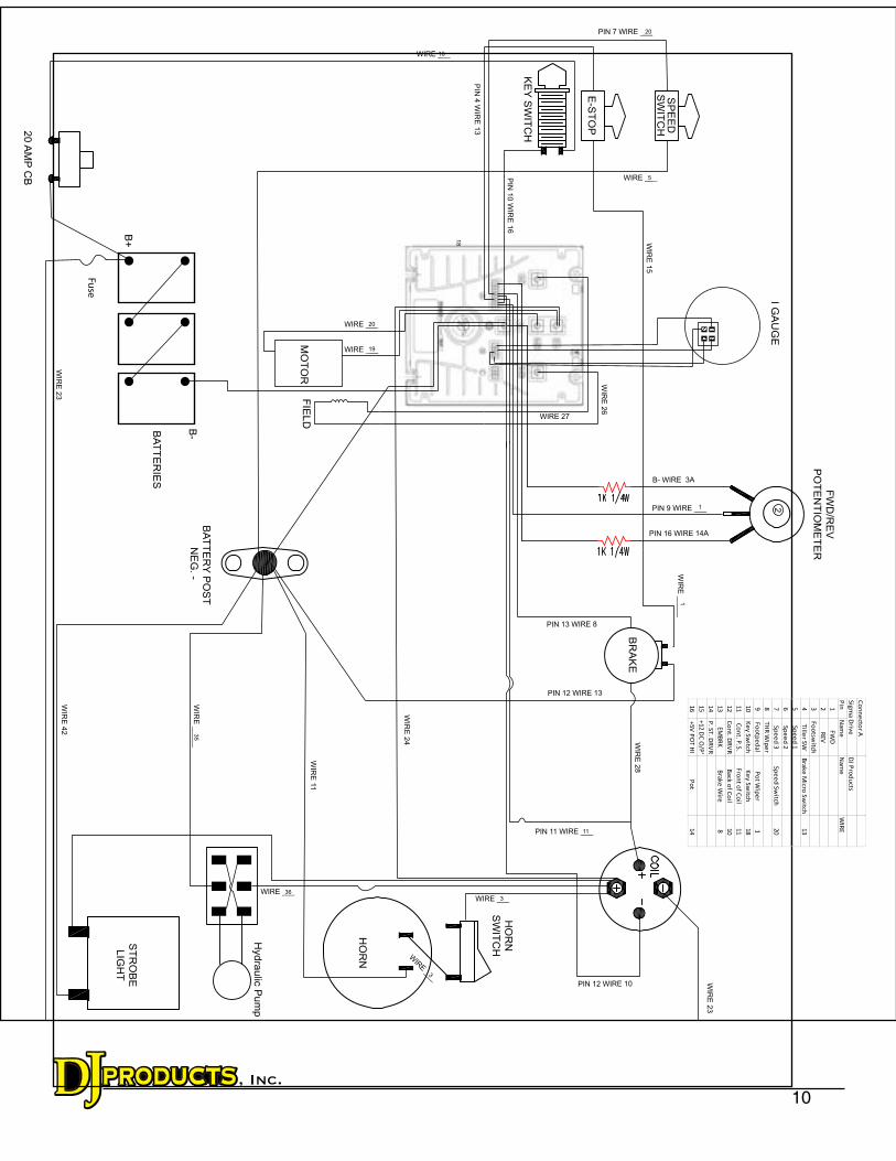
SP
EE
DS
WIT
CH
E-S
TO
P
KE
Y S
WIT
CH
BR
AK
E
HO
RN
SW
ITC
H
HO
RN
Hydra
ulic
Pum
p
BA
TT
ER
Y P
OS
T
NE
G. -
MO
TO
RF
IELD
BA
TT
ER
IES
20 A
MP
CB
FW
D/R
EV
PO
TE
NT
IOM
ET
ER
2I G
AU
GE
PIN 12 WIRE 10
WIRE ___
WIRE ___
WIRE ___WIRE ___
WIR
E ___
PIN 11 WIRE ___
PIN 12 WIRE 13
PIN 7 WIRE ___
WIRE ___
WIRE ___
PIN 9 WIRE ___
PIN 13 WIRE 8
ST
RO
BE
LIG
HT
B+
B-
WIR
E _
__
__
WIR
E 2
3W
IRE
42
WIR
E _
__
__
WIR
E 2
3
1
WIR
E 2
8
18
20
5
1
20
19
11
336
3
16
35
Fuse
WIR
E 2
4
1
11
2
34
PIN
4 W
IRE
13
PIN
10
WIR
E 1
6
B- WIRE 3A
PIN 16 WIRE 14A
WIR
E 1
1
WIR
E 1
5
WIRE 27
WIR
E 2
6
Co
nn
ecto
r A
Sig
ma
Driv
eD
J Pro
du
cts
Pin
Na
me
Na
me
WIR
E
1F
WD
2R
EV
3F
oo
tswitch
4T
iller S
WB
rak
e M
icro S
witch
13
5S
pe
ed
1
6S
pe
ed
2
7S
pe
ed
3S
pe
ed
Sw
itch2
0
8T
HR
Wip
er
9F
oo
tpe
da
lP
ot W
ipe
r1
10
Ke
y S
witch
Ke
y S
witch
18
11
Co
nt. P
.S.
Fro
nt o
f Co
il1
1
12
Co
nt. D
RV
RB
ack
of C
oil
10
13
EM
BR
KB
rak
e W
ire8
14
P. S
T. D
RV
R
15
+1
2 D
C O
/P'
16
+5
V P
OT
HI
Po
t 1
4
11
12
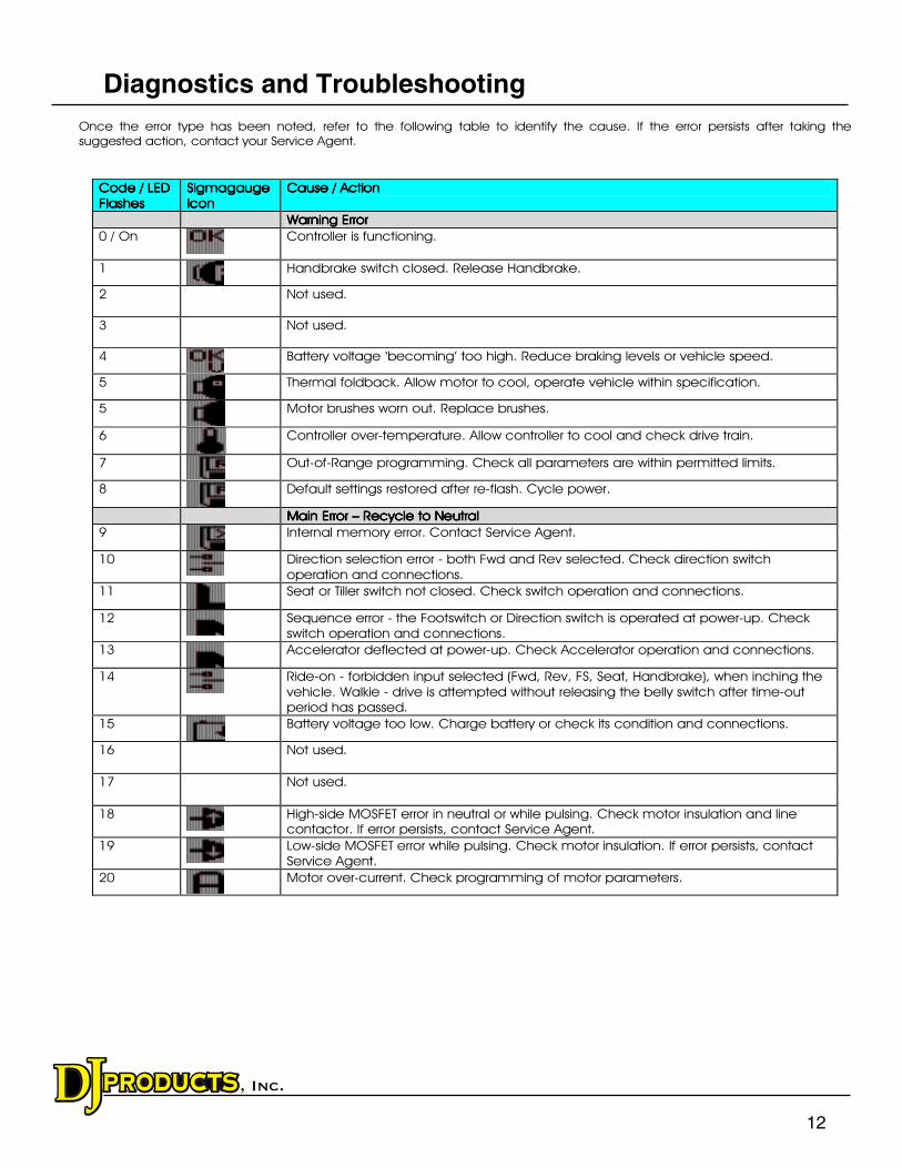
Diagnostics and Troubleshooting
13
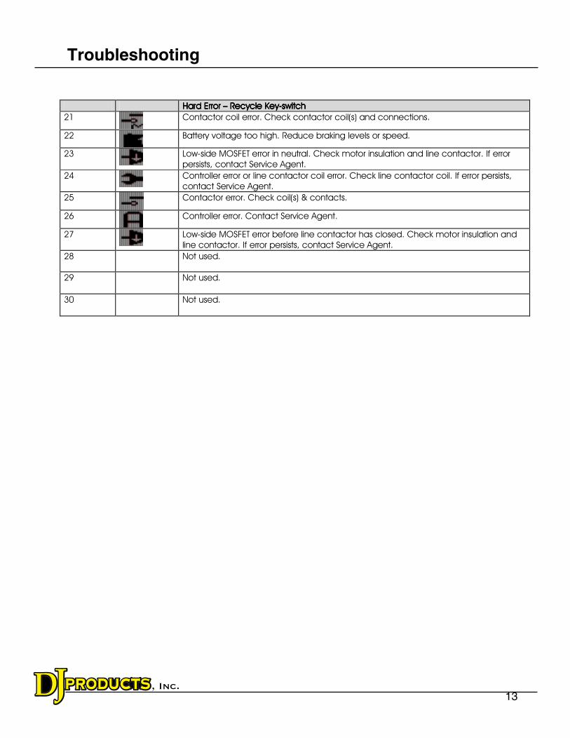
Troubleshooting
14
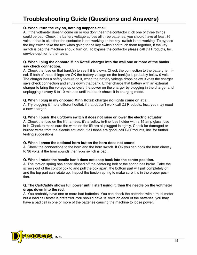
Troubleshooting Guide (Questions and Answers)
Q. When I turn the key on, nothing happens at all.A. If the voltmeter doesn’t come on or you don’t hear the contactor click one of three things could be bad. Check the battery voltage across all three batteries; you should have at least 36 volts. If that is ok either the contactor is not working or the key switch is not working. To bypass the key switch take the two wires going to the key switch and touch them together, if the key switch is bad the machine should turn on. To bypass the contactor please call DJ Products, Inc. service dept for further tests.
Q. When I plug the onboard Minn Kota® charger into the wall one or more of the banks say check connection.A. Check the fuse on that bank(s) to see if it is blown. Check the connection to the battery termi-nal. If both of these things are OK the battery voltage on the bank(s) is probably below 9 volts. The charger has a safety feature on it, when the battery voltage drops below 9 volts the charger
says check connection and shuts down that bank. Either charge that battery with an external charger to bring the voltage up or cycle the power on the charger by plugging in the charger and
unplugging it every 5 to 10 minutes until that bank shows it in charging mode.
Q. When I plug in my onboard Minn Kota® charger no lights come on at all.A. Try plugging it into a different outlet, if that doesn’t work call DJ Products, Inc., you may need a new charger.
Q. When I push the up/down switch it does not raise or lower the electric actuator.A. Check the fuse on the lift harness; it’s a yellow in-line fuse holder with a 15 amp glass fuse in it. Check to make sure the wires on the lift are all plugged in tightly. Check for damaged or burned wires from the electric actuator. If all those are good, call DJ Products, Inc. for further testing suggestions.
Q. When I press the optional horn button the horn does not sound.
A. Check the connections to the horn and the horn switch. If OK you can hook the horn directly to 36 volts, if the horn sounds then your switch is bad.
Q. When I rotate the handle bar it does not snap back into the center position. A. The torsion spring has either slipped off the centering bolt or the spring has broke. Take the screws out of the control box to and pull the box apart, the bottom part will pull completely off and the top part can rotate up. Inspect the torsion spring to make sure it is in the proper posi-tion.
Q. The CartCaddy shows full power until I start using it, then the needle on the voltmeter drops down into the red.A. You probably have one or more bad batteries. You can check the batteries with a multi-meter but a load cell tester is preferred. You should have 12 volts on each of the batteries; you may have a bad cell in one or more of the batteries causing the machine to loose power.
15
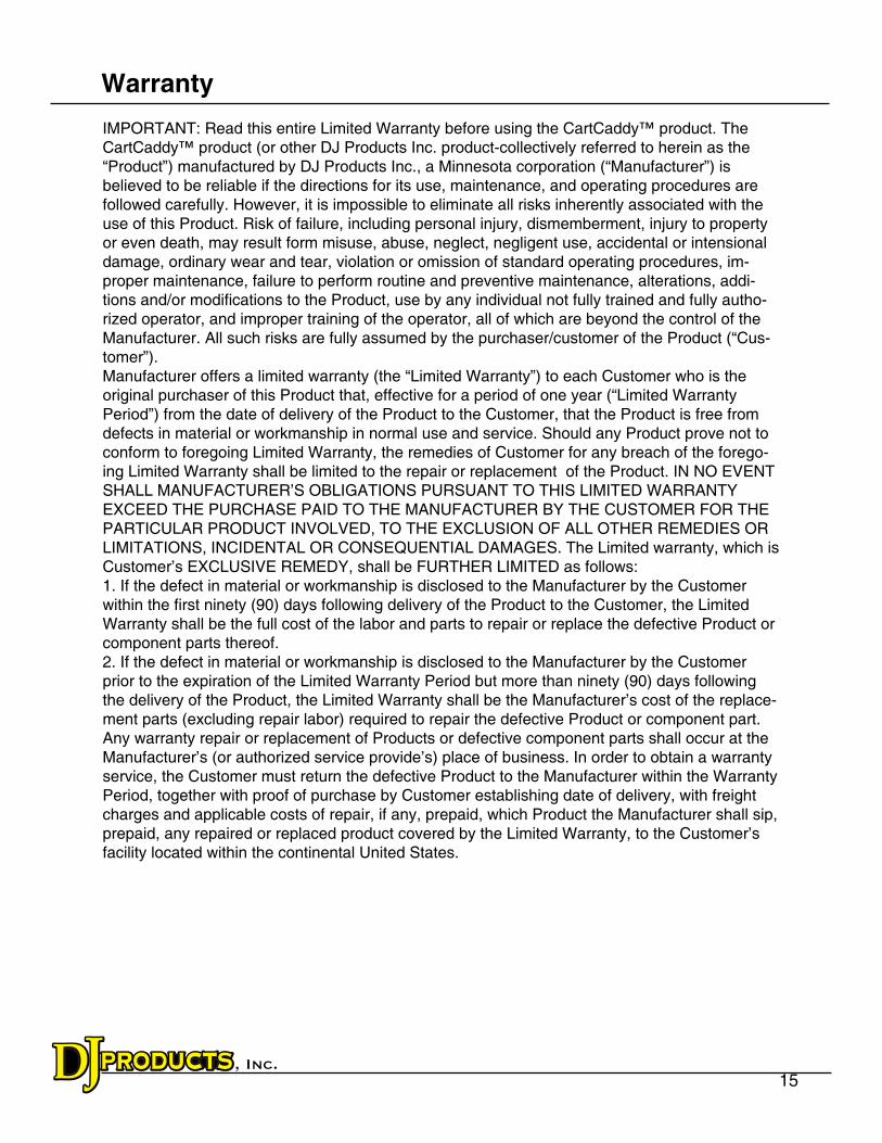
Warranty
IMPORTANT: Read this entire Limited Warranty before using the CartCaddy™ product. The CartCaddy™ product (or other DJ Products Inc. product-collectively referred to herein as the “Product”) manufactured by DJ Products Inc., a Minnesota corporation (“Manufacturer”) is believed to be reliable if the directions for its use, maintenance, and operating procedures are
followed carefully. However, it is impossible to eliminate all risks inherently associated with the use of this Product. Risk of failure, including personal injury, dismemberment, injury to property or even death, may result form misuse, abuse, neglect, negligent use, accidental or intensional
damage, ordinary wear and tear, violation or omission of standard operating procedures, im-proper maintenance, failure to perform routine and preventive maintenance, alterations, addi-tions and/or modifications to the Product, use by any individual not fully trained and fully autho-rized operator, and improper training of the operator, all of which are beyond the control of the Manufacturer. All such risks are fully assumed by the purchaser/customer of the Product (“Cus-tomer”).Manufacturer offers a limited warranty (the “Limited Warranty”) to each Customer who is the original purchaser of this Product that, effective for a period of one year (“Limited Warranty Period”) from the date of delivery of the Product to the Customer, that the Product is free from defects in material or workmanship in normal use and service. Should any Product prove not to conform to foregoing Limited Warranty, the remedies of Customer for any breach of the forego-ing Limited Warranty shall be limited to the repair or replacement of the Product. IN NO EVENT SHALL MANUFACTURER’S OBLIGATIONS PURSUANT TO THIS LIMITED WARRANTY EXCEED THE PURCHASE PAID TO THE MANUFACTURER BY THE CUSTOMER FOR THE PARTICULAR PRODUCT INVOLVED, TO THE EXCLUSION OF ALL OTHER REMEDIES OR LIMITATIONS, INCIDENTAL OR CONSEQUENTIAL DAMAGES. The Limited warranty, which is Customer’s EXCLUSIVE REMEDY, shall be FURTHER LIMITED as follows:1. If the defect in material or workmanship is disclosed to the Manufacturer by the Customer within the first ninety (90) days following delivery of the Product to the Customer, the Limited Warranty shall be the full cost of the labor and parts to repair or replace the defective Product or component parts thereof.
2. If the defect in material or workmanship is disclosed to the Manufacturer by the Customer prior to the expiration of the Limited Warranty Period but more than ninety (90) days following the delivery of the Product, the Limited Warranty shall be the Manufacturer’s cost of the replace-ment parts (excluding repair labor) required to repair the defective Product or component part. Any warranty repair or replacement of Products or defective component parts shall occur at the Manufacturer’s (or authorized service provide’s) place of business. In order to obtain a warranty service, the Customer must return the defective Product to the Manufacturer within the Warranty Period, together with proof of purchase by Customer establishing date of delivery, with freight charges and applicable costs of repair, if any, prepaid, which Product the Manufacturer shall sip, prepaid, any repaired or replaced product covered by the Limited Warranty, to the Customer’s
facility located within the continental United States.
16
The Limited Warranty is invalid if the factory-applied serial number has been altered or removed from the Product.
The Limited Warranty does not cover cosmetic damage or damage due to acts of God, accident, misuse, abuse,
neglect, negligent use, accidental or intentional damage, ordinary wear and tear, violation or omission of
standard operating procedures, improper maintenance, failure to perform routine and preventative maintenance,
alterations, additions and/or modifications to the Product, use by any individual not a fully trained and fully
authorized operator, and improper training of the operator, or repair or attempted repair by anyone other than
Manufacturer or its authorized agents, nor to any Product which is leased or used as rental equipment. The
occurrence of any of the foregoing voids the Limited Warranty.
This Limited Warranty does not cover Customer instruction or training.
THIS LIMITED WARRANTY PROGRAM IS EXCLUSIVE AND IS GIVEN AND ACCEPTED IN LIEU OF ANY AND ALL
OTHER WARRANTIES, WHETHER WRITTEN OR ORAL, EXPRESSED OR IMPLIED OR INFERABLE FROM THE
COURSE OF DEALING OR USAGE OF TRADE, INCLUDING, WITHOUT LIMITATION, THE IMPLIED WARRANTY
OF MERCHANTABILITY AND THE IMPLIED WARRANTY OF FITNESS FOR A PARTICULAR PURPOSE AND ANY
IMPLIED WARRANTY ARISING FROM PERFORMANCE, COURSE OF DEALING OR USAGE OF TRADE, AND ALL
OTHER OBLIGATIONS, LIABILITIES, RIGHTS, CLAIMS OR REMEDIES, INCLUDING ANY RIGHT IN CONTRACT,
TORT, STRICT LIABILITY OR ANY RIGHT ARISING FROM MANUFACTURER'S NEGLIGENCE, ACTUAL OR
IMPUTED.FOR CLARIFICATION ONLY (AND NOT IN ANY WAY TO EXPAND THE FOREGOING EXCLUISVE
REMEDIES):
(A) UNDER NO CIRCUMSTANCES WILL MANUFACTURER BE LIABLE FOR LOST PROFITS OR ANY OTHER
INCIDENTAL, CONSEQUENTIAL, SPECIAL OR INDIRECT DAMAGES RESULTING FROM THE PURCHASE OR
USE OF THIS PRODUCT, INCLUDING, WITHOUT LIMITATION, ECONOMIC LOSS, COST OF CAPITAL, CLAIMS
OF CUSTOMERS FOR FAILURE OF SUPPLY OR LOSS OF USE OR DAMAGE TO PERSONS OR TO OTHER
PROPERTY, NOTWITHSTANDING THE FACT THAT THE MANUFACTURER HAS BEEN ADVISED OF THE
POSSIBILITY OF SUCH DAMAGES; (B) THE TOTAL LIABILTIY OF THE MANUFACTURER TO CUSTOMER SHALL
NOT EXCEED THE TOTAL PURCHASE PRICE PAID BY THE DISTRIBUTOR TO MANUFACTURER FOR THE
PARTICULAR PRODUCT INVOLVED; AND (C) NO AGREEMENT VARYING OR EXTENDING THE FOREGOING
WARRANTIES, REMEDIES OR LIMITATIONS WILL BE BINDING UPON THE MANUFACTURER UNLESS IN
WRITING AND SIGNED BY A DULY AUTHORIZED CORPORATE OFFICER OF THE MANUFACTURER.
If any term or condition of this Limited Warranty program is in violation of applicable local, state, or federal law, this
Limited Warranty program shall not be voided in its entirety, but rather, the court, or other appropriate authority
having jurisdiction in the matter, shall rewrite and reform the Limited Warranty to the minimum extent required