This technical paper was written and developed in February 1998 when the author(s) was an employee of Dyneon LLC. Dyneon LLC was formerly a wholly-owned subsidiary of 3M Company and was fully integrated into 3M Company on January 1, 2011. Title: Die Build-up During Polyolefin Processing: A Matter of Polymer Design and Fluoropolymer-Based Processing Additives Abstract: For many years, the accumulation of material deposits on the surface of the die, commonly referred to as die build-up, has been a major obstacle for efficient processing of polyolefins. Indeed, extrusion lines ultimately have to be shut down as a thermally-degraded waxy deposit starts to affect the extrudate quality. In order to gain systematic insights into this multidisciplinary problem, a new technique has been developed. It confirmed that die build-up is related to die-swell, which provides a medium for transporting pigments, degraded polyolefin, and other materials towards the die surface. Several solutions will be proposed based on the use of fluoropolymer-based processing additives (commonly referred to as PPA) and/or the use of LLDPE’s produced with Exxpol® technology. This work is the result of a fruitful cooperation between Dyneon N.V. and Exxon Chemical. This paper was pre p a red for presentation at the PolyEthylene ‘97 World Congress organized by Maack Business Services in Milano, Italy. Date Published: February 1998
Transcript
This technical paper was written and developed in February 1998 when the author(s) was an employee of Dyneon LLC. Dyneon LLC was formerly a wholly-owned subsidiary of 3M Company and was fully integrated into 3M Company on January 1, 2011. Title: Die Build-up During Polyolefin Processing: A Matter of Polymer Design and Fluoropolymer-Based Processing Additives Abstract: For many years, the accumulation of material deposits on the surface of the die, commonly referred to as die build-up, has been a major obstacle for efficient processing of polyolefins. Indeed, extrusion lines ultimately have to be shut down as a thermally-degraded waxy deposit starts to affect the extrudate quality. In order to gain systematic insights into this multidisciplinary problem, a new technique has been developed. It confirmed that die build-up is related to die-swell, which provides a medium for transporting pigments, degraded polyolefin, and other materials towards the die surface. Several solutions will be proposed based on the use of fluoropolymer-based processing additives (commonly referred to as PPA) and/or the use of LLDPE’s produced with Exxpol® technology. This work is the result of a fruitful cooperation between Dyneon N.V. and Exxon Chemical. This paper was pre p a red for presentation at the PolyEthylene ‘97 World Congress organized by Maack Business Services in Milano, Italy.
Date Published: February 1998
D y n a m a r™
Polymer Processing Additives
Die Build-up During PolyolefinProcessing: A Matter of PolymerDesign and Fluoropolymer-BasedProcessing Additives
Linda Van den Bossche, Olivier Georjon, Theo DondersExxon Chemical Europe Inc.
Machelen Chemical Technology CenterB-1831 Machelen, Belgium
Die Build-up During Polyolefin Processing: A Matter of Polymer Design and Fluoropolymer-BasedProcessing Additives
Abstract
For many years, the accumulation of material deposits onthe surface of the die, commonly referred to as die build-up,has been a major obstacle for efficient processing ofpolyolefins. Indeed, extrusion lines ultimately have to beshut down as a thermally-degraded waxy deposit starts toaffect the extrudate quality. In order to gain systematicinsights into this multidisciplinary problem, a new techniquehas been developed. It confirmed that die build-up is relatedto die-swell, which provides a medium for transportingpigments, degraded polyolefin, and other materials towardsthe die surface. Several solutions will be proposed based onthe use of fluoro p o l y m e r-based processing additives(commonly referred to as PPA) and/or the use of LLDPE’sproduced with Exxpol® technology. This work is the result ofa fruitful cooperation between Dyneon N.V. and ExxonChemical.
This paper was pre p a red for presentation at thePolyEthylene ‘97 World Congress organized by MaackBusiness Services in Milano, Italy.
1. IntroductionDie Build-Up (DBU) is the progressive deposition of compo-nents of the extrudate exiting a die during extrusion opera-
tions. It occurs with many polymers, on virtually all convert-ing techniques such as blown film extrusion, coating, pipeand profile extrusion. Excess DBU will be brought in contactwith the external die surface, adhere to it, slowly accumulatearound the die exit where thermal oxidation takes place. Aftera while, a portion of the DBU attaches itself to the extrudate,breaks off, is carried downstream on the product, and thephenomenon starts over again. DBU gives rise to surfaceirregularities affecting aesthetic, optical and mechanical prop-erties of the extrudates. These effects worsen with time tothe extent that extrusion has to be stopped for die cleaning,at the expense of production cost-efficiency.
Although it is a significant problem, very little is known in theliterature and in the industry practice about the fundamentalmechanism of die build-up. While there is a generalconsensus on the definition of DBU, there are still manyattempts to develop a theory capable to predict accuratelyand reliably when and how much DBU will occur [1-7]. Filmproducers, resin suppliers, and machine manufacturers havetheir own theories based on limited observations. A recentpaper by Gander and Giacomin [3] gave a comprehensivereview on the subject.
DBU is undoubtedly a multidisciplinary problem, bestillustrated in an Ishikawa-type diagram shown in Figure 1.
Figure 1Die build-up is a multidisciplinaryproblem
1
98-0504-1105-1.qxd 1/16/01 2:20 PM Page 3
It illustrates the three basic factors that influence DBU : (1)chemical factors related to resin composition, (2) physicalfactors related to the processing equipment, and (3)inherent environmental factors like oxygen or moisture.Many parameters in this diagram are interrelated, withpossible synergistic or antagonistic effects. There f o re ,a p p a rently contradictory conclusions are sometimesre p o rted (thermal stability issues suggest that highertemperatures lead to faster DBU, but the problem is oftenworse for blown film than for cast despite the higherextrusion temperatures in cast. Adding metal stearates hasboth positive and negative reported effects, etc.). In fact,DBU has been tackled by different people with differentinterests and concerns. This explains the lack of a universalsolution and the use of a trial and error approach forpractical, immediate problem solving. Out of theseobservations, two directions can be delineated.
1.1 Composition analysis
Composition analysis demonstrated that DBU consists oforganic and inorganic low-molecular weight materials thathad migrated to the die surface.
These species are incompatible with the polymer, andencompass :
• low molecular weight waxy materials present in theinitial resin or resulting from thermal degradation in theextruder. This highlights the need for
- good control of the extrusion process (residence times, shear rates, etc.), and - a proper stabilization package.
• organic or inorganic additives. The latter can also triggerdegradation reactions.
Differences in surface energy will be the driving force forthis migration, and die-wall nature and cleanliness willtherefore also play a role. Reduction in adhesion at the metal- polymer interface might decrease the production rate ofDBU.
1.2 This migration is influenced bydie-swell
A material that swells a lot will have a greater propensity toaccumulate at the die exit and drag already accumulatedmaterial onto the moving web. High die-swell generallyresults from more intense processing conditions, enhancingtherefore flow-induced migration of waxy components atthe die wall. In this respect, die swell might be a major
vehicle for DBU, even if it is not the root cause of the
phenomenon.
As a matter of fact, all die geometry changes resulting in die-swell reduction (increasing die land length, increasing diegap, flaring the die exit, etc.) are already patented methodsfor DBU reduction. Not all these parameters can bemanipulated to the same degree. Die opening for exampleis fixed by the dimensional requirements of the extrudateand the polymer type (small die gap to extrude LDPE, largerfor LLDPE).
However, the magnitude of die-swell can also be controlledby a proper viscosity/elasticity balance of the polymer melt.This suggests that molecular structure (molecular weightdistribution, presence/absence of long-chain branches) canalso be tailored in order to reduce DBU, which is of coursemuch more pertinent from the point of view of a polymerp ro d u c e r. In addition, the use of fluoro p o l y m e r- b a s e dprocessing additives is also expected to result in a lower die-swell and a reduced surface energy of the metal surface fora given polymer under certain process conditions. It is ourintention to develop both aspects in this paper.
2. Newly developed testm e t h o d s
2 . 1 Tracking DBU fo r m a t i o n
Exxon Chemical has developed a test method in order toquantify and accelerate DBU on a down-sized extruder, stillrepresentative of processing conditions encountered in reallife production. The method had to pass two critical successfactors:
• p roduct diff e rentiation had to be demonstrated withinan acceptable time (2 hours)
• shear history and temperature profile had to be realisticas compared to actual production conditions.
The method consists in using an image analysis techniqueto monitor the surface of a flat die during the extrusionprocess. Such a device enables an easy visual observationof the die lips, and the die deposit is less easily taken awayby the continuous polymeric flow than with other diegeometries. A flat die can be opened for cleaning andstudying the surface after testing. Processing conditions,such as shear stresses, output and melt temperature havebeen optimized in order to achieve highest die-swell andhence accelerate DBU. Between each test, a thoroughcleaning protocol was followed. A video recorder follows theaccumulation of DBU at the die lip. Images were processedusing GlobalLabImage® software, providing as test outputsthe rate at which accumulation occurs and an assessment ofthe deposit in function of extrusion time. This test methodis especially suitable to investigate pigmented polymers.Figure 2a. describes the settings used during our tests.Figure 2b. illustrates how die build-up accumulates.
2
98-0504-1105-1.qxd 1/16/01 2:20 PM Page 4
Figure 2aDie build-up
Figure 2bDie build-up - Film extrudate
3
± 110 cm from die-lip
98-0504-1105-1.qxd 1/16/01 2:20 PM Page 5
2 . 2 Estimation of die-swell in the caseof a pure polymer
Although useful insights on the die-swell phenomenon canbe obtained by a direct measurement of the extrudatediameter, such a technique is not the most appropriate toisolate the influence of the polymer alone on thephenomenon. Indeed, die-swell is time and temperaturedependent, which means that extrudate annealing has to beperformed in order to reach its fully swollen value. Extrudingthe polymer into a hot oil with the same density as the meltis an even more reliable method in order to eliminatesagging under the influence of gravity, but then theexperiments become extremely cumbersome. Finally, suchcomparisons are influenced by the presence of processingaids and do not allow the measurement of intrinsic resincharacteristics.
In order to overcome all these problems, we preferred toevaluate die-swell from classical rheological data determinedby small-amplitude dynamic measurements. Recognizingthat die-swell is enhanced by melt elasticity, Tanner [8]calculated die-swell B as :
where d and D are the capillary and filament diameters, N1the first normal stress diff e rence characterizing meltelasticity, and s the shear stress at the wall.
This expression considers the swell as the recovery ofelastic energy stored in pure shear (capillary of infinitelength), which is sufficient for our purpose of rankingdifferent materials. The numerical coefficient of 1/8 has tobe replaced by 1/12 in the case of plane flow (slit die). Ifentrance effects are present, the energy stored inelongation will also become effective, thus resulting in largervalues, without modifying the relative variations from onematerial to another.
The two parameters appearing in Eq. (1) are easily obtainedf rom dynamic moduli G' and G" from two classicalempiricism’s, namely the Cox-Merz and Laun's rules [9]. Theformer postulates that steady-state viscosity is identical tocomplex viscosity determined in oscillatory measurements;it can be re-stated as :
The latter estimates N1 from G' and G" as :
After some rearrangements, inserting Equations (2) and (3)into (1) yields the final result :
The above expression is a decreasing function ofTand=G"/G', and therefore correctly predicts that B increaseswith melt elasticity.
2.3 Capillary Rheometry
The perf o rmance of fluoro p o l y m e r-based pro c e s s i n gadditives for reducing die build-up can be evaluated byc a p i l l a ry rh e o m e t ry, perf o rmed on a Goettfert capillaryrheometer using a flat entry 0.5 mm die withlength/diameter ratio of 40/1.
By measuring the apparent shear stress as a function of theapparent shear rates one may notice how PPA significantlyreduce the apparent shear stress at a given shear rate.Considering the above, a reduced die-swell and hence lessdie build-up may be expected especially at more severeprocess conditions. For a better understanding, one has toconsider the velocity profile of a resin being convertedwithout the use of PPA through a profile of simple crosssection, as shown in Figure 3. High output rates result inhigh shear rates at the wall, with a steep gradient throughthe cross section. On conventional LLDPE's, this leads tosignificant die-swell, as will be demonstrated.
For a similar output rate, Figure 3 illustrates (a) theappearance of a non-zero slip velocity at the wall, whichtranslates into (b) a lower value for the actual shear rateclose to the wall, and so in lower stresses. It has beendescribed in literature [10] that die swell is maximum whencritical shear rates are being approached. Since PPA shift thecritical shear rates towards higher values, a reduced die-swell may be expected.
To compare different formulations, pictures are taken of thedie at the end of each evaluation.
(1)
(2)
(3)
(4)
4
98-0504-1105-1.qxd 1/16/01 2:20 PM Page 6
Figure 3aDie-swell without PPA
Figure 3bDie-swell with PPA
5
98-0504-1105-1.qxd 1/16/01 2:20 PM Page 7
3 . Experimental results - discussions
3.1 Influence of resin nature on die-swell
Predicted values of die-swell for different polymers, as discussed in chapter 2.2, are listed in Table I, at three different shear rates.
Metallocene mLLDPE produced with Exxpol® technology
MI=0.75, d=0.927 4.219 3.178 2.651 1.12 1.13 1.13
MI=1.00, d=0.917 4.353 3.366 2.853 1.12 1.13 1.13
Table I
Table II
It is evident that the metallocene mLLDPE (marketed by Exxon Chemical under the tradename Exceed™), thanks to itsnarrow molecular weight distribution, has a melt much less elastic than the Ziegler-Natta LLDPE, and offers therefore muchlower swell values. These polymers are therefore anticipated to constitute ideal candidates for solving die build-up problems.
3 . 2 Use of fluoro p o l y m e r-based processing additives
Two fluoro p o l y m e r-based processing additives were used. One was a copolymer of vinylidene fluoride and hexafluoropropylenecontaining 10% inorganics as partitioning agent while the other was a proprietary formulation containing a fluoropolymer anda co-additive designed to provide enhanced processing improvements in the presence of mineral additives. These will bereferred to in the text as PPA-1 and PPA-2, respectively. Both of them are commercially available as Dynamar™ PPA FX 9613(PPA-1) and Dynamar™ PPA FX 5920A (PPA-2), and were added to a let down level of 600 ppm through the use of 2% labprepared masterbatches using a 2.8 MFI LLDPE carrier.
Two types of polymer formulations have been evaluated by capillary rheometry. The properties of those materials aredescribed in Table II.
Resin MI (190°C/2.16 kg) Density (g/cm3)
LLDPE 0.5 0.918
MDPE 0.17 0.938
6
98-0504-1105-1.qxd 1/16/01 2:20 PM Page 8
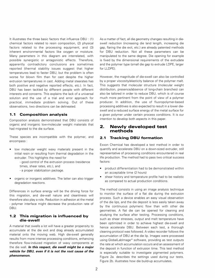
A formulation based on an LLDPE resin (0.5 MI, 0.918 g/cm3) was prepared with 10% of a 60% TiO2 masterbatch. The TiO2
was a rutile type pigment produced by the chloride process. The pigment had a non - siloxane organic treatment incombination with Al2O3. The masterbatch was produced with a 13 MFI LDPE carrier. To investigate the influence of an extrastabilization package, 1000 ppm of a standard primary antioxidant was incorporated. Compounding of both control and PPA-containing samples was done with a HAAKE torque Rheometer using a Rheomix 3000 mixer with roller blades. The blendedresins were ground at ambient temperature prior to use in the capillary rheometer.
Figure 4Capillary Rheometrydata: LLDPE
Figure 4 represents the measured apparent shear stresses in function of the apparent shear rates. As one can notice, addingantioxidant has little to no impact on apparent shear stress, the PPA2 reduces the apparent shear stress by 25% and the PPA1even by 35%.
The results obtained with the MDPE resin were even more pronounced. Shear stress reductions of more than 50% have beenrecorded.
Table III gives an overview of the extrudate dimensions at different apparent shear rates for the LLDPE formulation. Die-swellindeed increases at elevated shear rates and is significantly reduced in the PPA-containing formulations due to reducedapparent shear stresses at equivalent apparent shear rates.
Apparent shear rate Control Control + PAO Control + PAO + PPA1 Control + PAO + PPA2(sec-1) (mm) (mm) (mm) (mm)
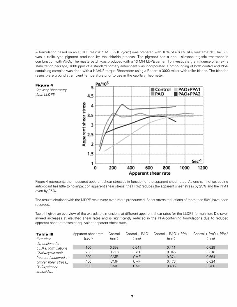
Since it has been demonstrated [2] that die-swell provides amedium for transporting low MW materials and pigmentstowards the die metal surface, die build-up obtained duringeach rheological screening was recorded by taking picturesof the die at the end of each session. Each session tookabout one hour evaluation time. Figure 5 shows significantdie build-up when extruding the pigmented MDPE. The useof a proper stabilization package reduces the amount of die
build-up due to a reduced flow of degraded materials. PPA1and PPA2 reduce the amount of die build-up even furtherdue to a reduced die-swell.
Also when evaluating the LLDPE formulations, PPA provedto be extremely efficient in reducing the amount of die build-up during the capillary rheometry session.
Figure 5Capillary Die picturesMDPE
MDPE control MDPE + PAO
MDPE + PAO + PPA1 MDPE + PAO + PPA2
8
98-0504-1105-1.qxd 1/16/01 2:20 PM Page 10
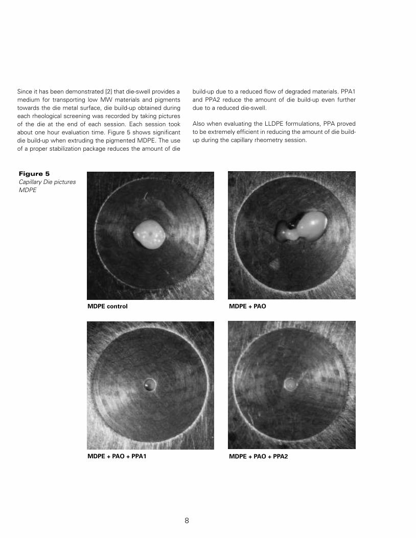
Figure 6(a)Z-N LLDPE,2 hours extrusion
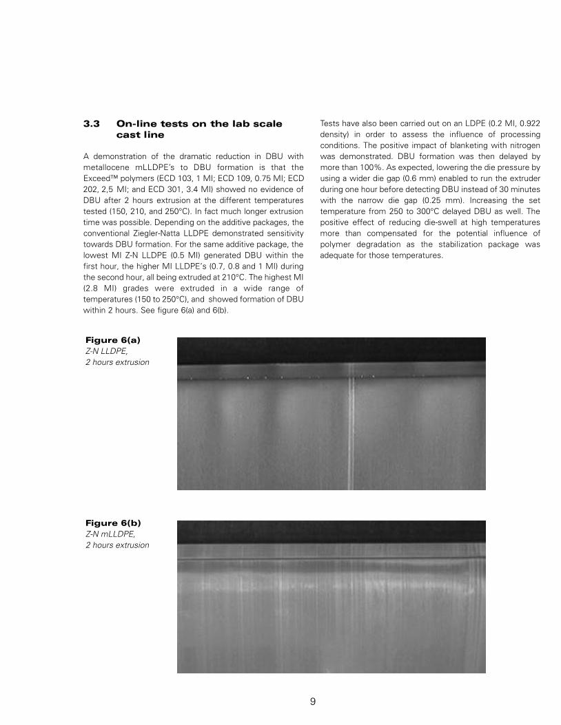
Figure 6(b)Z-N mLLDPE,2 hours extrusion
3 . 3 On-line tests on the lab scale cast line
A demonstration of the dramatic reduction in DBU withmetallocene mLLDPE’s to DBU formation is that theExceed™ polymers (ECD 103, 1 MI; ECD 109, 0.75 MI; ECD202, 2,5 MI; and ECD 301, 3.4 MI) showed no evidence ofDBU after 2 hours extrusion at the different temperaturestested (150, 210, and 250°C). In fact much longer extrusiontime was possible. Depending on the additive packages, theconventional Ziegler-Natta LLDPE demonstrated sensitivitytowards DBU formation. For the same additive package, thelowest MI Z-N LLDPE (0.5 MI) generated DBU within thefirst hour, the higher MI LLDPE’s (0.7, 0.8 and 1 MI) duringthe second hour, all being extruded at 210°C. The highest MI(2.8 MI) grades were extruded in a wide range oftemperatures (150 to 250°C), and showed formation of DBUwithin 2 hours. See figure 6(a) and 6(b).
Tests have also been carried out on an LDPE (0.2 MI, 0.922density) in order to assess the influence of processingconditions. The positive impact of blanketing with nitrogenwas demonstrated. DBU formation was then delayed bymore than 100%. As expected, lowering the die pressure byusing a wider die gap (0.6 mm) enabled to run the extruderduring one hour before detecting DBU instead of 30 minuteswith the narrow die gap (0.25 mm). Increasing the settemperature from 250 to 300°C delayed DBU as well. Thepositive effect of reducing die-swell at high temperaturesm o re than compensated for the potential influence ofpolymer degradation as the stabilization package wasadequate for those temperatures.
9
98-0504-1105-1.qxd 1/16/01 2:20 PM Page 11
The detrimental effect of moisture has also been verified,since DBU was noticed after 20 minutes when extrudingLDPE stored in a highly humid environment, whereas DBUwas formed after 45 minutes after drying the polymer. Thiseffect was even more pronounced in the case of antiblockadditivated LDPE.
The best use of the test method is demonstrated withpigmented polymers. To exaggerate the effects, tests weredone adding 30% of different white MB's in a 0.75 MI LDPE.DBU was generated after a few to 15 minutes for thecommodity MB’s and only after 1 hour for a "speciallydeveloped low die build-up" MB.
Also the effect of PPA was evaluated on the down-sized castline. The improvement in extrusion performance upon theintroduction of PPA additives suggested by the capillaryrheometer measurements was verified by running thedifferent formulations described in Table II. The Controlformulation has been seen to give DBU problems at acustomer’s facilities. On the Collin film line, initial DBU wasrecorded after 5 minutes. Further stabilization of the blend(control + PAO) enabled to run 30 minutes without DBU.Finally, the combination of antioxidant and PPA1 did notshow any die build-up after two hours processing. For thesecomparisons a narrow die gap was maintained.
Figure 7(a)LLDPE + TiO2 (6%)
Figure 7(b)LLDPE + TiO2 (6%) +PPA-2 (600 ppm)
The method was also successfully applied on pigmented LDPE, MDPE and PP.
10
98-0504-1105-1.qxd 1/16/01 2:20 PM Page 12
4. ConclusionA sensitive method has been developed in order toreproduce and quantify die build-up formation. The methodhelped us in confirming die-swell as a major vehicle of diebuild-up, suggesting therefore several viable routes in orderto minimize the criticality of DBU issues in processingoperations.
As compared to traditional Ziegler-Natta products, the newmetallocene mLLDPE‘s (Exceed™) are characterized bynarrow molecular weight distribution. Therefore, they showa much reduced melt elasticity at a comparable MI, whichresults in a low die-swell. In addition, this narrow MWDimplies a very small fraction of low molecular weight waxymaterials (as an example, 0.71% of hexane extractableswere measured for ECD 103 versus 2.8% for a Z-N LLDPEof similar molecular weight and density). Finally, beingproduced with an efficient and chemically different catalysttechnology, they do not require catalyst neutralizer. All theseelements contribute to DBU reduction.
The use of appropriate fluoro p o l y m e r-based pro c e s s i n gadditives is an efficient way to minimize DBU. First, suchadditives migrate to the wall surface, creating a thin layerthat favors polymer slip. At a given throughput, this resultsin a reduction of the stress level, and therefore die-swell aswell. Furthermore, the fluoropolymer coating reduces thesurface energy of the die wall. Thus, degraded materials andpigments have less propensity to adhere to the metalsurface. Together with die swell reduction, the low surfaceenergy will also promote efficient DBU reduction.
11
98-0504-1105-1.qxd 1/16/01 2:20 PM Page 13
5. Appendix 1: References
1. T. Blong, D. Klein, A.V. Pocius, M.A. Strobel, 'Theinfluence of polymer processing additives on the surface,mechanical, and optical properties of LLDPE Blown Film'TAPPI ‘93 PLC conference.
2. I. Klein, 'Die drool : What causes it, how to avoid it',Plastics World, May 1981.
3. J.D. Gander, A.J. Giacomin, 'Review of die build-up inplastics extrusion' ANTEC ‘96.
4. G. Kress, Kunststoffe, 'Striation on tubular films -Influence on flow channel surfaces' Vol. 65, August 1975.
6. D.E. Priester, 'The effect of die surface characteristics onprocessing additive performance', ANTEC '94.
7. C.M. Chan, 'Viscosity and the formation of die-drool atthe polymer-metal interfaces' International PolymerProcessing, Vol. 10, 1995.
8. R.I. Tanner, 'Recoverable elastic strain and swelling ratio',in Rheological Measurement, Ed. A.A. Collyer and D.W.Clegg, Elsevier applied Science.
9. H.M. Laun, 'Predictions of elastic strain of polymer meltsin shear and elongation' Journal of Rheology, Vol. 30,1986.
10. J.A. Brydson, 'Flow Pro p e rties of Polymer Melts',Second edition. George Godwin Limited in associationwith the Plastics and Rubber Institute.
12
98-0504-1105-1.qxd 1/16/01 2:20 PM Page 14
Technical Information and Test DataTechnical information, test data, and advice provided by Dyneon personnel are based on inform a-tion and tests we believe are reliable and are intended for persons with knowledge and technicalskills sufficient to analyze test types and conditions, and to handle and use raw polymers and re l a t-ed compounding ingredients. No license under any Dyneon or third party intellectual rights is grant-ed or implied by virtue of this inform a t i o n .
Important Notice:Because conditions of product use areoutside Dyneon’s control and vary widely,user must evaluate and determine whethera Dyneon product will be suitable for user’sintended application before using it. T h efollowing is made in lieu of all expre s sand implied warranties (including war-r a n t i e s of merchantability and fitnessfor a part i c u l a r purpose): If a Dyneonp roduct is proved to be defective,Dyneon‘s only obligation, and user’sonly re m e d y, will be, at D y n e o n ‘ soption, to replace the quantity of pro d-uct shown to be defective when userreceived it or to refund user’s purc h a s eprice. In no event will Dyneon be liablefor any direct, i n d i re c t , special, inciden-tal, or consequential loss or damage,re g a rdless of legal theory, such asb reach of w a rranty or contract, negli-gence, or strict liability.
This paper was prepared for presentation at PolyEthylene ‘97World Congress organized by MaackBusiness Services in Milano, Italy.
The Exxon Chemical emblem, the Interlocking X device, Exxpol,Exceed and Exxon are trademarks of Exxon Corporation.
98-0504-1105-1.qxd 1/16/01 2:20 PM Page 16
Warranty, Limited Remedy, and Disclaimer: Many factors beyond 3M’s control and uniquely within user’s knowledge and control can affect the use and performance of a 3M product in a particular application. User is solely responsible for evaluating the 3M product and determining whether it is fit for a particular purpose and suitable for user’s method of application. Unless a different warranty is specifically stated in the applicable product literature or packaging insert, 3M warrants that each 3M product meets the applicable 3M product specification at the time 3M ships the product. 3M MAKES NO OTHER WARRANTIES OR CONDITIONS, EXPRESS OR IMPLIED, INCLUDING, BUT NOT LIMITED TO, ANY IMPLIED WARRANTY OR CONDITION OF MERCHANTABILITY OR FITNESS FOR A PARTICULAR PURPOSE OR ANY IMPLIED WARRANTY OR CONDITION ARISING OUT OF A COURSE OF DEALING, CUSTOM OR USAGE OF TRADE. If the 3M product does not conform to this warranty, then the sole and exclusive remedy is, at 3M’s option, replacement of the 3M product or refund of the purchase price. Limitation of Liability: Except where prohibited by law, 3M will not be liable for any loss or damages arising from the 3M product, whether direct, indirect, special, incidental or consequential, regardless of the legal theory asserted, including warranty, contract, negligence or strict liability. Technical Information: Technical information, recommendations, and other statements contained in this document or provided by 3M personnel are based on tests or experience that 3M believes are reliable, but the accuracy or completeness of such information is not guaranteed. Such information is intended for persons with knowledge and technical skills sufficient to assess and apply their own informed judgment to the information. No license under any 3M or third party intellectual property rights is granted or implied with this information.
3M Center St. Paul, MN 55144-1000 1-800-810-8499 www.3M.com/fluoropolymers