This technical paper was written and developed in August, 2001 when the author(s) was an employee of Dyneon LLC. Dyneon LLC was formerly a wholly-owned subsidiary of 3M Company and was fully integrated into 3M Company on January 1, 2011. Title: Effect of MWD on the Amount of Polymer Process Additive (PPA) Required to Suppress Sharkskin Melt Fracture in LLDPE Abstract: It has recently been reported1 (TAPPI-2000) that different types of High-Performance Hexene LLDPE (HPH-LLDPE) behave differently with respect to the onset of sharkskin-melt-fracture (SSMF), depending on the breadth of the molecular weight distribution (MWD). The MWD differences were small and subtle, but the effect on the onset of melt fracture was significant. The present study is a continuation of that work, through a comparative investigation under shear rate conditions high enough to induce melt fracture in both narrow and broad-MWD LLDPEs. A polymer processing additive (PPA) was then added in stepwise increments in order to eliminate melt fracture. It was found that the narrow-MWD resin required more than twice the amount of PPA in order to eliminate SSMF. Date Published: August, 2001
Transcript
This technical paper was written and developed in August, 2001 when the author(s) was an employee of Dyneon LLC. Dyneon LLC was formerly a wholly-owned subsidiary of 3M Company and was fully integrated into 3M Company on January 1, 2011. Title: Effect of MWD on the Amount of Polymer Process Additive (PPA) Required to Suppress Sharkskin Melt Fracture in LLDPE Abstract: It has recently been reported1 (TAPPI-2000) that different types of High-Performance Hexene LLDPE
(HPH-LLDPE) behave differently with respect to the onset of sharkskin-melt-fracture (SSMF),
depending on the breadth of the molecular weight distribution (MWD). The MWD differences were small and subtle, but the effect on the onset of melt fracture was significant. The present study is a continuation of that work, through a comparative investigation under shear rate conditions high enough to induce melt fracture in both narrow and broad-MWD LLDPEs. A polymer processing additive (PPA) was then added in stepwise increments in order to eliminate melt fracture. It was found that the narrow-MWD resin required more than twice the amount of PPA in order to eliminate SSMF.
Date Published: August, 2001
Dynamar™
Polymer Processing Additives
Effect of MWD on the Amount of PolymerProcess Additive (PPA) Required to
Suppress Sharkskin Melt Fracture in LLDPE
Harry Mavridis Equistar Chemicals, LP
Kirsten FronekDyneon LLC
No.35
ABSTRACT
It has recently been reported1 (TAPPI-2000) that differenttypes of High-Performance Hexene LLDPE (HPH-LLDPE)behave differently with respect to the onset of sharkskin-melt-fracture (SSMF), depending on the breadth of the molecularweight distribution (MWD). The MWD differences weresmall and subtle, but the effect on the onset of melt fracturewas significant. The present study is a continuation of thatwork, through a comparative investigation under shear rateconditions high enough to induce melt fracture in both narrowand broad-MWD LLDPEs. A polymer processing additive(PPA) was then added in stepwise increments in order toeliminate melt fracture. It was found that the narrow-MWDresin required more than twice the amount of PPA in order toeliminate SSMF.
INTRODUCTION
There have been significant developments in recent years inthe area of hexene-LLDPE resins for film applications. Thecommon characteristic of the new hexene-LLDPE resins isthat they achieve significant enhancement in film strengthproperties. There are, however, subtle differences betweenthe commercially available High-Performance Hexene LLDPEsthat can translate to different extrusion or film performancebehavior. In a recent paper1, the relative behavior of twofamilies of HPH-LLDPEs with respect to SSMF wasinvestigated via blown film extrusion and capillary rheologyexperiments. The broader-MWD HPH showed no signs ofSSMF within the range of blown film conditions studied,whereas the narrower-MWD HPH showed severe SSMFwithin the same range of processing conditions. Film impactstrength, as measured by dart drop, was shown to be verysensitive to SSMF and was reduced drastically by SSMF,whereas capillary rheology seemed less effective indistinguishing relatively small differences in SSMF tendencyThe present study is a continuation of the earlier work1,through a comparative investigation under shear rateconditions high enough to induce melt fracture in both narrowand broad-MWD LLDPEs. A PPA was then added in stepwiseincrements in order to eliminate melt fracture. PPAs are usedin blown film extrusion to eliminate melt fracture and provideother extrusion benefits such as throughput improvement, gelreduction and die build-up reduction2. The objective of thisstudy was to determine the amount of fluoropolymer PPArequired to suppress SSMF and how this amount may beinfluenced by the breadth of the MWD.
EXPERIMENTAL
Materials
The LLDPE resins studied are listed in Table I. Samples A and B are commercially available, high-performance hexene-
LLDPE, tradenamed Petrothene Select™, describedelsewhere3. Sample A and Sample B are both of thePetrothene Select™-type, the only difference being in theMelt Index. Sample C is a narrower-MWD, high-performancehexene-LLDPE. The fluoropolymer PPA is Dynamar™ FX 5920Aand was added as a 3% masterbatch in 2 MI LLDPE.
Melt Fracture Evaluations
Equipment. As in similar studies from the Dyneon laboratory4,melt fracture evaluations were performed on a Kiefel blownfilm line, equipped with a 1.6 in (40mm) grooved feed extruder(24:1 L/D) and a 1.6 in (40mm) die with a 0.024 in (0.6mm) diegap. Target melt temperature is 204.4°C (400°F) and bothextruder and die zones are set at 204.4°C (400°F). The outputrate is 28 lb/hr (12.7 Kg/hr), which translates to shear rate atthe die gap of approximately 600 sec-1. BUR, layflat and take-off speed are 1.6, 8.5 in and 40 ft/min (1.6, 21.6 cm and12.2m/min), respectively.
General procedure. Film line formulations were prepared bytumble blending the LLDPE resin with the appropriate amountof the PPA masterbatch on a pail tumbler for a minimum of 10minutes before charging to the film line extruder. For the PPAminimum level experiments, the initial PPA level tested waschosen so as to have the initial level too low to completelyeliminate melt fracture within one hour. Before each run thefilm line was purged with a 70% calcium carbonate in LDPEpurge compound followed by a neat LLDPE film resin.Throughout the trial the film line conditions were recorded andfilm samples taken every 15 minutes. To measure the amountof melt fracture in a film sample, a sample of the layflat wasplaced on an overhead projector to project the image onto alarger surface. The melt fracture was recorded as apercentage of the layflat.
PPA minimum level studies. To determine the minimumlevel of PPA needed to eliminate melt fracture, the followingprocedure was followed in all cases:
1. Establish base line conditions with the base resin sample. Run for at least 1 hour to establish 100% melt fracture andsteady baseline gate pressure.
2. Charge resin sample containing 400 ppm PPA. Run for 1 hour.
3. If melt fracture is not eliminated in the previous step,increase PPA level by 100 or 200 ppm, depending on theamount of melt fracture remaining, and run that conditionfor one hour.
4. Repeat step 3, increasing PPA level by at least 100 ppmuntil melt fracture is completely eliminated.
5. Purge the line and continue the procedure with the next sample.
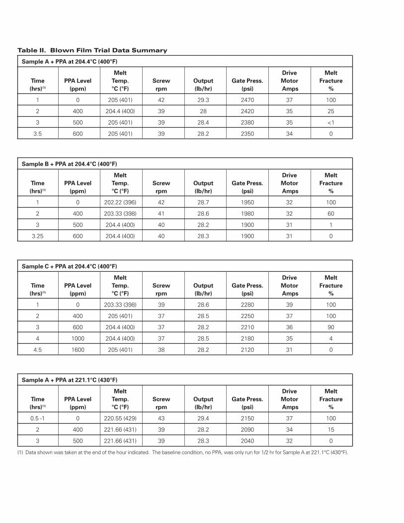
A summary of the blown film trial data can be found in Table II.
1
2
RESULTS AND DISCUSSION
Resin Structure and Melt Fracture Tendency
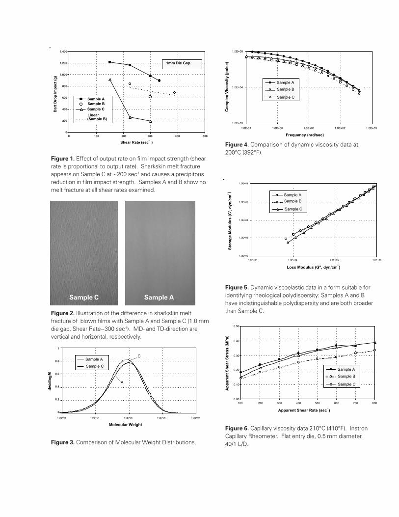
Past work1 with the resins of the present study showed asubstantial difference in melt fracture tendency. Under thefilm fabrication conditions of Ref.[1], Samples A & B showedno melt fracture, whereas Sample C showed severe meltfracture once the shear rate exceeded ~200 sec-1, for a die gapof 1.0 mm (0.040”). The effect of sharkskin melt fracture ismost dramatically evident on the film impact strength, asmeasured by Dart Drop. Fig.1, taken from Ref.[1], shows acomparison of film impact data for the three resins of thepresent study. It is clearly evident that with Sample C there isa transition around ~200 sec-1, at which the Dart Drop impactstrength suffers a precipitous reduction. No such transitioncan be seen in the data of Samples A & B. A visualcomparison of Samples A & C at a shear rate of 300 sec-1 isgiven in Fig.2.
The difference in molecular structure responsible for theobserved difference in melt fracture tendency is believed tobe the breadth of MWD, as Fig.3 shows. Other additives thatmay interfere with melt fracture, such as antiblock orstearates5-8, are listed in Table I and are shown to be atcomparable levels for all three samples. Samples A and Bhave similar MWD, the only difference being a slightdifference in average molecular weight (reflected in thedifferent Melt Index). Sample C has a slightly narrower MWDand a Melt Index intermediate between that of Samples A & B.
The differences in MWD are directly reflected in therheological properties, as Figs.4-6 show. Specifically, Fig.5 is arepresentation of the rheological data designed9 to normalizeout the molecular weight effect and only show MWDdifferences (broader MWD corresponding to higher G’, alsoquantified in the ER value of Table I. The ER and PDRnumbers listed in Table I, are measures of rheologicalpolydispersity, as shown and discussed in Ref.[9]). As Fig.5shows, Samples A&B are virtually indistinguishable, whereasSample C is narrower, in agreement with Fig.3.
It is also important to examine the capillary viscosity data overthe range of shear rates used in the melt fracture eliminationstudies (Fig.6). It can be seen that Sample A has the highestviscosity at all shear rates, followed closely by Sample C. Thisranking of viscosities is relevant to the criterion of the onset ofsharkskin melt fracture. It has been suggested that meltfracture sets in at a critical value of shear stress. If this criticalshear stress were a universal parameter, independent ofMWD, we would expect the following order in melt fracturetendency: A~ C >>B, with A having the worst melt fracturetendency. The results below are clearly in disagreement withsuch an order and therefore the critical shear stress mustdepend on MWD.
Melt Fracture Elimination Studies
Following the procedure outlined in the experimental section,we were able to establish 100% melt fracture with all three(A, B and C) base resins at the run conditions selected;204.4°C (400°F) and 600 s-1. The resin samples did varyhowever in the degree of melt fracture. At the baselineconditions, without processing additive, Sample C had thesharpest, most well defined melt fracture pattern, followed byA and then B which showed the softest melt fracture eventhough it covered 100% of the layflat. Sample A run at a melttemperature of 221.1°C (430°F) had a slightly softer meltfracture pattern than when run at 204.4°C (400°F).
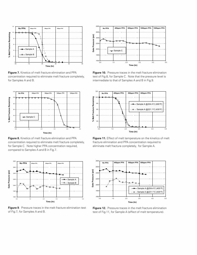
Once the PPA processing additive was added to the resin, itappeared to clear melt fracture slightly faster in Sample A thanin Sample B although total elimination of melt fractureoccurred essentially at the same time and level of processingadditive, clearing between 3 and 3 1/2 hours and at 600 ppmPPA (Fig.7). The response to processing additive wassignificantly different in Sample C. Although 600 ppm PPAwas sufficient to clear Samples A and B, at 600 ppm PPA theSample C film still had 90% melt fracture remaining at the endof the hour. At 1000 ppm the film still had 4% melt fractureremaining. After running the 1000 ppm condition, we had onlyenough Sample C to run one more level of processingadditive, so we increased the PPA level to 1600 ppm. At 1600ppm PPA the melt fracture was quickly eliminated so theactual minimum level to clear melt fracture is probablybetween 1000 and 1600 ppm PPA (Fig.8).
Gate pressures of the resins were also recorded. Sample Ahad the highest baseline gate pressure followed by C,whereas Sample B had the lowest gate pressure (see Figs.9-10). Therefore the average wall shear stress for Sample C isintermediate to that of Samples A and B and yet Sample C hadthe worst melt fracture. It would appear that the criterion of acritical shear stress for onset of melt fracture is not universallyvalid, or at least that it shows a MWD-dependence.
Finally, melt temperature appeared to have little effect on PPAperformance in Sample A. Although the baseline melt fracturewas slightly softer at 221.1°C (430°F) than at 204.4°C (400°F)the rate of melt fracture elimination was not significantlydifferent (Fig.11). In other resin systems evaluated at Dyneonwe have observed that by running at lower temperatures theprocessing additive sometimes provides larger pressurereduction over the base condition than running withprocessing additive at higher temperatures2. That was notevident in this trial as indicated by the overall pressurereductions at 204.4°C (400°F) and 221.1°C (430°F), Fig.12.
3
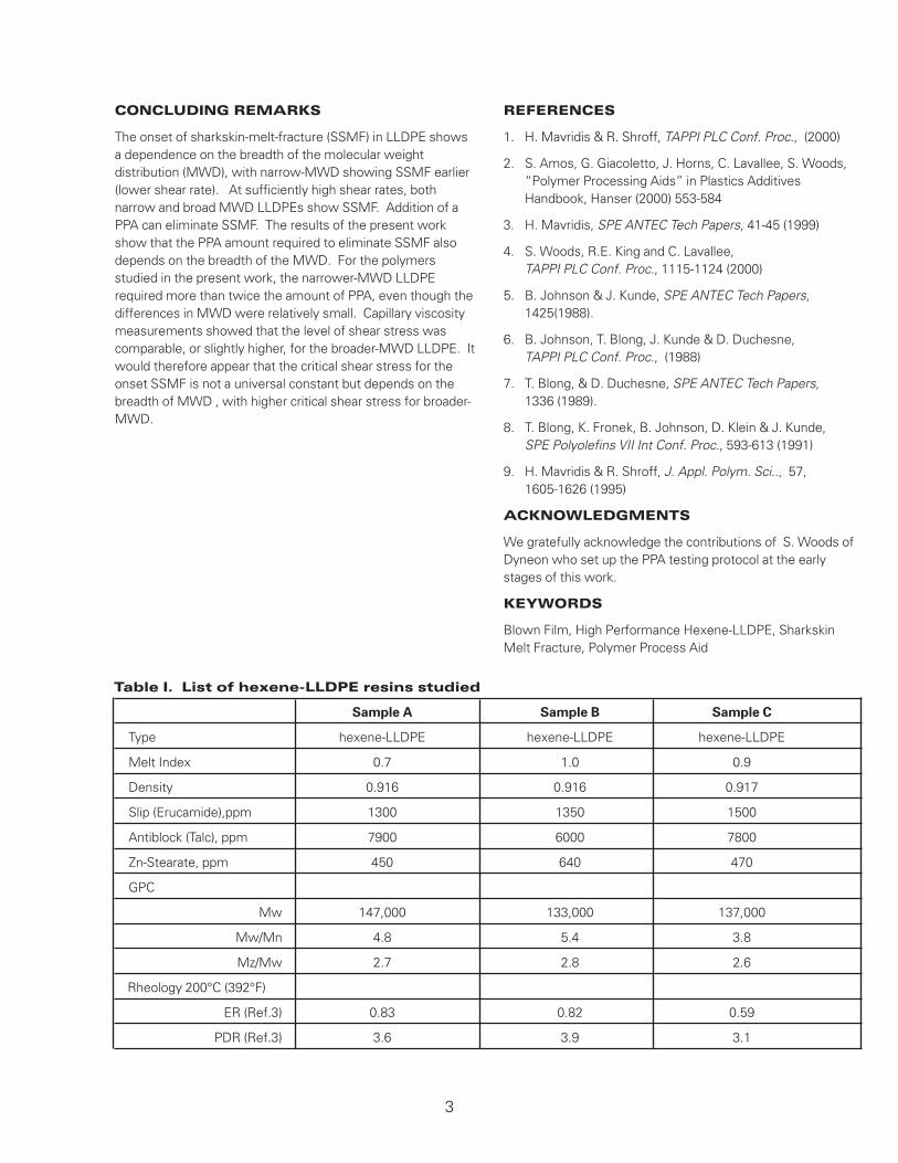
CONCLUDING REMARKS
The onset of sharkskin-melt-fracture (SSMF) in LLDPE showsa dependence on the breadth of the molecular weightdistribution (MWD), with narrow-MWD showing SSMF earlier(lower shear rate). At sufficiently high shear rates, bothnarrow and broad MWD LLDPEs show SSMF. Addition of aPPA can eliminate SSMF. The results of the present workshow that the PPA amount required to eliminate SSMF alsodepends on the breadth of the MWD. For the polymersstudied in the present work, the narrower-MWD LLDPErequired more than twice the amount of PPA, even though thedifferences in MWD were relatively small. Capillary viscositymeasurements showed that the level of shear stress wascomparable, or slightly higher, for the broader-MWD LLDPE. Itwould therefore appear that the critical shear stress for theonset SSMF is not a universal constant but depends on thebreadth of MWD , with higher critical shear stress for broader-MWD.
REFERENCES
1. H. Mavridis & R. Shroff, TAPPI PLC Conf. Proc., (2000)
2. S. Amos, G. Giacoletto, J. Horns, C. Lavallee, S. Woods, “Polymer Processing Aids” in Plastics Additives Handbook, Hanser (2000) 553-584
3. H. Mavridis, SPE ANTEC Tech Papers, 41-45 (1999)
4. S. Woods, R.E. King and C. Lavallee, TAPPI PLC Conf. Proc., 1115-1124 (2000)
5. B. Johnson & J. Kunde, SPE ANTEC Tech Papers,1425(1988).
6. B. Johnson, T. Blong, J. Kunde & D. Duchesne, TAPPI PLC Conf. Proc., (1988)
7. T. Blong, & D. Duchesne, SPE ANTEC Tech Papers, 1336 (1989).
8. T. Blong, K. Fronek, B. Johnson, D. Klein & J. Kunde, SPE Polyolefins VII Int Conf. Proc., 593-613 (1991)
9. H. Mavridis & R. Shroff, J. Appl. Polym. Sci.., 57, 1605-1626 (1995)
ACKNOWLEDGMENTS
We gratefully acknowledge the contributions of S. Woods ofDyneon who set up the PPA testing protocol at the earlystages of this work.
KEYWORDS
Blown Film, High Performance Hexene-LLDPE, SharkskinMelt Fracture, Polymer Process Aid
Table I. List of hexene-LLDPE resins studied
Sample A Sample B Sample C
Type hexene-LLDPE hexene-LLDPE hexene-LLDPE
Melt Index 0.7 1.0 0.9
Density 0.916 0.916 0.917
Slip (Erucamide),ppm 1300 1350 1500
Antiblock (Talc), ppm 7900 6000 7800
Zn-Stearate, ppm 450 640 470
GPC
Mw 147,000 133,000 137,000
Mw/Mn 4.8 5.4 3.8
Mz/Mw 2.7 2.8 2.6
Rheology 200°C (392°F)
ER (Ref.3) 0.83 0.82 0.59
PDR (Ref.3) 3.6 3.9 3.1
Table II. Blown Film Trial Data Summary
Sample A + PPA at 204.4°C (400°F)
Melt Drive Melt
Time PPA Level Temp. Screw Output Gate Press. Motor Fracture
(hrs)(1) (ppm) °C (°F) rpm (lb/hr) (psi) Amps %
1 0 205 (401) 42 29.3 2470 37 100
2 400 204.4 (400) 39 28 2420 35 25
3 500 205 (401) 39 28.4 2380 35 <1
3.5 600 205 (401) 39 28.2 2350 34 0
Sample B + PPA at 204.4°C (400°F)
Melt Drive Melt
Time PPA Level Temp. Screw Output Gate Press. Motor Fracture
(hrs)(1) (ppm) °C (°F) rpm (lb/hr) (psi) Amps %
1 0 202.22 (396) 42 28.7 1950 32 100
2 400 203.33 (398) 41 28.6 1980 32 60
3 500 204.4 (400) 40 28.2 1900 31 1
3.25 600 204.4 (400) 40 28.3 1900 31 0
Sample C + PPA at 204.4°C (400°F)
Melt Drive Melt
Time PPA Level Temp. Screw Output Gate Press. Motor Fracture
(hrs)(1) (ppm) °C (°F) rpm (lb/hr) (psi) Amps %
1 0 203.33 (398) 39 28.6 2280 39 100
2 400 205 (401) 37 28.5 2250 37 100
3 600 204.4 (400) 37 28.2 2210 36 90
4 1000 204.4 (400) 37 28.5 2180 35 4
4.5 1600 205 (401) 38 28.2 2120 31 0
Sample A + PPA at 221.1°C (430°F)
Melt Drive Melt
Time PPA Level Temp. Screw Output Gate Press. Motor Fracture
(hrs)(1) (ppm) °C (°F) rpm (lb/hr) (psi) Amps %
0.5 -1 0 220.55 (429) 43 29.4 2150 37 100
2 400 221.66 (431) 39 28.2 2090 34 15
3 500 221.66 (431) 39 28.3 2040 32 0
(1) Data shown was taken at the end of the hour indicated. The baseline condition, no PPA, was only run for 1/2 hr for Sample A at 221.1°C (430°F).
Figure 1. Effect of output rate on film impact strength (shearrate is proportional to output rate). Sharkskin melt fractureappears on Sample C at ~200 sec-1 and causes a precipitousreduction in film impact strength. Samples A and B show nomelt fracture at all shear rates examined.
Figure 2. Illustration of the difference in sharkskin meltfracture of blown films with Sample A and Sample C (1.0 mmdie gap, Shear Rate~300 sec-1). MD- and TD-direction arevertical and horizontal, respectively.
Figure 3. Comparison of Molecular Weight Distributions.
1,400
1,200
1,000
800
600
400
200
00 100 200 300 400 500
1.0E+03
1.0E+04
1.0E+05
1.0E-01 1.0E+00 1.0E+01 1.0E+02 1.0E+03
Frequency (rad/sec)
Sample A
Sample B
Sample C
Co
mp
lex
Vis
cosi
ty (
po
ise)
1
0.8
0.6
0.4
0.2
0
Figure 4. Comparison of dynamic viscosity data at200°C (392°F).
Figure 5. Dynamic viscoelastic data in a form suitable foridentifying rheological polydispersity: Samples A and Bhave indistinguishable polydispersity and are both broaderthan Sample C.
Figure 6. Capillary viscosity data 210°C (410°F). InstronCapillary Rheometer. Flat entry die, 0.5 mm diameter, 40/1 L/D.
Sample C Sample A
Figure 7. Kinetics of melt fracture elimination and PPAconcentration required to eliminate melt fracture completely,for Samples A and B.
Figure 8. Kinetics of melt fracture elimination and PPAconcentration required to eliminate melt fracture completely,for Sample C. Note higher PPA concentration required,compared to Samples A and B in Fig.7.
Figure 9. Pressure traces in the melt fracture elimination testof Fig.7, for Samples A and B.
Figure 10. Pressure traces in the melt fracture eliminationtest of Fig.8, for Sample C. Note that the pressure level isintermediate to that of Samples A and B in Fig.9.
Figure 11. Effect of melt temperature on the kinetics of meltfracture elimination and PPA concentration required toeliminate melt fracture completely, for Sample A.
Figure 12. Pressure traces in the melt fracture eliminationtest of Fig.11, for Sample A (effect of melt temperature).
1600
1800
2000
2200
2400
2600
2800
0.0 1.0 2.0 3.0 4.0 5.0
Time (hr)
Sample C
No PPA 400ppm PPA 600ppm PPA 1000ppm PPA 1600ppm PPA
Gat
e P
ress
ure
(p
si)
0
20
40
60
80
100
120
0.0 1.0 2.0 3.0 4.0 5.0
Time (hr)
% M
elt
Fra
ctu
re R
emai
nin
g
Sample A @204.4°C (400°F)
Sample A @221.1°C (430°F)
No PPA 400ppm PPA 500ppm PPA 600ppm PPA
1600
1800
2000
2200
2400
2600
2800
0.0 1.0 2.0 3.0 4.0 5.0
Time (hr)
Sample A @204.4°C (400°F)
Sample A @221.1°C (430°F)
No PPA 400ppm PPA 500ppm PPA 600ppm PPA
Gat
e P
ress
ure
(p
si)
Technical Information and Test DataTechnical information, test data, and advice provided by Dyneon personnel are based on informationand tests we believe are reliable and are intended for persons with knowledge and technical skillssufficient to analyze test types and conditions, and to handle and use raw polymers and relatedcompounding ingredients. No license under any Dyneon or third party intellectual rights is granted orimplied by virtue of this information.
Presented at TAPPI PLC 2001 Polymers, Laminations and Coatings Conference August 2001 San Diego, California
Important Notice:Because conditions of product use areoutside Dyneon’s control and vary widely,user must evaluate and determine whether aDyneon product will be suitable for user’sintended application before using it. Thefollowing is made in lieu of all expressand implied warranties (includingwarranties of merchantability and fitnessfor a particular purpose): If a Dyneonproduct is proved to be defective,Dyneon‘s only obligation, and user’sonly remedy, will be, at Dyneon‘s option,to replace the quantity of product shownto be defective when user received it orto refund user’s purchase price. In noevent will Dyneon be liable for any direct,indirect, special, incidental, orconsequential loss or damage,regardless of legal theory, such asbreach of warranty or contract,negligence, or strict liability.
3M BrazilVia Anhanguera, km, 110Sumare, San PauloCEP 13181-900Phone: +55 19864 7000Fax:+55 3838 6606
www.dyneon.com
Dynamar and Dyneon are trademarks of Dyneon
Warranty, Limited Remedy, and Disclaimer: Many factors beyond 3M’s control and uniquely within user’s knowledge and control can affect the use and performance of a 3M
product in a particular application. User is solely responsible for evaluating the 3M product and determining whether it is fit for a particular purpose and suitable for user’s method of application. Unless a different warranty is specifically stated in the applicable product literature or packaging insert, 3M warrants that each 3M product meets the applicable 3M product specification at the time 3M ships the product. 3M MAKES NO OTHER WARRANTIES OR CONDITIONS, EXPRESS OR IMPLIED, INCLUDING, BUT NOT LIMITED TO, ANY IMPLIED WARRANTY OR CONDITION OF MERCHANTABILITY OR FITNESS FOR A PARTICULAR PURPOSE OR ANY IMPLIED WARRANTY OR CONDITION ARISING OUT OF A COURSE OF DEALING, CUSTOM OR USAGE OF TRADE. If the 3M product does not conform to this warranty, then the sole and exclusive remedy is, at 3M’s option, replacement of the 3M product or refund of the purchase price. Limitation of Liability: Except where prohibited by law, 3M will not be liable for any loss or damages arising from the 3M product, whether direct, indirect, special, incidental or consequential, regardless of the legal theory asserted, including warranty, contract, negligence or strict liability. Technical Information: Technical information, recommendations, and other statements contained in this document or provided by 3M personnel are based on tests or
experience that 3M believes are reliable, but the accuracy or completeness of such information is not guaranteed. Such information is intended for persons with knowledge and technical skills sufficient to assess and apply their own informed judgment to the information. No license under any 3M or third party intellectual property rights is granted or implied with this information.
3M Center St. Paul, MN 55144-1000 1-800-810-8499 www.3M.com/fluoropolymers