12
Third Party Testing Summaries of Aluminum Fittings Refrigeration Press Fittings
Third Party Testing Summaries of Aluminum Fittings
Refrigeration Press Fittings

Table of Contents
Overview .....................................................................3
Freeze/Thaw Cycling ..................................................4
Accelerated Thermal Cycling .....................................6
Mechanical Vibration ..................................................8
Time and Motion ......................................................10
Testing Summary ......................................................11
Refrigeration Press Fittings
2

RLS® Aluminum Refrigeration Press Fittings Overview
3
When aluminum refrigeration tube is installed (just like copper tube), it is typically connected with brazed joints. While brazed joints are usually strong and reliable, the process of brazing is highly technical, time consuming and potentially hazardous due to the presence of an open flame.
The challenges that come with making consistent and reliable brazed aluminum joints have kept many manufacturers from choosing lower-cost and lighter-weight aluminum tube for their products. However, RLS now offers a truly simple, effective and economical way to make reliable, leak-free aluminum connections.
Proven RLS Press Technology RLS press fittings withstand the high pressures of refrigeration systems, and can be joined in a much shorter period of time than brazing, without a flame or heat source. The fittings are joined by pressing with an approved RLS press tool and press jaws, which are similar to existing water press connect tools, but are based on exclusive AVA Press Technology™ which was specifically developed for refrigeration systems.
The AVA Press Technology™ is combined with a hydrogenated nitrile (HNBR) O-ring. HNBR is widely known for its physical strength and retention of properties after long-term exposure to heat, oil and chemicals. HNBR has many automotive (A/C seals, hoses etc.) and industrial (heat exchangers, etc.) uses. In combination, the RLS press technology and the O-rings work together to create the best seals in the industry today.
Cross-section of a crimped RLS joint
O-ring
O-ring
Fast, Easy Connections Just like RLS Copper Press Fittings, the aluminum tube ends are prepped in the same way as brazing. Then it’s as easy as inserting the tube into the fitting and crimping with the RLS press tool and jaws. In a matter of seconds, a permanent and reliable mechanical joint is made — without the need for heat, flammable gas, hot work permits, nitrogen purging or highly skilled labor.
To prove the performance and durability of RLS fittings, a number of tests have been performed by third parties, which are described on the following pages.

Freeze/Thaw Cycling Test
Conducted by: Sharat Raj & Stefan Elbel, Creative Thermal Solutions
Overview
• The objective of this test was to determine if infiltration of water into the fitting and subsequent freezing and thawing of water compromises the integrity of the fitting’s seal to the atmosphere.
• A total of 5,000 freeze/thaw cycles were conducted to represent frosting/defrosting over a 10-year period in a typical heat pump system.
• The fittings were subjected to surface temperatures of -20°C in a humid environment to initiate condensation and freezing on the section.
• This was followed by pumping a warm solution of ethylene glycol and water (50/50% by volume) at 20°C to initiate thawing, and to make sure the surface temperatures of the fittings were above freezing.
• Temperatures were measured at the inlet of each fitting.
• Freezing and thawing on the fittings were confirmed by temperature measurement and visual observation.
Solenoids were used to switch the flow between hot and cold fluid. The cold bath was maintained at a lower temperature than the required fitting temperatures to account for the heat infiltration from the ambient.
Freeze/thaw cycling test schematic
Infrared images of the fittings during the freezing cycle
Freeze cycle Thaw cycle
4

Freeze/Thaw Cycling Test (continued)
Temperature measurements
• Temperatures were measured at the inlet of 12 test sections.
• Fitting sizes to be investigated:
3/8" – 2 samples
1/2" – 2 samples
5/8" – 2 samples
3/4" – 2 samples
7/8" – 2 samples
1 1/8" – 2 samples
• Data was recorded at 10 second intervals.
• The cycle time was set at 9 minutes.
Conclusions
• The aluminum RLS® fittings were subject to 5,000 freeze/thaw cycles over a 30 day period.
• From temperature measurements and confirmation by visual observation, noticeable ice formation and thawing occurred during each freeze thaw cycle.
• A leak test was conducted after 1,800 cycles, and no leakage from any fitting was observed.
• A final leak test was performed after the completion of 5,000 cycles.
– Leak test involved pressurizing the fitting to 475 psi, then using a leak testing fluid to check for leaks around the fittings.
– The fitting tree held constant pressure for 3 hours. The pressure was monitored using a pressure gauge, taking into account the ambient temperature.
• No leaks were observed at any of the fittings.
• The ice formation and thawing did not compromise the sealing capability of the fittings.
5
Conducted by: Sharat Raj & Stefan Elbel, Creative Thermal Solutions
Overview
• The objective of this test was to perform accelerated pressure-temperature cycles to simulate real life conditions experienced by the aluminum fittings in a R410A system.
• A total of 1 2 fittings in 6 different sizes were tested simultaneously by fabricating a fitting tree.
• These fittings were subjected to high temperatures and high pressures (heating mode), followed by low temperatures and low pressures (cooling mode) typically seen in a R410A system.
• An R410A vapor compression system was used as the support unit.
• The time taken for 1 cycle was kept between 60-90 seconds.
• During the heating mode, high side pressure and temperatures were approximately 3000 kPa and 65°C respectively.
• The heating mode was followed by a cooling mode where the pressure and temperature dropped to approximately 1400 kPa and 20°C respectively.
• The fittings were tested for 80,000 pressure-temperature cycles.
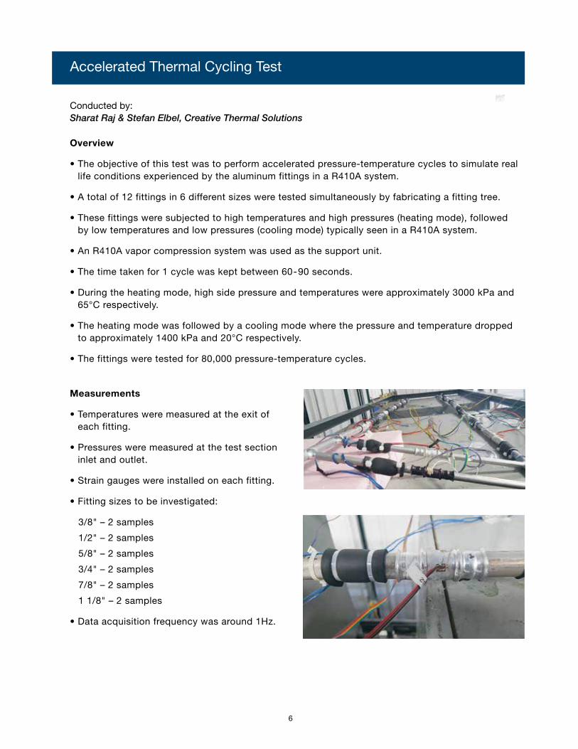
Measurements
• Temperatures were measured at the exit of each fitting.
• Pressures were measured at the test section inlet and outlet.
• Strain gauges were installed on each fitting.
• Fitting sizes to be investigated:
3/8" – 2 samples
1/2" – 2 samples
5/8" – 2 samples
3/4" – 2 samples
7/8" – 2 samples
1 1/8" – 2 samples
• Data acquisition frequency was around 1Hz.
Accelerated Thermal Cycling Test
6

Sample pressure-temperature response on 1.125" fitting
• The figures below show sample pressure and temperature responses for the 1.125" fitting.
• There was a rapid increase in pressure, followed by an increase in temperature during the heating mode. The system continued in heating mode until the temperature setpoint was reached.
• The heating mode was followed by a cooling mode, where there was a rapid drop in temperature and pressure. The system operated in cooling mode until the temperature setpoint was reached.
Conclusions
• The aluminum RLS® fittings were subjected to 80,000 pressure-temperature cycles over an 80 -day period.
• A weekly leak check was performed using leak checking fluid on the test sections.
• No leakage was observed by visual confirmation; the test rig performance over the duration of testing did not indicate any sign of refrigerant loss.
• A final leak check was performed at the end of the test period using nitrogen at 1000 kPa on the fitting tree. No leaks were observed on the fittings.
• The rapid pressure-temperature cycle did not compromise the sealing capability of the fittings at 80,000 cycles.
Time-line of testing
Date Number of cycles [-] Test status
03/07/2016 Test started No leakage
05/03/2016 40,000 cycles completed No leakage
05/23/2016 60,000 cycles completed No leakage
06/13/2016 80,000 cycles completed No leakage
Infrared profiles for 0.375" fittings in heating and cooling mode
7
Accelerated Thermal Cycling Test (continued)

Mechanical Vibration Test
Conducted by: Sharat Raj & Stefan Elbel, Creative Thermal Solutions
Overview
• The objective was to perform vibration testing of the RLS® Aluminum Press Fittings similar to UL testing procedures.
• This test was conceived to simulate field vibration in refrigerant carrying tubes.
• A series of 24 vibration tests were performed similar to those conducted earlier with copper RLS fittings.
• Tests were conducted on 6 fittings of varying diameters and tube lengths, with 4 samples per configuration.
• The fittings were subjected to 1.8 million cycles at an oscillating frequency of 16.6 Hz, with 1000 cycles per minute.
• The test sections were pressurized with nitrogen at 2750 kPa, and the pressure was monitored during the test to observe any failure during the test.
• Accelerometers were attached to the test fitting to measure the magnitude of acceleration.
Test facility with 0.875" fitting sample installed
Fittings and corresponding tube lengths
Tube outer diameter Tube length Number of samples
0.375" 12" 3
0.500" 18" 4
0.625" 18" 4
0.750" 18" 4
0.875" 24" 4
1.125" 24" 4
8

Conclusions
• The aluminum RLS fittings were subjected to 1.8 million vibration cycles during the test duration of 30 hours.
• All sizes of fitting samples passed the test without any failures. This was confirmed by the ability of the test section to hold pressure during the duration of the test.
Test assembly of 0.375" fittings Test assembly of 0.5" and larger size tubes
Summary of tests
Fitting size Number of samples Samples passed
0.375" 3 3
0.5" 4 4
0.625" 4 4
0.75" 4 4
0.875" 4 4
1.25" 4 4
9
Mechanical Vibration Test (continued)

Conducted by: Jay Peters, Principal Advisor, Codes and Standards International
Methodology:
A time study was conducted in a controlled environment, with two stations set up for joining aluminum refrigeration tube: one by brazing and one by making RLS® press connections. Two different installers were used, one very experienced in making brazed connections, and one very experienced in using the RLS press tool.
The two installers were timed independently making connections using various-size aluminum tube and fittings. Before timing began, tube was cut to length, and the ends were prepared for connection (as these procedures are the same for both connection methods). Three connections were timed for each size of tube/fitting for each installer, and the three times were averaged. The results are shown in the table below.
Time and Motion Test
Fitting Size 1/4” 5/8” 1-1/8”
Brazed Connection 41 sec 51 sec 2:12 min
RLS Connection 24 sec 24 sec 25 sec
% Time Savings 41% 52% 81%
Labor time for installing an aluminum coupling
Key Findings and Conclusions:
The time savings achieved while joining tube using RLS aluminum press fittings, compared to brazed connections, ranged from 41% on the smallest fittings to 81% on the largest. The average time savings over the fitting sizes was well over 50%. So, on average, RLS connections were made in less than half the time of brazing — and in less than one-quarter the time on the largest fitting size.
Based on the study, brazed connections take longer to complete than RLS fitting connections. When analyzing the installation techniques for both connections, a brazed connection requires a period of time to raise the temperature of the fitting and tube to about 1000˚F. As the tubing and fitting increases in diameter, the amount of time it takes to heat them also increases. The RLS fittings only require the connection of a press connect tool, which takes less than ten seconds to complete the actual pressing operation (two crimps) — and the time to connect does not increase significantly as the diameter of tube and fittings increase in size.
In a controlled environment, such as the work station where the time study was conducted, the brazing operation takes less time than a similar joint made on a construction or repair project in the field. The controlled environment is already set up for brazing, with all necessary equipment and materials close at hand. However, using the RLS press tool and fittings requires approximately the same amount of time in any environment. Therefore, it can be assumed that the RLS time savings would be even greater outside of a controlled environment.
10

Testing Summary/Key Findings
Freeze/Thaw Cycling Test: • 5,000 freeze/thaw cycles on 12 fittings with
no leaks!
Accelerated Thermal Cycling Test: • 80,000 pressure-temperature cycles on 12 fittings
with no leaks!
Mechanical Vibration Test: • 1.8 million vibration cycles on 23 fittings with
no leaks!
Time and Motion Test: • Installation time savings of up to 81%!
11

RLS LLCA Marmon Group/Berkshire Hathaway Companyrlspressfittings.com


