This instruction book provides installation, operational, and maintenance instructions for Chlorinators Incorporated (REGAL) Gas Chlorinators, Sulphonators, and Ammoniator Systems. The systems described in this instruction bulletin have been designed for continuous, start-stop or automatic operation. These systems are composed of standard components and spare parts. REGAL Gas Chlorinator, Sulphonator, and Ammoniator Systems Chlorinator Models 210, 210-1, 220, 220-1, 250, 250-1 and 2101 Sulphonator Models 710, 710-1, 720, 720-1, 750 and 750-1 Ammoniator Models 310 and 310-1 1044 SE Dixie Cutoff Road, Stuart, Florida 34994 USA Phone: (772) 288-4854 Fax: (772) 287-3238 www.regalchlorinators.com Email: [email protected]INTRODUCTION 1. The entire contents of this instruction manual should be thoroughly reviewed and understood prior to installing and operating this equipment. 2. Do not discard this instruction book upon completion of the installation. This book contains complete maintenance instructions, and includes spare parts lists. Replacement or additional manuals are available at a cost of $5.00 each. 3. To insure proper operation of this equipment, use only parts manufactured by Chlorinators Incorporated. The use of non- REGAL parts in this equipment WILL void the REGAL warranty and result in a loss of REGAL’s insurance coverage. 4. Maintenance on REGAL Systems and System Components should be performed by competent personnel familiar with this type of equipment, such as authorized REGAL dealers or Chlorinators Incorporated. 5. This equipment is suitable for use only with the gases specified (DETERMINED BY THE SYSTEM OR SYSTEM COMPONENTS MODEL AND/OR PART NUMBER). DO NOT USE THIS EQUIPMENT WITH OTHER GASES . Such use can result in failures having hazardous consequences. 6. This equipment may contain liquid or gas under high pressure. To prevent injury and/or equipment damage, close the supply cylinder/ container valve(s) completely, and evacuate the complete system before disconnecting the gas supply or disassembling the units. 7. Check for gas leaks daily. At the first indication of a leak or malfunction, shut off the gas supply and correct immediately. Chlorine, Sulfur Dioxide and Ammonia gas leaks MUST be corrected immediately upon detection as leaks ALWAYS get progressively worse. a. Check for Chlorine and Sulfur Dioxide gas leaks using the vapors from a strong (commercial grade) ammonia solution. SEE PARAGRAPH 2.2.7 OF THIS BULLETIN. b. Check for Ammonia gas leaks by using moist litmus paper, Sulfur Dioxide fumes or strong Chlorine Bleach fumes. SEE PARAGRAPH 2.2.7 OF THIS BULLETIN. 8. Even if the Chlorine, Sulfur Dioxide, or Ammonia feed drops to zero as evidenced by the position of the ball float in the metering tube and/or a recessed status indicator pin and, even if the supply container(s) appear to be empty, SOME LIQUID CHEMICAL MAY STILL BE PRESENT. NEVER disconnect the chlorinator, sulphonator, or ammoniator vacuum regulator(s) from the cylinder/ container/manifold valve(s) until ALL cylinder/container/manifold valves are FULLY CLOSED or a highly dangerous chemical leak causing severe injuries or death could occur. 9. When ammonia gas is added to water as occurs in the ejector of an ammoniator, the pH of the water is raised. If the water being used to operate the ejector is hard water, the pH shift can have an extreme effect on the operation of the system and on the system maintenance requirements. When the water contains hardness, increasing the pH decreases the solubility of the calcium and magnesium salts present. If the concentration of these salts is near their maximum solubility, increasing the pH will cause calcium and magnesium carbonates and hydroxides to precipitate. The harder the water, the more severe the problem becomes since there will be more precipita- tion for a given change in pH. Deposits will appear in the ejector throat and in the ammoniator solution line. Sometimes these deposits will shut down the system within a matter of a few hours or less. Following are recommendations of things that can be done to prevent or minimize these problems. a. Use a water softener on the water line to the ejector to remove ALL of the hardness. b. Keep the length of the ammoniator solution line as short as possible by locating the ejector at the point of ammonia application. c. Oversize the ejector nozzle so that even if deposits occur, sufficient vacuum will still be produced. In this case, you are simply delaying the time until cleaning the nozzle is necessary. d. Keep a spare nozzle for use during times when the original is being cleaned by soaking in muriatic acid. 10. Sulfur dioxide presents a problem due to its inherently low vapor pressure at ambient temperature. Sulfur dioxide reaches 0 psig at approximately 14° F. In order for the sulfur dioxide feed equipment to operate properly, the vapor pressure of the sulfur dioxide should be at least 30 psig at the inlet of the sulphonator’s vacuum regulator. It is the recommendation of Chlorinators Incorporated that the sulfur dioxide cylinders/containers be maintained in a temperature controlled environment (room) of a least 70° F. 11. DO NOT store or use chlorine and ammonia cylinders or containers in the same location as these two gases WILL form an explosive mixture. IMPORTANT NOTES AND WARNINGS INSTRUCTION BULLETIN 1211
Transcript
This instruction book provides installation, operational,and maintenance instructions for ChlorinatorsIncorporated (REGAL) Gas Chlorinators, Sulphonators,and Ammoniator Systems.
The systems described in this instruction bulletin havebeen designed for continuous, start-stop or automaticoperation. These systems are composed of standardcomponents and spare parts.
REGAL Gas Chlorinator, Sulphonator, and Ammoniator Systems
Chlorinator Models 210, 210-1, 220, 220-1, 250, 250-1 and 2101Sulphonator Models 710, 710-1, 720, 720-1, 750 and 750-1
1. The entire contents of this instruction manual should be thoroughly reviewed and understood prior to installing and operating this equipment.
2. Do not discard this instruction book upon completion of theinstalla tion. This book contains complete maintenanceinstructions, and in cludes spare parts lists. Replacement oradditional manuals are available at a cost of $5.00 each.
3. To insure proper operation of this equipment, use only partsmanufactured by Chlorinators Incorporated. The use of non-REGAL parts in this equipment WILL void the REGAL warrantyand result in a loss of REGAL’s insurance coverage.
4. Maintenance on REGAL Systems and System Componentsshould be performed by competent personnel familiar with thistype of equipment, such as authorized REGAL dealers orChlorinators Incorporated.
5. This equipment is suitable for use only with the gases specified(DETERMINED BY THE SYSTEM OR SYSTEM COMPONENTSMODEL AND/OR PART NUMBER). DO NOT USE THISEQUIPMENT WITH OTHER GASES. Such use can result infailures having hazardous consequences.
6. This equipment may contain liquid or gas under high pressure. Toprevent injury and/or equipment damage, close the supply cylinder/container valve(s) completely, and evacuate the complete systembefore disconnecting the gas supply or disassembling the units.
7. Check for gas leaks daily. At the first indication of a leak ormalfunction, shut off the gas supply and correct immediately.Chlorine, Sulfur Dioxide and Ammonia gas leaks MUST be correctedimmediately upon detection as leaks ALWAYS get progressively worse.
a. Check for Chlorine and Sulfur Dioxide gas leaks using thevapors from a strong (commercial grade) ammonia solution.SEE PARAGRAPH 2.2.7 OF THIS BULLETIN.
b. Check for Ammonia gas leaks by using moist litmus paper,Sulfur Dioxide fumes or strong Chlorine Bleach fumes. SEEPARAGRAPH 2.2.7 OF THIS BULLETIN.
8. Even if the Chlorine, Sulfur Dioxide, or Ammonia feed drops tozero as evidenced by the position of the ball float in the meteringtube and/or a recessed status indicator pin and, even if the supplycontainer(s) appear to be empty, SOME LIQUID CHEMICALMAY STILL BE PRESENT. NEVER disconnect the chlorinator,
sulphonator, or ammoniator vacuum regulator(s) from the cylinder/container/manifold valve(s) until ALL cylinder/container/manifoldvalves are FULLY CLOSED or a highly dangerous chemical leakcausing severe injuries or death could occur.
9. When ammonia gas is added to water as occurs in the ejector ofan ammoniator, the pH of the water is raised. If the water beingused to operate the ejector is hard water, the pH shift can havean extreme effect on the operation of the system and on thesystem maintenance requirements.
When the water contains hardness, increasing the pH decreasesthe solubility of the calcium and magnesium salts present. If theconcentration of these salts is near their maximum solubility,increasing the pH will cause calcium and magnesium carbonatesand hydroxides to precipitate. The harder the water, the moresevere the problem becomes since there will be more precipita-tion for a given change in pH. Deposits will appear in the ejectorthroat and in the ammoniator solution line. Sometimes thesedeposits will shut down the system within a matter of a few hoursor less. Following are recommendations of things that can bedone to prevent or minimize these problems.
a. Use a water softener on the water line to the ejector to removeALL of the hardness.
b. Keep the length of the ammoniator solution line as short aspossible by locating the ejector at the point of ammonia application.
c. Oversize the ejector nozzle so that even if deposits occur,sufficient vacuum will still be produced. In this case, you aresimply delaying the time until cleaning the nozzle is necessary.
d. Keep a spare nozzle for use during times when the original isbeing cleaned by soaking in muriatic acid.
10. Sulfur dioxide presents a problem due to its inherently low vaporpressure at ambient temperature. Sulfur dioxide reaches 0 psig at approximately 14° F. In order for the sulfur dioxide feed equipment to operate properly, the vapor pressure of the sulfur dioxide should be at least 30 psig at the inlet of the sulphonator’s vacuum regulator.
It is the recommendation of Chlorinators Incorporated that the sulfur dioxide cylinders/containers be maintained in a temperature controlled environment (room) of a least 70° F.
11. DO NOT store or use chlorine and ammonia cylinders or containers in the same location as these two gases WILL form an explosive mixture.
1. Read these and all related instructions thoroughly and followthem carefully.
2. Make certain all required safety equipment is in place andoperational.
3. Whether it is required or not, a gas mask (PRESSUREDEMAND TYPE AIR PACK) should be available in theimmediate area of the gas feed equipment, and all operatingpersonnel should be properly trained in its use. OPERATORSSHOULD NOT ENTER AREAS WHERE CHLORINE EXISTS,UNESCORTED.
4. Chlorine, Sulfur Dioxide, and Ammonia gas or the fumes fromChlorine, Sulfur Dioxide, and Ammonia solutions can belethal in large enough doses. Always have a coworkerobserve from a safe location when you are working on anypart or component of the gas feed system.
5. Avoid breathing the gas fumes of Chlorine, Sulfur Dioxide,and Ammonia solutions and AVOID contact with your skin.Work only in a well ventilated area.
6. Before working on the gas feed system, make certain that thecylinder/container/manifold valve(s) are shut off. If the cylinder/container/manifold valve(s) seem to be shut off, open themone quarter turn, and immediately close them again to makecertain they are not frozen in the open position. If you cannotturn the valve(s) in either direction, ALWAYS ASSUME THEYARE OPEN, and call your chemical supplier.
7. Do not use wrenches larger than the standard cylinder/containerwrench (approximately 8˝ long) and DO NOT hit the wrench with a heavy object to open or close the valve.
8. Do not reuse lead gaskets. They may not seal properly therebypermitting the release of gas.
9. Use only lead gaskets. Other types may contract withtemperature variations resulting in the escape of gas.
10. Check for gas leaks every time the vacuum regulator(s) areconnected or remounted onto the cylinder/container/manifoldvalve.
11. The rate valve IS NOT a shut-off valve. To shut off the gassupply, CLOSE THE CYLINDER/CONTAINER/MANIFOLDVALVE(S).
IMPORTANT:Please mail or fax this registration form
to establish your warranty. REGAL REGISTRATION CARD
IMPORTANT: To further establish your warranty and to enable us to contact you should the
need arise, please fill out this card and return it promptly. Please do it now. Thank you.
Chlorinators Incorporated, Stuart, FL is the only authorized W
arranty Repair facility for
REGAL Gas Chlorinators/Sulphonators.
PLEASE PRINT, THANK YOU
Chlorinator/Sulphonator Serial No.(s)* 1. ___________________ 2.___________________
*Die stamped into side of back body on same side as vacuum/vent fitting(s)
Purchased From _________________________________________________________
Your Name ____________________________________________ Title_______________
IMPORTANT:Fill out and mail or fax the form on the reverse side
to establish your warranty.
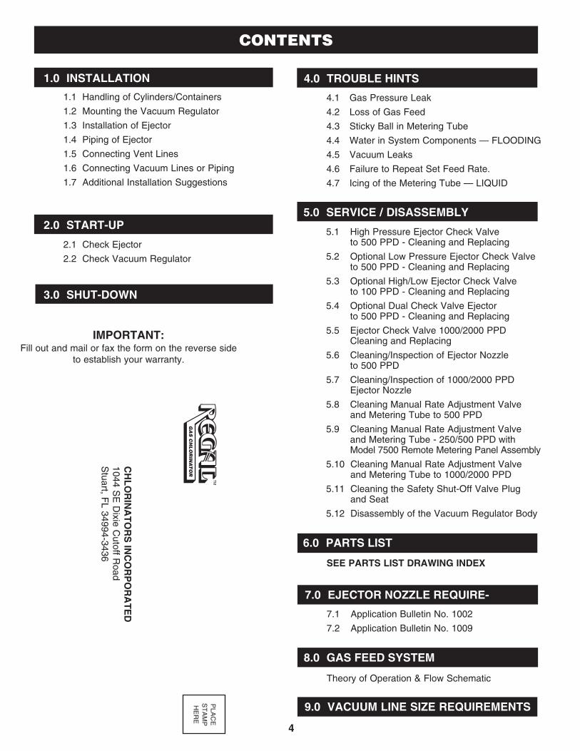
2.0 START-UP
1.1 Handling of Cylinders/Containers
1.2 Mounting the Vacuum Regulator
1.3 Installation of Ejector
1.4 Piping of Ejector
1.5 Connecting Vent Lines
1.6 Connecting Vacuum Lines or Piping
1.7 Additional Installation Suggestions
CONTENTS
2.1 Check Ejector
2.2 Check Vacuum Regulator
1.0 INSTALLATION
3.0 SHUT-DOWN
PLACE
STAMP
HERE
CHLORINATORS INCORPORATED
1044 SE Dixie C
utoff Road
Stuart, F
L 34994-3436
4
4.1 Gas Pressure Leak
4.2 Loss of Gas Feed
4.3 Sticky Ball in Metering Tube
4.4 Water in System Components — FLOODING
4.5 Vacuum Leaks
4.6 Failure to Repeat Set Feed Rate.
4.7 Icing of the Metering Tube — LIQUID
5.1 High Pressure Ejector Check Valveto 500 PPD - Cleaning and Replacing
5.2 Optional Low Pressure Ejector Check Valve to 500 PPD - Cleaning and Replacing
5.3 Optional High/Low Ejector Check Valve to 100 PPD - Cleaning and Replacing
5.4 Optional Dual Check Valve Ejector to 500 PPD - Cleaning and Replacing
5.5 Ejector Check Valve 1000/2000 PPD Cleaning and Replacing
5.6 Cleaning/Inspection of Ejector Nozzleto 500 PPD
5.7 Cleaning/Inspection of 1000/2000 PPD Ejector Nozzle
5.8 Cleaning Manual Rate Adjustment Valve and Metering Tube to 500 PPD
5.9 Cleaning Manual Rate Adjustment Valve and Metering Tube - 250/500 PPD with Model 7500 Remote Metering Panel Assembly
5.10 Cleaning Manual Rate Adjustment Valve and Metering Tube to 1000/2000 PPD
5.11 Cleaning the Safety Shut-Off Valve Plug and Seat
5.12 Disassembly of the Vacuum Regulator Body
SEE PARTS LIST DRAWING INDEX
4.0 TROUBLE HINTS
5.0 SERVICE / DISASSEMBLY
6.0 PARTS LIST
7.1 Application Bulletin No. 1002
7.2 Application Bulletin No. 1009
Theory of Operation & Flow Schematic
7.0 EJECTOR NOZZLE REQUIRE-
8.0 GAS FEED SYSTEM
9.0 VACUUM LINE SIZE REQUIREMENTS
PARTS LIST DRAWING INDEX SECTION 6.0
5
Drawing No. A-820 Chlorinator Parts List to 100 PPD (2000 Gm./Hr.)
Drawing No. A-822 Chlorinator Parts List @ 250 PPD (5000 Gm./Hr.)
Drawing No. A-825 Chlorinator Parts List @ 500 PPD (10Kg./Hr.)
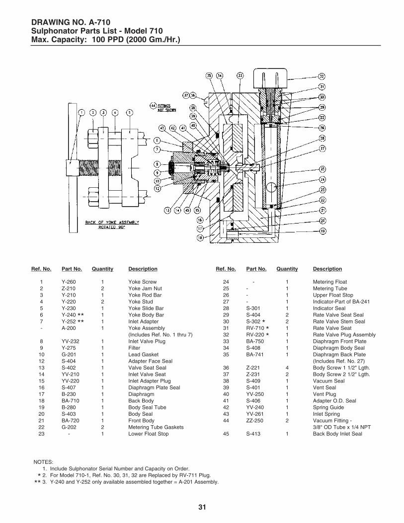
Drawing No. A-710 Sulphonator Parts List to 100 PPD (2000 Gm./Hr.)
Drawing No. A-720 Sulphonator Parts List @ 250 PPD (5000 Gm./Hr.)
Drawing No. A-750 Sulphonator Parts List @ 500 PPD (10 Kg./Hr.)
Drawing No. A-823 Ammoniator Parts List to 100 PPD (2000 Gm./Hr.)
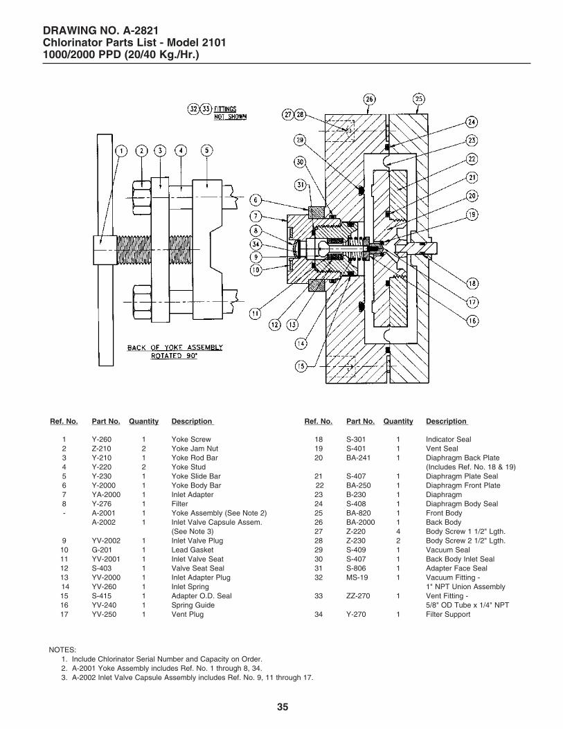
Drawing No. A-2821 Chlorinator Parts List @ 1000/2000 PPD (20/40 Kg./Hr.)
Drawing No. A-920/A-922/A-925 Chlorine Service Ejector Assembly (High Pressure)E-225/E-227/E-525 Chlorine Service Check Valve Assembly (High Pressure)
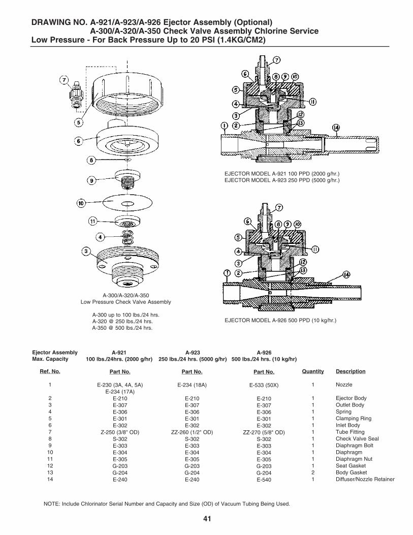
Drawing No. A-921/A-923/A-926 Chlorine Service Ejector Assembly (Low Pressure)A-300/A-320/A-350 Chlorine Service Check Valve Assembly (Low Pressure)
Drawing No. A-930/A-305 Chlorine Service Ejector Assembly (High/Low Pressure)
Drawing No. A-950/A-949 Chlorine Service Ejector/Dual Check Valve Assembly to 500 PPD (10 Kg./Hr.)
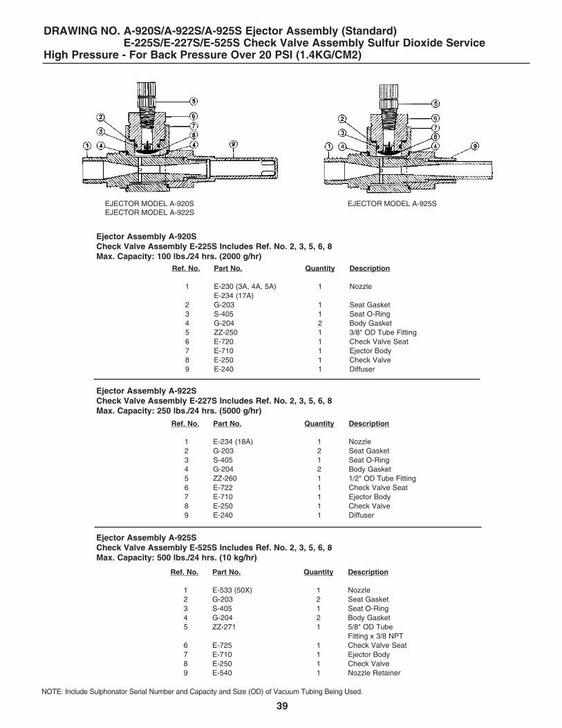
Drawing No. A-920S/A-922S/A-925S Sulfur Dioxide Service Ejector Assembly (High Pressure)E-225S/E-227S/E-525S Sulfur Dioxide Service Check Valve Assembly (High Pressure)
Drawing No. A-921S/A-923S/A-926S Sulfur Dioxide Service Ejector Assembly (Low Pressure)A-300S/A-320S/A-350S Sulfur Dioxide Service Check Valve Assembly (Low Pressure)
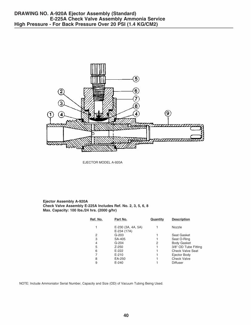
Drawing No. A-920A Ammonia Service Ejector Assembly (High Pressure)A-225A Ammonia Service Check Valve Assembly (High Pressure)
Drawing No. A-921A Ammonia Service Ejector Assembly (Low Pressure)A-300A Ammonia Service Check Valve Assembly (Low Pressure)
Drawing No. A-2920/A-2922 Chlorine Service Ejector Assembly @ 1000/2000 PPDA-2000 Chlorine Service Check Valve Assembly @ 1000/2000 PPD
Drawing No. A-2000 1000/2000 PPD Check Valve Parts List
Drawing No. A-255/A-255S/A-255A Remote Meter Panel Parts List to 100 PPD
Drawing No. A-7500 Remote Meter Panel Assembly 10 to 500 PPD
Drawing No. A-2551/A-2552 Remote Meter Panel Parts List @ 1000/2000 PPD
Data Sheet No. 2005 Vacuum Regulator Dimensions
Data Sheet No. 2006 Ejector Dimensions
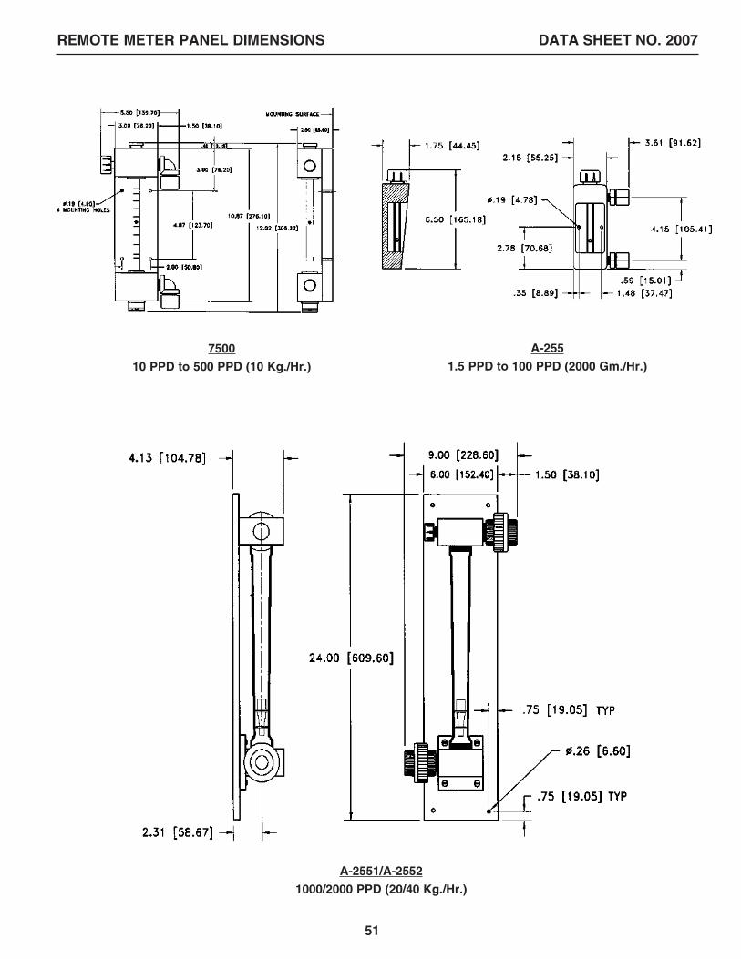
Data Sheet No. 2007 Remote Meter Panel Dimensions
6
IMPORTANTBefore proceeding, read the “IMPORTANT NOTESAND WARNINGS” in front of this manual.
REGAL Gas Feed Systems are vacuum operated solutionfeed types designed for mounting directly to the cylindervalve of a 150 lb. cylinder or, to the top valve of a one toncontainer using a REGAL TAY-200 ton container adapterassembly or, to the valve of an approved gas manifold.
The vacuum regulator mounts to the valve by means ofa positive, heavy duty yoke clamp and is sealed againstleakage by a lead gasket.
The vacuum regulator has a built-in spring opposeddiaphragm regulator and safety shut-off valve to maintainthe proper operating vacuum levels in the system. Gasfeed rate is manually adjusted.
A highly efficient water powered, vacuum producingejector is close coupled with the solution diffuser insystems to 500 PPD. Above 500 PPD, the solutiondiffuser is by others. All REGAL ejectors contain a backflow check valve.
The REGAL Gas Feed System incorporates the very bestavailable materials using the latest technology in designand construction. More than two dozen improvementshave been made to reduce maintenance, simplifyconstruction, and improve operation.
Each system consists basically of standard system componentsplus necessary water supply piping, parts, and extra accessoriesthat may be desired. The standard system package includes:
1. The vacuum regulator with built-in vent.
2. The ejector assembly with back flow check valve, nozzle,and diffuser (when supplied).
3. The remote metering panel assembly with manual rateadjustment valve (ONLY ON SYSTEMS REQUIRINGREMOTE METERING PANEL ASSEMBLIES).
4. Standard accessories and spare parts.
1.1 HANDLING OF CYLINDERS/CONTAINERSChlorine, Sulfur Dioxide, and Ammonia gas is potentiallydangerous. The following rules must always be adhered to:
1.1.1 Never move a cylinder/container unless the valveprotection domes and/or hoods are in place.
1.1.2 Locate the cylinder/container where they will notbe bumped or damaged.
1.1.3 A safety chain should be placed around cylindersand secured to a wall or support. Ton containersshould be secured in position using trunnions orother similar devices.
1.1.4 As a rule of thumb, chlorine and ammonia cylindersand/or containers should be stored and used inan environment of 50° F minimum. Sulfur dioxidecylinders and/or containers should be stored andused in an environment of 70° F minimum.
1.2 MOUNTING THE VACUUM REGULATOR
1.2.1 Remove the valve protection hood from the cylindersor the ton container.
1.2.2 If a ton container, rotate the container until the twooutlet valves are aligned vertically. This allows gasto be withdrawn from the top valve and liquid fromthe bottom valve. CONNECT TO THE TOP VALVEFOR GAS USE.
1.2.3 Unscrew the cap nut covering the valve outlet.
1.2.4 Remove any dirt that may be in the valve outlet oron the gasket sealing surfaces.
1.2.5 Remove all shipping tape from the vacuumregulator’s inlet. DO NOT REMOVE the filter thatis inserted in the vacuum regulator’s inlet.
1.2.6 If the vacuum regulator is cylinder mounted, unscrewthe yoke screw until the sliding bar can be pushedall the way back. Place a new 1/16˝ thick leadgasket over the vacuum regulator’s inlet. NEVERREUSE A GASKET. Use a new one every time theregulator is removed from a cylinder.
Mount the vacuum regulator on the cylinder valveby:
a. placing the yoke over the valve,
b. engaging the vacuum regulator inlet properlywith the valve outlet, and
c. carefully tightening the yoke clamping screw,using the integral tightening handle to compressthe lead gasket. Excessive tightening can squeezethe lead gasket out of the joint and cause a leakand/or damage to the equipment. (Photo 1.1)
1.2.7 If container mounted, mount the vacuum regulatorto the valve of a REGAL TAY-200 Ton ContainerAdapter Assembly by following the steps outlinedin 1.2.6 above.
a. Unscrew the yoke screw of the TAY-200adapter until the sliding bar can be pushed allthe way back.
b. Place a NEW lead gasket over the inlet adapterof the TAY-200 and mount the TAY-200 withregulator installed to the top container valveBEING CAREFUL TO ALIGN THE REGULATORSINLET PROPERLY TO THE VALVES OUTLET.If not aligned properly, the inlet adapter WILLBE DAMAGED.
c. Carefully tighten the yoke clamping screw of theTAY-200, using the integral tightening handle tocompress the lead gasket. Excessive tighteningcan squeeze the lead gasket out of the joint andcause a leak and/or damage to the equipment.
GENERAL
1.0 INSTALLATION (See Drawing 1, 2 or 3)
1.1
1.3 1.4
1.2
EJECTOR BODY
DIFFUSER
DIFFUSER
GASKET
GASKET
NOZZLE
GASKET
1.5
7
Drawing 1Typical installation of basic Model 210 type system.
8
Drawing 2Typical installation of a Multi-Point feed system. Ejectors installed as in Drawing 1.
Drawing 3Typical installation of a High Capacity Model 2100 system @ 1000/2000 PPD.
9
1.2.8 If manifold mounted, mount the vacuum regulatorto the appropriate valve of the manifold by followingthe steps outlined in 1.2.6 above. (Photo 1.8).
a. Using NEW lead gaskets and approved flexibleconnection lines, auxiliary container valves, etc.,connect each flexible connection line, auxiliarycontainer valve, etc. from each cylinder or TOPcontainer valve to the remaining manifold valves.
1.3 INSTALLATION OF EJECTOR1.3.1 The check valve in the ejector is designed so that
the ejector may be installed in any position. Thecheck valve assembly, components, and pipingMUST be supported to prevent breakage due towater hammer, vibration, etc. A horizontal mountingof the ejector is preferred. BE SURE THE PROPERCHECK VALVE IS USED TO MATCH THE SYSTEMAPPLICATION PRESSURE.
1.3.2 The point of injection should be carefully chosenso that the water pressure is as low as possible.Vacuum is created in the ejector by the nozzle -actually a precision designed venturi - so waterpressure to the nozzle must be high enough toovercome the total back pressure and create astrong jet in the nozzle.
1.3.3 Ejectors to 500 PPD are designed to withstandstatic back pressures up to 200 psig (14.1 kg/cm2).However, due to possibilities of water line “hammer”in high pressure on-off systems, as well as specialbooster pump considerations, it is recommendedthat a factory representative, or ChlorinatorsIncorporated be consulted regarding installationdetails in systems over 100 psig (7 kg/cm2).
Ejectors of 1000/2000 PPD are designed to withstandstatic back pressures up to 70 psig (4.9 kg/cm2).However, due to possibilities of water line “hammer”in high pressure on-off systems, as well as specialbooster pump considerations, it is recommendedthat a factory representative, or ChlorinatorsIncorporated be consulted regarding installationdetails in systems over 50 psig (3.5 kg/cm2).
1.3.4 Generally, the amount of water (GPM) required tooperate the ejector depends on the gas feed rate(lb/24 hrs, gms/hr, or kg/hr). The higher the gasfeed rate, the greater the water flow needed.Refer to Application Bulletins 1002 or 1009 inSection 7.0 of this manual.
1.3.5 Ejector water supply pressure must be greaterthan the pressure into which the gas solution isinjected. The amount of pressure differential mayvary with the particular application. Generally, thegreater the pressure into which the gas solutionwill be injected, the greater must the differentialpressure be. However, the minimum pressuredifferential and water flow for your installationshould be determined prior to installation andstart-up.
1.3.6 Follow these steps for installing ejectors up to 500PPD with close-coupled diffusers.
a. Unscrew the diffuser from the assembly. DONOT install the diffuser when assembled asdamage may occur.
b. Put teflon tape on the 3/4˝ pipe threads andscrew the diffuser into the pipe. These are highimpact plastic parts but, as with all plastic pipefittings, care should be exercised in tightening.Tighten carefully with a properly adjustedwrench. Make sure that the holes in the spraydiffuser are in the main stream.
The end of an open end diffuser should notallow the strong solution to come in contactwith any metal pipe or fittings as serious corrosionwill occur (See Photo 1.5).
c. Place a G-204 gasket into position on both thenozzle and the diffuser. Insert the nozzlethrough the check valve body (Photo 1.3) andscrew into the diffuser until contact is made withboth G-204 gaskets. Hold the check valve bodyagainst the diffuser at 1/8 turn COUNTER-CLOCKWISE from its final position (See Photo1.4). At the same time, turn both the nozzle andthe check valve body 1/8 turn clockwise to theirfinal tightened position. The check valve may beinstalled in any position - up, down, or sideways.
NOTE: A short length of hose is recommended between theejector and rigid piping to absorb vibrations.
1.3.7 Follow these steps for installing ejectors of1000/2000 PPD capacities. (See Drawing 3).
a. The nozzle (water inlet) and throat (solutionoutlet) connections are 2˝ NPT for use withcustomer furnished fittings, flanges, unions, etc.
b. The ejector’s gas inlet is a 1˝ NPT PVC union.
c. Use teflon tape on all threaded connections.Tighten threaded connections carefully, usingproperly sized wrenches, being careful not toover tighten, as damage to the parts couldresult. MAKE SURE ALL RIGID PIPE RUNSARE PROPERLY SUPPORTED.
1.3.8 Other types of diffuser and ejector installationsmay be desired for certain applications.
a. The ejector can be located near the other gasfeed system components when required. A wallbracket can be provided for ejectors to 500PPD. Various size adapters can be used on thesolution outlet to accommodate hose or pipe.
b. If the ejector is to be remotely installed withsolution piping or hose running to the point ofapplication, BE CERTAIN TO CUT OFF THETIP OF THE STANDARD DIFFUSER BEFOREINSTALLING INTO THE PIPE OR HOSE.Failure to do this will result in excessive backpressure being created in the diffuser, prevent-ing proper gas feed.
10
1.7
1.8
1.6
1˝ UNION
11
WARNING: The 500 PPD ejector nozzle (50X) extends beyondthe ejector body and the end of the E-540 nozzle retainer.DO NOT cut off the end of the nozzle.
c. The entire ejector assembly may be submergedin an open channel or tank.
d. Corporation cock type diffusers, ball valves,etc., can be used as required if properly sized.
1.4 PIPING OF EJECTOR (See Drawing 1 or 3)1.4.1 For most installations, the ejector water supply line
should be brought to within 3-5 feet of the nozzlewith rigid PVC or iron pipe. A 1000/2000 PPDejector will be directly connected to rigid PVCpipe on both sides.
1.4.2 A shut-off valve followed by a Y-strainer and theejector is recommended to enable servicing whennecessary.
1.4.3 A pressure gauge between the Y-strainer and theejector is recommended.
1.4.4 For 500 PPD and below ejectors, connect a shortlength of hose between the end of the rigidincoming water line and the ejector nozzle. Clampthe hose securely at both ends with single ordouble hose clamps (Photo 1.5).
1.5 CONNECTING VENT LINES1.5.1 Every REGAL gas feed system incorporates a
“vent” to allow pressurized gas an avenue ofescape when necessary. Venting occurs whendirt or impurities enter the vacuum regulator inletvalve plug and seat area, preventing a bubbletight closure of the valve plug.
1.5.2 Appropriate size flexible tubing is used for all ventconnections. Use enough length to allow movementof the vacuum regulators when necessary.
1.5.3 Route the tubing to a safe location outside thebuilding. The end of the vent line should pointdown to prevent rain water from entering, andshould be screened to keep insects from gettingin and building nests.
1.6 CONNECTING VACUUM LINES OR PIPING1.6.1 On 500 PPD and below systems, flexible vacuum
tubing is used to connect the various system components (Drawing #1 or #2).
a. Remove connector nuts from vacuum connectionsand slip onto tubing. Using appropriate lengthsof tubing, push onto connectors and tightenconnector nuts HAND TIGHT.
1.6.2 On 1000/2000 PPD systems 1˝ minimum Sch. 80PVC pipe and fittings are used to connect thevarious system components (See Drawing No. 3).
NOTE: 1. When 500 PPD and below systems are supplied with a
remote metering panel assembly or assemblies, the rateadjustment valve is removed from the vacuum regulatorand replaced with a non-adjustable plug. The meteringtube normally furnished in the vacuum regulator isreplaced with a plain glass tube without a float.
2. The metering panel assembly, which includes the meteringtube and the manual rate adjustment valve, is designedfor wall mounting using appropriate fasteners.
1.6.3 Each additional point of application (all capacities)consists of an additional metering panel assemblywith manual rate adjustment valve, and an additionalejector assembly. On capacities of 500 PPD andbelow, each additional feed point includes a lengthof flexible vacuum tubing and a tubing connectortee fitting (See Drawing No. 2).
1.7 ADDITIONAL INSTALLATION SUGGESTIONS1.7.1 Many operators find it convenient to install a hook
on the wall behind the cylinders or alongside thecontainers. When changing cylinders/containers, thevacuum regulator can easily be hung on this hook.
1.7.2 An appropriate scale should be used to weigh thecontents of the cylinders/containers to determinethe amount of chemical remaining.
2.1 CHECK EJECTOR (See Photo 1.5 or 1.7)2.1.1 The ejector assembly is the heart of the gas feed
system. It creates the vacuum necessary tooperate the remaining system components.Unless the ejector is creating a vacuum, the systemWILL NOT WORK. To check ejector operation:
a. Remove the vacuum tubing from the ejectortubing connector or unscrew the 1˝ PVC unionat the ejector vacuum connection.
b. With the booster pump running or the pressurizedwater supply connected, open the ejectorwater line supply valve and any other valvesthat may exist between the ejector outlet andthe point of chemical application. The ejectorshould now be in operation and creating astrong vacuum.
c. Check for proper operation by placing yourfinger or hand over the vacuum connectionopening. If there is no vacuum, refer to Section7.0 and be certain there is enough supplypressure and the nozzle or piping is not plugged.Proper vacuum must exist before proceeding.
2.0 START-UP
d. Shut off the water supply to the ejector andmake sure no water comes out of the vacuumconnection opening. If water is observed leakingpast the check valve, see Section 4.4 and correctbefore proceeding. Once the problem is corrected,cycle the ejector on and off a few times to makesure the check valve is tightly sealed. Waterleaks at this point CANNOT be tolerated.
e. Repeat this procedure for all ejectors present.
f. Reconnect the vacuum tubing or piping andleave the ejector running. On 1000/2000 PPDejectors, make sure the o-ring is not lost fromthe union connection.
2.2 CHECK VACUUM REGULATOR(See Photo 1.1 or 1.6)2.2.1 With the ejector operating and the gas cylinder(s)/
container(s) still closed, the ball or float in the meteringtube will remain at the bottom. If it does not, or if itbounces up and down, there is either a leak at thelead gasket where the vacuum regulator connects tothe cylinder/container/manifold valve, or a looseconnection in the system. Check and correct.
2.2.2 The supply indicator on the face of the vacuumregulator should be below the surface of theregulator body, indicating an “out of gas” condition.
2.2.3 Turn the rate valve on the vacuum regulator (or onthe remote metering panel assembly) counter-clockwise a few turns, to be sure the float remainsat the bottom of the metering tube.
2.2.4 Close the ejector water supply valve to stopoperation of the ejector.
2.2.5 Disconnect the flexible vacuum tubing (or disconnectthe 1˝ vacuum union) at the vacuum regulator to allowair to enter the system. Reconnect the vacuum line.
2.2.6 Open and immediately close the gas valve of thecylinder/container.
2.2.7 Chlorine and sulfur dioxide leaks are best locatedusing a dauber moistened with commercial 26 degreeBaume’ aqueous ammonia (household ammoniais not strong enough). A white cloud will form at thesite of any leak. A plastic squeeze bottle which directsammonia vapors, NOT LIQUID, at the joint beingtested may also be used.
Ammonia leaks are best located using moist litmuspaper which turns color on exposure to ammoniafumes or by using sulfur dioxide or strong chlorinebleach fumes which both form a heavy whitesmoke when mixed with ammonia vapors.
NOTE: If a pressure manifold system is being used, beginchecking for leaks at the furthest cylinder/container connection.Check small sections of the manifold at a time until the entiremanifold is found to be leak tight.
When a leak is detected the system must be depressurizedbefore corrective action is taken.
NOTE: If the REGAL Vacuum Regulator is mounted on a toncontainer using a REGAL TAY-200 Ton Container AdapterAssembly, OPEN the valve on the TAY-200 Assembly 1/4 - 1/2turn and repeat steps 2.2.6 and 2.2.7.
2.2.8 If no leaks were detected, open the gas cylinder/ container/manifold valve(s) 1/4 turn, leave openand recheck for leaks one more time.
2.2.9 Turn on the water supply to the ejector(s) andadjust the gas feed rate to the desired setting.
NOTE: NEVER use the rate valve to shut off the gas supply.This valve is for adjusting the gas feed rate only. To shut off thegas supply, close the cylinder/container/manifold valve(s).
3.1 Shut off the gas cylinder/container valvesleaving all other gas pressure valves open.
a. The ejector should be running. The “out of gas”indicator pin should be recessed below thesurface of the vacuum regulator.
WARNING: Even if the gas feed rate drops to zero as evidencedby the position of the ball or float in the metering tube and/or arecessed status indicator pin, and even if the supply containerappears to be empty, SOME LIQUID CHEMICAL MAY STILL BEPRESENT.
NEVER disconnect the vacuum regulator from the cylinder/container/manifold valve until ALL cylinder/container/manifoldvalves are FULLY CLOSED or a highly dangerous chemicalleak causing severe injuries or death could occur.
3.2 Shut off the water line supply valve orbooster pump to the ejector.
3.3 When changing the gas cylinders/containers,follow the procedure on the cylinder/containerchanging chart supplied with your REGALgas feed system.
3.0 SHUT-DOWN
12
13
This section covers all phases of service on REGAL Gas FeedSystems. Normally it is not necessary to completely disassemblethe systems components unless it is to be cleaned throughout,or has been severely flooded. DO NOT DISASSEMBLE THE UNITS MERELY FOR THE SAKE OF DISASSEMBLY.
All units have been factory tested and are in A1 condition whenthey are shipped. This text describes some of the things thatcan cause a REGAL gas feed system to stop working. Read itcarefully and find out what the problem is, before attempting tocorrect it.
REGAL Gas Feed Systems will require minimum service if operatedwith reasonable care. Problems which could arise are listedbelow.
IMPORTANT: BEFORE PROCEEDING, READ THE “PRECAUTIONSFOR PERSONAL AND SYSTEM PROTECTION” AT THEFRONT OF THIS MANUAL.
4.1 GAS PRESSURE LEAKThere are four possible points of gas pressure leaks. These arerare, but if a gas leak is detected, it should be immediatelylocated and stopped. Even small leaks can create a safetyhazard and cause serious corrosion to equipment in the area.
4.1.1 Cylinder/container/manifold valve packing.
The cylinder/container/manifold valves are highquality valves designed specifically for the gasservice intended. Chemical suppliers should servicethese valves at each filling, and leakage at thispoint is unusual. Should a leak develop, tightenthe valve packing nut without exerting excessiveforce. If this does not eliminate the leak, close thevalve and call the chemical supplier.
4.1.2 The lead gasket seal between the vacuumregulators and the cylinder/container/manifold valves.
A leak at this point could be caused by reusing alead gasket, by dirt on the gasket surfaces,under or over tight connections, or by installationwithout a gasket, or the use of a “fiber” typegasket instead of lead. ALWAYS USE A NEWLEAD GASKET. Make certain the gasket andgasket surfaces are clean and smooth. Tightenclamps, but not excessively.
4.1.3. Safety shut off inlet valve plug and seat – VENTING(Photo 5.14 & 5.15).
Gas leaking out of the vent is an indication of aleak at the inlet valve plug and seat. The usualcause is dirt on the valve seat. Test to make certainthe problem is a leak at this point.
a. Shut off water supply to ejector assembly.
b. Submerge the end of the vent tubing in a glassof water. Continuous bubbling is an indicationof a gas leak.
c. Before removing the unit from the cylinder/container/manifold, close the cylinder/container/manifold valve, turn on the watersupply, and allow the vacuum regulator tooperate until the metering ball or float drops tothe bottom (ZERO).
NOTE: A gas leak around the S-404 and S-406 o-rings couldalso result in a vent leak.
4.1.4 Vacuum regulator adapter face seal S-404. Gasleaking out between the back body and the yokeassembly usually indicates a leak at the o-ring sealbetween the inlet valve capsule and the inlet adapter.The usual causes are listed below. See Section 5.12.
a. Improper tightening of the inlet valve capsuleafter disassembly.
b. Dirt or impurities on the o-ring or sealingsurfaces.
c. A leak around the S-404 and S-413 o-ringscould result in a gas leak between the yokebody bar and the back body.
4.2 LOSS OF GAS FEED4.2.1 No vacuum. This can readily be checked by removing
the gas line at the ejector vacuum inlet and holdingyour finger or hand over the opening. Suitablevacuum will exert a strong pull. If there is no vacuum,the ejector nozzle may be plugged. Refer toSection 5.6 or 5.7.
4.2.2 Insufficient water pressure to operate the ejector.This can be readily checked as in 4.2.1 above.
4.2.3 No gas supply. This should be obvious. When the gassupply becomes empty, the metering ball or floatwill not indicate above zero gas feed rate, and thesupply indicator pin will be below the vacuumregulator face.
4.2.4 Plugged inlet filter. Dirt from the cylinder/containermay completely plug the high efficiency, porousfilter. The filter may be removed for inspection andcleaning. See Section 5.11, “Cleaning Safety Shut-OffValve and Seat.”
4.2.5 Poor air circulation around the cylinder/containerresulting in low cylinder/container pressure andpossible frost build-up.
4.0 TROUBLESHOOTING HINTS
GENERAL
Care and Maintenance of yourREGAL Gas Feed System
4.3 STICKY BALL IN METER TUBE4.3.1 Deposits
a. The gas may contain traces of organiccompounds which deposit on the ball or float orthe inside of the glass tube. This deposit isoften sticky, causing the ball or float to adhereto the surface of the glass, resulting in erraticoperation. When this occurs, it is necessary toremove the flow meter tube assembly from theunit for cleaning. The cleaning procedure isoutlined in Section 5.8, 5.9 or 5.10.
b. The frequency of cleaning depends on anumber of factors – notably the quality of thechemical and the operating temperature of theinstallation.
4.3.2 Moisture in the system.
a. In the normal course of operation, moistureshould not be present. However, it is possiblewhen changing cylinders or containers, thatvery moist air could be drawn into the inletor the vacuum regulators. This can causethe metering ball or float to become “sticky”particularly at the bottom (small end) of the tube.
b. If the vacuum regulator has been previously“flooded” (See Section 4.4) it is possible that allmoisture has not been removed from all gaspassageways in the system.
c. A severe vacuum leak can allow moist air toenter the system (See Section 4.4).
4.4 WATER IN SYSTEM COMPONENTS -“FLOODING”4.4.1 During normal operation, vacuum is drawing gas
through the system and water cannot enter. When thesystem is shut down and vacuum is lost, water isprevented from backing up by the check valve in theejector assembly. Any water observed in the meteringtube or any other system component indicates afailure of the check valve. If the check valve has failed:
a. Close the cylinder/container/manifold valve thevacuum regulator is attached to.
b. Shut off the water supply to the ejector and thewater in the main, so there is no pressure in theejector piping.
c. Remove the vacuum tubing or piping from theejector and follow instructions for “Cleaning andReplacing the Ejector Check Valve,” Section5.1, 5.2, 5.3, 5.4 or 5.5.
d. Remove the vacuum regulator from thecylinder/container/manifold valve. Carefullyfollow instructions in Section 5.12 to be sureall moisture is removed from ALL systemcomponents prior to reassemble and start-up.
e. If the system is using a remote metering panelassembly, remove the metering tube and followinstructions in Section 5.8, 5.9 or 5.10“Cleaning Metering Tube.”
4.5 VACUUM LEAKS4.5.1 For best operation, all parts of the system should
be airtight, since vacuum leaks will permit air toenter. All units are vacuum tested at the factoryprior to shipment, so a vacuum leak in a new unitis unlikely. Furthermore, it is very unusual for leaksto develop during operation unless the unit hasbeen disassembled or physically damaged.
4.5.2 A simple test determines whether the system isfree of vacuum leaks:
a. Operate the system at an arbitrary gas feed setting.
b. Shut off the cylinder/container/manifold valvethat the vacuum regulator is attached to. IT ISASSUMED THAT IT WILL SHUT TIGHTLY. Adefective valve will give erroneous results.
c. The float or ball in the metering tube should dropto zero. This may take a minute or two dependingupon capacity. If the ball or float does not drop tothe bottom, this indicates a vacuum leak at somepoint in the system, usually between the vacuumregulator inlet and the metering tube.
d. When the ball or float drops to zero, shut off theejector water supply. Note that the indicator pinin the center of the vacuum regulator body isrecessed below the surface of the body, indicatingan “out of gas” condition. With a perfectly tightsystem, this condition will remain. Usually a 5 to10 minute check is all that is needed. If a leakexists in the system, the diaphragm assemblywill move forward causing the indicator pin toreset with the tip protruding slightly.
4.5.3 The most common cause of vacuum leaks isimproper assembly of the system componentsafter they have been taken apart for servicing.
4.5.4 The most common points of leakage are:
a. Gas metering tube seals (o-rings or gaskets).Check to make sure the meter tube o-rings orgaskets are in good condition and properlyinstalled. Metering tube gaskets can be reused,but they should be turned over.
b. Rate valve o-rings. Rate valve o-rings maybecome worn. Fouling of the surfaces mightcause abrasion of the o-ring surface. Checkand replace as necessary.
c. Sealing surface at main diaphragm. Animperfection or a speck of dirt on this surfaceduring reassembly may cause a leak, butREGAL’s unique use of a compression sealingo-ring makes this unlikely.
d. Vacuum connections. Check all vacuum tubingand piping for leaks and cracks. On 1000/2000PPD systems, make sure all union o-rings arein place.
e. Other possible, but less common points of leakage:
1. O-ring in connecting passage of bodies.
2. O-ring at inlet capsule.
3. Vent seal on diaphragm plate.
4. Back body inlet seal.
5. Diaphragm plate seal.
14
15
4.6 FAILURE TO REPEAT SET FEED RATE4.6.1 On start-up, a system with a dirty meter tube or rate
adjustment valve may not repeat. This is particularlytrue of low capacity systems of 10 PPD or less.Correction of this situation can be accomplished by:
a. Cleaning the rate adjustment valve as outlinedin Section 5.8, 5.9 or 5.10.
b. Cleaning the metering tube as outlined inSection 5.8, 5.9 or 5.10. The frequency ofcleaning depends on the quality of the gaschemical being used.
4.6.2 Failure to repeat may also occur if any of the systemcomponents have been flooded and moistureremains in the metering and rate adjustment area.
4.7 ICING OF THE METERING TUBE—LIQUID4.7.1 If ice is observed forming on the metering tube
assembly, it is a definite indication that LIQUIDchemical has entered the vacuum regulator fromthe source of supply. While this is extremely rare,our experience has shown that suppliers havebeen known to overfill cylinders/containers fromtime to time. Also, if the cylinders are tipped overwhile the vacuum regulator is attached and operating,liquid could be drawn into the system.
If manifold assemblies are being used, make surethe manifold contains a suitable liquid trap (drip leg)with an appropriate (WORKING) heater installed.
4.7.2 If the system has been subjected to liquid chemical,do the following:
IMPORTANT: Before proceeding, read the “Precautions forPersonal and System Protection” at the front of this manual.
a. Shut off the cylinder/container/manifold valves.
b. Leave the ejector running and developing avacuum in the system.
c. Remove the vacuum regulator from thecylinder/container/manifold valve.
d. Quickly remove the vacuum tubing from thevacuum regulator and observe that the supplyindicator is above the surface.
e. Reconnect the vacuum tubing or piping andopen the rate adjustment valve to maximum.The system will now draw air into the vacuumregulator inlet, vaporizing any remaining liquid.Allow the system to draw air for several minutes.
f. Shut off the ejector.
g. Either OUTDOORS OR IN A WELL VENTILATEDROOM, follow instructions in Section 5.12, titled“Disassembly of vacuum regulator body.” Cleanall parts with denatured alcohol, and replace anyparts that show signs of liquid chemical attack.
h. Reassemble and follow start-up procedure inSection 2.0.
PREVENTIVE MAINTENANCE SCHEDULE REGAL SYSTEMS AND SYSTEM COMPONENTS
The best, most cost effective, and easiest way to assure thatyour gas feed system and equipment will provide continuous,dependable, trouble free operation, is to establish a PREVENTIVEMAINTENANCE SCHEDULE. This will assure minimumunscheduled down time. The maintenance schedule should bein writing and include as a minimum, the date of installation, thescheduled date of maintenance, the actual date the maintenancewas performed, the parts used, and any applicable notes.
All REGAL products are engineered for easy maintenance andthis manual provides step by step procedures to properly serviceand maintain each component within the system. It is your (thecustomer’s) responsibility to establish and undertake aSCHEDULED MAINTENANCE PROGRAM.
To support this program, we have available a variety of“REPAIR KITS” containing the parts we feel you may need forminor emergency repairs. We recommend that these kits beavailable in your stock at all times. When this kit, or any partsare used, the kit should be replaced immediately. This manualcontains complete parts lists for each system component. Assuch, you can order and stock additional parts as deemednecessary.
AT A MINIMUM, THIS EQUIPMENT SHOULD RECEIVESCHEDULED MAINTENANCE AT LEAST ONCE A YEAR.Depending on the installation, application, location ofcomponents, quality of gas, etc., this equipment may needscheduled maintenance more than once a year. This issomething that needs to be determined on a job by job basis.
Spare parts and/or repair kits may be ordered directly from thecompany who supplied your equipment, or they may beordered directly from our inventory in Stuart, Florida.
IMPORTANT: Maintenance on REGAL Systems or SystemComponents should be performed by competent personnelfamiliar with this type of equipment such as authorized REGALDealers or Chlorinators Incorporated themselves.
WARNING: Even if the gas feed rate drops to zero asevidenced by the position of the ball or float in the meteringtube and/or the supply indicator pin is below the surface of thehead, and even if the supply container appears empty, SOMELIQUID CHEMICAL MAY STILL BE PRESENT.
NEVER disconnect the vacuum regulator from the cylinder/container/manifold valve until ALL cylinder/container/manifoldvalves are FULLY CLOSED or a highly dangerous chemicalleak causing sever injuries or death could occur.
5.0 SERVICE/DISASSEMBLY
16
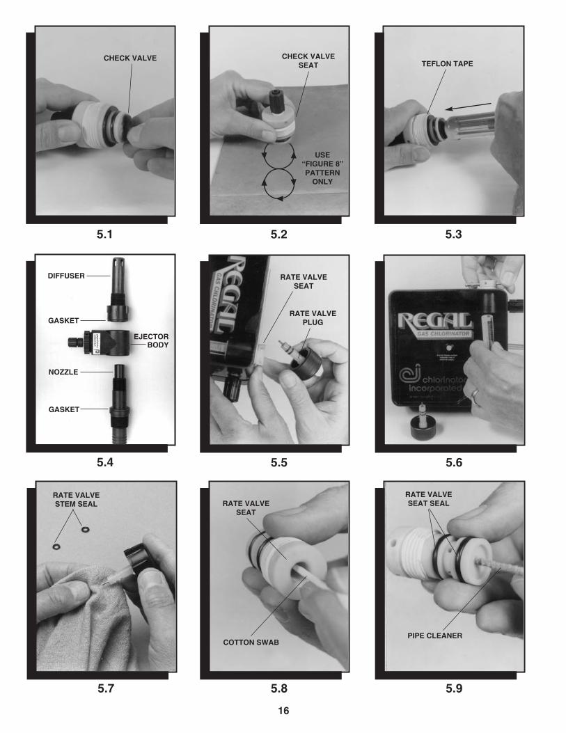
5.1
5.5
5.35.2
5.7
5.6
5.8 5.9
CHECK VALVE CHECK VALVE SEAT TEFLON TAPE
RATE VALVESEAT
RATE VALVESEAT
COTTON SWABPIPE CLEANER
RATE VALVESEAT SEAL
RATE VALVEPLUG
USE “FIGURE 8”PATTERNONLY
5.4
DIFFUSER
GASKET
GASKET
EJECTORBODY
NOZZLE
RATE VALVESTEM SEAL
17
5.1 HIGH PRESSURE EJECTOR CHECK VALVETO 500 PPD - CLEANING AND REPLACING(See appropriate Parts Drawing A-920/A-922/A-925, A-920S/A-922S/A-925S or A-920A)
5.1.1 A check valve is installed in the ejector assemblyto prevent water from backing into the system whenthe ejector is shut off. The check valve design issuch that it is extremely difficult for dirt to get underthe valve, but it might, if large amounts of sand orother impurities are present in the water supply;and dirt could possibly enter from the gas side. Toremove and clean the valve, proceed as follows:
a. Close the cylinder/container/manifold valve(s)before working on any system component.
b. Shut off the water supply to the ejector and thewater pressure in the main.
c. Remove vacuum tubing from the fitting on topof the ejector assembly.
d. Unscrew the check valve seat from theejector body using pliers if necessary.
e. Carefully lift the edge of the check valve(Photo 5.1) and inspect.
f. If the check valve and seat are in good condition,clean both the valve and the seating surface andreinstall the check valve seat into the ejectorbody. Use a thin film of Vaseline or Dow CorningDC33 on the seat o-ring and seat gasketas necessary. DO NOT USE ANY OTHERPETROLEUM BASED GREASES OR OILS.
g. Make sure the check valve seat is screwedcompletely into the ejector body. USE NOTOOLS. HAND TIGHTEN ONLY.
h. Pressurize the ejector and cycle several timesbefore reconnecting the vacuum tubing tomake sure the check valve is sealing properly.
i. If wear or damage is noted, the check valvemust be replaced. If the check valve needs tobe replaced, proceed as follows:
1) Grasp the outer edges of the check valveand apply a steady pulling force until the“umbrella” shaped stem “pops” free. Becertain it is completely removed.
2) Examine the check valve seat sealingsurface for deposits, and clean withdenatured alcohol.
3) Check the seat sealing surface with astraight edge to be certain it is completelyflat. If the center is slightly raised, you willsee light under the straight edge, or it will“rock” over the center. If the seat sealingsurface is not flat, use a very fine sandpaperor emery cloth on a flat surface (e.g., plateglass) and gently move the check valveseat in a figure 8 pattern (Photo 5.2). Do notrub back and forth, or the seat will becomedistorted.
4) Wet the tip of the new check valve with avery light film (make shiny only) of Vaselineor Dow Corning DC33. Put the tip of thecheck valve in the “center” check valveseat hole and, using the handle of a screw-driver or other rounded object, push againstthe center of the check valve until the tipsnaps into the seat (Photo 5.3). DO NOTTWIST THE CHECK VALVE OR DAMAGEMAY OCCUR.
j. When reinstalling the check valve seat, put athin film of Vaseline or Dow Corning DC33 onthe seat o-ring and seat gasket for lubrication.DO NOT USE ANY OTHER PETROLEUMBASED GREASES OR OILS.
k. Screw the check valve seat clockwise into theejector body. Use no tools. Hand tighten only.
l. Pressurize the ejector and cycle several timesbefore reconnecting the vacuum tubing toensure that the check valve is sealing properly.
5.2 OPTIONAL LOW PRESSURE EJECTOR CHECK VALVE TO 500 PPD -CLEANING AND REPLACING(See appropriate Parts Drawing A-921/A-923/A-926,A-921S/A-923S/A-926S or A-921A)
5.2.1 To remove and clean the check valve, proceed asfollows:
a. Close the cylinder/container/manifold valve(s)before working on any system component.
b. Shut off the water supply to the ejector and thewater pressure in the main.
c. Remove the vacuum tubing from the fitting ontop of the ejector assembly.
d. Unscrew (counterclockwise) the entire checkvalve assembly out of the ejector body.Make sure the seat gasket remains in placeand is in good condition. Replace if necessary.
e. Using a “spanner” wrench in the holes locatedin the underside of the outlet body, unscrewthe outlet body from the clamping ring. Do notlose the spring or the diaphragm assembly.
1) The diaphragm is made from a specialcorrosion resistant plastic. Inspect it carefullyfor nicks or cuts. Replace as necessary.
2) The check valve action is accomplished bythe diaphragm bolt sealing tightly on theo-ring located in the center of the inletbody when the ejector is shut off. As such,the diaphragm bolt sealing surface and theo-ring must be free of dirt or impurities thatmay prevent an effective seal. Clean orreplace as necessary.
f. Reassemble by reversing steps “a” through “d”above.
18
5.10
5.13 5.14
5.125.11
5.16
5.15
5.17
YOKEASSEMBLY
ADAPTERFACE SEAL
INLETADAPTER
INLET ADAPTERPLUG
VENT PLUG
SPRING GUIDE
INLET SPRING
INLETADAPTERPLUG
INLET VALVE PLUG
INLETVALVEPLUG
VENTPLUG
INLET VALVE SEAT
Y-275 INSTALLATION
TYP. SECTION OFCHLORINATOR ORSULPHONATOR
RECOMMENDEDFILTERINSTALLATION
5.18
1/ 32˝ (.81 mm)SPACING
19
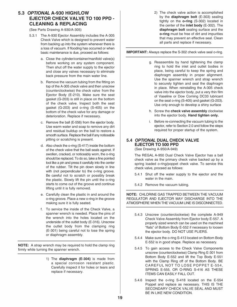
5.3 OPTIONAL A-930 HIGH/LOW EJECTOR CHECK VALVE TO 100 PPD - CLEANING & REPLACING (See Parts Drawing A-930/A-305)
5.3.1 The A-930 Ejector Assembly includes the A-305Check Valve which is designed to prevent waterfrom backing up into the system whenever there isa loss of vacuum. If flooding has occurred or whenbasic maintenance is due, proceed as follows:
a. Close the cylinder/container/manifold valve(s)before working on any system component.Then shut off the water supply to the ejectorand close any valves necessary to eliminateback pressure from the main water line.
b. Remove the vacuum tubing from the fitting ontop of the A-305 check valve and then unscrew(counterclockwise) the check valve from theEjector Body (E-210). Make sure the seatgasket (G-203) is still in place on the bottomof the check valve. Inspect both the seatgasket (G-203) and o-ring (S-405) on thebottom of the check valve for any damage ordeterioration. Replace if necessary.
c. Remove the ball (E-556) from the ejector body.Use warm water and soap to remove any dirtand residual buildup on the ball to restore asmooth surface. Replace the ball if any noticeablepitting or scratching is present.
d. Also check the o-ring (S-417) inside the bottomof the check valve that the ball seals against. Ifswollen, cracked, or noticeably worn, the o-ringshould be replaced. To do so, take a fine pointedtool like a pin and press it carefully into the centerof the rubber. Tilt the pin down slowly in linewith (not perpendicular to) the o-ring groove.Be careful not to scratch or possibly breakthe plastic. Slowly lift the pin until the o-ringstarts to come out of the groove and continuelifting until it is fully removed.
e. Carefully clean the plastic in and around theo-ring groove. Place a new o-ring in the groovemaking sure it is fully seated.
f. To service the inside of the Check Valve, aspanner wrench is needed. Place the pins ofthe wrench into the holes located on theunderside of the outlet body (E-316). Unscrewthe outlet body from the clamping ring(E-301) being careful not to lose the springor diaphragm assembly.
NOTE: A strap wrench may be required to hold the clamp ringfirmly while turning the spanner wrench.
1) The diaphragm (E-304) is made froma special corrosion resistant plastic.Carefully inspect it for holes or tears andreplace if necessary.
2) The check valve action is accomplishedby the diaphragm bolt (E-303) sealingtightly on the o-ring (S-302) located inthe center of the inlet body (E-302). Thediaphragm bolt sealing surface and theo-ring must be free of dirt and impuritiesthat may prevent an effective seal. Cleanall parts and replace if necessary.
IMPORTANT: Always replace the S-302 check valve seal o-ring.
g. Reassemble by hand tightening the clampring to hold the inlet and outlet bodies inplace, being careful to keep the spring anddiaphragm assembly in proper alignment.Use the spanner wrench and strap wrenchto securely tighten and seal the diaphragmin place. When reinstalling the A-305 checkvalve into the ejector body, put a very thin filmof Vaseline or Dow Corning DC33 lubricanton the seat o-ring (S-405) and gasket (G-203).Use only enough to develop a shiny surface
h. Screw the check valve assembly clockwiseinto the ejector body. Hand tighten only.
i. Before re-connecting the vacuum tubing to theejector, refer to Section 2.0 and follow the stepsrequired for proper startup of the system.
The REGAL A-950 Dual Check Valve Ejector has a ballcheck valve as the primary check valve backed up by aspring loaded o-ring/poppet check valve. To service thischeck valve, proceed as follows:
5.4.1 Shut off the water supply to the ejector and thewater in the main.
5.4.2 Remove the vacuum tubing.
NOTE: CHLORINE GAS TRAPPED BETWEEN THE VACUUMREGULATOR AND EJECTOR MAY DISCHARGE INTO THEATMOSPHERE WHEN THE VACUUM LINE IS DISCONNECTED.
5.4.3 Unscrew (counterclockwise) the complete A-949Check Valve Assembly from Ejector body E-557. Aproperly sized wrench can be used on the machined“flats” of Bottom Body E-552 if necessary to loosenthe ejector body. DO NOT USE PLIERS.
5.4.4 Make sure the o-ring S-413 located on Bottom BodyE-552 is in good shape. Replace as necessary.
5.4.5 To gain access to the Check Valve Componentsunscrew (counterclockwise) Clamp Ring E-301 fromBottom Body E-552 and lift the Top Body E-551with the Clamp Ring off of the Bottom Body. BECAREFUL NOT TO LOSE POPPET E-554,SPRING E-555, OR O-RING S-416 AS THESEITEMS CAN EASILY FALL OUT.
5.4.6 Inspect the o-ring S-418 located on the E-554Poppet and replace as necessary. THIS IS THESECONDARY CHECK VALVE SEAL AND MUSTBE IN LIKE NEW CONDITION.
20
5.19
5.22 5.23
5.215.20
5.25
5.24
5.26 5.27
ADAPTER OD SEAL
BACKBODYINLETSEAL
DIAPHRAGMASSEMBLY FRONT DIAPHRAGM PLATE
ALIGNBODY SEAL TUBE OPENINGS
LEAVE APPROX.1/16˝ (1.6mm)GAP
DIAPHRAGM BODY SEAL
BODYSEAL
BODYSEALTUBE
BACK DIAPHRAGM PLATE
DIAPHRAGM
FRONTBODY
BACKBODY
21
5.4.7 Inspect and clean as necessary the flat surfaceinside Top Body E-551. Since this is the sealingsurface for the S-418 sealing o-ring. THIS SURFACEMUST BE CLEAN AND PERFECTLY FLAT.
5.4.8 The primary check valve is located inside BottomBody E-552. To gain access to the primary checkvalve, proceed as follows:
a. Using Drawing A-950/A-949 as a guide, carefullyunscrew (counterclockwise) the Spring/BallRetainer E-553 from Bottom Body E-552. THEOUTER CIRCUMFERENCE OF THESPRING/BALL RETAINER IS KNURLED TOMAKE IT EASIER TO UNSCREW.
ONCE REMOVED, THE BALL E-556 IS FREETO FALL OUT. BE CAREFUL NOT TO LOSEOR DAMAGE THE BALL.
b. Inspect the Ball E-556 and make sure it is free ofall deposits, nicks, and pits. If in doubt, replaceas necessary.
c. Poppet E-553 contains two o-rings. The S-415o-ring is a sealing o-ring and MUST remain in itsgroove when reassembling the check valvecomponents. Inspect this o-ring for wear andreplace as necessary.
d. The second o-ring S-417 is a critical o-ring as itis the sealing surface for the primary checkdevice (Ball E-556). This o-ring is located in anundercut groove at the base of Spring/BallRetainer E-553.
If o-ring S-417 shows any signs of wear or, ifo-ring S-417 is flattened due to the check actionof Ball E-556, replace with a new one.
5.4.9 Clean all check valve parts with warm water and/ora mild solvent such as denatured alcohol.
5.4.10 Make sure all parts are thoroughly dry and allo-rings are in place and reassemble by reversingthe steps outlined in Section 5.4.
5.5 EJECTOR CHECK VALVE 1000/2000 PPD -CLEANING OR REPLACING (Refer to Drawing A-2920/2922)
5.5.1 A-2000 CHECK VALVEA check valve is installed in the ejector assemblyto prevent water from backing into the systemwhen the ejector is shut off. The check valvedesign is such that it is extremely difficult for dirt tolodge under the valve, but it might, if largeamounts of sand or other impurities are present inthe water supply; and dirt could possibly enterfrom the chemical side. To remove and clean thevalve, proceed as follows:
a. Close the manifold valve that the vacuumregulator is attached to before working on anysystem components.
b. Shut off the water supply to the ejector and thewater pressure in the main.
c. Open the 1˝ PVC vacuum union MS-19 byunscrewing (counterclockwise) the union ringand move the vacuum piping out of the way. Becareful not to lose the vacuum union o-ring.
NOTE: CHLORINE GAS TRAPPED BETWEEN THE VACUUMREGULATOR AND EJECTOR MAY DISCHARGE INTO THEATMOSPHERE WHEN THE VACUUM LINE IS DISCONNECTED.
d. Using Parts List Drawing A-2000 as a guide,unscrew Clamp Ring CV-2004 and lift the TopBody CV-2002 with Clamp Ring off BottomBody CV-2001 and set aside. BE SURE NOTTO LOSE O-RING S-804.
e. Carefully lift out Poppet CV-2003 and SpringCV-2005.
f. Poppet CV-2003 contains an o-ring S-805which is the check valve seal. THIS O-RINGMUST BE IN PERFECT SHAPE, FREE OFNICKS, CUTS, ETC. IF NECESSARY,REPLACE IT WITH A NEW ONE.
IF O-RING S-805 SHOWS SIGNS OF BEINGFLATTENED DUE TO THE ACTION OF THENEW CHECK VALVE, REPLACE IT WITH ANEW ONE.
g. Inspect the flat surface inside Top BodyCV-2002 to be sure it is flat and clean. THISIS THE SURFACE O-RING S-805 SEALSAGAINST.
h. Clean all check valve parts with warm water ora mild solvent such as denatured alcohol anddry thoroughly.
i. Reassemble the ejector check valve assemblyby reversing steps “a” through “e.”
5.6 CLEANING/INSPECTION OF EJECTOR NOZZLE TO 500 PPD5.6.1 To remove the ejector nozzle for cleaning, the
water pressure in the main must first be shut offunless the ejector was initially installed with a valveon the inlet side and a ball valve or corporation stopin the outlet, so that isolation of the ejector is possible.
a. Close the cylinder/container/manifold valve(s)before working on any system component.
5.6.2 Remove the ejector supply hose and gas vacuumtubing from the ejector assembly.
5.6.3 Rotate the complete ejector body counterclockwise,making certain that the solution diffuser remainsfixed in the solution piping or main (Photo 1.3).
5.6.4 Unscrew the nozzle from the ejector body. Checkthe gaskets located in each side of the body andreplace if necessary (Photo 1.3).
5.6.5 Nozzle plugging can be caused by:
a. A piece of foreign material (pipe sealer, stone,or dirt) lodging in the nozzle orifice. This canusually be blown out in the reverse direction.DO NOT USE SHARP TOOLS OR ALTERTHE SIZE OF THE ORIFICE IN ANY WAY.
b. Excess plastic pipe solvent or glue used duringinitial installation running into the orifice area ofthe nozzle. If this cannot be cleaned out easily,the nozzle may need to be replaced.
22
5.29 5.30 5.31
5.32
5.28
23
c. Build-up of deposit. This could be a chemicalbuild-up of iron, manganese, or some othermaterial which usually can be removed byimmersing the nozzle in muriatic acid andrinsing. CAUTION: READ ALL WARNING LABELSON THE MURIATIC ACID CONTAINER, ANDAVOID SKIN CONTACT. It is recommendedthat safety goggles or face shield be used whenworking with any strong acid. Some waters aresuch that build-up of deposits can cause anejector to become inoperative in a short periodof time.
5.6.6 To reinstall the nozzle:
a. Insert the nozzle through the ejector body andscrew into the solution diffuser. Make sure thegaskets are in place and in good condition(Photo 1.3).
b. Hold the ejector body against the diffuser at1/8 turn counterclockwise from its final position(Photo 1.4).
c. Screw the nozzle into the diffuser by handuntil contact is made against both gaskets.
d. Turn the ejector body and the nozzle at thesame time, 1/8 turn clockwise to the final tightposition (Photo 1.4). THE PARTS ARE PLASTIC,AND EXCESSIVE TIGHTENING MAY CAUSEBREAKAGE. DO NOT USE TOOLS.
e. Reinstall the ejector supply hose and vacuumtubing (Photo 1.5).
5.6.7 Open all valves and check for proper operatingvacuum.
5.7 CLEANING/INSPECTION OF 1000/2000 PPD EJECTOR NOZZLE5.7.1 The ejector nozzle and throat thread into the
ejector body. To inspect and clean these parts,proceed as follows:
a. Close the manifold valve that the vacuumregulator is attached to before working on anysystem components.
b. Shut off the water supply pressure to the ejector,and close any valves in the chlorine solution lineso as to isolate the ejector assembly.
c. Open the 1˝ PVC vacuum union MS-19 byunscrewing (counterclockwise) the union ringand move the vacuum piping out of the way.
NOTE: CHLORINE GAS TRAPPED BETWEEN THE VACUUMREGULATOR AND EJECTOR MAY DISCHARGE INTO THEATMOSPHERE WHEN THE VACUUM LINE IS DISCONNECTED.
Be careful not to lose the vacuum union o-ring.
d. Open or disconnect the 2˝ unions, flanges,fittings, etc., holding the ejector assembly intothe pipeline, and remove the ejector. WHENREMOVING AND/OR INSTALLING THECOMPLETE EJECTOR ASSEMBLY, BECAREFUL NOT TO LOOSEN OR OVER-TIGHTEN THE NOZZLE AND THROATWHICH COULD CAUSE DAMAGE TO THESEPARTS AND/OR WATER LEAKS.
e. Carefully clean or remove any foreign materialthat may have accumulated in the ejectornozzle or throat area, being careful not toscratch or mar the nozzle orifice.
NOTE: DO NOT USE SHARP TOOLS OR ALTER THE SIZEOF THE ORIFICE IN ANY WAY.
f. If chemical deposits have built up in the nozzleor throat area, immerse the part in muriaticacid. REMOVE ALL O-RINGS OR GASKETSFIRST.
IMPORTANT: READ ALL WARNING LABELS ON MURIATICACID CONTAINER AND FOLLOW ALL SAFETY INSTRUCTIONS.
g. Reassemble by reversing steps “a” through “e.”
5.8 CLEANING MANUAL RATE ADJUSTMENTVALVE AND METERING TUBE ON SYSTEMS TO 500 PPD (MODELS 210, 210-1, 220, 250, 720 AND 750 ONLY)
NOTE: Close the cylinder/container/manifold valve(s) beforeworking on any system component.
5.8.1 Unscrew and remove the rate valve plug assemblyfrom the top of the metering tube (Photo 5.5).
5.8.2 Insert the rate valve tool supplied with the gas feedsystem through the side holes in the top of the ratevalve seat. While holding the metering tube withone hand, turn the seat counterclockwise until freeof its threads. The metering tube can now beremoved (Photo 5.6).
5.8.3 Grasp the rate valve seat and pull up while turninguntil it pops out.
5.8.4 To clean the rate valve plug:
a. Clean the silver tip and the plug shaft withlacquer thinner or acetone (Photo 5.7). DONOT USE LACQUER THINNER OR ACETONEON O-RINGS OR ANY OF THE ABS PARTS.
b. Examine the o-rings and make sure they arefree of nicks and scratches. Clean them with amild solvent, such as denatured alcohol.Replace if necessary. Use a light film ofVaseline or Dow Corning DC33 on the o-ringsand rate valve plug threads.
5.8.5 To clean the rate valve seat:
a. Use a cotton swab with a small amount ofdenatured alcohol to clean out the inside of therate valve seat (Photo 5.8).
b. If dirt or deposits have formed in the meteringorifice of the rate valve seat, a pipe cleanerdipped in denatured alcohol can be carefullyinserted through the orifice and gently movedback and forth (Photo 5.9). Do not use lacquerthinner or acetone.
c. Clean the metering tube gasket surfaces withthe alcohol soaked cotton swab.
d. Inspect and clean the rate valve seat o-ringswith denatured alcohol. Replace if necessary.
5.8.6 To clean the metering tube:
a. Bend a paper clip or small wire, and pull out thefloat stops on each end of the glass meteringtube (Photo 5.10). MAKE SURE YOU DON’TLOSE THE METERING BALL.
b. Clean the glass tube with a pipe cleaner usingdenatured alcohol, and rinse. DO NOT USELACQUER THINNER OR ACETONE AS THESECHEMICALS WILL REMOVE THE NUMBEREDSCALE ON THE TUBE’S EXTERIOR.
c. Reinstall ball float and float stops.
5.8.7 Place teflon tape on threads of the rate valveseat, and apply a thin film of Vaseline or DowCorning DC33 to the o-rings. Install the ratevalve seat into the metering panel housing usinga clockwise rotation until the threads engage.
5.8.8 Reinstall the metering tube as follows:
a. The metering tube gaskets can usually bereused by turning them over. If damaged,replace them. Place one gasket on the ratevalve seat, and one gasket on the recess ofthe meter panel assembly at the bottom of themetering tube area.
b. Center the top of the metering tube under therate valve seat and center the bottom over thehole in the lower gasket.
c. Using the rate valve tool, tighten (clockwise)the rate valve seat while holding the meteringtube in place with the numbers of the properscale facing front. Be sure the tube is centeredover the gasket holes.
d. When the metering tube no longer can beeasily rotated, tighten the rate valve seatanother 1/4 to 1/2 turn. Do not over tighten.
5.8.9 Replace the rate valve plug assembly by placingit into the top of the rate valve seat and gentlypushing down while rotating, until the o-rings popsinto the seat and the threads can engage. Tightendown the rate valve a few turns.
5.9 CLEANING MANUAL RATE ADJUSTMENTVALVE AND METERING TUBE @ 250/500 PPD (MODELS 220-1, 250-1, 720-1 AND 750-1 ONLY)(Refer to Drawing A-7500)
NOTE: The REGAL Model 7500 Remote Meter PanelAssembly is furnished with the 250 PPD and 500 PPD REGALsystems noted above. It is an OPTION on REGAL systems @10 PPD to 100 PPD.
Servicing of the #7500 remote metering panel assemblywill generally be limited to cleaning of the glass rotametertube and ball float which sometimes stick due to impuritieswithin the chemical itself, and cleaning and/or replacementof the rate valve plug o-rings. To clean the rotameter tubeassembly:
5.9.1 Using the chemical feed systems rate valve tool (or anail), unscrew meter tube plug (#7505) counterclock-wise one or more turns while holding the glass metertube assembly (#7501-See Chart) with your other handto protect the tube from damage due to dropping, etc.
5.9.2 Carefully lift the glass metering tube assembly out ofthe remote metering panel housing. MAKE SUREYOU DON'T LOSE OR DAMAGE THE METERINGBALL FLOAT. Set the tube and float in a safe place.Also, make sure the top and bottom bushings andgaskets are not lost or damaged.
5.9.3 Bend a paper clip or small wire, and pull out the floatstops on each end of the glass metering tube.
5.9.4 Clean the glass tube inside and out using denaturedalcohol (or warm water) and rinse with clear water anddry thoroughly.
CAUTION: DO NOT use lacquer thinner, acetone or otherharsh solvents as these chemicals WILL remove the numberedscale on the exterior of the tube.
5.9.5 Clean the ball float with denatured alcohol (orwarm water), rinse and dry thoroughly.
5.9.6 Reassemble the tube, float and float stops. MAKESURE THE FLOAT NO LONGER STICKS INSIDETHE TUBE. REPEAT STEPS 5.9.3 THROUGH 5.9.6AS NECESSARY.
CAUTION: Before unscrewing meter tube plug (#7505),unscrew the tube fitting from bottom block (#7503). While slowlyunscrewing the meter tube plug, look into the fitting openingand using a small screwdriver, carefully push on the o-ring toprevent shearing on the inlet hole.
24
5.9.7 Unscrew meter tube plug (#7505) until it is free ofits mating threads. Continue turning the plugcounterclockwise while pulling down until the plugpops out of the bottom block (#7503).
5.9.8 If necessary, clean the plug with alcohol or warmwater, rinse thoroughly and dry.
5.9.9 If the two (2) meter tube plug o-rings (S-406) showsigns of wear, replace them with new ones. Use alight film of Vaseline or Dow Corning DC33 siliconegrease on the o-rings.
5.9.10 The meter tube gaskets and top and bottom bushinggaskets (See chart for proper part numbers) canusually be reused by turning them over. If theyappear to be damaged, replace them.
5.9.11 Unscrew rate valve plug assembly (#RV-831) byturning counterclockwise until it pops free. Clean theplug assembly and top block (#7504) as necessary.
5.9.12 Replace rate valve plug o-rings (S-403) asnecessary. Apply a light film of Vaseline or DowCorning DC33 Silicone grease to the o-rings andthe rate valve plug threads.
5.9.13 Screw meter tube plug (#7505) into bottom block(#7503) until the threads engage with those of thebottom block.
CAUTION: While slowly screwing the meter tube plug into thebottom block, look into the fitting opening and using a smallscrewdriver, carefully push on the o-ring to prevent shearing onthe inlet hole.
5.9.14 Place the top and bottom bushing gaskets (Seechart for proper part numbers) in their respectiverecesses in the top and bottom blocks of theRemote Meter Panel Assembly.
5.9.15 Set the bottom bushing and the bottom meter tubegasket (See chart for proper part numbers) on topof the bottom bushing gasket.
5.9.16 Carefully place the top meter tube gasket and thetop bushing (See chart for proper part numbers)on the top of the meter tube assembly and placethe assembly into position in the Remote MeterPanel Assembly.
5.9.17 Using the rate valve tool (or a nail), tighten (clockwise)the meter tube plug until the meter tube assemblyis snug and can no longer be rotated with yourfingers. DO NOT OVERTIGHTEN.
5.9.18 Replace the rate valve plug assembly into the topblock by gently pushing down while rotating, untilthe o-rings pop into the seat area and the threadscan engage. Tighten down the rate valve a few turns.
5.9.19 Replace the tube fitting into the bottom block(#7503).
5.10 CLEANING MANUAL RATE ADJUSTMENT VALVE AND METERING TUBE - 1000/2000 PPD(Refer to Drawing A-2551/A2552)
5.10.1 To clean the rate adjustment valve, proceed as follows:
a. Close the manifold valve that the vacuumregulator is attached to before working on anysystem components.
b. Unscrew the rate valve plug assembly fromthe rate valve seat.
c. Clean or replace the two rate valve stem seals(Photo 5.28) as necessary. The shaft of the ratevalve can be cleaned with warm soapy water,denatured alcohol, or lacquer thinner as needed.
IMPORTANT: Remove the two stem seals before using lacquerthinner. The two seals can be cleaned with denatured alcohol.
d. Examine the two seals and make sure theyare free of nicks and scratches. Replace ifnecessary.
e. Use a light film of Vaseline or Dow CorningDC33 on the o-rings and threads.
f. If dirt or deposit have formed in the meteringorifice of the rate valve seat, a cloth dipped indenatured alcohol can be carefully insertedthrough the orifice and gently moved back andforth (Photo 5.29).
g. Reinsert the rate valve plug assembly witho-rings installed into the rate valve seat usingfirm pressure and a continual clockwise rotationof the plug assembly until the threads engage.The clockwise rotation prevents the o-ringsfrom being damaged.
NOTE: Do not simply press the rate valve plug assembly intothe seat as this will damage the o-rings.
5.10.2 To clean the metering tube, proceed as follows:
a. Unscrew or open the 1˝ NPT PVC vacuuminlet union at the flow meter inlet block. Donot lose the union o-ring.
b. Remove the four mounting screws from thebase plate while holding the metering tubesecurely in one hand (Photo 5.30 & 5.31).
c. Carefully remove the flow meter inlet blockand the metering tube assembly from theback panel and place them on a paddedsurface, being careful not to lose or damagethe metering tube float.
d. Clean the glass tube and the metering tubefloat with a soft cloth using denatured alcohol(Photo 5.32). DO NOT USE LACQUER THINNEROR ACETONE, AS THESE CHEMICALS WILLREMOVE THE NUMBER SCALE ON THETUBE EXTERIOR.
25
e. Rinse all parts in warm water, and drythoroughly before reassembling.
f. Clean top and bottom metering tube o-ringswith denatured alcohol or warm soapy water.Dry thoroughly.
g. Inspect, clean, or replace top and bottommetering tube o-rings as necessary.
h. Reassemble metering tube assembly byreversing this procedure.
5.11 CLEANING THE SAFETY SHUT-OFF VALVE PLUG AND SEATThe need for cleaning the safety shut-off inlet valve plug andseat is usually caused by a “VENTING” condition. Ventingoccurs when dirt or impurities enter the vacuum regulatorinlet valve plug and seat area, thereby preventing a bubbletight closure of the valve plug. To disassemble, proceed asfollows:
IMPORTANT: CLOSE THE CYLINDER/CONTAINER/MANIFOLD VALVE(S) BEFORE WORKING ON ANY SYS-TEM COMPONENT AND REMOVE THE VACUUM REGULA-TOR FROM THE CYLINDER/CONTAINER/MANIFOLD.
5.11.1 Remove the two screws holding the yoke bodybar to the vacuum regulator body.
5.11.2 Pull the entire yoke assembly from the vacuumregulator body using a clockwise rotation. It shouldslip out relatively easily (Photo 5.11).
5.11.3 To disassemble the inlet capsule:
a. Turn the inlet adapter plug counterclockwise.If the plug is tight use pliers, but be careful notto damage the adapter plug o-rings. The endof the valve plug is now exposed (Photo 5.12).
b. Insert a screwdriver into the slot in the end ofthe valve plug and unscrew the bullet-shapedvent plug. This can often be unscrewed byhand (Photo 5.13). If pliers are necessary,make sure the rounded seat surface of the ventplug is not scratched.
c. Remove the inlet valve plug, inlet spring, andinlet spring guide (Photo 5.14).
d. Inspect the sealing surface of the inlet valveseat. This surface must be completely free ofdirt, nicks, or scratches. A magnifying glassgives a good indication of the condition of theseat. Use a cotton swab dipped into lacquerthinner or denatured alcohol to carefully cleanthe seat. DO NOT attempt to clean the seatwith a sharp tool. Replace the valve seat if it isnot in perfect condition. Normally it will not benecessary to remove the valve seat from theinlet adapter plug unless it needs to bereplaced. To remove, use one of the vacuumregulator body bolts inserted through the inletspring side of the adapter plug. Place the headof the screw against a hard surface, and pushfirmly on the adapter until the valve seat popsfree (Photo 5.15).
e. Immerse the valve plug and vent plug inlacquer thinner or alcohol. Usually, a deposit ofcrystalline organic material, or a hard varnish-like material, will form along the valve stembelow the valve seating surface. Wipe thesurfaces clean with a clean cloth, and inspectthe tapered valve sealing surface and the roundedvent plug sealing surface. These surfaces mustbe completely free of dirt, nicks, and scratches.
f. Clean the inlet adapter before proceeding withassembly. A small tube or bottle brush withdenatured alcohol works well here. Remove andinspect the adapter face seal o-ring beforeapplying any cleaning agent to the adapter.
g. The adapter face seal o-ring and all otherparts may be cleaned with a cloth dipped indenatured alcohol.
h. The inlet filter may be removed for inspectionfor dirt build-up and cleaning, by pushing apencil eraser tip through the inlet adapter(Photo 5.16). Dirt and deposits can usually beremoved by immersing the filter in muriaticacid, and then thoroughly rinsing in clear water.READ ALL LABELS ON THE ACID CONTAINER.AVOID SKIN CONTACT. DO NOT BREATHEVAPORS. SAFETY GOGGLES OR FACESHIELD SHOULD BE WORN. Dry filterthoroughly with air hose or dryer.
5.11.4 To reassemble, proceed as follows:
a. Replace the filter in the inlet adapter, usingfinger pressure.
b. Replace the inlet valve seat and the valveseat o-ring, if they were removed from theadapter plug. A very light film of Vaseline orDow Corning DC33 should be put on the o-ring,and the seat then slowly pushed into theadapter plug.
c. Insert the inlet valve plug through the valveseat.
d. Place the inlet adapter plug with inlet valvestem facing up on a smooth clean surface andproceed.
e. Insert the inlet spring in the inlet adapterplug recess. Slip on the spring guide over theinlet plug and press down onto the spring sothat the lip of the guide snaps into the center ofthe spring coil.
f. Compress the spring guide and screw on thevent plug a few turns (Photo 5.17)
g. Place a screwdriver in the inlet valve plug slot,hold the vent plug with the other hand, andscrew down the vent plug until the springguide bottoms on the shoulder of the inletvalve plug. The spring should compress untilapproximately 1/32˝ (1mm) of clearance isobserved between the top to the adapter plugand the spring guide (Photo 5.18).
h. Check alignment of valve stem assembly. Itshould appear straight when viewed from anyangle.
26
i. Place the adapter face seal o-ring intothe groove in the inlet adapter.
j. Place a very light film of Vaseline or DowCorning DC33 on the threads of the inletadapter plug assembly, and screw into theyoke assembly clockwise. Use pliers andtighten until you are certain the plug isbottomed. The plastic used in this plug isvery strong; just be careful you do notdamage the adapter plug OD sealingo-ring (Photo 5.19).
k. Put a light film of Vaseline or Dow CorningDC33 on the adapter plug OD sealingo-ring and on the back body inlet seal(Photo 5.20).
l. Insert the entire yoke assembly into thevacuum regulator body, using a slightclockwise rotation. DO NOT TURN THEYOKE ASSEMBLY COUNTERCLOCKWISE;doing so may unscrew the inlet safetycapsule (Photo 5.11).
5.12 DISASSEMBLY OF THE VACUUMREGULATOR BODY5.12.1 Normally it is not necessary to completely
disassemble the vacuum regulators unless athorough cleaning is needed, or parts need tobe replaced. If disassembly is necessary, proceedas follows:
a. Remove the yoke assembly as described in5.11.1 and 5.11.2 above.
b. Remove the four screws that hold the bodyassembly together and separate the bodyhalves (Photo 5.21).
c. Grasp the diaphragm back plate and pull theentire diaphragm assembly out of the frontbody. If the indicator seal o-ring is sticking inthe front body, push on the end of the indicatorpin with your finger, while pulling thediaphragm from the front body (Photo 5.22).
d. Examine the diaphragm. It is normal for somewrinkles to be present. The diaphragm is madeof special, very tough, chlorine resistant material.Should it be necessary to disassemble thediaphragm, proceed as follows:
1. Grasp both the front and back diaphragmplates and unscrew them (Photo 5.23). Iftight, use a strap wrench and vise, beingcareful not to damage them.
2. The diaphragm can now be removed. Notethe position of the “convolution” on thediaphragm. The raised portion should alwaysface the back of the vacuum regulator.
e. Clean the parts thoroughly with denatured alcohol.
f. Carefully inspect all o-rings for damage orwear and replace them if necessary. All o-ringsshould receive a very thin film of Vaseline orDow Corning DC33.
NOTE: Excessive use of lubricants can cause additionalservice problems.
5.12.2 Reassemble the unit using the reverse procedure,and check the following:
a. Be certain the diaphragm plate seal o-ring isseated in its groove in the diaphragm backplate subassembly before reassembling thediaphragm components.
b. Be certain that the diaphragm body sealo-ring and the vacuum seal o-ring are properlyseated in their grooves in the back body. If indoubt, replace these o-rings.
c. Be certain that the diaphragm assemblymoves freely in the front body. Press it forwardseveral times, to be certain it returns to “neutral”position (Photo 5.25).
d. Place the back body on a table with the largediaphragm body seal o-ring in place, andlower the front body onto it (Photo 5.24)
e. Grasp the entire unit, and turn it over so thatthe back body is on top, and reassemble thefour 1 1/2˝ (38 mm) screws. These screwsshould be screwed in until they just begin totighten. Tighten lower left hand screw first.
5.12.3 Replace the yoke assembly, by reversing steps5.11.1 and 5.11.2. Use the two 2 1/2˝ long screws.
5.12.4 Tighten all screws in a criss-cross pattern untilthey are all snug. If you have access to a torquescrewdriver calibrated in inch-pounds, tighten allscrews to 20 in.-lb of torque. DO NOT OVERTIGHTEN.Sealing is accomplished by the diaphragm bodyseal o-ring between the bodies.
THERE SHOULD BE A GAP OF APPROXIMATELY 1/16˝(1.6MM) BETWEEN BODY HALVES. DO NOT ATTEMPT TOCLOSE THIS GAP BY TIGHTENING THE BODY SCREWS(PHOTO 5.27).
27
28
Ref. No. Part No. Quantity Description 1 Y-260 1 Yoke Screw 2 Z-210 2 Yoke Jam Nut 3 Y-210 1 Yoke Rod Bar 4 Y-220 2 Yoke Stud 5 Y-230 1 Yoke Slide Bar 6 Y-240 ** 1 Yoke Body Bar 7 Y-252 ** 1 Inlet Adapter - A-200 1 Yoke Assembly (Includes Ref. No. 1 thru 7) 8 YV-230 1 Inlet Valve Plug 9 Y-275 1 Filter 10 G-201 1 Lead Gasket 12 S-404 1 Adapter Face Seal 13 S-402 1 Valve Seat Seal 14 YV-210 1 Inlet Valve Seat 15 YV-220 1 Inlet Adapter Plug 16 S-407 1 Diaphragm Plate Seal 17 B-230 1 Diaphragm 18 BA-210 1 Back Body 19 B-280 1 Body Seal Tube 20 S-403 1 Body Seal 21 BA-220 1 Front Body 22 G-202 2 Metering Tube Gaskets 23 - 1 Lower Float Stop 24 - 1 Metering Float
Ref. No. Part No. Quantity Description
25 - 1 Metering Tube 26 - 1 Upper Float Stop - A-210 * 1 Metering Tube Assem. (Includes Ref. No. 22 Thru 26) 27 - 1 Indicator-Part of BA-241 28 S-301 1 Indicator Seal 29 S-404 2 Rate Valve Seat Seal 30 S-302 * 2 Rate Valve Stem Seal 31 RV-210 * 1 Rate Valve Seat 32 RV-220 * 1 Rate Valve Plug Assembly 33 BA-250 1 Diaphragm Front Plate 34 S-408 1 Diaphragm Body Seal 35 BA-241 1 Diaphragm Back Plate (Includes Ref. No. 27) 36 Z-220 4 Body Screw 1 1/2" Lgth. 37 Z-230 2 Body Screw 2 1/2" Lgth. 38 S-409 1 Vacuum Seal 39 S-401 1 Vent Seal 40 YV-250 1 Vent Plug 41 S-406 1 Adapter O.D. Seal 42 YV-240 1 Spring Guide 43 YV-260 1 Inlet Spring 44 Z-250 2 Vacuum Fitting- 3/8" OD Tube x 1/4 NPT 45 S-413 1 Back Body Inlet Seal
DRAWING NO. A-820Chlorinator Parts List - Model 210 Max. Capacity: 100 PPD (2000 Gm./Hr.)
NOTES: 1. Include Chlorinator Serial Number and Capacity on Order.
* 2. For Model 210-1, Ref. No. 30, 31, 32 are Replaced by RV-211 Plug, A-210 Metering Tube Assembly is Replaced by Z-260 Plain Glass Tube.
**3. Y-240 and Y-252 only available assembled together = A-201 Assembly.
29
Ref. No. Part No. Quantity Description
1 Y-260 1 Yoke Screw 2 Z-210 2 Yoke Jam Nut 3 Y-210 1 Yoke Rod Bar 4 Y-220 2 Yoke Stud 5 Y-230 1 Yoke Slide Bar 6 Y-240 ** 1 Yoke Body Bar 7 Y-252 ** 1 Inlet Adapter - A-200 1 Yoke Assembly (Includes Ref. No. 1 thru 7) 8 YV-230 1 Inlet Valve Plug 9 Y-275 1 Filter 10 G-201 1 Lead Gasket 12 S-404 1 Adapter Face Seal 13 S-402 1 Valve Seat Seal 14 YV-210 1 Inlet Valve Seat 15 YV-220 1 Inlet Adapter Plug 16 S-407 1 Diaphragm Plate Seal 17 B-230 1 Diaphragm 18 BA-210 1 Back Body 19 B-280 1 Body Seal Tube 20 S-403 1 Body Seal 21 BA-222 1 Front Body 22 G-202 2 Metering Tube Gaskets 23 - 1 Lower Float Stop 24 - 1 Metering Float
Ref. No. Part No. Quantity Description
25 - 1 Metering Tube 26 - 1 Upper Float Stop - A-220 * 1 Metering Tube Assem. (Includes Ref. No. 22 Thru 26) 27 - 1 Indicator-Part of Ref. No. 35 28 S-301 1 Indicator Seal 29 S-404 2 Rate Valve Seat Seal 30 S-302 * 2 Rate Valve Stem Seal 31 RV-212 * 1 Rate Valve Seat 32 RV-222 * 1 Rate Valve Plug Assembly 33 BA-250 1 Diaphragm Front Plate 34 S-408 1 Diaphragm Body Seal 35 BA-241 1 Diaphragm Back Plate (Includes Ref. No. 27) 36 Z-220 4 Body Screw 1 1/2" Lgth. 37 Z-230 2 Body Screw 2 1/2" Lgth. 38 S-409 1 Vacuum Seal 39 S-401 1 Vent Seal 40 YV-250 1 Vent Plug 41 S-406 1 Adapter O.D. Seal 42 YV-240 1 Spring Guide 43 YV-260 1 Inlet Spring 44 ZZ-260 2 Fitting - 1/2" OD Tube x 1/4 NPT 45 S-413 1 Back Body Inlet Seal
DRAWING NO. A-822Chlorinator Parts List - Model 220 250 PPD (5000 Gm./Hr.)
NOTES: 1. Include Chlorinator Serial Number and Capacity on Order. * 2. For Model 220-1, Ref. No. 30, 31, 32 are Replaced by RV-211 Plug,
A-220 Metering Tube Assembly is Replaced by Z-260 Plain Glass Tube.
** 3. Y-240 and Y-252 only available assembled together = A-201 Assembly.
Ref. No. Part No. Quantity Description
1 Y-260 1 Yoke Screw 2 Z-210 2 Yoke Jam Nut 3 Y-210 1 Yoke Rod Bar 4 Y-220 2 Yoke Stud 5 Y-230 1 Yoke Slide Bar 6 Y-240 ** 1 Yoke Body Bar 7 Y-252 ** 1 Inlet Adapter - A-200 1 Yoke Assembly (Includes Ref. No. 1 thru 7) - A-201 See Note 3 8 YV-230 1 Inlet Valve Plug 9 Y-276 1 Filter 10 G-201 1 Lead Gasket 12 S-404 1 Adapter Face Seal 13 S-402 1 Valve Seat Seal 14 YV-210 1 Inlet Valve Seat 15 YV-220 1 Inlet Adapter Plug 16 S-407 1 Diaphragm Plate Seal 17 B-230 1 Diaphragm 18 BA-210 1 Back Body 19 B-280 1 Body Seal Tube 20 S-403 1 Body Seal 21 BA-520 1 Front Body 22 G-502 1 Metering Tube Gasket (Upper) 22A G-503 1 Metering Tube Gasket (Lower) 23 - 1 Lower Float Stop 24 - 1 Metering Float
Ref. No. Part No. Quantity Description
25 - 1 Metering Tube 26 - 1 Upper Float Stop - A-510 * 1 Metering Tube Assem. (Includes Ref. No. 22 Thru 26) 27 - 1 Indicator-Part of BA-241 28 S-301 1 Indicator Seal 29 S-404 2 Rate Valve Seat Seal 30 S-302 * 2 Rate Valve Stem Seal 31 RV-512 * 1 Rate Valve Seat 32 RV-520 * 1 Rate Valve Plug Assembly 33 BA-250 1 Diaphragm Front Plate 34 S-408 1 Diaphragm Body Seal 35 BA-241 1 Diaphragm Back Plate (Includes Ref. No. 27) 36 Z-220 4 Body Screw 1 1/2" Lgth. 37 Z-230 2 Body Screw 2 1/2" Lgth. 38 S-409 1 Vacuum Seal 39 S-401 1 Vent Seal 40 YV-250 1 Vent Plug 41 S-406 1 Adapter O.D. Seal 42 YV-240 1 Spring Guide 43 YV-260 1 Inlet Spring 44 ZZ-271 1 Vacuum Fitting - 5/8" OD Tube x 3/8 NPT 44A ZZ-270 1 Vent Fitting - 5/8" OD Tube x 1/4 NPT 45 S-413 1 Back Body Inlet Seal 46 Y-270 1 Filter Support
DRAWING NO. A-825Chlorinator Parts List - Model 250 500 PPD (10 Kg./Hr.)
NOTES: 1. Include Chlorinator Serial Number and Capacity on Order. * 2. For Model 250-1, Ref. No. 30, 31, 32 are Replaced by RV-714 Plug,
A-510 Metering Tube Assembly is Replaced by A-511 Plain Glass Tube.
** 3. Y-240 and Y-252 only available assembled together = A-201 Assembly.
30
31
DRAWING NO. A-710Sulphonator Parts List - Model 710 Max. Capacity: 100 PPD (2000 Gm./Hr.)
NOTES: 1. Include Sulphonator Serial Number and Capacity on Order. * 2. For Model 710-1, Ref. No. 30, 31, 32 are Replaced by RV-711 Plug.** 3. Y-240 and Y-252 only available assembled together = A-201 Assembly.
Ref. No. Part No. Quantity Description
1 Y-260 1 Yoke Screw 2 Z-210 2 Yoke Jam Nut 3 Y-210 1 Yoke Rod Bar 4 Y-220 2 Yoke Stud 5 Y-230 1 Yoke Slide Bar 6 Y-240 ** 1 Yoke Body Bar 7 Y-252 ** 1 Inlet Adapter - A-200 1 Yoke Assembly (Includes Ref. No. 1 thru 7) 8 YV-232 1 Inlet Valve Plug 9 Y-275 1 Filter 10 G-201 1 Lead Gasket 12 S-404 1 Adapter Face Seal 13 S-402 1 Valve Seat Seal 14 YV-210 1 Inlet Valve Seat 15 YV-220 1 Inlet Adapter Plug 16 S-407 1 Diaphragm Plate Seal 17 B-230 1 Diaphragm 18 BA-710 1 Back Body 19 B-280 1 Body Seal Tube 20 S-403 1 Body Seal 21 BA-720 1 Front Body 22 G-202 2 Metering Tube Gaskets 23 - 1 Lower Float Stop
Ref. No. Part No. Quantity Description
24 - 1 Metering Float 25 - 1 Metering Tube 26 - 1 Upper Float Stop 27 - 1 Indicator-Part of BA-241 28 S-301 1 Indicator Seal 29 S-404 2 Rate Valve Seat Seal 30 S-302 * 2 Rate Valve Stem Seal 31 RV-710 * 1 Rate Valve Seat 32 RV-220 * 1 Rate Valve Plug Assembly 33 BA-750 1 Diaphragm Front Plate 34 S-408 1 Diaphragm Body Seal 35 BA-741 1 Diaphragm Back Plate (Includes Ref. No. 27) 36 Z-221 4 Body Screw 1 1/2" Lgth. 37 Z-231 2 Body Screw 2 1/2" Lgth. 38 S-409 1 Vacuum Seal 39 S-401 1 Vent Seal 40 YV-250 1 Vent Plug 41 S-406 1 Adapter O.D. Seal 42 YV-240 1 Spring Guide 43 YV-261 1 Inlet Spring 44 ZZ-250 2 Vacuum Fitting - 3/8" OD Tube x 1/4 NPT 45 S-413 1 Back Body Inlet Seal
32
DRAWING NO. A-720Sulphonator Parts List - Model 720 250 PPD (5000 Gm./Hr.)
NOTES: 1. Include Sulphonator Serial Number and Capacity on Order. * 2. For Model 720-1, Ref. No. 30, 31, 32 are Replaced by RV-711 Plug.** 3. Y-240 and Y-252 only available assembled together = A-201 Assembly..
Ref. No. Part No. Quantity Description
1 Y-260 1 Yoke Screw 2 Z-210 2 Yoke Jam Nut 3 Y-210 1 Yoke Rod Bar 4 Y-220 2 Yoke Stud 5 Y-230 1 Yoke Slide Bar 6 Y-240 ** 1 Yoke Body Bar 7 Y-252 ** 1 Inlet Adapter - A-200 1 Yoke Assembly (Includes Ref. No. 1 thru 7) 8 YV-232 1 Inlet Valve Plug 9 Y-275 1 Filter 10 G-201 1 Lead Gasket 12 S-404 1 Adapter Face Seal 13 S-402 1 Valve Seat Seal 14 YV-210 1 Inlet Valve Seat 15 YV-220 1 Inlet Adapter Plug 16 S-407 1 Diaphragm Plate Seal 17 B-230 1 Diaphragm 18 BA-710 1 Back Body 19 B-280 1 Body Seal Tube 20 S-403 1 Body Seal 21 BA-722 1 Front Body 22 G-202 2 Metering Tube Gaskets 23 - 1 Lower Float Stop
Ref. No. Part No. Quantity Description
24 - 1 Metering Float 25 - 1 Metering Tube 26 - 1 Upper Float Stop 27 - 1 Indicator-Part of BA-241 28 S-301 1 Indicator Seal 29 S-404 2 Rate Valve Seat Seal 30 S-302 * 2 Rate Valve Stem Seal 31 RV-712 * 1 Rate Valve Seat 32 RV-222 * 1 Rate Valve Plug Assembly 33 BA-750 1 Diaphragm Front Plate 34 S-408 1 Diaphragm Body Seal 35 BA-741 1 Diaphragm Back Plate (Includes Ref. No. 27) 36 Z-221 4 Body Screw 1 1/2" Lgth. 37 Z-231 2 Body Screw 2 1/2" Lgth. 38 S-409 1 Vacuum Seal 39 S-401 1 Vent Seal 40 YV-250 1 Vent Plug 41 S-406 1 Adapter O.D. Seal 42 YV-240 1 Spring Guide 43 YV-261 1 Inlet Spring 44 ZZ-260 2 Vacuum Fitting - 1/2" OD Tube x 1/4 NPT 45 S-413 1 Back Body Inlet Seal
33
Ref. No. Part No. Quantity Description
1 Y-260 1 Yoke Screw 2 Z-210 2 Yoke Jam Nut 3 Y-210 1 Yoke Rod Bar 4 Y-220 2 Yoke Stud 5 Y-230 1 Yoke Slide Bar 6 Y-240 ** 1 Yoke Body Bar 7 Y-252 ** 1 Inlet Adapter - A-200 1 Yoke Assembly (Includes Ref. No. 1 thru 7) - A-201 See Note 3 8 YV-232 1 Inlet Valve Plug 9 Y-276 1 Filter 10 G-201 1 Lead Gasket 12 S-404 1 Adapter Face Seal 13 S-402 1 Valve Seat Seal 14 YV-210 1 Inlet Valve Seat 15 YV-220 1 Inlet Adapter Plug 16 S-407 1 Diaphragm Plate Seal 17 B-230 1 Diaphragm 18 BA-710 1 Back Body 19 B-280 1 Body Seal Tube 20 S-403 1 Body Seal 21 BA-725 1 Front Body 22 G-502 1 Metering Tube Gasket (Upper) 22A G-503 1 Metering Tube Gasket (Lower) 23 - 1 Lower Float Stop 24 - 1 Metering Float
Ref. No. Part No. Quantity Description
25 - 1 Metering Tube 26 - 1 Upper Float Stop 27 - 1 Indicator-Part of BA-241 28 S-301 1 Indicator Seal 29 S-404 2 Rate Valve Seat Seal 30 S-302 * 2 Rate Valve Stem Seal 31 RV-512 * 1 Rate Valve Seat 32 RV-520 * 1 Rate Valve Plug Assembly 33 BA-750 1 Diaphragm Front Plate 34 S-408 1 Diaphragm Body Seal 35 BA-741 1 Diaphragm Back Plate (Includes Ref. No. 27) 36 Z-221 4 Body Screw 1 1/2" Lgth. 37 Z-231 2 Body Screw 2 1/2" Lgth. 38 S-409 1 Vacuum Seal 39 S-401 1 Vent Seal 40 YV-250 1 Vent Plug 41 S-406 1 Adapter O.D. Seal 42 YV-240 1 Spring Guide 43 YV-261 1 Inlet Spring 44 ZZ-271 1 Vacuum Fitting - 5/8" OD Tube x 3/8 NPT 44A ZZ-270 1 Vent Fitting - 5/8" OD Tube x 1/4 NPT 45 S-413 1 Back Body Inlet Seal 46 Y-270 1 Filter Support
DRAWING NO. A-750Sulphonator Parts List - Model 750 500 PPD (10 Kg./Hr.)
NOTES: 1. Include Sulphonator Serial Number and Capacity on Order. * 2. For Model 750-1, Ref. No. 30, 31, 32 are Replaced by RV-714 Plug.** 3. Y-240 and Y-252 only available assembled together = A-201 Assembly.
34
DRAWING NO. A-823Ammoniator Parts List - Model 310 Max. Capacity: 100 PPD (2000 Gm./Hr.)
NOTES: 1. Include Ammoniator Serial Number and Capacity on Order. * 2. For 50 PPD & 100 PPD Use the Following: BA-320 Front Body GA-502 (Upper) Metering Tube Gasket GA-503 (Lower) Metering Tube Gasket RVA-212 Rate Valve Seat
Ref. No. Part No. Quantity Description
1 Y-260 1 Yoke Screw 2 Z-210 2 Yoke Jam Nut 3 Y-212 1 Yoke Rod Bar 4 Y-222 2 Yoke Stud 5 Y-232 1 Yoke Slide Bar 6 Y-242 1 Yoke Body Bar 7 Y-352 1 Inlet Adapter - A-302 1 Yoke Assembly (Includes Ref. No. 1 thru 7) 8 YV-231 1 Inlet Valve Plug 9 Y-275 1 Filter 10 G-201 1 Lead Gasket 12 SA-404 1 Adapter Face Seal 13 SA-402 1 Valve Seat Seal 14 YV-210 1 Inlet Valve Seat 15 YVA-220 1 Inlet Adapter Plug 16 SA-407 1 Diaphragm Plate Seal 17 B-230 1 Diaphragm 18 BA-210 1 Back Body 19 B-280 1 Body Seal Tube 20 SA-403 1 Body Seal 21 BA-220 * 1 Front Body 22 GA-202 * 2 Metering Tube Gaskets 23 - 1 Lower Float Stop 24 - 1 Metering Float
Ref. No. Part No. Quantity Description
25 - 1 Metering Tube 26 - 1 Upper Float Stop - A-310 1 Metering Tube Assem. (Includes Ref. No. 22 Thru 26) 27 - 1 Indicator-Part of BA-241 28 SA-301 1 Indicator Seal 29 SA-404 2 Rate Valve Seat Seal 30 SA-302 2 Rate Valve Stem Seal 31 RV-212 * 1 Rate Valve Seat 32 RV-223 1 Rate Valve Plug Assembly 33 BA-250 1 Diaphragm Front Plate 34 SA-408 1 Diaphragm Body Seal 35 BA-241 1 Diaphragm Back Plate (Includes Ref. No. 27) 36 Z-221 4 Body Screw 1 1/2" Lgth. 37 Z-231 2 Body Screw 2 1/2" Lgth. 38 SA-409 1 Vacuum Seal 39 SA-401 1 Vent Seal 40 YVA-250 1 Vent Plug 41 SA-406 1 Adapter O.D. Seal 42 YVA-240 1 Spring Guide 43 YV-261 1 Inlet Spring 44 Z-250 2 Vacuum Fitting - 3/8" OD Tube x 1/4 NPT 45 SA-413 1 Back Body Inlet Seal
35
DRAWING NO. A-2821Chlorinator Parts List - Model 2101 1000/2000 PPD (20/40 Kg./Hr.)
NOTES: 1. Include Chlorinator Serial Number and Capacity on Order.
2. A-2001 Yoke Assembly includes Ref. No. 1 through 8, 34.3. A-2002 Inlet Valve Capsule Assembly includes Ref. No. 9, 11 through 17.
Ref. No. Part No. Quantity Description
1 Y-260 1 Yoke Screw 2 Z-210 2 Yoke Jam Nut 3 Y-210 1 Yoke Rod Bar 4 Y-220 2 Yoke Stud 5 Y-230 1 Yoke Slide Bar 6 Y-2000 1 Yoke Body Bar 7 YA-2000 1 Inlet Adapter 8 Y-276 1 Filter - A-2001 1 Yoke Assembly (See Note 2) A-2002 1 Inlet Valve Capsule Assem. (See Note 3) 9 YV-2002 1 Inlet Valve Plug 10 G-201 1 Lead Gasket 11 YV-2001 1 Inlet Valve Seat 12 S-403 1 Valve Seat Seal 13 YV-2000 1 Inlet Adapter Plug 14 YV-260 1 Inlet Spring 15 S-415 1 Adapter O.D. Seal 16 YV-240 1 Spring Guide 17 YV-250 1 Vent Plug
Ref. No. Part No. Quantity Description
18 S-301 1 Indicator Seal 19 S-401 1 Vent Seal 20 BA-241 1 Diaphragm Back Plate (Includes Ref. No. 18 & 19) 21 S-407 1 Diaphragm Plate Seal 22 BA-250 1 Diaphragm Front Plate 23 B-230 1 Diaphragm 24 S-408 1 Diaphragm Body Seal 25 BA-820 1 Front Body 26 BA-2000 1 Back Body 27 Z-220 4 Body Screw 1 1/2" Lgth. 28 Z-230 2 Body Screw 2 1/2" Lgth. 29 S-409 1 Vacuum Seal 30 S-407 1 Back Body Inlet Seal 31 S-806 1 Adapter Face Seal 32 MS-19 1 Vacuum Fitting - 1" NPT Union Assembly 33 ZZ-270 1 Vent Fitting - 5/8" OD Tube x 1/4" NPT 34 Y-270 1 Filter Support
NOTE: Include Chlorinator Serial Number and Capacity and Size (OD) of Vacuum Tubing Being Used.
NOTE: Include Chlorinator, Sulphonator, or Ammoniator Serial Number and Capacity on Order.
A-2554 to 100 PPD
CL2
A-255S4 to 100 PPD
SO2
A-255A4, 10, 25 PPD
NH3
A-255A50, 100 PPD
NH3
DRAWING NO. A-255/A-255S/A-255A Chlorinator/Sulphonator/Ammoniator Remote Meter Panel Parts List - 100 PPD (2000 Gm/Hr)
46
DRAWING NO. 7500 Remote Meter Panel Assembly Parts List - 10 to 500 PPD
Ref. No.
1234567891011121314
Quantity
11111122222412
Part No.
See Chart7502750375047505RV-831See ChartG-700
See ChartS-403S-406Z-815ZZ-278See Chart
Description
Meter Tube AssemblyBase PlateBottom BlockTop BlockMeter Tube PlugRate Valve Plug AssemblyTop and Bottom BushingTop and Bottom Bushing GasketTop and Bottom Meter Tube GasketRate Valve Plug O-RingMeter Tube Plug O-RingScrew, 1/4-20 x 1" LongPlug, 1/2" NPTTube Fitting, Elbow (Not shown)
NOTE: For Manual Control - ZZ-278 Plug on Top and Elbow Fitting on Side of 7504 Block.For Automatic Control (Shown) - ZZ-278 Plug on Side and Elbow Fitting on Top of 7504 Block.
IMPORTANT NOTE: The following nozzle selection charts are forCHLORINATORS, SULPHONATORS and AMMONIATORS.When the ejectors are used on gases other than chlorine, besidematerial changes, a factor must be used to determine the equivalentchlorine capacity before using these charts.
Since the density of Sulfur Dioxide is essentially the same as chlorine,the nozzle sizing is the same and the charts can be used as printed.
For ammonia, multiply the capacity by 0.5 and size using theappropriate chlorinator chart.
HYDRAULIC CONSIDERATIONS
In order to achieve proper operation of the chlorinator, it is essentialthat you carefully identify and consider the various factors relatedto installation of the ejector. These hydraulic conditions (listedbelow) must be known in order to create sufficient vacuum tofeed the desired amount of chlorine gas.
1. BACKPRESSURE
a. Backpressure is simply the total water pressure measuredimmediately downstream of the ejector outlet. In Figure 1, ifa pressure gauge were to be installed between the ejectoroutlet and the water main, it would read the backpressure.
b. Beware of “ASSUMING” the backpressure to be the sameas the water system pressure. Pressures throughout awater system can vary greatly.
c. Always consider the maximum backpressure.
2. SUPPLY PRESSURE
a. Supply pressure is the water pressure measured at the inletof the ejector.
b. A pressure gauge should be permanently installed in theejector supply line, as close as possible to the ejector inlet.
c. The required ejector supply pressure can be obtainedfrom any source, as long as the minimum pressure andwater flow are available (See Ejector NozzleRequirements charts on the following pages). A boosterpump must be added if necessary.
3. DIFFERENTIAL PRESSURE
a. This is the difference in pressures between the ejector supplypressure and the backpressure. This is often referred to asthe pressure “drop” across the ejector.
b. The differential pressure required to properly operate thechlorinator at a particular chlorine feed rate, will vary asthe backpressure increases or decreases. Generally, asbackpressure increases, the required differential pressurewill increase.
c. Water “booster” pumps are commonly used to create adifferential pressure by raising the system pressure andthen passing the higher pressure water through the ejectorand back into the system (See Fig. 1). However, a boosterpump is not always necessary to obtain the requireddifferential pressure.
4. FRICTION LOSS
a. Friction loss is a term used to describe RESISTANCE towater flowing through pipes, valves and fittings. In general,smaller pipe diameters, longer pipe length, and increasednumbers of valves and fittings, will create more friction loss.
b. In ejector installations, it is important to determine if anysignificant friction loss can occur:
EJECTOR SUPPLY - friction loss on the water supply sideof the ejector will result in lower water pressure available.
BACKPRESSURE - friction loss between the ejector outletand the point of chlorine solution injection, will create higherbackpressure.
c. Friction loss can be calculated from information found instandard books, such as Cameron’s Hydraulic Data, orfrom tables published by pipe and fitting suppliers.
HOW TO USE THE EJECTOR NOZZLEREQUIREMENTS CHART
The charts on the following pages represent minimum values(Ejector Supply Pressures and Water Flow Rates through theejector) necessary to operate a REGAL Series 200 GasChlorinator at each maximum metering tube (rotameter) capacity,against specific backpressures.
THE NOZZLE (or Venturi)
The nozzle in your REGAL ejector is chosen to give you thewidest range of serviceability in most standard applications at themaximum chlorine gas feed rate on the metering tube.Chlorinators Inc. has designed several different sizes of nozzles.Figure 2, below, shows the location of the stamped size designation:
STANDARD NOZZLE
The “Standard Nozzle” shown on each chart is the one whichwould be supplied with a REGAL Series 200 Gas Chlorinatorbased on the maximum capacity of the system. (EXAMPLE: achlorinator with a maximum capacity of 25 PPD (500 gr./hr.) willnormally be supplied with a size 5A nozzle).
*Standard Nozzle Supplied with Chlorinator for Indicated Maximum Feed Rate. NOTE: GPM is U.S. Gallons. Metric is liters per sec. (l/sec.)
REGAL EJECTOR NOZZLE REQUIREMENTS
USING THE CHARTSTo find out what hydraulic conditions you need to operate thechlorinator, follow these steps:
1. a. Determine the maximum required feed rate for thesystem to be treated.
b. Refer to the Maximum Chlorine Feed Rate Charts onthe following pages. Select the chart for the feed ratethat is next higher than your system’s required maximum.Ideally, your system’s requirement should be about50% to 75% of the chlorinator’s maximum feed rate.Do not select a chart for a feed rate that exactlymatches your system’s requirement. Use the nexthigher chart. With this approach, the metering ballshould be in the upper half of the metering tube formost adjustments that you might have to make.
IMPORTANT NOTE: You may not need to feed the maximumrate of gas flow on the metering tube, but you should still usethe values given for that maximum capacity.
2. Using the column headed “EJECTOR BACKPRESSURE” find the maximum backpressure for your system (see definition of “backpressure” on previous page) in English units of PSIG or Metric units of (kg/cm2).3. Follow the backpressure line across to the first column under the heading “STANDARD NOZZLE,” marked with an (*).4. Read the required minimum “EJECTOR SUPPLY PRESSURE” in PSIG or (kg/cm2) and immediately to the right of EJECTOR SUPPLY PRESSURE, read the required minimum “WATER FLOW RATE” in U.S. GPM or (liters/sec).5. The difference between the Ejector Supply Pressure and the Backpressure is the required DIFFERENTIAL PRESSURE (see previous page).
Example: Using a water treatment system as in Fig. 1, with apressure in the water main at the ejector of 60 PSIG maximum(4.21 kg/cm2) and a desired chlorine feed rate of 18 PPD. a. Use the 25 PPD chart.
b. Under “EJECTOR BACKPRESSURE” locate 60 PSI(4.21 kg/cm2) and read across to the “STANDARDNOZZLE No. 5A*” column.
c. The EJECTOR SUPPLY PRESSURE must be at least94 PSI (6.61 kg/cm2) and the nozzle will require atleast 10.8 U.S. GPM (0.68 l/sec.) WATER FLOW.
d. Therefore, the DIFFERENTIAL PRESSURE necessaryis 34 PSI (2.40 kg/cm2) or 94 (6.61) minus 60 (4.21).
e. In this example, a booster pump is used to take waterfrom the system and raise (boost) the pressure atleast 34 PSI (2.40 kg/cm2).
NOTE: However, if another, independent water source wereavailable that could provide the ejector with at least 94 PSI(6.61 kg/cm2) pressure at 10.8 U.S. GPM (0.68 l/sec.) thatwater source could be used to operate the ejector without abooster pump.
USING A NON-STANDARD NOZZLE
It may be necessary to use a nozzle which is not “standard” forthe capacity of the chlorinator. This is usually caused when:1. A REGAL Gas Chlorinator is replacing an older, existinggas chlorinator and available hydraulic conditions do notmatch the specifications for the “standard” REGAL nozzle.
2. Or, an existing booster pump is not capable of providingrequired water flow and/or pressure.
3. Or, the water supply and/or solution pipe may be toosmall compared to the flow rate for the standard nozzle. Adifferent nozzle may require a lesser flow for a givencapacity and therefore produce less friction.
In these cases, use the chart appropriate for the MaximumChlorine Feed Rate. Find the EJECTOR BACKPRESSURE,and look across the nozzle columns to find EJECTOR SUPPLYPRESSURE and WATER FLOW RATE which the system canmeet. Use the nozzle shown at the top of that column.
NOTE: If it does not appear that your application can meet therequirements shown, contact Chlorinators Incorporated.
54
Maximum Chlorine Feed Rate — 10 PPD (200 Grams/Hr.) See Note.
In all REGAL Gas Feed systems, whatever the configuration oradditional components involved, the system operates at lessthan atmospheric pressure (PARTIAL VACUUM).
The vacuum is produced in the ejector assembly (a highly effi-cient water powered, vacuum producing device) by forcingwater through a highly efficient nozzle at high velocity. Thevacuum produced is transmitted back to the meter panelassembly (or directly to the vacuum regulator if there areno remote metering panel assemblies present).
In the vacuum regulator, a diaphragm senses vacuum on oneside and atmospheric pressure on the other side. The forceproduced by the diaphragm displaces a spring loaded valve(inlet safety valve) stem off a seat and permits gas to flowthrough the interconnecting tubing to the metering panelassembly (if present), and finally to the ejector assembly.
The metering tube located in the vacuum regulator (or themetering panel assembly if present) indicates the magni-tude of the flow. An adjustable (linear) rate adjustment valveplug in a precision formed metering seat permits preciseadjustments of gas feed rates.
From the vacuum regulator (or the metering panel assemblyif present), the gas flows through tubing to the ejector assem-bly. In the ejector, the gas passes through a check valve andthen to the nozzle throat (highest vacuum area) where itmixes with and is dissolved in the water stream.
The vacuum regulator incorporates a pressure relief (vent)valve. Should gas under pressure conditions ever enter thesystem components, the diaphragm assembly will move for-ward, breaking the seal between the vent plug and the ventsealing o-ring.This allows the gas under pressure to be “vent-ed” to as safe an area as possible.
NOTE: FOR THIS REASON, THE VENT LINE MUSTALWAYS BE ROUTED TO A SAFE OUTSIDE AREA WITHTHE END OF THE VENT LINE TURNED DOWN ANDSCREENED.
The data presented here is based upon calculations such that total system friction loss in piping does not exceed 5 inches watercolumn. Line sizes up to and including 5/8˝ are flexible tubing. Line sizes over 5/8˝ are rigid pipe.