Regenerave Heatless Desiccant Dryer System Please read and save these instrucons. Read carefully before aempng to assemble, install, operate or maintain the product described. Protect yourself and others by observing all safety informaon. Failure to comply with instrucons could result in personal injury and/or property damage! Retain instrucons for future reference. Descripon Powerex • 150 Producon Drive • Harrison, OH 45030 • USA P 1.888.769.7979 • F 513.367.3125 • www.powerexinc.com IN598800AV • 11/2019 Page 1 of 12 Specificaons The desiccant dryer system ulizes the process of adsorpon in which molecules accumulates on the surface of an adsorbent, isolang the molecules from its compound. In the case of the dryer, water molecules accumulate on desiccant bead adsorbent, removing them and other harmful contaminants from the airstream. It ulizes a twin-tower design to dry the air coming from the compressor in one tower while the other tower is being regenerated for future use. Regeneraon is achieved by a process known as purging in which a poron of the dried air from the pressurized tower is directed back over the desiccant beads in the depressurized tower. A heatless desiccant dryer uses no heang elements to regenerate the adsorbent. The dry air used to purge the desiccant beads of moisture is considered “wasted” air since it isn’t recoverable for applicaon use and is for that reason engineered to a minimum. An addional purge saving mode of operaon ensures that the dryer is operang most efficiently yet providing a dependable dew point even under connuous load. Dryers capable of achieving pressure dew points as low as –100oF are available. Product Regenerave Heatless Desiccant Dryer Package, MDD Series Dew Point Capacity Trident Dryers: -40°F Dew Point @ 100 PSI. (On MDD Systems the Dew Point Monitor Alarms @ +35°F and Switches to Economy mode @ -15°F) Operang Pressure 60 psig – 125 psig; (4.1 bar – 8.6 bar) Operang Temperature +35°F – 120°F; (2°C – 49°C) at inlet Overpressure Protecon ASME Safety Valve Factory Set and Sealed California Ordinance 462 (L)(2) Meets Requirements of this Ordinance Control Enclosure NEMA 1 50/60 Hz Power Requirements 110V - 120V, ± 10%, 50/60Hz OR 208/230V, ± 10%, 50/60Hz Control Panel Fuse FLM 7 amp Safety Guidelines A SEPARATE SAFETY BOOKLET IS PROVIDED ALONG WITH THIS MANUAL. READ AND UNDERSTAND THE SAFETY BOOKLET. This manual contains informaon that is very important to know and understand. This informaon is provided for SAFETY and to PREVENT EQUIPMENT PROBLEMS. To help recognize this informaon, observe the following symbols. MAKE SURE EVERYONE OPERATING OR SERVICING THE COMPRESSOR READS AND UNDERSTANDS ALL THE INFORMATION PROVIDED. Danger indicates an imminently hazardous situaon which, if not avoided, WILL result in death or serious injury. Warning indicates a potenally hazardous situaon which, if not avoided, COULD result in death or serious injury. Cauon indicates a potenally hazardous situaon which, if not avoided, MAY result in minor or moderate injury. Noce indicates important informaon, that if not followed, may cause damage to equipment. NOTE: Note indicates informaon that requires special aenon.
Transcript
Regenerative Heatless Desiccant Dryer System
Please read and save these instructions. Read carefully before attempting to assemble, install, operate or maintain the product described. Protect yourself and others by observing all safety information. Failure to comply with instructions could result in personal injury and/or property damage! Retain instructions for future reference.
Description
Powerex • 150 Production Drive • Harrison, OH 45030 • USAP 1.888.769.7979 • F 513.367.3125 • www.powerexinc.com
IN598800AV • 11/2019Page 1 of 12
Specifications
IN592401AV 01/2014 (PAGE 1)
The desiccant dryer system utilizes the process of adsorption in which molecules accumulates on the surface of an adsorbent, isolating the molecules from its compound. In the case of the dryer, water molecules accumulate on desiccant bead adsorbent, removing them and other harmful contaminants from the airstream. It utilizes a twin-tower design to dry the air coming from the compressor in one tower while the other tower is being regenerated for future use.
Regeneration is achieved by a process known as purging in which a portion of the dried air from the pressurized tower is directed back over the desiccant beads in the depressurized tower. A heatless desiccant dryer uses no heating elements to regenerate the adsorbent. The dry air used to purge the desiccant beads of moisture is considered “wasted” air since it isn’t recoverable for application use and is for that reason engineered to a minimum.
An additional purge saving mode of operation ensures that the dryer is operating most efficiently yet providing a dependable dew point even under continuous load. Dryers capable of achieving pressure dew points as low as –100oF are available.
Product Regenerative Heatless Desiccant Dryer Package, MDD Series
Dew Point Capacity Trident Dryers: -40°F Dew Point @ 100 PSI. (On MDD Systems the Dew Point Monitor Alarms @ +35°F and Switches to Economy mode @ -15°F)
Operating Temperature +35°F – 120°F; (2°C – 49°C) at inlet
Overpressure Protection ASME Safety Valve Factory Set and Sealed
California Ordinance 462 (L)(2) Meets Requirements of this Ordinance
Control Enclosure NEMA 1 50/60 Hz
Power Requirements 110V - 120V, ± 10%, 50/60Hz OR 208/230V, ± 10%, 50/60Hz
Control Panel Fuse FLM 7 amp
Safety GuidelinesA SEPARATE SAFETY BOOKLET IS PROVIDED ALONG WITH THIS
MANUAL. READ AND UNDERSTAND THE SAFETY BOOKLET. This manual contains information that is very important to know and understand. This information is provided for SAFETY and to PREVENT EQUIPMENT PROBLEMS. To help recognize this information, observe the following symbols. MAKE SURE EVERYONE OPERATING OR SERVICING THE COMPRESSOR READS AND UNDERSTANDS ALL THE INFORMATION PROVIDED.
Danger indicates an imminently hazardous situation which, if not avoided, WILL result in death
or serious injury.
Warning indicates a potentially hazardous situation which, if not avoided, COULD result in
death or serious injury.
Caution indicates a potentially hazardous situation which, if not avoided, MAY result in minor or
moderate injury.
Notice indicates important information, that if not followed, may cause damage to equipment.
NOTE: Note indicates information that requires special attention.
Regenerative Heatless Desiccant Dryer System
Powerex • 150 Production Drive • Harrison, OH 45030 • USAP 1.888.769.7979 • F 513.367.3125 • www.powerexinc.com
IN598800AV • 11/2019Page 2 of 12
the dryer isn’t operating as described in this manual.11. No conversions or modifications should be made to the dryer
without prior approval by the manufacturer.
Safety InformationCalifornia Proposition 65
This product contains chemicals, including lead, known to the State of California to cause birth
defects and other reproductive harm. Wash hands after handling.
General
Failure to comply with these instructions can lead to personal injury and/or property damage.
Always notify the appropriate medical facility staff before commencing any work on the compressed
air system; air level and quality may be affected during maintenance.
Dryer under pressure. Isolate and depressurize the dryer and its components before commencing any
electrical maintenance.
Electrical shock hazard exists. Different parts of the dryer carry electrical current. Any potential must
be properly deenergized before commencing any electrical maintenance.
The dryer’s desiccant towers are spring loaded. Extreme caution should be taken if/when
disassembling. Please contact the manufacturer for assistance.
Hazard from sudden air ejection. Normal operation of the dryer consists of sudden vessel
depressurization. Ear and eye risks are present. Always wear proper protection equipment when around the dryer.
Since the air compressor and other components (material pump, filters, lubricators, hoses, etc.) used, make up a high pressure pumping system, the following safety precautions must be observed at all times:
1. Read all manuals included with this product carefully. Be thoroughly familiar with the controls and the proper use of the equipment.
2. Follow all local electrical and safety codes as well as the United States National Electrical Codes (NEC) and Occupational Safety and Health Act (OSHA).
3. Only persons well acquainted with these rules of safe operation should be allowed to use the equipment.
4. Before each use, inspect compressed air system and electrical components for signs of damage, deterioration, weakness or leakage. Repair or replace defective items before using.
5. Check all fasteners at frequent intervals for proper tightness.6. Only persons experienced and properly trained in compressed
air systems or licensed electricians should service or repair this dryer.
7. The dryer is intended for drying compressed air. Under no circumstances should it be used to dry any other gases.
8. Do not operate the dryer if a leak is detected.9. Do not operate the dryer at pressures and/or temperatures
above the marked maximum allowable. 10. Do not operate the dryer if any signs of damage are detected or if
Breathable Air WarningThis unit is NOT equipped and should NOT be used “as is” to
supply breathing quality air. For any application of air for human consumption, you must fit the air compressor with suitable in-line safety and alarm equipment. This additional equipment is necessary to properly filter and purify the air to meet minimal specifications for Grade D breathing as described in Compressed Gas Association Commodity Specification for Air, OSHA, ANSI and/or Canadian Standards Associations (CSA).
When the SE series compressor unit is used as part of an appropriately configured Medical Air System, meeting all requirements of NFPA 99, it is safe to utilize as a breathing air source.
DISCLAIMER OF WARRANTIES
IN THE EVENT THE COMPRESSOR IS USED FOR THE PURPOSE OF BREATHING AIR APPLICATION AND PROPER IN-LINE SAFETY AND ALARM EQUIPMENT IS NOT SIMULTANEOUSLY USED, EXISTING WARRANTIES ARE VOID, AND POWEREX DISCLAIMS ANY LIABILITY WHATSOEVER FOR ANY LOSS, PERSONAL INJURY OR DAMAGE.
Terms & DefinitionsDuplex Dryer System
Per the NFPA 99 Standard for Healthcare Facilities, the dryer system is completely redundant, having one dryer capable of peak demand and with one dryer in reserve at all times. Each dryer consists of two desiccant towers, one prefilter, one after-filter, regulator, safety relief valve, a dew point dependent control system and bypass plumbing. The system includes a pre-piped and pre-wired dew point monitor, carbon monoxide monitor, and certifier’s test port.
Only one dryer should be in service at any given time, unless a dryer switchover procedure is being
performed. CLOSE THE ISOLATION VALVES FOR THE DRYER NOT IN SERVICE.
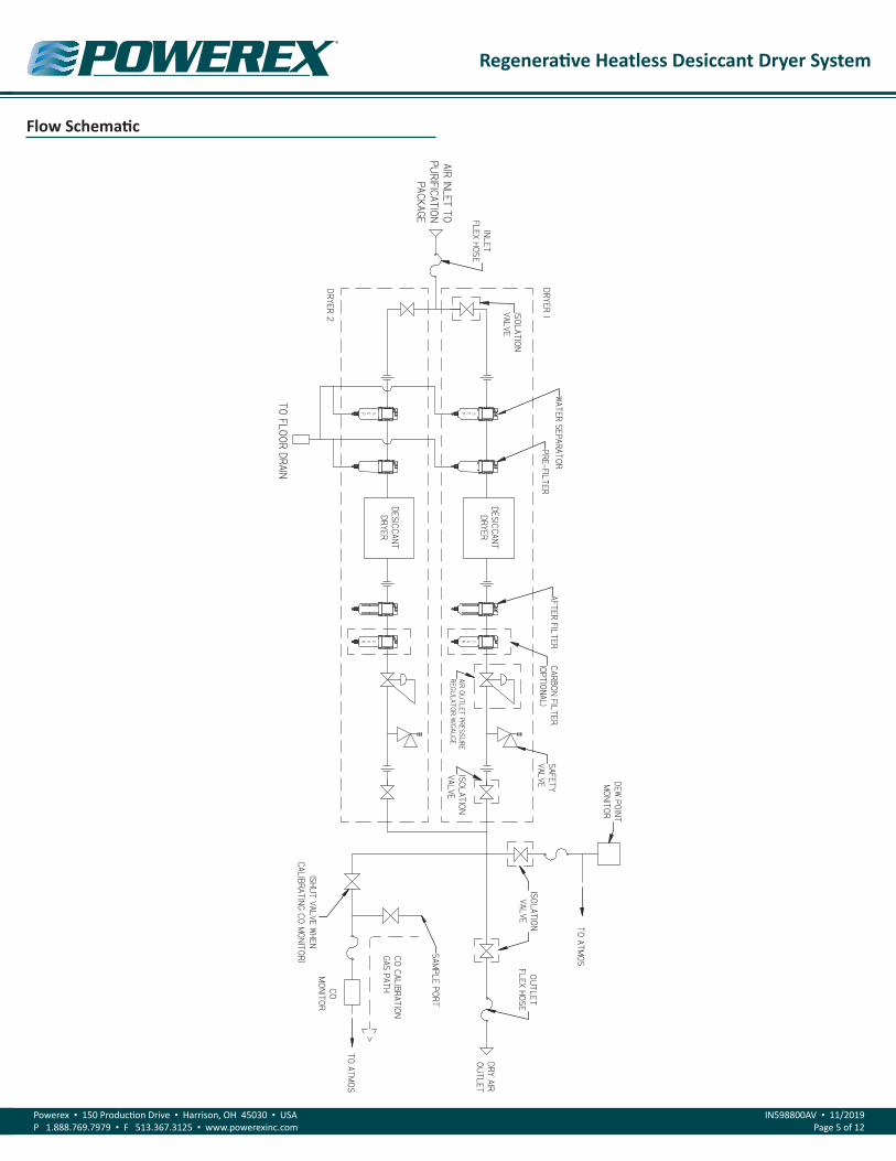
Dryer 1 & 2Each dryer is a regenerative heatless desiccant dryer. It employs
a pressure swing adsorption cycle and purge saving control system. Refer to page 6 for dryer flow schematic. The pre-filter equipped with a separator element prevents any liquids and particulates from entering the dryer. It comes with an automatic condensate drain valve and filter element change indicator. The after-filter stops any desiccant dust from leaving the dryer. It comes with an indicator as to when the element needs to be replaced. Each regulator is factory set at 55 PSIG and protected with a safety relief valve rated for 75 PSIG.
Regenerative Heatless Desiccant Dryer System
Powerex • 150 Production Drive • Harrison, OH 45030 • USAP 1.888.769.7979 • F 513.367.3125 • www.powerexinc.com
IN598800AV • 11/2019Page 3 of 12
Pressure Swing Adsorption CycleThe dryer uses a fully automatic pressure swing adsorption cycle in
which one tower is online in a drying phase while the other is offline either preparing or waiting for the next drying phase. The towers rotate between phases based on either time or dew point status, depending on the mode of operation.
The two phases are described below:
A. Drying Phase: A tower in a drying phase receives humid air through the pre-filter and then flows upward through the desiccant bed. At full system pressure the desiccant dehumidifies the air by means of adsorption. The dry air is then distributed out the top of the tower for different uses:
B. Regeneration Phase: Parallel to the tower in a drying phase the opposing tower is in one of four stages of the regeneration phase.
1. Expansion: The expansion stage takes place immediately after a tower switches from the drying phase to the regeneration phase. During this stage the tower pressure is expanded to ambient through the purge muffler over the course of a couple seconds, accompanied by a sudden blast.
2. Purge: A portion of the dry air from the opposing tower in the drying phase is bled through an orifice and directed through the top of the regenerating tower now at ambient pressure. The moisture stored in the desiccant bed is picked up by this dry air and expelled out the purge muffler.
3. Pressurize: After the tower is purged, the orifice continues to bleed dry air into the regenerated tower, building it up to system pressure. This prevents the dryer’s pre-filter and desiccant bed from being shocked with a blast of air upon tower switchover. Shocking a desiccant bed not only puts a strain on the effectiveness of the filtration and drying systems but can cause the desiccant material to dust. That dust will clog the afterfilter and decreases the dryer’s capacity to dry the air passing through it.
Tower SwitchoverWhen the dryer control system calls for a tower switchover, either
by reaching a certain time or dew point, the towers switch the function each is performing and the process starts over again.
InstallationInstallation Site
1. The dryer must be located in a clean, well lit and well ventilated area.
2. The installation site must be protected against the weather. The area should be free of excessive dust, toxic or flammable gases, moisture, water and direct sunlight.
3. Never install the dryer system where the ambient temperature will drop below +34oF or rise above +104oF or where humidity is high.
4. The installation area must be level, firm, and capable of holding the weight of the dryer system.
5. The site should provide sufficient spacing around the system in order to be able to carry out routine maintenance on each dryer. At least three feet is recommended from the front and sides of the dryer system.
6. Never install the dryer system outside.
Moving & SecuringIf it is necessary to move a freestanding dryer, proper technique
is extremely important. The dryer should only be lifted from its structural points such as the frame or tank brackets, never from its piping. Caution should be taken when lifting a dryer due to its high center of gravity. Once the dryer is in position, use suitable anchoring fasteners in all four holes provided to secure the dryer frame to the mounting location. Suitable vibration dampening devices should be used if that is a potential condition at the installation site.
Power ConnectionThe main dryer control box requires a stable 120VAC ± 10% OR
270VAC ± 10% (depending on model ordered). The individual dryer control boxes are pre-wired to that main panel. No other installation procedures to power the dryer are necessary.
WiringAll electrical connections to the main system control panel must
be performed by a qualified electrician. Installations must be in accordance with local and national electrical codes.
Dew Point Monitor ConnectionThe dew point monitor’s relay output contacts are wired to a relay
in the main system control panel. The individual dryer control boxes are pre-wired to that main panel. No other installation procedures to run the dryer in a dew point dependent mode are necessary.
ConnectionsThe dryer system inlet and outlet are equipped with female NPT
ports which differ in size depending on the dryer model. Ensure before plumbing in and out of the dryer that all compressed air lines are clean, undamaged, and won’t subject any stress to the dryer’s piping.
1. Make sure the piping is lined up without being strained or twisted when assembling the piping for the dryer.
2. Appropriate expansion loops or bends should be installed at the dryer to avoid stresses caused by changes in hot and cold conditions.
3. Piping supports should be anchored separately from the dryer to reduce noise and vibration.
4. Never use any piping smaller than the dryer connection.
5. Use flexible hose to connect the outlet of the dryer system to the customer piping so that the vibration of the dryer does not transfer to the piping.
Regenerative Heatless Desiccant Dryer System
Powerex • 150 Production Drive • Harrison, OH 45030 • USAP 1.888.769.7979 • F 513.367.3125 • www.powerexinc.com
IN598800AV • 11/2019Page 4 of 12
OperationBefore Start Up
1. Make sure all safety warnings, labels and instructions have been read and understood before continuing.
2. Remove any shipping materials.
3. Confirm that the electric power source and ground have been firmly connected.
4. Be sure all pressure connections are tight.
5. Check to be certain all safety valves, etc., are correctly installed.
6. Securely mount all panels and guards.
7. Check that all fuses, circuit breakers, etc., are the proper size.
8. Make sure the inlet and after filters are properly installed.
Turning the Dryer System OnThe dryer system is supplied power through a three position switch
on the main system control panel labeled Dryer 1— BOTH—Dryer 2. After the appropriate dryer is selected, that dryer’s control box has electric potential.
Start Up1. Ensure that all isolation valves (dryer, monitor, and source) are
closed.
2. Ensure the electrical connections are in safe contact and in good condition.
3. Ensure the compressed air system upstream of the dryer is pressurized.
4. At the main system control panel there will be a switch labeled Dryer 1—BOTH—Dryer 2. Place this switch to the Dryer 1 position. This will apply power to the dryer control box for Dryer 1.
5. SLOWLY open the inlet isolation valve to Dryer 1. Avoid sudden pressure build-up in every circumstance as it can cause damage to the dryer.
6. Dryer 1 will now begin cycling between its two desiccant towers.
7. Check for airflow from Dryer 1’s purge mufflers.
8. SLOWLY open Dryer 1’s outlet isolation valve, making sure the source valve is still closed.
9. SLOWLY open the monitor isolation valve(s) allowing air to flow to the CO and dew point monitor’s sensors.
10. Check for airflow from the dew point sensor’s orifice tube.
11. Allow the dryer to cycle in this state for at least 15 minutes. During this time, test all joints for any leaks using a leak detector spray or suitable alternative. Repair any detected leaks as they will cause degraded performance of the dryer.
12. Dryer 1 is now capable of drying air and switching into the economy mode.
13. SLIGHTLY open the outlet source valve and allow the
compressed air system downstream of the dryer to pressurize. This will prevent the dryer from being overloaded.
14. SLOWLY open the source valve to its fully open position. Dryer 1 is now in service and fully operational
OperationVariable Cycle
The drying and regenerating phases are based on an elapse of time as well as dew point. If the dew point is –10oF or above, the control system operates the dryer in the fixed cycle mode. In the case that the demand on the dryer is low and the dew point is below –15oF, the dryer will switch into an economy mode in which the purge flow is eliminated and the drying phase time is increased.
Regenerative Heatless Desiccant Dryer System
Powerex • 150 Production Drive • Harrison, OH 45030 • USAP 1.888.769.7979 • F 513.367.3125 • www.powerexinc.com
IN598800AV • 11/2019Page 5 of 12
Flow Schematic
DESICCANTDRYER
CAR
SAFETYVALVE
DRY AIRO
UTLET
CARBON FILTER
(OPTIONAL)
SEP
AFTER FILTERPRE-FILTER
SAMPLE PO
RT
COM
ONITOR
TO ATMOS
TO ATMOS
TO FLOOR DRAIN
WATER SEPARATO
R
DESICCANTDRYER
SEP
CAR
ISOLATION
VALVE
AIR INLET TOPU
RIFICATION
PACKAGE
ISOLATION
VALVEAIR OU
TLET PRESSURE
REGULATOR W
/GAUGE
DEW PO
INTM
ONITOR
CO CALIBRATIONGAS PATH
(SHUT VALVE W
HENCALIBRATING CO
MO
NITOR )
ISOLATION
VALVEO
UTLET
FLEX HOSE
IN592401AV PAGE 6
DRYER 1
DRYER 2
INLETFLEX HOSE
Regenerative Heatless Desiccant Dryer System
Powerex • 150 Production Drive • Harrison, OH 45030 • USAP 1.888.769.7979 • F 513.367.3125 • www.powerexinc.com
IN598800AV • 11/2019Page 6 of 12
MaintenancePreventive Maintenance Schedule
To ensure reliable, uninterrupted dryer operation, follow the recommended preventative maintenance schedule provided in the dryer manual. If done so, the dryer system should provide years of dependable service.
Monthly Switchover ProcedureIn order to maintain proper and unified performance from the
desiccant air dryer system, it is recommended that the dryers be alternated on a regular schedule (once every month). The following procedure explains alternating two systems, where Dryer 1 is the online dryer and Dryer 2 is the offline dryer.
1. At the main system control panel there will be a switch labeled Dryer 1—BOTH—Dryer 2. Place this switch to the BOTH position. This will apply power to both dryers’ control boxes.
2. SLOWLY open the inlet isolation valve to Dryer 2. Avoid sudden pressure build-up in every circumstance as it can cause damage to the dryer.
3. Dryer 2 will now begin cycling between its two towers.
4. Check for airflow from Dryer 2’s purge mufflers.
5. Allow both dryers to run for a period of 15 minutes to ready Dryer 2. At this point Dryer 2’s outlet isolation valve is still closed, and Dryer 1 remains the online dryer. During this time, test all plumbing joints on Dryer 2 for leaks with a leak detector spray or suitable alternative. Repair any detected leaks as they will cause degraded performance of the dryer.
6. SLOWLY open Dryer 2’s outlet isolation valve.
7. Close Dryer 1’s outlet isolation valve.
8. Wait 15 seconds for Dryer 1to fully pressurize and close Dryer 1’s inlet isolation valve.
9. At the main system control panel, rotate the dryer selector switch labeled Dryer 1—BOTH—Dryer 2 to the Dryer 2 position. Dryer 1is now dormant. Dryer 2 is in service and fully operational.
Maintenance Shut DownAll of the maintenance items that take place at 6 month intervals or
more require that the dryer be shut down in order for them to take place. The following procedure explains how to shut down a dryer that needs maintenance labor.
1. Bring the reserve dryer online by following steps 1 through 7 of the Monthly Switchover Procedure.
2. Close the outlet isolation valve of the dryer that needs maintenance.
3. Close the inlet isolation valve of the same dryer.
4. Rotate the dryer cycle switch on the main control box to the BOTH position and allow the dryer to continue cycling until the purge exhaust has fully depressurized all towers. Check all towers’ pressure gauge to confirm that the system is
depressurized.
5. At the main system control panel, rotate the dryer selector switch labeled Dryer 1—BOTH—Dryer 2 from the BOTH to whichever is now online.
6. Isolate and disconnect the electrical power to the dryer. Follow all Lock out/Tag out procedures while maintenance is being carried out.
Cleaning or Replacing the Prefilter's Auto Drain ValveThe auto drain valve is a float mechanism condensate trap. It
automatically opens and drains the collected condensate as soon as the level of fluid rises to lift the float. If the valve is suspected to be malfunctioning it should be cleaned or replaced. A typical characteristic of valve malfunction is a permanent flow noise from the drain outlet signifying the float mechanism is stuck open or the float mechanism is stuck closed indicated by water buildup in the bowl. In either case, the valve needs to be removed for cleaning or replacement. To do this:
1. First perform a maintenance shut down, making sure the dryer needing maintenance is fully depressurized and isolated from all electrical potential.
2. Remove the drain hose from the auto drain outlet.
3. Remove the filter bowl by twisting counter-clockwise.
4. Loosen and remove the retaining nut at the bottom of the filter bowl.
5. The auto drain valve can now be pushed out the top of the bowl to be cleaned or replaced.
6. Place the clean or new auto drain valve in the bowl and tighten the retaining nut.
7. Return the filter bowl securely to the body and the drain hose to the auto drain outlet.
Replacing the Filter ElementsThe filter elements will eventually become clogged with particulates
and contaminants and should be replaced at regular intervals. A clogged filter element creates too large of a pressure drop across the filter and can hurt the dryer’s performance. The differential pressure indicators on top of the filters will change from green to red when the pressure drop across the filter is too high, usually signaling an element that needs to be replaced.
1. First perform a maintenance shut down, making sure the dryer needing maintenance is fully depressurized and isolated from all electric potential.
2. Remove the filter bowl by twisting counter-clockwise.
3. Unscrew the filter element from the body and properly discard it.
4. Screw in the new element and replace the filter bowl securely.
5. Disposed of the old filter element in an environmentally safe way, in accordance with all current statutory regulations.
Regenerative Heatless Desiccant Dryer System
Powerex • 150 Production Drive • Harrison, OH 45030 • USAP 1.888.769.7979 • F 513.367.3125 • www.powerexinc.com
IN598800AV • 11/2019Page 7 of 12
Replacing the Purge MufflerThe purge muffler is a critical component of the dryer. If it becomes
clogged, dryer performance will degrade quickly due to the restraints on the purge stage of the regeneration phase. A characteristic of a clogged muffler is a tower pressure gauge reading anything but zero while that tower is purging.
1. First perform a maintenance shut down, making sure the dryer needing maintenance is fully depressurized and isolated from all electric potential.
Problem Cause Corrective Action
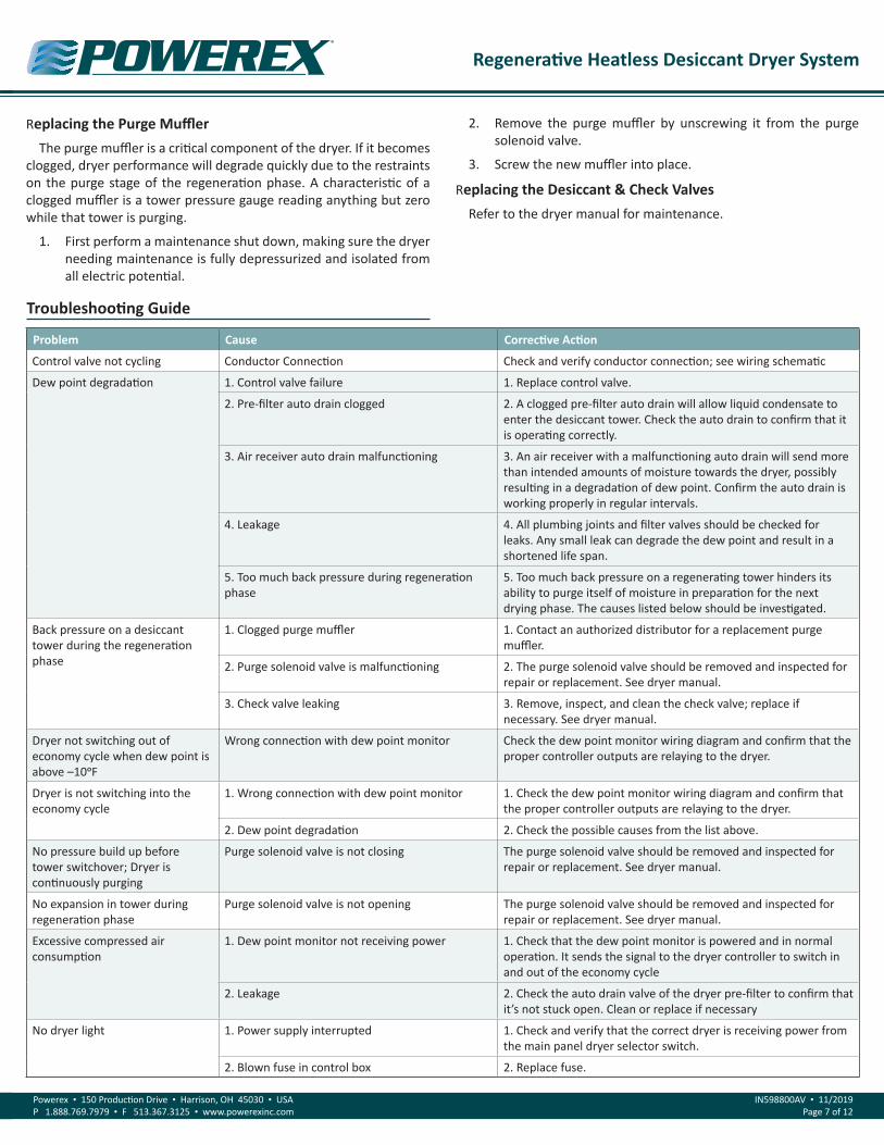
Control valve not cycling Conductor Connection Check and verify conductor connection; see wiring schematic
Dew point degradation 1. Control valve failure 1. Replace control valve.
2. Pre-filter auto drain clogged 2. A clogged pre-filter auto drain will allow liquid condensate to enter the desiccant tower. Check the auto drain to confirm that it is operating correctly.
3. Air receiver auto drain malfunctioning 3. An air receiver with a malfunctioning auto drain will send more than intended amounts of moisture towards the dryer, possibly resulting in a degradation of dew point. Confirm the auto drain is working properly in regular intervals.
4. Leakage 4. All plumbing joints and filter valves should be checked for leaks. Any small leak can degrade the dew point and result in a shortened life span.
5. Too much back pressure during regeneration phase
5. Too much back pressure on a regenerating tower hinders its ability to purge itself of moisture in preparation for the next drying phase. The causes listed below should be investigated.
Back pressure on a desiccant tower during the regeneration phase
1. Clogged purge muffler 1. Contact an authorized distributor for a replacement purge muffler.
2. Purge solenoid valve is malfunctioning 2. The purge solenoid valve should be removed and inspected for repair or replacement. See dryer manual.
3. Check valve leaking 3. Remove, inspect, and clean the check valve; replace if necessary. See dryer manual.
Dryer not switching out of economy cycle when dew point is above –10oF
Wrong connection with dew point monitor Check the dew point monitor wiring diagram and confirm that the proper controller outputs are relaying to the dryer.
Dryer is not switching into the economy cycle
1. Wrong connection with dew point monitor 1. Check the dew point monitor wiring diagram and confirm that the proper controller outputs are relaying to the dryer.
2. Dew point degradation 2. Check the possible causes from the list above.
No pressure build up before tower switchover; Dryer is continuously purging
Purge solenoid valve is not closing The purge solenoid valve should be removed and inspected for repair or replacement. See dryer manual.
No expansion in tower during regeneration phase
Purge solenoid valve is not opening The purge solenoid valve should be removed and inspected for repair or replacement. See dryer manual.
Excessive compressed air consumption
1. Dew point monitor not receiving power 1. Check that the dew point monitor is powered and in normal operation. It sends the signal to the dryer controller to switch in and out of the economy cycle
2. Leakage 2. Check the auto drain valve of the dryer pre-filter to confirm that it’s not stuck open. Clean or replace if necessary
No dryer light 1. Power supply interrupted 1. Check and verify that the correct dryer is receiving power from the main panel dryer selector switch.
2. Blown fuse in control box 2. Replace fuse.
Troubleshooting Guide
2. Remove the purge muffler by unscrewing it from the purge solenoid valve.
3. Screw the new muffler into place.
Replacing the Desiccant & Check ValvesRefer to the dryer manual for maintenance.
Regenerative Heatless Desiccant Dryer System
Powerex • 150 Production Drive • Harrison, OH 45030 • USAP 1.888.769.7979 • F 513.367.3125 • www.powerexinc.com
IN598800AV • 11/2019Page 8 of 12
Notes
Regenerative Heatless Desiccant Dryer System
Powerex • 150 Production Drive • Harrison, OH 45030 • USAP 1.888.769.7979 • F 513.367.3125 • www.powerexinc.com
IN598800AV • 11/2019Page 9 of 12
Notes
Regenerative Heatless Desiccant Dryer System
Powerex • 150 Production Drive • Harrison, OH 45030 • USAP 1.888.769.7979 • F 513.367.3125 • www.powerexinc.com
IN598800AV • 11/2019Page 10 of 12
Notes
Regenerative Heatless Desiccant Dryer System
Powerex • 150 Production Drive • Harrison, OH 45030 • USAP 1.888.769.7979 • F 513.367.3125 • www.powerexinc.com
IN598800AV • 11/2019Page 11 of 12
Powerex Limited Warranty – Applicable to Non-OEM Customers in the U.S. & Canada OnlyWarranty and Remedies.(a) General. Powerex warrants each Compressor System, Vacuum System, Vacuum Pump, Compressor Air-End, or Powerex branded Accessory (collectively “Products”, individually each a “Product”) to be free from defects in material and workmanship (“Defects”) at the date of shipment. This warranty shall apply only to Products that are purchased and used in the United States of America and in Canada. EXCEPT AS SET FORTH BELOW, NO OTHER WARRANTY, WHETHER EXPRESS OR IMPLIED, INCLUDING ANY WARRANTY OF MERCHANTABILITY OR FITNESS FOR A PARTIC-ULAR PURPOSE, SHALL EXIST IN CONNECTION WITH THE SALE OR USE OF SUCH PRODUCTS. TO THE EXTENT PERMITTED BY LAW, ANY AND ALL IMPLIED WARRANTIES ARE EXCLUDED. All warranty claims must be made in writing and delivered to Powerex in accordance with the procedures set forth on its website (www.powerexinc.com), or such claim shall be barred. Upon timely receipt of a warranty claim, Powerex shall inspect the Product claimed to have a Defect, and Powerex shall repair, or, at its option, replace, free of charge, any Product which it determines to have had a Defect; provided, however, that if circumstances are such as to preclude the remedying of Defect by repair or replacement, Powerex shall, upon return of the Product, refund to buyer any part of the purchase price of such Products paid to Powerex. Freight for returning Products to Powerex for inspection shall be paid by buyer. The warranties and remedies herein are the sole and exclusive remedy for any breach of warranty or for any other claim based on any Defect, or non-performance of the Products, whether based upon contract, warranty or negligence.
(b) (i) Standard Period of Warranty – Parts and Labor. The purchase of any system includes our standard warranty. Powerex warrants and rep-resents all Products shall be free from Defects for the first eighteen (18) months from the date of shipment by Powerex, or twelve (12) months from the documented date of startup, or five thousand (5,000) hours of use, whichever occurs first. During such warranty period, Powerex shall be fully liable for all Defects in the Products (the “Product Defects”), i.e., all costs of repair or replacement, which may include “in and out” charges, so long as the Products are located in the United States or Canada, and the Products are reasonably located and accessible by service personnel for removal. “In and out” charges include the costs of removing a Product from buyer’s equipment for repair or replacement.
(ii) Premium Period of Warranty – Parts and Labor. In order to be eligible for premium warranty coverage, a premium warranty for each sys-tem must be purchased when order is placed. Powerex warrants and represents all Products shall be free from Defects for the first thirty (30) months from the date of shipment by Powerex, or twenty-four (24) months from the documented date of startup, or seven thousand five hun-dred (7,500) hours of use, whichever occurs first. During such warranty period, Powerex shall be fully liable for all Defects in the Products (the “Product Defects”), i.e., all costs of repair or replacement, which may include “in and out” charges, so long as the Products are located in the United States or Canada, and the Products are reasonably located and accessible by service personnel for removal. “In and out” charges include the costs of removing a Product from buyer’s equipment for repair or replacement.
(c) Additional Period of Warranty – Parts Only (No Labor). In addition to the above, Powerex warrants each Powerex branded Compressor Air- End and Vacuum Pump shall be free of Defects for a period of forty-two (42) months from the date of shipment by Powerex, or thirty-six (36) months from the documented date of startup, or ten thousand (10,000) hours of use, whichever occurs first. Supplier’s repair or replacement of any Product shall not extend the period of any warranty of any Product. This warranty applies to the exchange of part(s) found to be defective by an Authorized Powerex Service Representative only.
(d) Replacement Pumps – Parts Only (No Labor). For any replacement Air-End or Vacuum Pumps installed on a Powerex manufactured system or unit after any initial warranty period has expired or where another warranty does not apply for any reason, Powerex warrants that the Air-End or Vacuum Pumps shall be free of Defects for a period of thirty-six (36) months from the date of shipment by Powerex or ten thousand (10,000) hours of use, whichever comes first. For any replacement Air-End or Vacuum Pumps installed on a system that was not manufactured by Powerex after any initial warranty period has expired or where another warranty does not apply for any reason, Powerex warrants that the Air-End or Vacuum Pumps shall be free of Defects for the first twelve (12) months from the date of shipment by Powerex. Supplier’s repair or replacement of any Product shall not extend the period of any warranty of any Product. This warranty applies to the exchange of part(s) found to be defective by an Authorized Powerex Service Representative only.
(e) Replacement Motors – Parts Only (No Labor). For any replacement motor installed on a Powerex manufactured system or unit after any initial warranty period has expired or where another warranty does not apply for any reason, Powerex warrants that the replacement motor shall be free of Defects for the first twelve (12) months from the date of shipment by Powerex. For any replacement motor installed on a system or unit that was not manufactured by Powerex after any initial warranty period has expired or where another warranty does not apply for any reason, Powerex warrants that the replacement motor shall be free of Defects for the first ninety (90) days from the date of shipment by Pow-erex. Supplier’s repair or replacement of any Product shall not extend the period of any warranty of any Product. This warranty applies to the exchange of part(s) found to be defective by an Authorized Powerex Service Representative only.
(f) Replacement Parts – Parts Only (No Labor). For other replacement parts besides motors, Air-End or Vacuum Pumps installed on a Powerex manufactured system or unit after any initial warranty period has expired or where another warranty does not apply for any reason, Powerex warrants that such replacement parts will be free from Defects for the first twelve (12) months from the date of shipment by Powerex. For other replacement parts besides motors, Air-End or Vacuum Pumps installed on a system or unit that was not manufactured by Powerex after any
Regenerative Heatless Desiccant Dryer System
Powerex • 150 Production Drive • Harrison, OH 45030 • USAP 1.888.769.7979 • F 513.367.3125 • www.powerexinc.com
IN598800AV • 11/2019Page 12 of 12
initial warranty period has expired or where another warranty does not apply for any reason, Powerex warrants that such replacement parts will be free from Defects for the first twelve (12) months from the date of shipment by Powerex. For other replacement parts besides motors, Air-End or Vacuum Pumps installed on a system or unit that was not manufactured by Powerex after any initial warranty period has expired or where another warranty does not apply for any reason, Powerex makes no warranties. Supplier’s repair or replacement of any Product shall not extend the period of any warranty of any Product. This warranty applies to the exchange of part(s) found to be defective by an Authorized Powerex Service Representative only.
(g) Coverage. The warranty provided herein applies to Powerex manufactured units or systems only.
(h) Exceptions. Notwithstanding anything to the contrary herein, Powerex shall have no warranty obligations with respect to Products:
(i) That have not been installed in accordance with Powerex’s written specifications and instructions;
(ii) That have not been maintained in accordance with Powerex’s written instructions;
(iii) That have been materially modified without the prior written approval of Powerex; or
(iv) That experience failures resulting from operation, either intentional or otherwise, in excess of rated capacities or in an otherwise im-proper manner.
The warranty provided herein shall not apply to: (i) any defects arising from corrosion, abrasion, use of insoluble lubricants, or negligent at-tendance to or faulty operation of the Products; (ii) ordinary wear and tear of the Products; or (iii) defects arising from abnormal conditions of temperature, dirt or corrosive matter; (iv) any OEM component which is shipped by Powerex with the original manufacturer’s warranty, which shall be the sole applicable warranty for such component.
Limitation of Liability. NOTWITHSTANDING ANYTHING TO THE CONTRARY HEREIN, TO THE EXTENT ALLOWABLE UNDER APPLICABLE LAW, UN-DER NO CIRCUMSTANCES SHALL POWEREX BE LIABLE FOR ANY INCIDENTAL, CONSEQUENTIAL, PUNITIVE, SPECULATIVE OR INDIRECT LOSSES OR DAMAGES WHATSOEVER ARISING OUT OF OR IN ANY WAY RELATED TO ANY OF THE PRODUCTS OR GOODS SOLD OR AGREED TO BE SOLD BY POWEREX TO BUYER. TO THE EXTENT ALLOWABLE UNDER APPLICABLE LAW, POWEREX’S LIABILITY IN ALL EVENTS IS LIMITED TO, AND SHALL NOT EXCEED, THE PURCHASE PRICE PAID.
Warranty Disclaimer. Powerex has made a diligent effort to illustrate and describe the Products in its literature, including its Price Book, accu-rately; however, such illustrations and descriptions are for the sole purpose of identification, and do not express or imply a warranty that the Products are merchantable, or fit for a particular purpose, or that the Products will necessarily conform to the illustrations or descriptions.
Product Suitability. Many jurisdictions have codes and regulations governing sales, construction, installation, and/or use of Products for certain purposes, which may vary from those in neighboring areas. While Powerex attempts to assure that its Products comply with such codes, it can-not guarantee compliance, and cannot be responsible for how the product is installed or used. Before purchase and use of a Product, please review the Product applications, and national and local codes and regulations, and be sure that the Product, installation, and use will comply with them.
Claims. Any non-warranty claims pertaining to the Products must be filed with Powerex within 6 months of the invoice date, or they will not be honored. Prices, discounts, and terms are subject to change without notice or as stipulated in specific Product quotations. Powerex shall not be liable for any delay or failure arising out of acts of the public enemy, fire, flood, or any disaster, labor trouble, riot or disorder, delay in the supply of materials or any other cause, whether similar or dissimilar, beyond the control of Company. All shipments are carefully inspected and counted before leaving the factory. Please inspect carefully any receipt of Products noting any discrepancy or damage on the carrier’s freight bill at the time of delivery. Discrepancies or damage which obviously occurred in transit are the carrier’s responsibility and related claims should be made promptly directly to the carrier. Returned Products will not be accepted without prior written authorization by Powerex and deductions from invoices for shortage or damage claims will not be allowed. UNLESS OTHERWISE AGREED TO IN WRITING, THE TERMS AND CONDITIONS CONTAINED IN THIS LIMITED WARRANTY WILL CONTROL IN ANY TRANSACTION WITH POWEREX. Any different or conflicting terms as may appear on any order form now or later submitted by the buyer will not control. All orders are subject to acceptance by Powerex.