REHABILITATION OF THE CHICAGO SHORELINE: A COASTAL ENGINEERING PERSPECTIVE Michael Krecic, P.E. Senior Engineer Taylor Engineering, Inc. 9000 Cypress Green Drive Jacksonville, FL 32256 Mark Wagstaff, P.E. Project Manager MWH 175 W. Jackson Boulevard Chicago, IL 60604 ABSTRACT Chicago’s Lake Michigan shoreline protection consists of stepped revetments, rubblemound revetments, beaches, groins, and offshore breakwaters. Primarily constructed in the early twentieth century, this man-made shoreline provides for over 24 miles of public parkland; a key component in the city’s quality of life. Because of fluctuating lake levels and severe wave conditions, the revetments have failed in many sections, leaving the parkland exposed, and the lakeward edge of the promenade has fallen into the water. The City of Chicago, in partnership with the U.S. Army Corps of Engineers, sponsors an ambitious rebuilding effort, known as the Chicago Shoreline Protection Project, to restore eight miles of the deteriorated shoreline. With an approximate budget of $300 million, the project includes construction of sheet pile and concrete-stepped revetments, beaches’ stabilization, and rubblemound structures (breakwaters and revetments). Additional amenity improvements include the construction of piers, creation and restoration of habitat, the provision of greater accessibility to the waterfront, and management of natural resources. INTRODUCTION Because of varying water levels and depths and shoreline composition, four different types of shore protection systems have protected the Chicago shoreline for more than 60 years. These types include step stone revetments, rubblemound revetments, beaches and groins, and offshore breakwaters. Figures 1 – 4 present examples of each structure found along the shoreline. Most of Chicago’s original shoreline consists of the step stone revetment. The step stone revetments generally include rock-filled cribs placed about 1,000 feet (ft) offshore and fill placed landward of the cribs. Typically, a 20-ft wide double row of timber pilings formed the crib walls. On top of rock and fill sat capstones, large limestone blocks, which formed a series of steps to provide easy access to the water’s edge. To a much less extent, rubbemound revetments also exist along the shoreline. These structures provide unsafe access to the public areas of the shoreline. Beaches and groins, however, provide the most recreational opportunities for the public. Submerged bulkheads hold the toe of some beach fill to create a perched beach in large water depths. Others without offshore structures generally align northeasterly with a downdrift groin to retain the fill.
Transcript
REHABILITATION OF THE CHICAGO SHORELINE: A COASTAL ENGINEERING PERSPECTIVE
Michael Krecic, P.E.
Senior Engineer Taylor Engineering, Inc.
9000 Cypress Green Drive Jacksonville, FL 32256
Mark Wagstaff, P.E. Project Manager
MWH 175 W. Jackson Boulevard
Chicago, IL 60604 ABSTRACT
Chicago’s Lake Michigan shoreline protection consists of stepped revetments, rubblemound revetments, beaches, groins, and offshore breakwaters. Primarily constructed in the early twentieth century, this man-made shoreline provides for over 24 miles of public parkland; a key component in the city’s quality of life. Because of fluctuating lake levels and severe wave conditions, the revetments have failed in many sections, leaving the parkland exposed, and the lakeward edge of the promenade has fallen into the water. The City of Chicago, in partnership with the U.S. Army Corps of Engineers, sponsors an ambitious rebuilding effort, known as the Chicago Shoreline Protection Project, to restore eight miles of the deteriorated shoreline. With an approximate budget of $300 million, the project includes construction of sheet pile and concrete-stepped revetments, beaches’ stabilization, and rubblemound structures (breakwaters and revetments). Additional amenity improvements include the construction of piers, creation and restoration of habitat, the provision of greater accessibility to the waterfront, and management of natural resources. INTRODUCTION
Because of varying water levels and depths and shoreline composition, four different types of shore protection systems have protected the Chicago shoreline for more than 60 years. These types include step stone revetments, rubblemound revetments, beaches and groins, and offshore breakwaters. Figures 1 – 4 present examples of each structure found along the shoreline.
Most of Chicago’s original shoreline consists of the step stone revetment. The
step stone revetments generally include rock-filled cribs placed about 1,000 feet (ft) offshore and fill placed landward of the cribs. Typically, a 20-ft wide double row of timber pilings formed the crib walls. On top of rock and fill sat capstones, large limestone blocks, which formed a series of steps to provide easy access to the water’s edge. To a much less extent, rubbemound revetments also exist along the shoreline. These structures provide unsafe access to the public areas of the shoreline. Beaches and groins, however, provide the most recreational opportunities for the public. Submerged bulkheads hold the toe of some beach fill to create a perched beach in large water depths. Others without offshore structures generally align northeasterly with a downdrift groin to retain the fill.
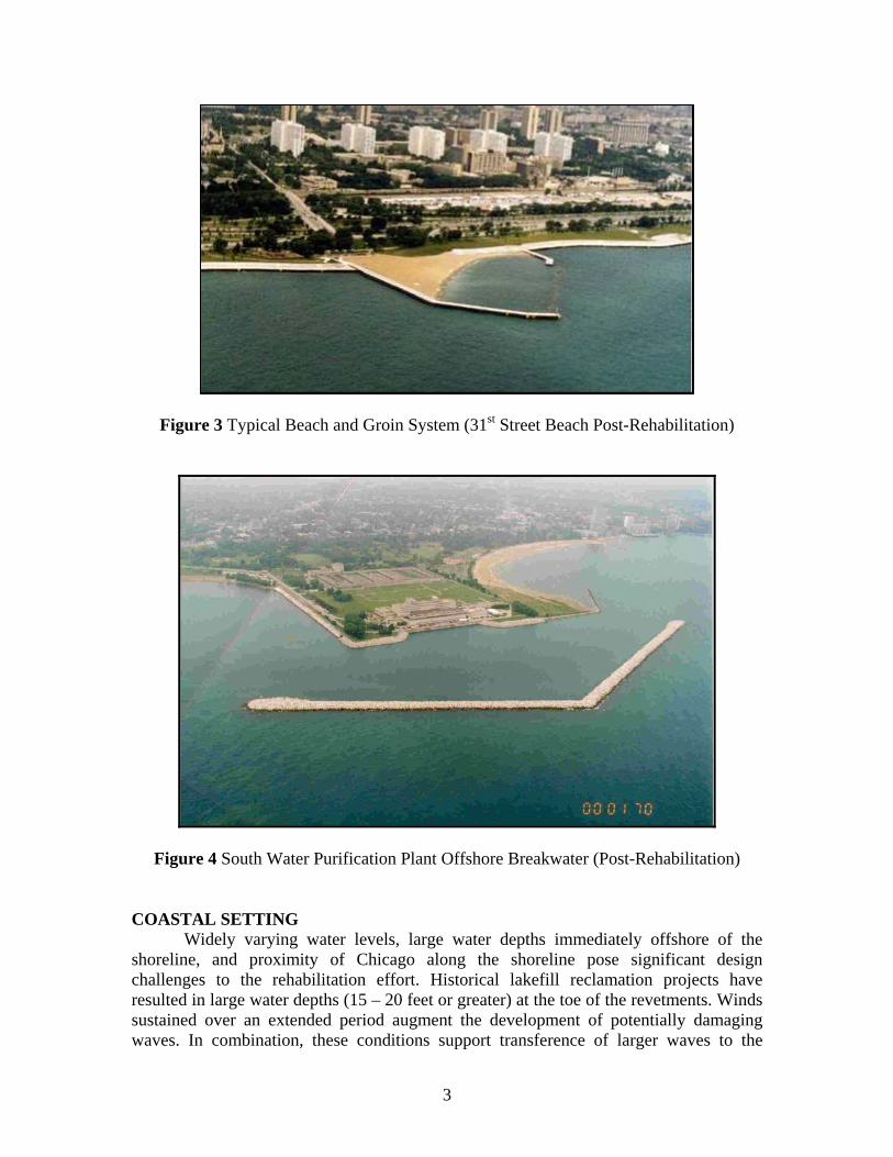
Finally, a 2,600-ft-long rubblemound breakwater protects the South Water Purification Plant, a drinking water facility, at 79th Street.
Figure 1 Typical Historical Step Stone Revetment Section
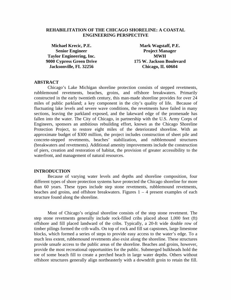
Figure 3 Typical Beach and Groin System (31st Street Beach Post-Rehabilitation)
Figure 4 South Water Purification Plant Offshore Breakwater (Post-Rehabilitation)
COASTAL SETTING Widely varying water levels, large water depths immediately offshore of the
shoreline, and proximity of Chicago along the shoreline pose significant design challenges to the rehabilitation effort. Historical lakefill reclamation projects have resulted in large water depths (15 – 20 feet or greater) at the toe of the revetments. Winds sustained over an extended period augment the development of potentially damaging waves. In combination, these conditions support transference of larger waves to the
3
nearshore region, increase the amount of wave overtopping, and increase the potential for flooding damage.
Water Level Water level fluctuations in Lake Michigan exhibit several temporal variations.
Generally, Lake Michigan water levels rise during the spring and summer seasons and fall during the winter season. Over longer periods, monthly mean water levels may vary significantly (Figure 5). For example, the record low water level occurred in 1964 (-1.45 ft LWD) and the record high water level occurred in 1986 (4.85 ft LWD). Changes in precipitation and evaporation patterns over the Great Lakes drainage basin results in these long-term water level fluctuations. Atmospheric conditions such as barometric pressure and wind direction may cause short-term, local fluctuations in water levels ranging from a couple of inches to several feet.
Figure 5 Lake Michigan Monthly Mean Still Water Level Fluctuations (1918 – 2003)
Fluctuating water levels require that one design shoreline protection and access structures to allow maximum use over the entire range of expected water levels. One must design a shore protection structure device sufficiently capable of dissipating wave energy and limiting overtopping from severe storms that occur during periods of high water levels without becoming so substantial that during periods of low water levels, recreational benefits become unrealized. Consideration of the design range for water
4
levels requires balancing the acceptability of an emergent structure during low water level periods and the required standard of protection during high water level periods.
The water level gage, with coordinates 41.73°N, 87.54°W, most representative of
water level fluctuations for the project, lies near Calumet Harbor, Illinois. The National Oceanic and Atmospheric Administration has operated and maintained this gage (908-7044) since 1903. The USACE (1993b) reports frequency of occurrence for design high water level (DWL) for this gage based on 1915 – 1989 data. Table 1 presents a summary of these design high water levels. The reported water levels include the still water level (SWL) plus the water level rise, which includes wind setup — the difference in still water levels on the windward and leeward sides of a body of water caused by wind stresses on the surface of the water.
Table 1 Extreme Water Levels1
Return Period(yrs) DWL
2 4.0 5 5.1 10 5.6 20 5.9 50 6.6 100 7.0
1 From USACE (1993b)
Wave Climate
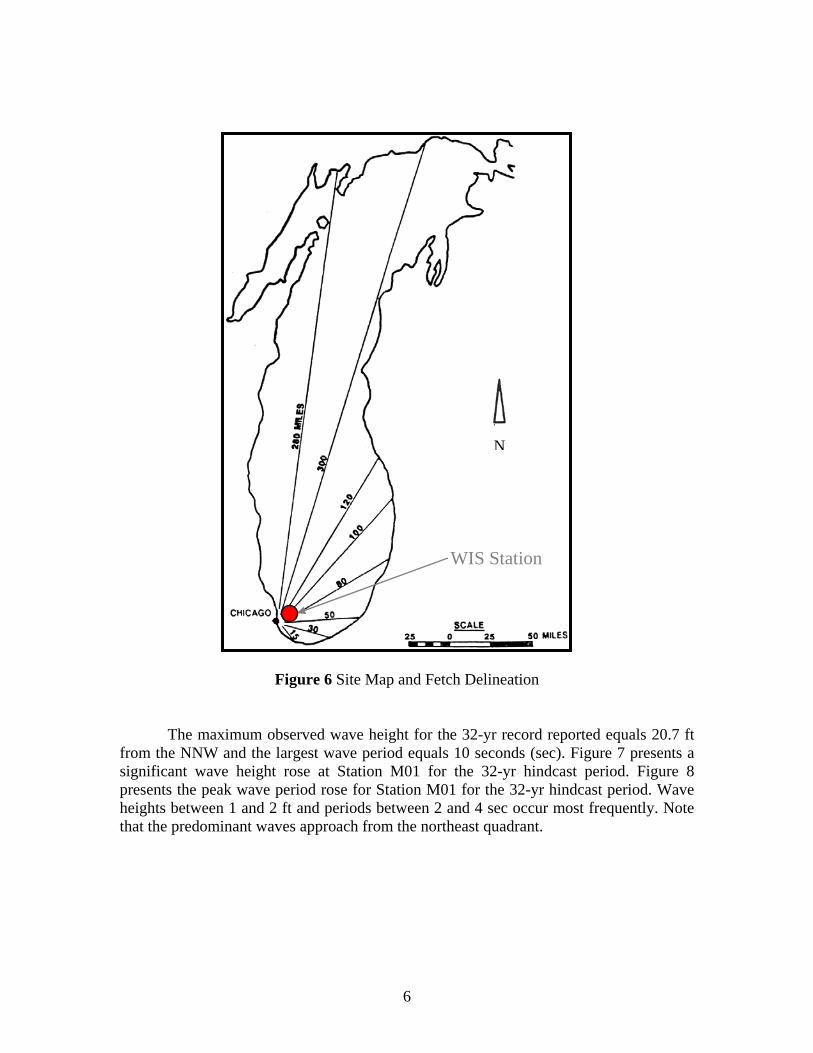
The City of Chicago lies on the southwest shore of Lake Michigan (Figure 6). Generally, winds from the north and east create the most critical conditions at Chicago’s lakefront because of greater available fetch lengths (200 – 300 miles) over Lake Michigan.
Offshore Wave Climate The USACE Wave Information Study (WIS) provides a 32-yr wave hindcast
dataset, 1956 – 1987, at select locations along Lake Michigan (Hubertz et al., 1991). Wave hindcast data, reported three-hourly, includes wave height (Hs), wave period (Tp), wave direction, wind speed, and wind direction. The USACE, on their web page, also provides wave hindcast data from 1988 – 1997. It recommends not combining these datasets into one, blended dataset. To characterize the nearshore wave climate along the entire project area, this design analysis selected the 1956 – 1987 dataset for WIS Station M01 (41.81°N, 87.38°W), located in 13-m (43-ft) water depth.
5
N
WIS Station
Figure 6 Site Map and Fetch Delineation The maximum observed wave height for the 32-yr record reported equals 20.7 ft
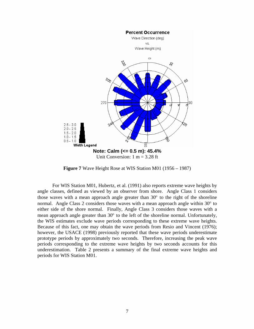
from the NNW and the largest wave period equals 10 seconds (sec). Figure 7 presents a significant wave height rose at Station M01 for the 32-yr hindcast period. Figure 8 presents the peak wave period rose for Station M01 for the 32-yr hindcast period. Wave heights between 1 and 2 ft and periods between 2 and 4 sec occur most frequently. Note that the predominant waves approach from the northeast quadrant.
6
Note: Calm (<= 0.5 m): 45.4%
Unit Conversion: 1 m = 3.28 ft
Figure 7 Wave Height Rose at WIS Station M01 (1956 – 1987)
For WIS Station M01, Hubertz, et al. (1991) also reports extreme wave heights by angle classes, defined as viewed by an observer from shore. Angle Class 1 considers those waves with a mean approach angle greater than 30° to the right of the shoreline normal. Angle Class 2 considers those waves with a mean approach angle within 30° to either side of the shore normal. Finally, Angle Class 3 considers those waves with a mean approach angle greater than 30° to the left of the shoreline normal. Unfortunately, the WIS estimates exclude wave periods corresponding to these extreme wave heights. Because of this fact, one may obtain the wave periods from Resio and Vincent (1976); however, the USACE (1998) previously reported that these wave periods underestimate prototype periods by approximately two seconds. Therefore, increasing the peak wave periods corresponding to the extreme wave heights by two seconds accounts for this underestimation. Table 2 presents a summary of the final extreme wave heights and periods for WIS Station M01.
7
Figure 8 Wave Period Rose at WIS Station M01 (1956 – 1987)
Table 2 Extreme Wave Heights and Periods Angle Class 1 Angle Class 2 Angle Class 3 Tr
Nearshore Wave Climate The parameters described above and the complex relationship of other factors
such as water levels, offshore depth and bathymetry, shoreline orientation, type of shoreline protection, wave refraction, and wave diffraction and reflection of waves from other structures govern the site-specific and temporal variations in wave climate on the lakefront. Understanding the nearshore wave climate and wave-induced forces on coastal structures allows designers to make better engineering judgments. Typical wave transformation methods employed include desktop assessment techniques such as Goda’s random wave method (e.g., Goda, 2000); however, because of the presence of the irregular nearshore bathymetry, simplistic wave transformation analyses sometimes prove
8
9
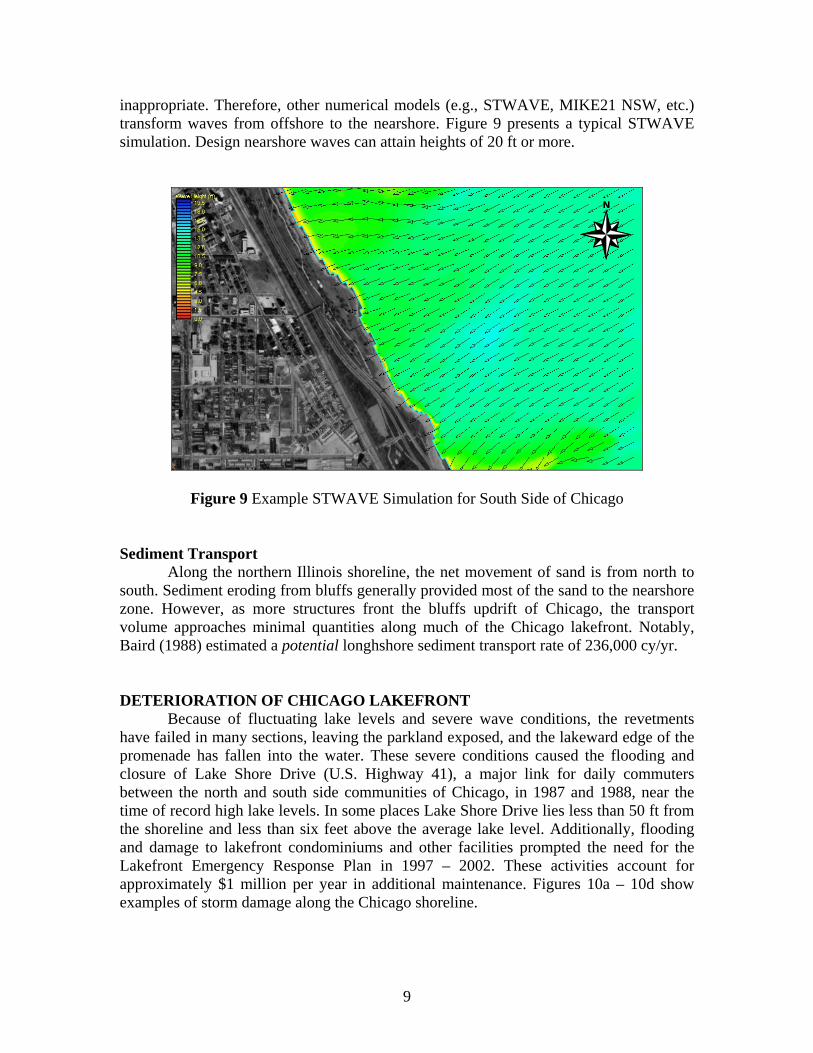
inappropriate. Therefore, other numerical models (e.g., STWAVE, MIKE21 NSW, etc.) transform waves from offshore to the nearshore. Figure 9 presents a typical STWAVE simulation. Design nearshore waves can attain heights of 20 ft or more.
Figure 9 Example STWAVE Simulation for South Side of Chicago
Sediment Transport Along the northern Illinois shoreline, the net movement of sand is from north to
south. Sediment eroding from bluffs generally provided most of the sand to the nearshore zone. However, as more structures front the bluffs updrift of Chicago, the transport volume approaches minimal quantities along much of the Chicago lakefront. Notably, Baird (1988) estimated a potential longhshore sediment transport rate of 236,000 cy/yr.
DETERIORATION OF CHICAGO LAKEFRONT Because of fluctuating lake levels and severe wave conditions, the revetments
have failed in many sections, leaving the parkland exposed, and the lakeward edge of the promenade has fallen into the water. These severe conditions caused the flooding and closure of Lake Shore Drive (U.S. Highway 41), a major link for daily commuters between the north and south side communities of Chicago, in 1987 and 1988, near the time of record high lake levels. In some places Lake Shore Drive lies less than 50 ft from the shoreline and less than six feet above the average lake level. Additionally, flooding and damage to lakefront condominiums and other facilities prompted the need for the Lakefront Emergency Response Plan in 1997 – 2002. These activities account for approximately $1 million per year in additional maintenance. Figures 10a – 10d show examples of storm damage along the Chicago shoreline.
NN
a) 40th Street Wave Overtopping b) Flooding of Lakeshore Drive
c) Deterioration along North Side d) Deterioration along South Side
mFigure 10 Examples of Storm Da age and Revetment Deterioration
10
REBUILDING OF CHICAGO LAKEFRONT Chicago Shoreline Protection Project
The Chicago Shoreline Protection Project covers eight miles of shoreline (about one-third of the Chicago shoreline) for a project cost of $300 million. The USACE and the City of Chicago established a Project Cooperation Agreement wherein the original schedule called for construction between 1995 and 2005. A slow down in the federal funding stream (due to other, non-domestic programs) will move the project completion date back to around 2008 – 2010. A cost share agreement of 35% of the National Economic Development (NED) plan, a rubblemound revetment, forms a basis of the local funding commitments. However, the locally-preferred plan (the step stone revetment — the selected alternative) increases the actual local sponsor project cost, raising the local share to around 50%. Local agreements with the Chicago Park District and the State of Illinois (Illinois Department of Natural Resources) spread the local sponsor program costs.
The primary objectives of the Chicago Shoreline Protection Project consist of
flood and storm damage reduction and erosion prevention. A subsequent benefit of the proposed structures includes the provision of public access, accounting for the Americans with Disabilities Act (ADA) guidelines. Where appropriate, the project incorporates additional features (betterments – not funded by USACE) to better serve the public.
While the overall project also includes the reconstruction of a 2,600-foot long
offshore breakwater, existing beach stabilization and a creation of a completely new beach, this paper focuses on the predominant feature of the program – the reconstruction of the shoreline revetments.
How Did Old Revetment Fail? Since the time of their original construction, Chicago’s revetments have required
periodic maintenance and rehabilitation. Records in the Chicago Park District archive document repairs implemented after storm damage, including re-setting and/or grouting of the limestone blocks, throughout the 1930s, 40s and 50s. Unprecedented low lake levels in the early 1960s exposed a greater portion of the vertical timber piles, in particular the area around the connection with the horizontal tie rods. Deterioration of the wood, combined with increasing lake levels (and associated incident wave energy) through the 1970s and 1980s lead to loss of structural integrity. Broken stone retained by the wooden cribs spilled out onto the lakebed, and the limestone blocks settled, broke, tipped and fell into the lake. Over time the stepped revetment in many places became indistinguishable from a rubblemound.
New Revetment Characteristics The proposed structures maintain the overall profile style of many of the original
revetments – a vertical seawall, with a wide lower level or promenade backed by a series
11
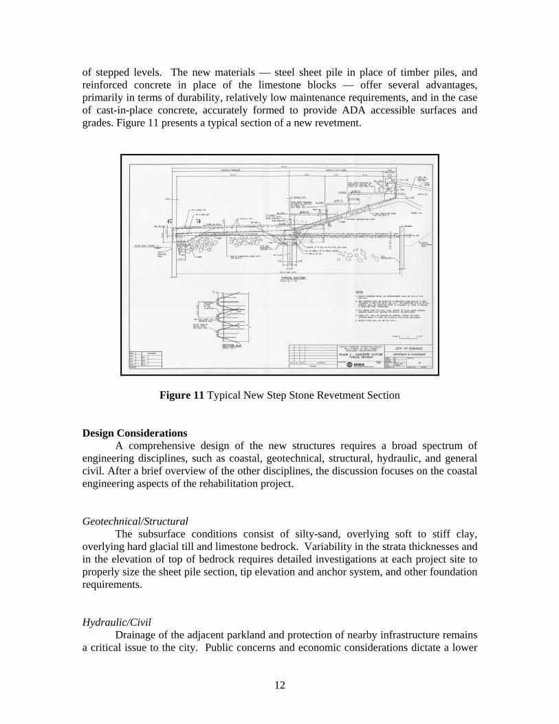
of stepped levels. The new materials — steel sheet pile in place of timber piles, and reinforced concrete in place of the limestone blocks — offer several advantages, primarily in terms of durability, relatively low maintenance requirements, and in the case of cast-in-place concrete, accurately formed to provide ADA accessible surfaces and grades. Figure 11 presents a typical section of a new revetment.
Figure 11 Typical New Step Stone Revetment Section
Design Considerations A comprehensive design of the new structures requires a broad spectrum of
engineering disciplines, such as coastal, geotechnical, structural, hydraulic, and general civil. After a brief overview of the other disciplines, the discussion focuses on the coastal engineering aspects of the rehabilitation project.
Geotechnical/Structural The subsurface conditions consist of silty-sand, overlying soft to stiff clay,
overlying hard glacial till and limestone bedrock. Variability in the strata thicknesses and in the elevation of top of bedrock requires detailed investigations at each project site to properly size the sheet pile section, tip elevation and anchor system, and other foundation requirements.
Hydraulic/Civil Drainage of the adjacent parkland and protection of nearby infrastructure remains
a critical issue to the city. Public concerns and economic considerations dictate a lower
12
revetment elevation than necessary to completely eliminate overtopping during storm events. Consequently, a series of backshore drainage paths (mildly sloping swales) directs overtopping water towards a “drainage gap,” where the waters can return to the lake. Local permitting requirements limit all such flows to overland, rather than underground collection and sewer systems. In a few cases, the adjacent parkland exceeds the revetment crest, thereby, eliminating the need for the drainage gaps/swales.
Coastal
The USACE recommends designing for the “20/10” condition, considered the larger of the combination of the 20-yr wave and 10-yr water level, or vice versa, for Great Lakes structural design. The USACE (1998) hypothesizes this event occurs on average once every 111 to 200 yrs. One typically applies the 20/10 condition for assessing structural stability (i.e., armor stone stability and wave forces on vertical walls); however, depending on one’s risk tolerance, assessment of other conditions for flooding (i.e., level of wave runup and overtopping protection) may require examination of other storm events.
Wave Overtopping
Given the little available guidance to estimate wave overtopping on the proposed vertical-walled, stepped revetments, Ward (2003) performed physical modeling in 1997 and 2001 at the USACE Coastal Hydraulic Laboratory (CHL) in the Waterways Experiment Station. Ward tested numerous cross sections and configurations including offshore breakwaters and large toe berms. These physical model tests resulted in a predictive formula which includes promenade elevation, crest elevation, and depth at structure toe. Notably, Krecic and Sayao (2004) developed an alternate predictive formula that includes revetment width as another parameter.
The overtopping criterion for design depends on the function and degree of
protection required. The allowable overtopping criterion for “Damage if promenade not paved,” i.e., 50 liters per second per meter of structure length (l/s/m) (0.54 cubic feet per second [cfs/ft]) (see e.g., Franco and Franco, 1994) applies at the site to minimize damage to the structure. Given some pavement behind the structure, one may increase the allowable overtopping limit to 200 l/s/m (2.16 cfs/ft). Most revetment designs allow for overtopping rate of approximately 1 cfs/ft and convey the discharge via swales back thru drainage gaps in the revetment. Because of this allowance, the designs also incorporate soil reinforcement just behind the top step of the revetment to prevent erosion.
Toe Protection Scour-induced erosion occurs at vertical sheet pile structures when scour
undermines the structure toe so that the wall rotates lakeward due to the pressure of the retained soil. To prevent waves from scouring its front, the sheet pile wall requires toe scour protection. The toe berm width from the sheet pile wall must cover the zone of
13
14
passive earth support in front of the wall. The SPM recommends a design berm width based on the maximum of three conditions: 1) twice the depth of sheet pile penetration, 2) twice the design wave height, and 3) 0.4 times the water depth. For the Chicago Shoreline Protection Project, the first condition, which applies to shallow-driven piles, usually results in excessive toe berm widths. Of the above conditions, condition two generally drives the toe berm width; derived widths generally approach 15 – 30 ft. Application of Tanimoto et al. (1982) method or Hudson (or van der Meer) formula, if outside limits of Tanimoto method, yields toe armor stone sizes. Based on these formulas, typical stone sizes approach 3 – 10 tons. Unlike most revetment elements, low lake level conditions generally produce worst-case toe stone sizes.
Wave Forces The stability of a coastal structure depends its ability to withstand wave forces.
The wave forces at a structure depend on the depth and slope of the lakebed in front of the structure as well as the steepness and direction of the waves. Wave pressure derivation employs the method outlined in Goda (2000). He recommends use of the maximum nearshore wave height to assess wave-loading conditions. The method, appropriate for breaking and non-breaking waves, separates wave pressures acting on the structure into pressure due to a wave crest and pressure due to a wave trough. Other traditional methods such as Minikin (e.g., SPM) yield much larger pressures for design. Design wave crest pressures on the sheet pile wall generally approach 40,000 lb/ft. Design wave trough pressures can exceed 10,000 lb/ft.
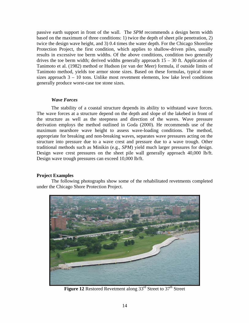
Project Examples The following photographs show some of the rehabilitated revetments completed
under the Chicago Shore Protection Project.
Figure 12 Restored Revetment along 33rd Street to 37th Street
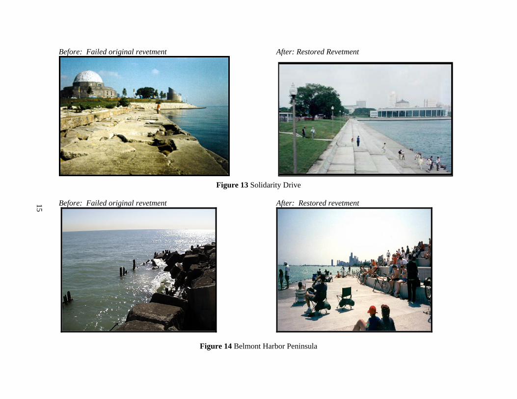
Before: Failed original revetment After: Restored Revetment
Figure 13 Solidarity Drive
Before: Failed original revetment After: Restored revetment
Figure 14 Belmont Harbor Peninsula
15
CONCLUSION The City of Chicago possesses a unique urban shoreline with parkland and open
space along most of the 24-mile shoreline. The City of Chicago, in partnership with the U.S. Army Corps of Engineers, sponsors an ambitious rebuilding effort, known as the Chicago Shoreline Protection Project, to restore eight miles of the deteriorated shoreline. With an approximate budget of $300 million, the project includes construction of sheet pile and concrete-stepped revetments, beaches’ stabilization, and rubblemound structures (breakwaters and revetments). Widely varying water levels, large water depths immediately offshore of the shoreline, and proximity of Chicago along the shoreline pose significant design challenges to the rehabilitation effort.
REFERENCES Franco, L., M. de Gerloni, M., and Franco. 1994. Wave Overtopping on Vertical and
Composite Breakwaters. In Edge, B.L. (Ed.) Coastal Engineering 1994, Proceedings, 24th International Conference on Coastal Engineering, Kobe, Japan. American Society of Civil Engineers, New York.
Goda, Y. 2000. Random Seas and Design of Maritime Structures (2nd Ed.). World Scientific, River Edge, NJ.
Hubertz, J.M., D.B. Driver, and R.B. Reinhard. 1991. Hindcast Wave Information for the Great Lakes: Lake Michigan. WIS Report No. 24. Waterways Experiment Station, Coastal Engineering Research Center, Vicksburg, MS.
Krecic, M.R. and Sayao, O.J. 2004. Wave Overtopping on Chicago Shoreline Revetment. In Melby, J. (Ed.) Coastal Structures ‘03. American Society of Civil Engineers, Reston, VA.
Resio, D.T. and Vincent, C.L. 1976. Design Wave Information for the Great Lakes: Report 3, Lake Michigan. Technical Report H-76-1. Waterways Experiment Station, Coastal Engineering Research Center, Vicksburg, MS.
Tanimoto, K., Yagyu, T., and Goda, Y. 1982. Irregular Wave Tests for Composite Breakwater Foundations. In Edge, B.L. (Ed.) Coastal Engineering 1982 Proceedings. American Society of Civil Engineers, New York.
U.S. Army Corps of Engineers (USACE). 1998. Chicago Shoreline Storm Damage Reduction Project, Chicago, Illinois, Draft Design Memorandum 3, Reach 4 — Interstate 55 to 33rd Street. Chicago District, Chicago, IL.
U.S. Army Corps of Engineers (USACE). 1993a. Shoreline Reconstruction Plans for Chicago. Chicago District, Chicago, IL.
U.S. Army Corps of Engineers (USACE). 1993b. Design Water Level Determination on the Great Lakes. Detroit District, Detroit, MI.
U.S. Army Corps of Engineers (USACE). 1984. Shore Protection Manual. Waterways Experiment Station, Coastal Engineering Research Center, Vicksburg, MS.
Ward, D.L. 2003. Overtopping Studies of a Stepped Revetment for City of Chicago, Illinois. ERDC/CHL-03-14. Coastal and Hydraulics Laboratory, U.S. Army Engineer Research and Development Center, Vicksburg, MS.