Page 1
Civil Engineering Infrastructures Journal, 51(2): 355 – 371, December 2018
Print ISSN: 2322-2093; Online ISSN: 2423-6691
DOI: 10.7508/ceij.2018.02.007
* Corresponding author E-mail: [email protected]
355
Relatively Large-Scale Experimental Study on Behavior of Compacted
Lime Mortar (CLM) Columns: Influence of Moisture Content
Toufigh, V.1, Bagheri, B.2*, Asadi, R.3, Sadir, A.4 and Toufigh, M.M.5
1 Associate Professor, Department of Civil Engineering, Graduate University of Advanced
Technology, Kerman, Iran. 2 Ph.D. Candidate, Department of Civil Engineering, Shahid Bahonar University, Kerman,
Iran. 3 M.Sc., Department of Civil Engineering, Shahid Bahonar University, Kerman, Iran.
4 M.Sc., Department of Civil Engineering, Graduate University of Advanced Technology,
Kerman, Iran. 5 Professor, Department of Civil Engineering, Shahid Bahonar University, Kerman, Iran.
Received: 12 Nov. 2017; Revised: 14 Aug. 2018; Accepted: 19 Aug. 2018
ABSTRACT: Various materials have been utilized for ground improvement techniques
based on geoenvironmental compatibility. The application of lime mortar in soil has been
catching the attention of researchers and engineers. However, there is a lack of research on
the variation of moisture content in soil affecting the mechanical behavior of lime mortar. In
this study, large-scale laboratory tests were conducted on approximately thirty specimens to
evaluate the size effect on stiffness and load bearing capacity of compacted lime mortar
(CLM) columns and clayey soil under different saturation conditions. In addition,
approximately forty small-scale laboratory tests were carried out on dry clay, dry CLM
column and lime mortar specimens to evaluate the unconfined compressive strength (UCS).
According to results, UCS of CLM column under small-scale condition was higher than that
of the large-scale. Moreover, high moisture content had a significant influence on the
stiffness of improved ground and the bearing capacity of CLM columns. Finally, validation
of results indicated that numerical model predictions are in agreement with experimental
results.
Keywords: Bearing Capacity, Lime Mortar, Soft Soil, Stone Column, Unconfined
Compressive Strength.
INTRODUCTION
Stone columns are extensively used for
ground improvement in order to improve the
strength and stiffness characteristics in-situ
and decrease shallow foundation settlement.
Stone columns are constructed by replacing
the poor soils with a compacted sand or
gravel. This concept was proposed by Hughes
and Withers (1974), Priebe (1976), Baumann
and Bauer (1974) and Aboshi et al. (1979)
and they consider different failure modes for
stone column under compressive loads, such
as bulging, general shear failure and sliding.
Bulging failure is more likely to be associated
with using the stone column in soft soil due
Page 2
Toufigh, V. et al.
356
to insufficient lateral confinement. The deep
mixing method is a process of mixing
stabilizer into the ground with mixing tools.
This method included the cement-soil column
and lime mortar column for improving lateral
confinement of soft soil.
Many of the researchers have investigated
the influence of the cement-soil column on
the behavior of improved ground
(Horpibulsuk et al., 2011; Farouk et al., 2013;
Yapage et al., 2014). The main advantage of
using cement column in soil is its high shear
strength and stabilization of organic soil
(Broms et al., 1999). The cement-soil
columns constructed by replacement of
existing soil by cement-soil mixture. There
are several methods for in situ construction of
cement-soil columns, such as methods of
slurry double mixing, dry and wet jet mixing
(Chai et al., 2005). The effect of cement-soil
mixing on the engineering properties of soil
related to water/cement ratio, mixing speed
and installation method (Horpibulsuk et al.,
2011; Mousavi and Wong, 2016). Utilizing
another chemical admixture is a significant
concept with respect to some problems
of incompatibility of cement soil such as low
permeability, rigidity, susceptible to frost and
causing greenhouse effect (Romeo et al.,
2011; Sukontasukkul and Jamsawang, 2012).
Lime is older than other chemical
stabilizer employed in soil stabilization
(Mallela et al., 2004). The lime-soil chemical
reaction induced short-term and long-term
treatment (Nalbantoglu and Gucbilmez,
2002; Abdi and Parsa Pajouh, 2009). By
adding lime to the soil, the plasticity and
moisture of soil decreased immediately and
shear strength, durability and compressibility
of the soil increased after long-term treatment
(Wilkinson et al., 2004; Tang et al., 2011;
Harichane et al., 2011; Dash and Hussain,
2011). The effective soil-lime treatment
depended on lime content, curing time and
temperature and soil mineralogy (Mitchell
and Hooper, 1961; Farzaneh and Mosadegh,
2011; Jawad et al., 2014; Di Sante et al.,
2014; Jha and Sivapullaiah, 2016). The
behavior of using the lime column in clayey
soil investigated by many researchers through
experimental tests (Broms et al., 1999;
Larsson et al., 2009; Al-Naqshabandy et al.,
2012; Chong and Kassim, 2014). Abiodun
and Nalbantoglu (2014) recommended the
electrical conductivity test for monitoring
lime diffusion in lime column through field
application. Several studies have been
reported on the application of mixing lime
and well-graded soil (lime mortar) in soft
soils by compaction. The strength of
compacted lime mortar (CLM) column is
related to the lime mortar homogeneity ratio
and lime-clay chemical reaction (Malekpoor
and Toufigh, 2010). Malekpoor and Toufigh
(2010) performed series small-scale
laboratory tests on CLM columns under
soaking condition. The results demonstrated
that: i) the strength of CLM columns
depended on water content and ii) the strength
of soft clay soils increased by using 20% lime
and 22% clay in CLM columns. Malekpoor
and Poorebrahim (2014) presented the large-
scale laboratory tests and numerical analysis
to evaluate the effect of different diameter,
slenderness ratio, area ratio and the shear
strength of the surrounding soil on the
behavior of CLM columns. They observed a
significant decrease in load bearing capacity
by increasing the size of specimens.
There have been few studies of the effect
of soil moisture content on the behavior of
lime mortar in CLM columns. The CLM
column has been physically modeled as
floating column in the present study. The
general objective of this research was
investigating the behavior of large-scale
CLM columns under different moisture
condition. To achieve an appropriate lime
mortar, the basic properties of soil was
determined and the effect of different
parameters such as lime content, curing time
and temperature on strength of lime were
Page 3
Civil Engineering Infrastructures Journal, 51(2): 355 – 371, December 2018
357
evaluated. In addition, the laboratory tests
were performed to evaluate the stiffness and
load bearing capacity of small and large-scale
specimens (clayey and CLM column). Then,
the effect of using CLM column on the
ground was determined by employing a
different loading mechanism. Moreover, the
friction and continuity of clay-lime mortar
column interface were investigated under
saturated condition. Finally, numerical
analyses performed to validate
experimental results under dry and saturated
condition.
MATERIALS AND METHODS
Experimental Program
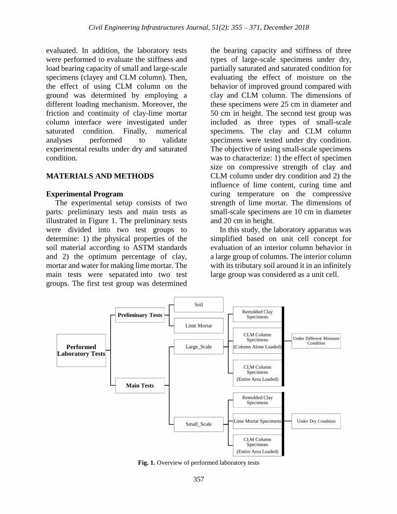
The experimental setup consists of two
parts: preliminary tests and main tests as
illustrated in Figure 1. The preliminary tests
were divided into two test groups to
determine: 1) the physical properties of the
soil material according to ASTM standards
and 2) the optimum percentage of clay,
mortar and water for making lime mortar. The
main tests were separated into two test
groups. The first test group was determined
the bearing capacity and stiffness of three
types of large-scale specimens under dry,
partially saturated and saturated condition for
evaluating the effect of moisture on the
behavior of improved ground compared with
clay and CLM column. The dimensions of
these specimens were 25 cm in diameter and
50 cm in height. The second test group was
included as three types of small-scale
specimens. The clay and CLM column
specimens were tested under dry condition.
The objective of using small-scale specimens
was to characterize: 1) the effect of specimen
size on compressive strength of clay and
CLM column under dry condition and 2) the
influence of lime content, curing time and
curing temperature on the compressive
strength of lime mortar. The dimensions of
small-scale specimens are 10 cm in diameter
and 20 cm in height.
In this study, the laboratory apparatus was
simplified based on unit cell concept for
evaluation of an interior column behavior in
a large group of columns. The interior column
with its tributary soil around it in an infinitely
large group was considered as a unit cell.
Fig. 1. Overview of performed laboratory tests
Performed Laboratory Tests
Preliminary Tests
Soil
Lime Mortar
Main Tests
Large_Scale
Remolded Clay Specimens
CLM Column Specimens
(Column Alone Loaded)
Under Different Moisture Condition
CLM Column Specimens
(Entire Area Loaded)
Small_Scale
Remolded Clay Specimens
Lime Mortar Specimens Under Dry Condition
CLM Column Specimens
(Entire Area Loaded)
Page 4
Toufigh, V. et al.
358
In this concept, a uniform loading applied
on top of the columns simultaneously and the
behavior of soil around a column was
depending on column spacing (Indraratna et
al., 2012; Ng and Tan, 2015). Since the lateral
deformations of soil across the boundaries of
the unit cell were assumed to approach zero
(Barksdale and Bachus, 1983), the boundary
of the unit cell can be simulated in the
laboratory by using a rigid exterior wall
around the column. The columns were
assumed in a triangular pattern and the
diameter of the equivalent unit cell (using
circular tributary area instead of hexagon
tributary area) was obtained from Eq. (1).
CD =1.05S (1)
where S: is the spacing between columns and
Dc: is the diameter of the equivalent unit cell
(Balaam and Booker, 1981). The space
between columns was 250 cm in the field and
25 cm (scale 1:10) in the laboratory. The area
ratio was derived as the stone column area
divided by the area being improved by the
column. Since the stiffness of CLM column
was higher than the typical stone column, the
area ratio was considered constant and equal
to 16%, in this study. Therefore, the diameter
of the unit cell and lime mortar was 25 cm and
10 cm, respectively.
The dry specimens were kept in the oven
for 7 days at 45 ºC and partially saturated
specimens were prepared by adding moisture
for simulation of field soil. The capillary
behavior of clay was used for saturating the
specimens. Thus, the mold was perforated in
the range of 17 cm (about one-third of pipe
length) from the bottom with a diameter of
0.4 cm. The specimens were floated in the
water container (about 20 cm) for 5 days as
shown in Figures 2 and 3. The partially
saturated and saturated specimens were kept
in plastic to prevent moisture loss for testing.
Fig. 2. Perforated polyethylene pipe
Fig. 3. Capillary process for saturating the specimens
Page 5
Civil Engineering Infrastructures Journal, 51(2): 355 – 371, December 2018
359
Materials Properties
Soil
In this study, the lean clay was collected
from Kerman city in Kerman province, Iran.
The physical properties of lean clay are given
in Table 1. The specific gravity of the soil
(Gs), liquid limit (LL), plastic limit (PL),
moisture content (ω) and dry unit weight of
the soil (γd) were determined based on ASTM
C127-15, ASTM D4318-17, ASTM D2216-
10 and ASTM D7263-09.
Lime Mortar
The optimum percentage of clay, mortar
and water for making lime mortar was 22%
of the weight of well-graded soil, 20% of total
weight of soil and 35% of the weight of soil
and lime together, respectively. The grain
size distribution of well-graded soil is shown
in Figure 4. As can be seen, the soil chosen is
classified as well graded sand (SW),
according to the unified soil classification
system (ASTM D422-63). Since the existing
soil had 5% of clay, 17% clay was added to
the well-graded sand. The hydrated lime
which was passed through the sieve (#40) has
been used in this study.
Specimen Preparation
Lime Specimens
The inner surface of mold wall was
covered with a thin coat of grease for ease of
removal of lime mortar from the mold
after curing for 3 days. The lime mortar was
poured into the mold and kept in laboratory
For estimating the optimum curing time,
more than 15 specimens were prepared and
cured for 28, 48, 60, 78 and 120 days at 15 ºC.
To study the effect of curing temperature on
the compressive strength of lime mortar, three
specimens were made and cured in an oven
for 7 days at 45 ºC. In addition, 15 specimens
were fabricated for different percentages of
hydrated lime content (5%, 10%, 15% and
20%) to study the effect of lime content on
compressive strength of lime mortar.
Clay Specimens
For separating the hunks of fine and
coarse particles, the clay was passed through
a 0.85 mm sieve (#20). The clay was
compacted to reach a density of 1747.2 kg/m3
in ten-layer of 5 cm thick with 16.5% water
content to simulate the field soil. The clay
water content was determined and calculated
for moisture adding amounts on each layer.
More than 9 large-scale and 9 small-scale
specimens were prepared and compacted in
the laboratory using standard Proctor method
according to ASTM D698-12.
CLM Column Specimens
Similar to clay specimens, CLM column
specimens were prepared in two different
sizes. Here, eighteen large-scale CLM
column specimens were made using the lime
mortar with the diameter of 10 cm and height
of 40 cm at the center of clay. The height of
stone column was selected with regard to
"float" columns. The punching failure
occurred at floating pile tip in soft soils. The
critical radial distance from the circumstance
of the pile in order to avoid a punching failure
was about 1.5 times of pile diameter
(Meyerhof and Sastry, 1978). Since the
stiffness of pile is higher than the stone
column, the critical distance was assumed to
be approximately equal to stone column
diameter. In this study, the thickness of the
soil beneath the CLM column was chosen to
be 10 cm for the large-scale specimens and 4
cm for the small-scale specimens. Here, ten-
layer of 5 cm thick clay was compacted with
natural moisture content and field density.
For replacing the soil with lime mortar
column, a hole was placed in the central part
with a pipe as illustrated in Figure 5a and 5b.
Then, the pipe was removed at the end of the
soil compaction and the lime mortar was
placed (Figure 5c). In addition, four small-
scale CLM column specimens were prepared
by using the lime mortar with the diameter of
4 cm and height of 16 cm at the center of clay
Page 6
Toufigh, V. et al.
360
under dry condition.
Test Procedure
The Universal Testing Machine (UTM)
and unconfined compression tests were
employed for large and small-scale
specimens, respectively. For small-scale
specimens, the failure load was applied to the
total area section of the specimen. Two
mechanisms were conducted for loading the
large-scale CLM column specimens after
making and curing processes. The first
mechanism was based on applying vertical
load only on CLM column using a rigid steel
piston with a diameter of 10 cm and height of
5 cm (Figure 6a). Settlements and loads were
monitored at regular displacement intervals
up to failure by universal test machine.
Table 1. Soil properties
Gs LL PL ω (%) 𝜸𝒅 (𝒌𝑵
𝒎𝟑)
Lean Clay 2.72 30.60 22.59 16.5 17.14
Note: Gs, specific gravity; LL, liquid limit; PL, plastic limit; ω(%), moisture content; γd, dry unit weight.
Fig. 4. Grain size distribution of well-graded sand
(a) Compacted soil layer and
pipe on the second layer
(b) Removing pipe after
completing the soil compaction
(c) Placing lime mortar in the
central part of the mold
Fig. 5. Preparing CLM column specimens
0
10
20
30
40
50
60
70
80
90
100
0.1110100
Per
cen
t fi
ner
by
wei
gh
t
Grain size (mm)
Page 7
Civil Engineering Infrastructures Journal, 51(2): 355 – 371, December 2018
361
The specimens were loaded under
displacement control (cross-head speed, 0.5
mm/min) for measuring the load‐
displacement behavior of CLM columns. For
the second mechanism, a 3 cm thick sand pad
placed on top of the specimens and the load
was applied through a 1.5 cm thick steel plate
with a diameter of 24 cm (Figure 6b). The
well-graded sand with aggregates varying
from 4.7 to 0.075 mm particles size and
relative density of 70% was used to form the
sand pad. This mechanism was conducted to
observe the load-deformation behavior of the
improved ground. Note, nine of the total
large-scale CLM column specimens were
tested using the second mechanism.
RESULTS AND DISCUSSION
Lime Specimens
Unconfined compressive strength values
of the lime mortar specimens versus the
curing time are shown in Figure 7a. The
strength of lime mortar increased rapidly at
curing for 30 to 78 days and after curing for
78 days, the rate of increase in compressive
strength reduced. This phenomenon caused
by chemical reactions between clay and lime
mortar with respect to the pozzolanic
reaction, flocculation agglomeration and lime
carbonation. Also, the activation energy was
reduced by decreasing the hydration process.
Therefore, 90 days compressive strength of
the lime mortar was approximately equal to
its ultimate strength.
As illustrated in Figure 7b, for 22% clay,
the strength ratio of lime was increased by
adding lime content; however, using lime
content more than 20% was not economical.
The influence of temperature on curing time
was also investigated in this study. The
strength of lime mortar increased by
increasing temperature as illustrated in figure
8.This could arise because the acceleration of
lime soil reactions and pozzolanic activity
increased due to the higher curing
temperature. The compressive strength of
lime mortar which is kept in an oven at 45 ºC
for 7 days was approximately equal to the
compressive strength after 28 days at 15 ºC.
According to this figure, the 28 days strength
of lime mortar was almost equal to half of the
ultimate lime mortar strength.
(a) CLM column Specimen (Column alone loaded) (b) CLM column specimen (Entire area loaded)
Fig. 6. Test arrangement of large-scale CLM column specimens
Page 8
Toufigh, V. et al.
362
a) Relationship between compressive strength of lime
mortar and curing time
b) Relationship between compressive strength of lime
mortar and lime content
Fig. 7. Effect of curing time and lime content on compressive strength of lime mortar
Fig. 8. Influence of temperature on curing time
Clay Specimens
The uniaxial compression strength of four
small clayey specimens was approximately
800 kN/m2. The typical load-deformation
behavior of large-scale clay specimen under
different conditions is presented in Figure 9.
According to the results, the bearing capacity
of clay specimen decreased significantly
under saturated condition. For investigating
the effect of moisture content on bearing
capacity, a specimen was selected randomly
from each group and the water content was
determined. The moisture content has been
played an important role in increasing the
strength of soil according to Figure 10. As can
be seen, the soil strength is decreased
approximately 80% under saturated
condition.
CLM Column Specimens (Column Alone
Loaded) The typical load-deformation behavior of
large-scale CLM column specimen under
different conditions is illustrated in Figure 11.
The axial stress of CLM column decreased
substantially under saturated condition. For
0
200
400
600
800
1000
1200
1400
0 20 40 60 80 100 120 140
σav
g(k
N/m
2)
Curing Time (day)
0
100
200
300
400
500
600
700
0 5 10 15 20 25
σav
g(k
N/m
2)
Lime (%)
0
200
400
600
800
1000
1200
At 45ºCfor 7days
28 days 48 days 60 days 78days 120days
σav
g(k
N/m
2 )
Curing time (day)
Page 9
Civil Engineering Infrastructures Journal, 51(2): 355 – 371, December 2018
363
investigating the influence of moisture
content on bearing capacity of CLM column
specimens, a specimen was selected
randomly from each group and the water
content of lime mortar was measured. Figure
12 shows the relationship between the load
bearing capacity of CLM column and water
content of lime mortar.
CLM Column Specimens (Entire Area
Loaded) The uniaxial compressive strength of four
small-scale CLM column specimens was
approximately 1100 kN/m2. As illustrated in
Figure 13, the bearing capacity of CLM
column specimens are decreased by
increasing the moisture content. It appears
that increasing in moisture content decreases
the shear strength of clay.
(a) Saturated condition (b) Dried condition
(c) Partially saturated condition
Fig. 9. Load-settlement behavior of untreated layered soils
0
5
10
15
20
25
30
0 1 2 3
Sett
lem
ent
(mm
)
Loading (kN)
Specimen 1
Specimen 2
Specimen 3
0
5
10
15
20
25
30
0 20 40 60
Sett
lem
ent
(mm
)
Loading (kN)
0
5
10
15
20
25
30
0 10 20 30 40
Sett
lem
ent
(mm
)
Loading (kN)
Page 10
Toufigh, V. et al.
364
Fig. 10. The effect of percentage of moisture on clayey specimen’s strength
(a) Saturated condition (b) Dried condition
(c) Partially saturated condition
Fig. 11. Load-settlement behavior of CLM column (column alone loaded) specimens
0
5
10
15
20
25
30
35
0 10 20 30 40 50
Load
ing
(kN
)
Water content (%)
0
5
10
15
20
25
30
0 2 4 6
Sett
lem
ent
(mm
)
Loading (kN)
0
5
10
15
20
25
30
0 10 20 30 40Se
ttle
men
t (m
m)
Loading (kN)
Specimen1
Specimen2
Specimen3
0
5
10
15
20
25
30
0 10 20 30
Sett
lem
ent
(mm
)
Loading (kN)
Page 11
Civil Engineering Infrastructures Journal, 51(2): 355 – 371, December 2018
365
Fig. 12. The effect of percentage of lime mortar moisture on strength of CLM column specimens
(a) Saturated condition (b) Dried condition
(c) Partially saturated condition
Fig. 13. Load-settlement behavior of CLM column specimen (entire area loaded)
0
5
10
15
20
25
30
0 10 20 30 40Lo
adin
g (k
N)
Water content (%)
0
2
4
6
8
10
12
0 2 4 6 8
Sett
lem
ent
(mm
)
Loading (kN)
0
2
4
6
8
10
12
0 10 20 30 40 50
Sett
lem
ent
(mm
)
Loading (kN)
0
2
4
6
8
10
12
0 10 20 30 40
Sett
lem
ent
(mm
)
Loading (kN)
Page 12
Toufigh, V. et al.
366
Friction and Continuity of Clay-Lime
Mortar Column Interface
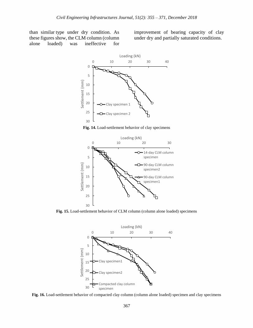
In this section, a group of large-scale
specimens was tested to indicate the friction
and continuity of clay-column interface. This
group consisted of one clay specimen, a 14-
day CLM column (column alone loaded)
specimen, two of 90-day CLM column
(column alone loaded) specimens and a
compacted clay column. The compacted clay
column specimen was performed by
replacing compacted clay as compacted lime
mortar. These specimens were made under
partially saturated condition. Figures 14 and
15 show the load-settlement curves for clay
specimens and CLM columns, respectively.
The behavior of clay specimens and
compacted clay column specimen were
illustrated in Figure 16.
As illustrated in Figure 15, the load
bearing capacity of 90-days CLM column
specimen was 1.5 times higher than 14-days
CLM column specimen. According to Figure
16, the load bearing capacity of clay
specimen was approximately equal to
compacted clay column specimen for 25 mm
settlement. Since the clay behaved the same
as compacted clay column under the partially
saturated condition, the friction and
continuity of clay-column interface were
successfully acceptable.
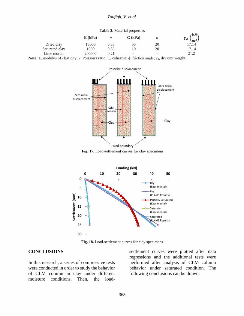
NUMERICAL MODELING
Three types of large-scale specimens in
homogeneous clay were performed for
numerical modeling. The details of the
geometry and material properties are given in
Figure 6 and Table 2, respectively. Two-
dimensional axisymmetric finite element
analysis was implemented by PLAXIS
program (Brinkgreve and Vermeer, 2010)
using elastic-perfectly plastic Mohr-Coulomb
failure criterion for the soft clay and isotropic
linear elastic behavior for lime mortar column
(Figure 17). Drained materials were used to
simulate the behavior of clay specimens and
compacted clay column specimens under
saturated and dry conditions. The load-
settlement curve obtained based on numerical
modeling is compared with
experimental load-settlement curves in
Figures 18 and 19. The results
show reasonable agreement between the
model test and numerical analysis.
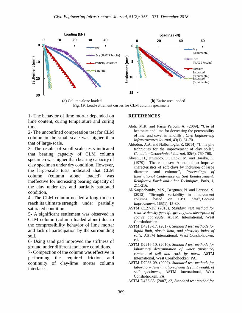
The regression was conducted on data to
gain a significantly better comprehension of
behavior of large-scale specimens
(R2 values of the regressions never fall below
0.8). Figures 18 and 19 show the behavior of
large-scale specimens under different
moisture conditions. According to these
Figures, the increasing moisture had
negative effects on load-bearing capacity of
specimens. As expected, the load-bearing
capacity of CLM column (column alone
loaded) specimens was higher than clay
specimens under saturated condition.
However, a decrease in soil moisture caused
a well-behaved increase in clay specimens.
As previously mentioned, the shear strength
of clay increased with decreasing moisture
content. The bearing capacity of clay
specimens was higher than CLM column
(column alone loaded) under partially
saturated condition (Figures 18 and 19a).
This phenomenon caused by decreasing skin
friction of CLM column under partially
saturated condition. The stiffness of
improved ground (by using a sand pad) was
performed approximately 7 times and 4 times
higher bearing capacity compared with clay
and CLM column (column alone loaded)
specimens under the saturated condition,
respectively as shown in Figure 19b. The
comparison of the results from the Figures 18
and 19 indicated that, under dry and partially
saturated conditions, the stiffness of
improved ground was approximately 2.5
times higher than clay specimen. In addition,
the behavior of partially saturated CLM
column (entire area loaded) was slightly less
Page 13
Civil Engineering Infrastructures Journal, 51(2): 355 – 371, December 2018
367
than similar type under dry condition. As
these figures show, the CLM column (column
alone loaded) was ineffective for
improvement of bearing capacity of clay
under dry and partially saturated conditions.
Fig. 14. Load-settlement behavior of clay specimens
Fig. 15. Load-settlement behavior of CLM column (column alone loaded) specimens
Fig. 16. Load-settlement behavior of compacted clay column (column alone loaded) specimen and clay specimens
0
5
10
15
20
25
30
0 10 20 30 40
Sett
lem
ent
(mm
)
Loading (kN)
Clay specimen 1
Clay specimen 2
0
5
10
15
20
25
30
0 10 20 30
Sett
lem
ent
(mm
)
Loading (kN)
14-day CLM columnspecimen
90-day CLM columnspecimen2
90-day CLM columnspecimen1
0
5
10
15
20
25
30
0 10 20 30 40
Sett
lem
ent
(mm
)
Loading (kN)
Clay specimen1
Clay specimen2
Compacted clay columnspecimen
Page 14
Toufigh, V. et al.
368
Table 2. Material properties
E (kPa) ν C (kPa) ϕ 𝜸𝒅 (𝒌𝑵
𝒎𝟑)
Dried clay 15000 0.33 55 20 17.14
Saturated clay 1000 0.35 10 20 17.14
Lime mortar 200000 0.21 - - 21.2
Note: E, modulus of elasticity; ν, Poisson's ratio; C, cohesive; ϕ, friction angle; γd, dry unit weight.
Fig. 17. Load-settlement curves for clay specimens
Fig. 18. Load-settlement curves for clay specimens
CONCLUSIONS
In this research, a series of compressive tests
were conducted in order to study the behavior
of CLM column in clay under different
moisture conditions. Then, the load-
settlement curves were plotted after data
regressions and the additional tests were
performed after analysis of CLM column
behavior under saturated condition. The
following conclusions can be drawn:
0
5
10
15
20
25
30
0 10 20 30 40 50
Sett
lem
en
t (m
m)
Loading (kN)
Dry(Exprimental)
Dry(PLAXIS Results)
Partially Saturated(Exprimental)
Saturate(Exprimental)
Saturated(PLAXIS Results)
Page 15
Civil Engineering Infrastructures Journal, 51(2): 355 – 371, December 2018
369
(a) Column alone loaded (b) Entire area loaded
Fig. 19. Load-settlement curves for CLM column specimens
1- The behavior of lime mortar depended on
lime content, curing temperature and curing
time.
2- The unconfined compression test for CLM
column in the small-scale was higher than
that of large-scale.
3- The results of small-scale tests indicated
that bearing capacity of CLM column
specimen was higher than bearing capacity of
clay specimen under dry condition. However,
the large-scale tests indicated that CLM
column (column alone loaded) was
ineffective for increasing bearing capacity of
the clay under dry and partially saturated
condition.
4- The CLM column needed a long time to
reach its ultimate strength under partially
saturated condition.
5- A significant settlement was observed in
CLM column (column loaded alone) due to
the compressibility behavior of lime mortar
and lack of participation by the surrounding
soil.
6- Using sand pad improved the stiffness of
ground under different moisture conditions.
7- Compaction of the column was effective in
performing the required friction and
continuity of clay-lime mortar column
interface.
REFERENCES
Abdi, M.R. and Parsa Pajouh, A. (2009). “Use of
bentonite and lime for decreasing the permeability
of liner and cover in landfills”, Civil Engineering
Infrastructures Journal, 43(1), 61-70.
Abiodun, A.A. and Nalbantoglu, Z. (2014). “Lime pile
techniques for the improvement of clay soils”,
Canadian Geotechnical Journal, 52(6), 760-768.
Aboshi, H., Ichimoto, E., Enoki, M. and Haraka, K.
(1979). “The composer: A method to improve
characteristics of soft clays by inclusion of large
diameter sand columns”, Proceedings of
International Conference on Soil Reinforcement:
Reinforced Earth and other Techniques, Paris, 1,
211-216.
Al-Naqshabandy, M.S., Bergman, N. and Larsson, S.
(2012). “Strength variability in lime-cement
columns based on CPT data”, Ground
Improvement, 165(1), 15-30.
ASTM C127-15. (2015), Standard test method for
relative density (specific gravity) and absorption of
coarse aggregate, ASTM International, West
Conshohocken.
ASTM D4318-17. (2017), Standard test methods for
liquid limit, plastic limit, and plasticity index of
soils, ASTM International, West Conshohocken,
PA.
ASTM D2216-10. (2010), Standard test methods for
laboratory determination of water (moisture)
content of soil and rock by mass, ASTM
International, West Conshohocken, PA.
ASTM D7263-09. (2009), Standard test methods for
laboratory determination of density (unit weight) of
soil specimens, ASTM International, West
Conshohocken, PA.
ASTM D422-63. (2007) e2, Standard test method for
0
10
20
30
0 10 20 30 40
Sett
lem
en
t (m
m)
Loading (kN)
Dry
Dry (PLAXIS Results)
Partially Saturated
Saturate
0
5
10
15
0 20 40 60
Sett
lem
en
t (m
m)
Loading (kN)
Dry(Exprimental)
Dry(PLAXIS Results)
PartiallySaturated(Exprimental)Saturated(Exprimental)
Page 16
Toufigh, V. et al.
370
particle-Size analysis of soils (withdrawn 2016),
ASTM International, West Conshohocken, PA.
ASTM D698-12. (2012), Standard test methods for
laboratory compaction characteristics of soil using
standard effort (12400 ft-lbf/ft3 (600 kN-m/m3)),
ASTM International, West Conshohocken, PA.
Baumann, V. and Bauer, G.E.A. (1974). “The
performance of foundations on various soils
stabilized by the vibro-compaction
method”, Canadian Geotechnical Journal, 11(4),
509-530.
Balaam, N. and Booker, J.R. (1981). “Analysis of rigid
rafts supported by granular piles", International
Journal for Numerical and Analytical Methods in
Geomechanics, 5(4), 379-403.
Barksdale, R.D. and Bachus, R.C. (1983). Design and
construction of stone columns, Volume II,
Appendixes, Federal Highway Administration,
Washington, DC.
Brinkgreve, R.B.J. and Vermeer, P.A. (2010).
PLAXIS: Finite Element code for soil and rock
analyses, Version 8, Balkema.
Broms, B.B., Holm, G. and Bredenberg, H. (1999).
Dry mix method for deep soil
stabilization, Balkema Rotterdam.
Chai, J.-C., Miura, N. and Koga, H. (2005). “Lateral
displacement of ground caused by soil–cement
column installation”, Journal of Geotechnical and
Geoenvironmental Engineering, 131(5), 623-632.
Chong, S.Y. and Kassim, K.A. (2014). “Consolidation
characteristics of lime column and Geotextile
Encapsulated Lime Column (GELC) stabilized
pontian marine clay”, Electronic Journal of
Geotechnical Engineering, 19A, 129-141.
Dash, S.K. and Hussain, M. (2011). “Lime
stabilization of soils: Reappraisal”, Journal of
Materials in Civil Engineering, 24(6), 707-714.
Di Sante, M., Fratalocchi, E., Mazzieri, F. and
Pasqualini, E. (2014). “Time of reactions in a lime
treated clayey soil and influence of curing
conditions on its microstructure and
behaviour”, Applied Clay Science, 99, 100-109.
Farouk, A. and Shahien, M.M. (2013). “Ground
improvement using soil–cement columns:
Experimental investigation”, Alexandria
Engineering Journal, 52(4), 733-740.
Farzaneh, O. and Mosadegh, A. (2011). “Experimental
analysis to evaluate the effectiveness of lime and
non-traditional additives on subgrade soil
stabilization of Kerman-Zangiabad road”, Civil
Engineering Infrastructures Journal, 45(1), 23-33.
Geiman, C.M. (2005). “Stabilization of soft clay
subgrades in Virginia phase I laboratory study”,
PhD Thesis, Virginia Polytechnic Institute and
State University.
Harichane, K., Ghrici, M., Kenai, S. and Grine, K.
(2011). “Use of natural pozzolana and lime for
stabilization of cohesive soils”, Geotechnical and
geological engineering, 29(5), 759-769.
Horpibulsuk, S., Rachan, R. and Suddeepong, A.
(2011). “Assessment of strength development in
blended cement admixed Bangkok clay”,
Construction and Building Materials, 25(4), 1521-
1531.
Hughes, J. and Withers, N. (1974). “Reinforcing of
soft cohesive soils with stone columns”, Ground
Engineering, 7(3), 42-49.
Indraratna, B., Basack, S. and Rujikiatkamjorn, C.
(2012). “Numerical solution of stone column–
improved soft soil considering arching, clogging,
and smear effects”, Journal of Geotechnical and
Geoenvironmental Engineering, 139(3), 377-394.
Jawad, I.T., Taha, M.R., Majeed, Z.H. and Khan, T.A.
(2014). “Soil stabilization using lime: Advantages,
disadvantages and proposing a potential
alternative”, Research Journal of Applied Sciences,
Engineering and Technology, 8(4), 510-520.
Jha, A.K. and Sivapullaiah, P.V. (2016). “Volume
change behavior of lime treated gypseous soil-
influence of mineralogy and
microstructure”, Applied Clay Science, 119, 202-
212.
Kassim, K., Hamir, R. and Kok, K. (2005).
“Modification and stabilization of Malaysian
cohesive soils with lime”, Geotechnical
Engineering, 36(2), 123-132.
Larsson, S., Rothhämel, M. and Jacks, G. (2009). “A
laboratory study on strength loss in kaolin
surrounding lime–cement columns”, Applied Clay
Science, 44(1), 116-126.
Malekpoor, M.R. and Poorebrahim, G. (2015).
“Behavior of compacted lime-(well-graded) soil
columns: Large scale tests and numerical
modelling”, KSCE Journal of Civil Engineering,
19(4), 893-903.
Mallela, J., Quintus, H.V. and Smith, K. (2004).
“Consideration of lime-stabilized layers in
mechanistic-empirical pavement design”, The
National Lime Association, 200-208.
Meyerhof, G. and Sastry, V. (1978). “Bearing capacity
of piles in layered soils, Part 2: Sand overlying
clay”, Canadian Geotechnical Journal, 15(2), 183-
189.
Mitchell, J.K. and Hooper, D.R. (1961). “Influence of
time between mixing and compaction on properties
of a lime-stabilized expansive clay”, Highway
Research Board Bulletin, 304.
Mousavi, S.E. and Wong, L.S. (2016). “Permeability
characteristics of compacted and stabilized clay
with cement, peat ash and silica sand”, Civil
Engineering Infrastructures Journal, 49(1), 149-
164.
Page 17
Civil Engineering Infrastructures Journal, 51(2): 355 – 371, December 2018
371
Nalbantoglu, Z. and Gucbilmez, E. (2002).
“Utilization of an industrial waste in calcareous
expansive clay stabilization”, Geotechnical Testing
Journal, 25(1), 78-84.
Ng, K. and Tan, S. (2015). “Nonlinear behaviour of an
embankment on floating stone columns”,
Geomechanics and Geoengineering, 10(1), 30-44.
Priebe, H. (1976). “Abschätzung des
setzungsverhaltens eines durch stopfverdichtung
verbesserten baugrundes”, Die Bautechnik, 53(5),
160-162.
Romeo, L.M., Catalina, D., Lisbona, P., Lara, Y. and
Martínez, A. (2011). “Reduction of greenhouse gas
emissions by integration of cement plants, power
plants, and CO2 capture systems”, Greenhouse
Gases: Science and Technology, 1(1), 72-82.
Sukontasukkul, P. and Jamsawang, P. (2012). “Use of
steel and polypropylene fibers to improve flexural
performance of deep soil-cement column”,
Construction and Building Materials, 29(1), 201-
205.
Tang, A. M., Vu, M. N. and Cui, Y. J. (2011). “Effects
of the maximum soil aggregates size and cyclic
wetting-drying on the stiffness of a lime-treated
clayey soil”, Géotechnique, 61(5), 421-429.
Toufigh, M.M. and Malekpoor, M.R. (2010).
“Laboratory study of soft soil improvement using
lime mortar-(well graded) soil columns”, ASTM
geotechnical testing journal, 33(3), 225-235.
Wilkinson, A., Haque, A., Kodikara, J., Christie, D.
and Adamson, J. (2004). “Stabilization of reactive
subgrades by cementitious slurry injection–a
review”, Australian Geomechanics Journal, 39(4),
81-93.
Yapage, N.N.S., Liyanapathirana, D.S., Kelly, R.B.,
Poulos, H.G. and Leo, C.J. (2014). “Numerical
modeling of an embankment over soft ground
improved with deep cement mixed columns: Case
history”, Journal of Geotechnical and
Geoenvironmental Engineering, 140(11),
04014062.